

Premier 2-Zone Controller
model 140202
Installer Guide
Controlador de 2 zonas premier
modelo 140202
Guía de instalación
Régulateur 2 zones de première qualité
modèle 140202
Guide de l’installateur
English, 1-11
Español, 12-22
Français, 23-33
140202-100-002
CONTENTS
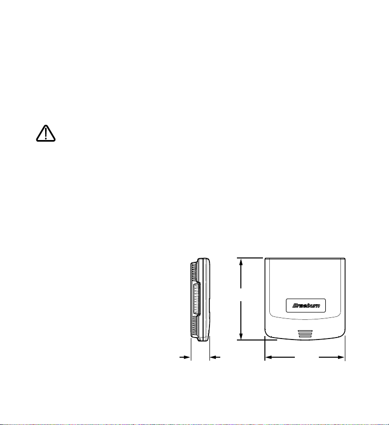
6.00”
1.25”
6.00”
1 Specifications 4 Configuration
2 Suitable Mounting Locations 5 System Checkout
3 Wiring Diagrams 6 Operation
Warning
• Read all of the instructions before proceeding.
• Always turn off power to the heating/air conditioning system prior to installing or adjusting the
Premier 2-Zone Controller. Wire the entire panel before applying transformer power.
• This controller should only be installed and configured as described in this manual. Any other use is
not recommended and will void the warranty.
Specifications
1
• Storage temperature: -40º–150ºF
(-40º–65ºC)
• Operating temperature: -20º–125ºF
(-30º–50ºC)
• Operating humidity: 5–95% RH
• Voltage: 24 VAC, 60Hz
• Max. damper power: 35 VA @ 24 VAC
• Dimensions: See Figure 1
Figure 1
1

Suitable Mounting Locations
return air
ducts
return air
plenum
bypass
duct
coil
supply air
sensor
zone dampers
electric or
barometric
bypass damper
filtration
system
furnace
typical mounting location
4.50”
2
Mount the Premier 2-Zone Controller panel near the HVAC equipment (see Figure 2). The panel can be
mounted in any orientation on a wall, stud, roof truss, or the return-air plenum. For appearance, mount the
panel level.
Remove the panel cover and use the base as a template to drill mounting holes 4.5” apart (see Figure 3).
Attach the panel with appropriate screws (not included). Use mounting anchors as needed for drywall or
plaster installations.
Figure 2
2
Figure 3

Wiring the Panel
3
Always turn off power to the heating/air conditioning system prior to installing or
adjusting the Premier 2-Zone Controller. Wire the entire panel before applying
transformer power.
Use the following general wiring instructions for all systems. Specific wiring will vary depending on the
equipment and type of system (conventional or heat pump).
3.1 Damper Wiring
Install the system dampers using the instructions provided
by the manufacturer.
Connect the dampers to the zone panel as shown for
either a 2-wire or 3-wire damper.
The sum of all dampers powered by the zone panel
should not exceed 35 VA at 24 VAC. Use a slave relay if
additional damper power is required.
PO
COM
PC
Zone Panel 2-Wire Damper
M
M
Max. damper VA per panel 35 VA @ 24 VAC
PO
COM
PC
Zone Panel 3-Wire Damper
PO
C
PC
3

3.2 Thermostat Wiring
Install the system thermostats using the instructions
provided by the manufacturer.
Connect the thermostats to the zone panel as shown.
Notes:
• Wiring to the C terminal is required only for
thermostat power.
• E terminal at thermostat 1 controls emergency heat.
See E-Heat Switch Installation Sheet TSB-0708-01
for wiring details.
Rh
Rc
Y
G
W
C
Thermostat Zone Panel
E
R
Y
G
W
C
3.3 Transformer Wiring
Install the transformer using the instructions provided
by the manufacturer. Size the transformer to the damper
requirements. The zone panel has a built-in, self-resetting
fuse. The maximum damper power per panel is 35 VA at
24 VAC.
Connect the transformer to the zone panel as shown.
Note: Additional dampers or dampers with a higher current draw will require the use of a separate
slave relay.
HOT
Dedicated
Zoning Transformer
CC
Zone
Panel
24V
24C
4

3.4 Conventional System Wiring
Note: For a heat pump system, see Section 3.5.
Connect a conventional heating system to
the zone panel as shown.
For a single stage heating and cooling
system, the 2nd stage connections are
not used.
For a system using a dual transformer,
open jumper J1 (see Configuration
RH
RC
Y
G
W1
EH
W2
O/B
C
1st stage
compressor
control
1st stage
heat
control
1st stage
fan
control
2nd stage
heat
control
24 VAC
section, Figure 4). Make sure the neutrals
(common) are connected.
3.5 Heat Pump System Wiring
Connect a single or multi-stage
heat pump system to the zone panel
as shown.
A conventional thermostat may be used
with a heat pump system, however,
emergency heat will be controlled by
the panel emergency heat switch or the
optional remote emergency heat switch.
For a single-stage system, the auxiliary
heat control is not used. For a multistage system, the compressor controls
are not used.
• Use DIP switch 1 to select between conventional and heat pump system.
• Use DIP switch 3 for heat pump reversing valve control. Setting 0 means that the O/B terminal is
active in a cooling call. Setting B means that the O/B terminal is active in a heating call.
RH
RC
Y
G
W1
EH
W2
O/B
C
1st stage
compressor
control
aux heat /
E-heat
control
1st stage
fan
control
reversing
valve
24 VAC
HOT
C
HOT
C
5

Configuration
Braeburn
2-Zone
4
Use the following instructions to configure the Premier 2-Zone Controller.
1. Open J1 jumper for dual transformer installations.
2. Open J2 short cycle protection jumper for system test.
Note: Replace J2 when system testing is completed or leave J2 open if compressor has built in
short cycle protection.
J1 jumper
JI REMOVE TO SEPARATE
J2 jumper
NON HP
NORMAL
REV VALVE B
FAN GAS
OPP CALL 20
LOCKOUT NONE
PRIORITY ALL
J2-SHORT CYCLE
PROTECTION
RH AND RC TERMINAL
FLASHING
WHEN NORMAL
HEAT PUMP
DUAL FUEL
O
ELEC/HP
15
ACTIVE
ZONE1
EMERGENCY
HEAT
ON OFF
RH
RC
Y
G
W1
EH
W2
O/B
C
EQUIPMENT
Figure 4
6

3. Set the DIP switches to meet system requirements.
NON HP
NORMAL
REV VALVE B
FAN GAS
OPP CALL 20
LOCKOUT NONE
PRIORITY ALL
HEAT PUMP
DUAL FUEL
O
ELEC/HP
15
ACTIVE
ZONE1
Switch Label Function
1 Non-HP / Heat Pump Conventional or heat pump control of W/Y
2 Normal / Dual Fuel HP 1st stage lockout on 2nd stage call
3 Rev Valve B / O O/B terminal active in heating (B position) or cooling (O position)
4 Fan Gas / Elec & HP Fan controlled by HVAC system or panel
5 Opp Call 20 / 15 Opposite call answer time in minutes
6 Lockout None / Active 2nd stage lockout without 2 zones calling
7 Priority All / Zone 1 Changeover priority zone 1 or first call
System Checkout
5
After the wiring and configuration is complete, use the following checklist to verify the panel operation
is correct.
[ ] Make sure the Emergency Heat Switch is in the Off (right) position.
[ ] Open jumper J2 by moving cap from both pins to only one pin.
[ ] Use table and diagram in section 4 of this installer guide or inside the zone panel cover to
verify DIP switches are set properly.
[ ] Make sure no zones are calling by turning off zone 1 and zone 2 thermostats.
[ ] Apply 24 VAC power to the panel.
[ ] Verify green power LED near 24 VAC terminals is lit.
7

[ ] Verify green heartbeat LED in middle of panel is pulsing.
[ ] Verify zone LEDs near damper terminals are green.
[ ] Switch zone 1 thermostat to heat mode, and call for heat in zone 1 by raising set
[ ] Verify zone 1 damper LED stays green (open) and zone 2 damper LED changes to red
[ ] Verify heating system is operating, air is moving out zone 1 vents, and zone 2 vents have
[ ] Switch zone 2 thermostat to heat mode, and call for heat in zone 2 by raising set
[ ] Verify zone 1 damper LED stays green (open) and zone 2 damper LED changes to
[ ] Verify heating system is operating and air is moving out into zone 1 and zone 2.
[ ] If installed, verify emergency heat remote and panel switch. Return E-Heat switches to
[ ] Return zone 1 thermostat to the off position. Verify zone 1 damper LED turns red and
[ ] Verify heating system is operating, air is moving out zone 2 vents, and zone 1 vents have
[ ] Return zone 2 thermostat to the off position. Verify system fan shuts off at the end of
[ ] Verify zone LEDs near damper terminals are green.
[ ] If the outside temperature is acceptable, repeat the above steps in cooling mode.
[ ] Restore thermostats and replace J2 jumper if short cycle protection at zone panel
temperature above room temperature.
(closed).
minimal airflow.
temperature above room temperature.
green (open).
normal position when test is complete.
zone 2 damper LED stays green.
minimal airflow.
90-second purge cycle.
Cooling will not work if E-Heat is on.
is required.
8

Operation
6
The Premier 2-Zone Panel has LEDs to tell the installer and homeowner the current operating mode of the
panel. Refer to Figure 5 and the following descriptions of the panel LEDs for operation information.
Callout LED Description
1 Heartbeat Flashes once per second when the panel is normal.
2 RH and RC Lights when the HVAC equipment transformer(s) are receiving power.
3 24V Power Lights when the panel is receiving power from the zoning transformer.
4 Damper Lights red when the zone damper is closed, green when the zone
Notes:
• When no zones are calling, the panel will command all dampers to open.
• For maximum energy conservation, a 90 second purge will occur at the end of each call. No calls will
be answered until the purge is complete.
• Equipment staging is automatic based on time.
• No cooling calls will be answered if emergency heat is switched on.
Available only when C equipment terminal is wired.
damper is open.
9

Braeburn
2-Zone
1
JI REMOVE TO SEPARATE
RH AND RC TERMINAL
2
RH
FLASHING
THERMOSTAT1
R
Y
G
W
E
NON HP
NORMAL
REV VALVE B
FAN GAS
OPP CALL 20
LOCKOUT NONE
PRIORITY ALL
WHEN NORMAL
HEAT PUMP
DUAL FUEL
O
ELEC/HP
15
ACTIVE
ZONE1
RC
Y
G
W1
EH
W2
O/B
C
EQUIPMENT
C
THERMOSTAT2
PWR
R
Y
G
W
C
24V
24C
J2-SHORT CYCLE
PROTECTION
EMERGENCY
HEAT
ON OFF
Z1-PO
COM
Z1-PC
Z2-PO
COM
DAMPER 1
DAMPER 2
4
Z2-PC
3
Figure 5
10

Warranty
Braeburn Systems LLC warrants each new Braeburn zone panel against any defects that are due to faulty
material or workmanship for a period of five years after the original date of purchase by a professional
service technician. This warranty and our liability does not apply to merchandise or the zone panel resulting
from accident, alteration, neglect, misuse, improper installation or any other failure to
follow Braeburn installation and operating instructions.
Braeburn Systems LLC agrees to repair or replace at its option any Braeburn zone panel under warranty
provided it is returned postage prepaid to our warranty facility in a padded carton within the warranty period,
with proof of the original date of purchase and a brief description of the malfunction. This limited warranty
does not include the cost of removal or re-installation.
This warranty gives you specific legal rights and you may also have other rights that vary from state to state
or province to province. Answers to any questions regarding our limited warranty may be obtained by writing
our corporate offices.
WARRANTY FACILITY: Braeburn Systems LLC
Attn: Warranty Department
2215 Cornell Avenue
Montgomery, IL 60538
Braeburn Systems LLC
2215CornellAvenue•Montgomery,IL60538
Technical Assistance: www.braeburnonline.com
Call us toll-free: 866.268.5599 (U.S.) or +1.630.844.1968 (Outside the U.S.)
5
YEAR
LIMITED
WARRANTY
©2010BraeburnSystemsLLC•AllRightsReserved.
MadeinChina•140202-100-002
11
 Loading...