

Page 1

Page 2

Table Of Contents
Preface............................................................................................................................................. 1
Welcome to the NetDoc™ Online User Guide........................................................................... 1
Usage Notes............................................................................................................................1
Printable Information.............................................................................................................. 1
Web Site.................................................................................................................................. 1
Online User Guide Overview...................................................................................................... 1
NetDoc Documentation .............................................................................................................. 2
Copyright and Trademarks ......................................................................................................... 2
Technical Support Contact Information...................................................................................... 3
United States and Canada ....................................................................................................... 3
Getting Started................................................................................................................................4
Getting Started in NetDoc........................................................................................................... 4
NetDoc Overview ....................................................................................................................... 4
System Requirements.................................................................................................................. 5
Client Workstation Requirements........................................................................................... 5
Server Requirements............................................................................................................... 5
Installing NetDoc............................................................................................................................ 6
Preparing to Install NetDoc ........................................................................................................ 6
Before You Begin...................................................................................................................6
Installation Overview.............................................................................................................. 6
Installing NetDoc on Your IIS Server ........................................................................................ 7
Creating the SQL Server Database.............................................................................................9
Configuring SQL Server Security (optional)............................................................................ 13
Configuring IIS to Display NetDoc on an Intranet................................................................... 16
To configure IIS for Windows Server 2000 ......................................................................... 16
To configure IIS for Windows Server 2003 ......................................................................... 20
Connecting NetDoc IIS to NetDoc SQL Server.......................................................................22
Adding NetDoc users................................................................................................................ 22
Configuring Security for NetDoc Login (optional)..................................................................23
To access the settings:........................................................................................................... 24
Upgrading from an Earlier Version of NetDoc............................................................................. 26
To upgrade to NetDoc v1.1:.................................................................................................. 26
Exploring NetDoc......................................................................................................................... 27
Exploring the NetDoc Environment ......................................................................................... 27
The NetDoc Main Page............................................................................................................. 27
Links from the NetDoc Main Page....................................................................................... 27
NetDoc Main Menu .................................................................................................................. 28
The NetDoc Environment............................................................................................................. 30
Navigator Tree..........................................................................................................................30
Hierarchy Descriptions ............................................................................................................. 30
Location Info............................................................................................................................. 31
List View................................................................................................................................... 31
Detail View............................................................................................................................... 33
Attachments .............................................................................................................................. 34
ii
Page 3

Table Of Contents
To add an Attachment:.......................................................................................................... 34
To view an Attachment:........................................................................................................ 34
To delete an Attachment:...................................................................................................... 34
Notes.........................................................................................................................................35
To add Notes:........................................................................................................................ 35
To add additional Notes to the Port or Strand Level: ........................................................... 35
To delete Notes:.................................................................................................................... 36
Revision Log............................................................................................................................. 36
NetDoc Tools Available Within the Application.......................................................................... 37
Multi-View Multi-Task Capability........................................................................................... 37
Window Sizing.......................................................................................................................... 37
Search Function ........................................................................................................................ 37
To use the search function:...................................................................................................37
Quick Set/Quick Insert Buttons................................................................................................38
View Most Recently Added Items............................................................................................ 38
Copy Capabilities...................................................................................................................... 39
Copy Button.............................................................................................................................. 39
To use the Copy function:.....................................................................................................39
To Excel Button........................................................................................................................ 39
To copy to Excel:.................................................................................................................. 39
To Clipboard Button.................................................................................................................40
To copy to the clipboard:...................................................................................................... 40
Circuit Trace Tool..................................................................................................................... 40
About the Circuit Trace Tool................................................................................................ 40
Accessing the Circuit Trace Tool ......................................................................................... 40
Viewing Circuit Information................................................................................................. 41
Show/Hide Table or Diagram............................................................................................... 41
Invert Table........................................................................................................................... 41
Copy to Clipboard................................................................................................................. 41
Print....................................................................................................................................... 41
Arranging the Diagram......................................................................................................... 42
Viewing a Component’s Detail............................................................................................. 42
Changing the Trace Point...................................................................................................... 42
NetDoc Tools Accessed from the NetDoc Main Page.................................................................. 43
Exporting to LabelMark™........................................................................................................ 43
To export to LabelMark........................................................................................................ 43
Tester Data Features ................................................................................................................. 44
About the Tester Data Import Tool....................................................................................... 44
Importing Tester Data........................................................................................................... 45
Viewing Test Data ................................................................................................................ 46
Matching Tester Data............................................................................................................ 46
Deleting Imported Tester Data Sets...................................................................................... 47
User Defined Fields .................................................................................................................. 47
Custom Fields ........................................................................................................................... 47
To create customized fields:................................................................................................. 48
Security Log.............................................................................................................................. 48
iii
Page 4

NetDoc User Guide
To view the Security Log:..................................................................................................... 49
Enable/Disable Features............................................................................................................ 49
NetDoc Wizards............................................................................................................................ 51
About NetDoc's Wizards .......................................................................................................... 51
Infrastructure Setup Wizards .................................................................................................... 51
To use an infrastructure setup wizard:.................................................................................. 52
Documentation Wizards............................................................................................................ 53
Port Naming Wizard............................................................................................................. 53
Setting Up the Geographical Infrastructure.................................................................................. 55
About the Infrastructure............................................................................................................ 55
Setting Up Companies .............................................................................................................. 55
To set up a Company:........................................................................................................... 55
Setting Up Infrastructure Within a Company............................................................................... 57
Campuses.................................................................................................................................. 57
To add a Campus: ................................................................................................................. 57
To remove a Campus:........................................................................................................... 57
Buildings................................................................................................................................... 58
To add a Building: ................................................................................................................ 58
To remove a Building:.......................................................................................................... 58
Floors ........................................................................................................................................ 58
To add a Floor:...................................................................................................................... 59
To remove a Floor:................................................................................................................ 59
Indoor Spaces............................................................................................................................ 59
To add an Indoor Space:....................................................................................................... 59
Telecommunication Spaces ...................................................................................................... 60
To add a Telecommunication Space:.................................................................................... 60
Outdoor Spaces......................................................................................................................... 61
To add an Outdoor Space:..................................................................................................... 61
To remove an Outdoor Space: .............................................................................................. 62
Faceplates.................................................................................................................................. 62
To add a Faceplate:............................................................................................................... 62
To remove a Faceplate:......................................................................................................... 62
Ports .......................................................................................................................................... 63
To add a Port:........................................................................................................................ 63
To remove a Port:.................................................................................................................. 63
Setting Up the Cabling Infrastructure........................................................................................... 64
About the Cabling Infrastructure.............................................................................................. 64
Termination Hardware.............................................................................................................. 64
About Termination Hardware............................................................................................... 64
Adding Termination Hardware............................................................................................. 64
Defining Termination Hardware........................................................................................... 65
Start and End Port/Position................................................................................................... 65
Editing Port/Position Status.................................................................................................. 65
Connecting Termination Hardware to a Backbone Cable.................................................... 66
Connecting to a Horizontal Link........................................................................................... 66
Connecting to a Grounding Conductor................................................................................. 66
iv
Page 5

Table Of Contents
Assets........................................................................................................................................ 66
About Assets......................................................................................................................... 66
Setting Up Asset Types......................................................................................................... 66
Backbone Assets................................................................................................................... 67
Workstation Assets............................................................................................................... 67
Financials.............................................................................................................................. 67
Horizontal Links ....................................................................................................................... 68
About Horizontal Links ........................................................................................................ 68
Horizontal Link (HL) Info.................................................................................................... 68
Defining Horizontal Links.................................................................................................... 69
Connecting Contacts to a Horizontal Link............................................................................ 69
Connecting Workstation Assets to a Horizontal Link .......................................................... 69
Connecting a Data Horizontal Link to a Backbone Asset .................................................... 69
Connecting a Data Horizontal Link to a Mainframe Asset................................................... 70
Connecting a Voice Horizontal Link to a Backbone Asset .................................................. 70
Connecting a Horizontal Link to Termination Hardware..................................................... 70
Identifying Horizontal Link Pathways Used......................................................................... 71
Editing the Key Sheet ........................................................................................................... 71
Connecting a Horizontal Link to a Grounding Conductor.................................................... 71
Splices....................................................................................................................................... 71
Adding Splices...................................................................................................................... 71
Splice Types (User Defined)................................................................................................. 72
Connecting a Backbone Cable to a Splice............................................................................ 72
Backbones................................................................................................................................. 72
Backbone Cables................................................................................................................... 72
Adding a Backbone............................................................................................................... 72
Defining a Backbone............................................................................................................. 73
Backbone Source .................................................................................................................. 73
Backbone Source .................................................................................................................. 74
Backbone Destination........................................................................................................... 74
Backbone Pair/Strand Details............................................................................................... 74
Backbone Cross-Connects.................................................................................................... 75
Identifying Backbone Pathways Used.................................................................................. 75
Connecting a Backbone to a Grounding Conductor............................................................. 75
Grounding................................................................................................................................. 76
About Grounding.................................................................................................................. 76
Adding Busbars..................................................................................................................... 76
Adding a Conductor.............................................................................................................. 76
Conductor Pathways Used.................................................................................................... 77
Firestops.................................................................................................................................... 78
Firestop Information ............................................................................................................. 78
Adding a Firestop.................................................................................................................. 78
Connecting a Firestop to a Pathway...................................................................................... 78
Pathways................................................................................................................................... 78
About Pathways.................................................................................................................... 78
Adding a Pathway................................................................................................................. 79
v
Page 6

NetDoc User Guide
Cables in Pathways............................................................................................................... 79
Connecting a Pathway to a Firestop...................................................................................... 79
Connecting the Pathways...................................................................................................... 79
Contacts..................................................................................................................................... 80
Adding a Contact .................................................................................................................. 80
Defining a Contact................................................................................................................ 80
Adding Departments............................................................................................................. 81
Connecting a User to Horizontal Links ................................................................................ 81
Creating NetDoc Specific Users........................................................................................... 81
Reports.......................................................................................................................................... 82
About the Report Creator.......................................................................................................... 82
How to Run a Report ................................................................................................................ 82
To generate a report from the Report Creator:...................................................................... 82
Sorting, Filtering, and Grouping Reports ................................................................................. 82
Selecting Data for a Report................................................................................................... 82
Grouping Data on a Report................................................................................................... 83
Sorting a Report.................................................................................................................... 83
Report Detail......................................................................................................................... 83
Header Color......................................................................................................................... 83
The Print Details Button........................................................................................................... 83
Available Reports...................................................................................................................... 83
An additional report is available from NetDoc’s List View:................................................ 84
Spreadsheet Tool........................................................................................................................... 85
Spreadsheet Tool (Import from Excel)..................................................................................... 85
About the Spreadsheet Tool...................................................................................................... 85
Launching the Spreadsheet Tool............................................................................................... 85
To launch NetDoc’s Spreadsheet Tool:................................................................................ 85
Using the Import Tool to Transfer Data to NetDoc.................................................................. 86
To add data to the Import Tool:............................................................................................ 86
To Check Data:..................................................................................................................... 86
To Import Data:..................................................................................................................... 87
Appendix....................................................................................................................................... 88
Product Functionality................................................................................................................ 88
vi
Page 7
Preface
Welcome to the NetDoc™ Online User Guide
Usage Notes
As you use the NetDoc Online User Guide:
• When you see text like this - sample - click it to jump to related information. Click Back
on your browser to return to your starting point.
• Click Contents, Index or Search at the top of the screen to find the information you're
looking for. See
Printable Information
• NetDoc User Guide
Web Site
Online User Guide Overview for details on using these features.
Click the link below to display your local Brady web site.
• Brady Web Site
Online User Guide Overview
Select Help Æ User Guide to display the NetDoc electronic reference system. It appears in a
standard web browser window, but has the following additional features:
• Contents – Displays a list of categories and topics in the order you would naturally read
them. Click on the category to list its individual topics. Click a topic to display it.
• Index – Displays an organized list of related topics. Browse the list or type a keyword
and press Enter to jump to it.
• Search – Allows you to find words and phrases within the full text of the guide.
• Jump – Allows you to jump to a relevant topic or website by clicking blue underlined
text. Click
• Browse – Allows you to read topics in a logical order. Click the buttons (Previous
Topic and Next Topic) to browse through the guide.
(the Back button on your browser) to return to your starting point.
• Browser buttons – You can also use the forward and back buttons on your web browser
to retrace the steps you have taken from topic to topic.
• Hide Navigation – Click the button to hide the Contents, Index or Search navigation
information so you can display more of the user guide text. Click Contents, Index or
Search tab at the top of the screen to re-display the navigation information.
1
Page 8

NetDoc User Guide
NetDoc Documentation
Brady provides four sources of documentation for your reference when using NetDoc:
• Online User Guide – A full-featured electronic reference system installed with the
application (select Help Æ User Guide).
• User Guide .PDF File – A printable version of the online user guide is installed with the
application. (To open it, click
• Printed Quick Start Guide
here.)
Copyright and Trademarks
This manual is proprietary to Brady Worldwide, Inc. (hereafter "Brady"), and may be revised
from time to time without notice. Brady disclaims any understanding to provide you with such
revisions, if any.
This manual is copyrighted with all rights reserved. No portion of this manual may be copied or
reproduced by any means without the prior written consent of Brady.
While every precaution has been taken in the preparation of this document, Brady assumes no
liability to any party for any loss or damage caused by errors or omissions or by statements
resulting from negligence, accident, or any other cause. Brady further assumes no liability arising
out of the application or use of any product or system described, herein; nor any liability for
incidental or consequential damages arising from the use of this document. Brady disclaims all
warranties of merchantability of fitness for a particular purpose.
Brady reserves the right to make changes without further notice to any product or system
described herein to improve reliability, function, or design.
Microsoft, Windows, Excel, Word, Access and SQL Server are registered trademarks of
Microsoft Corporation.
NetDoc™ (hereafter "NetDoc") is a trademark of Brady Worldwide, Inc.
LabelMark™ is a trademark of Brady Worldwide, Inc.
All brand or product names referenced in this manual are trademarks (™) or registered
trademarks (®) of their respective companies or organizations.
© 2005 Brady Worldwide, Inc. All Rights Reserved
2
Page 9

Technical Support Contact Information
United States and Canada
Preface
Phone:
FAX:
Email:
1-800-643-8766
(M-F 6:30 a.m. - 6:30 p.m. Central
Time
1-800-358-6767
tech_support@bradycorp.com
3
Page 10

Getting St arted
Getting Started in NetDoc
To begin using NetDoc, you can get a general understanding of its functions and features by
reading the
performance of the application. Then, follow the detailed instructions for proper installation, and
Explore the NetDoc Environment. From there, you can set up the system to best meet your
cabling and infrastructure needs.
NetDoc Overview
NetDoc is a web enabled database package that will enable you to better document and manage
your complete network. With this Cable Management Solution (CMS), you can document
horizontal and backbone cables, hardware, assets, pathways, locations, users, and much more.
Beyond everything that NetDoc is able to do; information can also be seamlessly exported into
LabelMark software to assist you in easily labeling your entire infrastructure. Brady’s
documentation solutions, labeling solutions, and an assortment of printers will increase
productivity, reduce costs, and improve user services in a very user-friendly environment.
NetDoc Overview. Also, ensure you meet the System Requirements for optimal
The NetDoc interface runs on Microsoft SQL Server (MSS). MSS is designed to support one or
several users. Each database created will keep track of data associated with your infrastructure.
When a change is made to your infrastructure, such as adding a new component, updating or
removing components, you can make the change directly in NetDoc in several different methods.
In addition, the ANSI/TIA/EIA 606A has changed standards for guidelines and classes of
administration for telecommunications infrastructure. NetDoc was built according to the new
standards, simplifying your firm’s transition to them. As an open, user-friendly CMS package,
each organization can document and label according to the methods chosen to be followed.
4
Page 11
System Requirements
Client Workstation Requirements
Hardware Software
Getting Started
Minimum Requirements:
• 750 MHz Processor
• 256 MB Ram
• SVGA w/24-bit color
• 1024x768 minimum screen
resolution
• Mouse
• Windows compatible printer
Requirements:
• Windows 2000, Windows XP Home,
• Internet Explorer 6.0
Server Requirements
Hardware Software
Minimum Requirements:
• 750 MHz Processor
• 512 MB Ram
• 30 GB disk drive
Requirements:
• Windows 2000 Server or Windows
• IIS 5.0 – 6.0
• .Net Framework 1.1
Recommended:
• 2 GHz Processor
• SQL Server 2000 Standard or
or Windows XP Professional
2003 Server
Enterprise edition
• 1 GB Ram
• 30+ GB disk drive
• 17” SVGA Monitor
5
Page 12

Installing NetDoc
Preparing to Install NetDoc
Before You Begin
It’s important to consult your network and database administrators before performing any
installation procedures. This guide provides a basic set-up structure; your administrators may
require additional settings for security purposes. Additional help and information can be found
in the
www.bradyid.com Online Knowledge Base.
Recommendations:
Internet Information Services (IIS), SQL Server 2000, and .NET Framework 1.1 are
required for the NetDoc application to operate. Make sure these software packages are
installed before going any further.
Microsoft’s .NET Framework is essential for NetDoc to operate properly with IIS. For
that reason, we strongly suggest you install or reinstall .NET Framework before
configuring anything. .NET Framework can be downloaded from
www.microsoft.com.
An individual with administrator rights is required for installation as the process requires
configuring IIS and SQL. It is strongly recommended that a database administrator
handle the SQL portion of the installation to ensure database security and integrity.
Installation Overview
The installation and setup of NetDoc involves these procedures:
Installing NetDoc on your IIS server
Creating the SQL Server database
(Optional) Configuring SQL Server security
Configuring IIS to display NetDoc on an Intranet
Connecting NetDoc IIS to NetDoc SQL Server
Adding NetDoc users
(Optional) Configuring security for NetDoc login
Each of these procedures is explained in step-by-step instructions that follow.
6
Page 13
Installing NetDoc
Installing NetDoc on Your IIS Server
NetDoc uses a Microsoft SQL Server database that is installed on your server (see Creating the
SQL Server Database). Client machines use NetDoc via a web browser.
Note: This part of the installation process applies to
2003.
To install NetDoc on an IIS server:
1. Insert the NetDoc CD into the CD-ROM drive. The install screen appears. (If the install
does not start automatically, select Run from the Start menu, type D:\setup.exe, and
skip to step 3.)
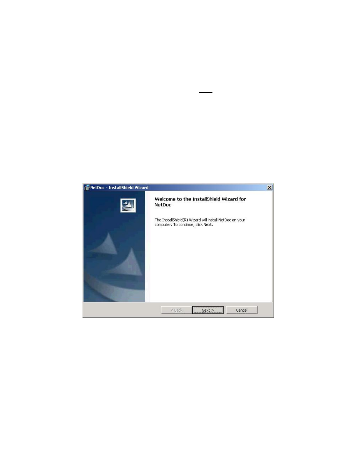
2. Click Install NetDoc. The NetDoc InstallShield Wizard appears, extracting files for the
installation.
3. Click Next.
both MS Windows Server 2000 and
7
Page 14
NetDoc User Guide
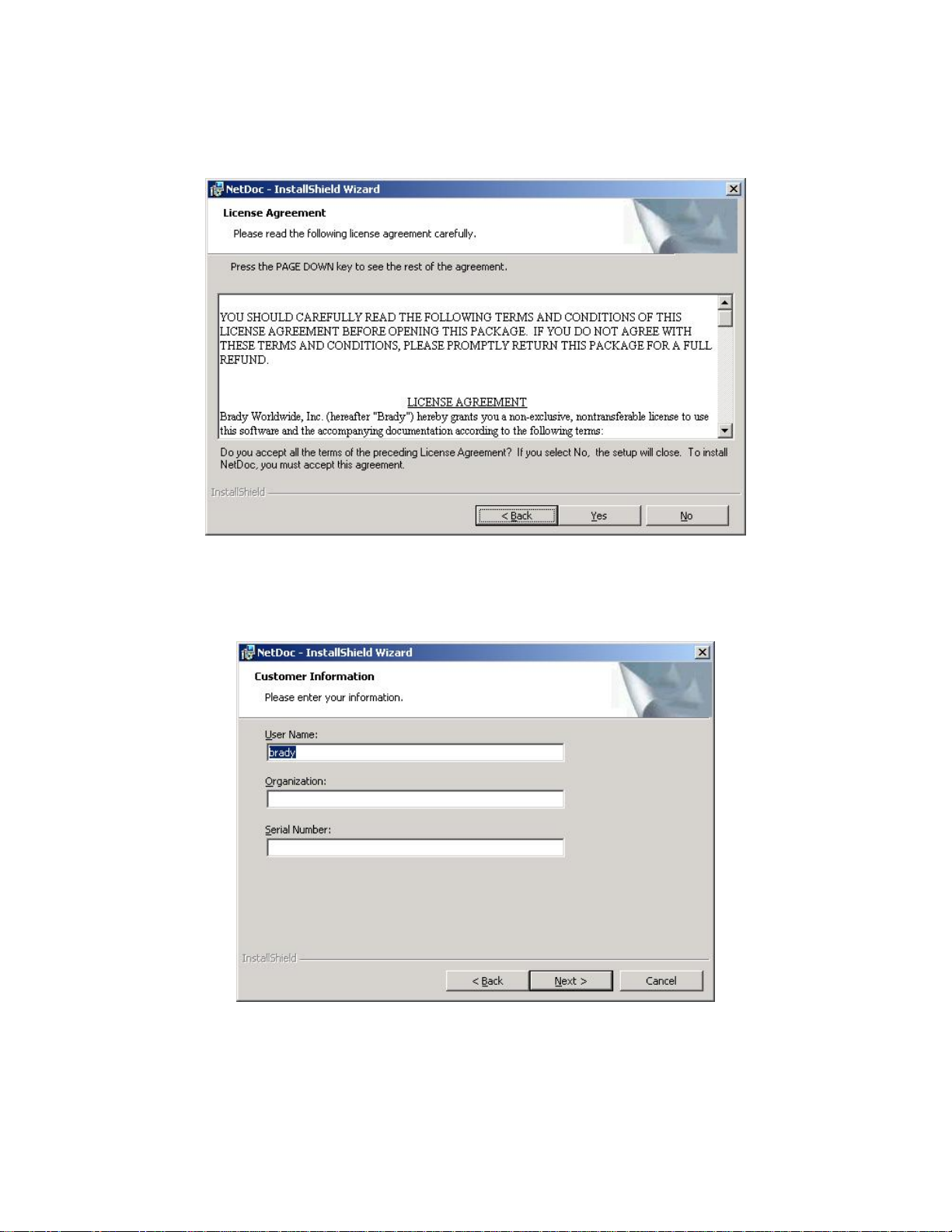
4. When the End User License Agreement (EULA) screen appears, click Yes to accept it. If you decline the
agreement, the software will not install.
5. In the Customer Information screen, enter your User Name, Organization, and Serial
Number (serial number is on the inside cover of the DVD case).
6. Click Next.
8
Page 15
Installing NetDoc
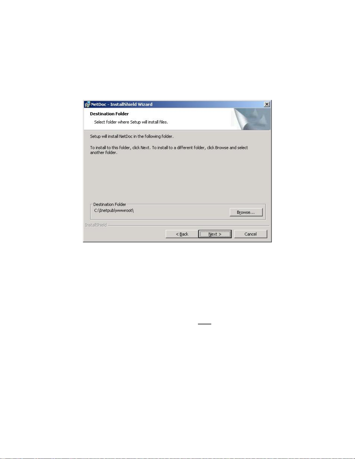
7. The Choose Destination Location screen appears, showing the default directory where
NetDoc will be installed. To accept the default directory, click Next. If you don’t want
to use the default directory, click Browse to select an alternate installation location.
Recommendation: Brady recommends using the default installation directory. Not doing
so may result in additional IIS configuration steps.
8. When the Ready to Install screen appears, click Install. Setup will begin copying files.
9. When the Setup Complete screen appears, click Finish. The setup is complete.
Creating the SQL Server Database
This section steps you through the process of creating the NetDoc server database.
Note: This part of the installation process applies to
2003.
To create the SQL Server database:
1. From the Start menu, choose Programs, then Microsoft SQL Server.
2. Click Enterprise Manager.
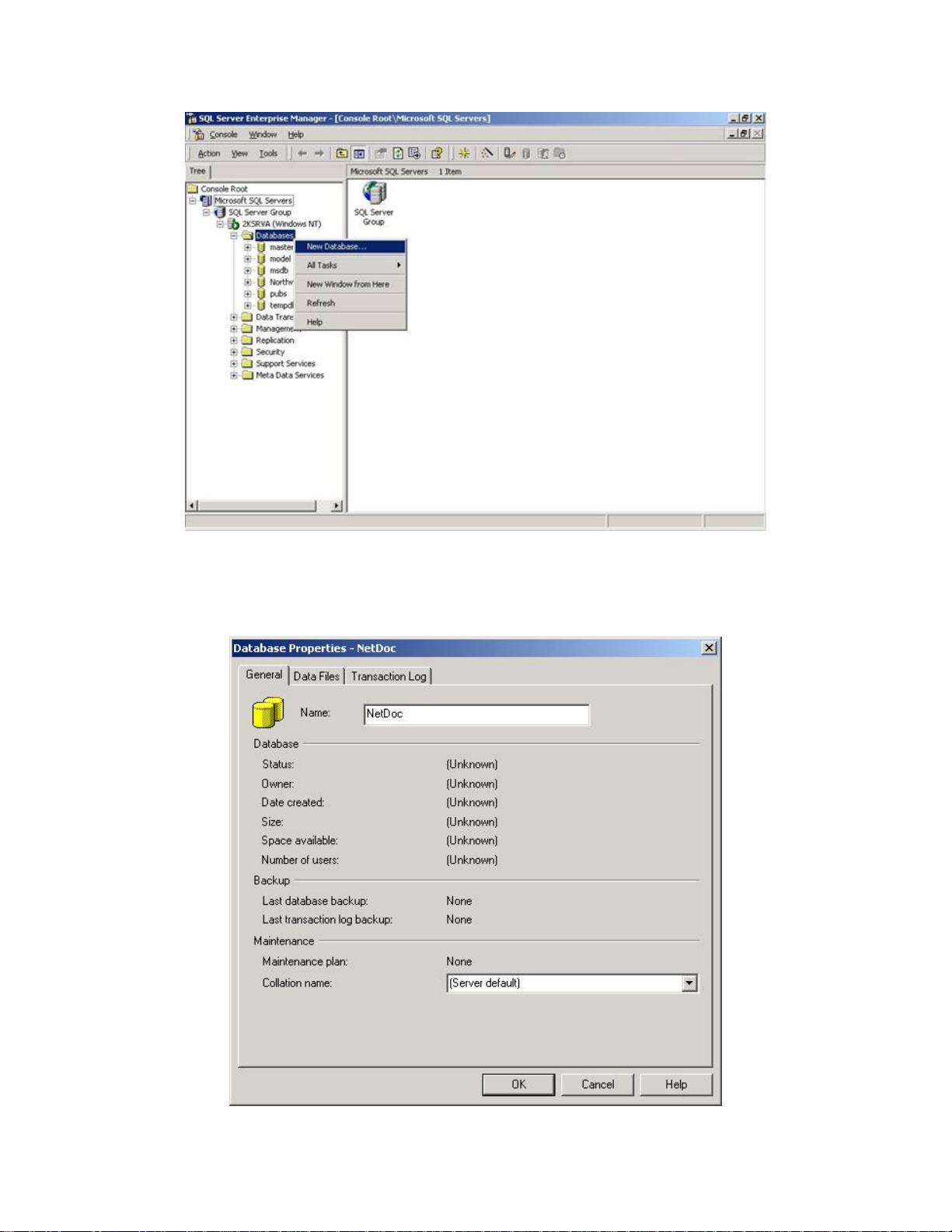
3. In the left pane, expand Microsoft SQL Servers→SQL Server
Group→ <servername> →Databases (as illustrated below).
4. Open the database folder, and either right-click on Databases or choose New Database
from the Action menu.
both MS Windows Server 2000 and
9
Page 16
NetDoc User Guide
5. The Database Properties window appears. On the General tab, enter a name for the
database in the Name field. Make a note of the name, as you will need it later.
6. Click OK.
10
Page 17
Installing NetDoc
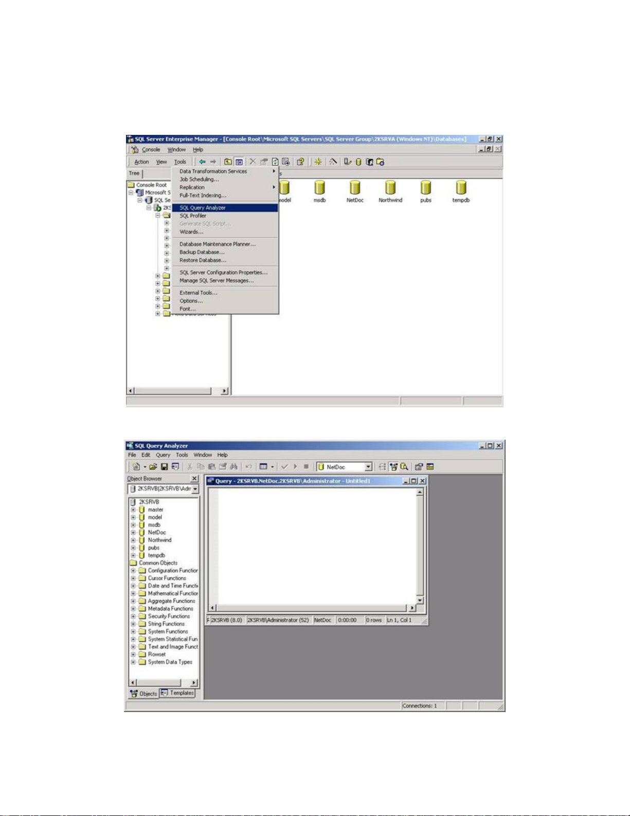
7. Expand the database tree by clicking the plus (+) symbols, and select the database you
just created.
8. Click the Tools menu and select SQL Query Analyzer.
9. Click the File menu and select Open.
11
Page 18
NetDoc User Guide
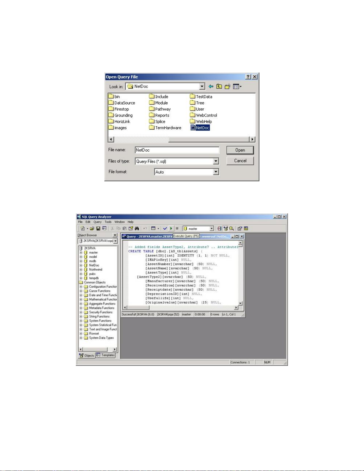
10. In the Open Query File dialog box, browse to the NetDoc installation location you
selected in Installing NetDoc on IIS Server. The default location is:
C:\Inetpub\wwwroot\NetDoc.
11. In the root NetDoc directory, click the NetDoc.sql file, and then click Open.
12. Click Execute Query.
13. Confirm that “Query batch completed” is shown at the bottom of the window. If you
receive an error message, please consult Microsoft’s SQL 2000 Server User Guide.
14. Click Exit on the File menu to close the Query Analyzer.
Note: Please refer to your MS SQL database administration documentation for further guidance
on setting up and configuring your particular MS SQL database.
12
Page 19
Installing NetDoc
Configuring SQL Server Security (optional)
Alert: The following are general guidelines for establishing new database securities within the SQL server. Please
use these instructions as a guideline. A database administrator should perform all SQL configurations for security
purposes.
Note: This part of the installation process applies to both MS Windows Server 2000 and
2003.
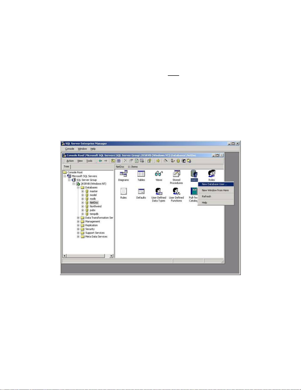
To add the database user in SQL Server:
1. From the Start menu, choose Programs, then Microsoft SQL Server.
2. Click Enterprise Manager.
3. Expand the tree and highlight your NetDoc database.
4. Right click on Users and select New Database User.
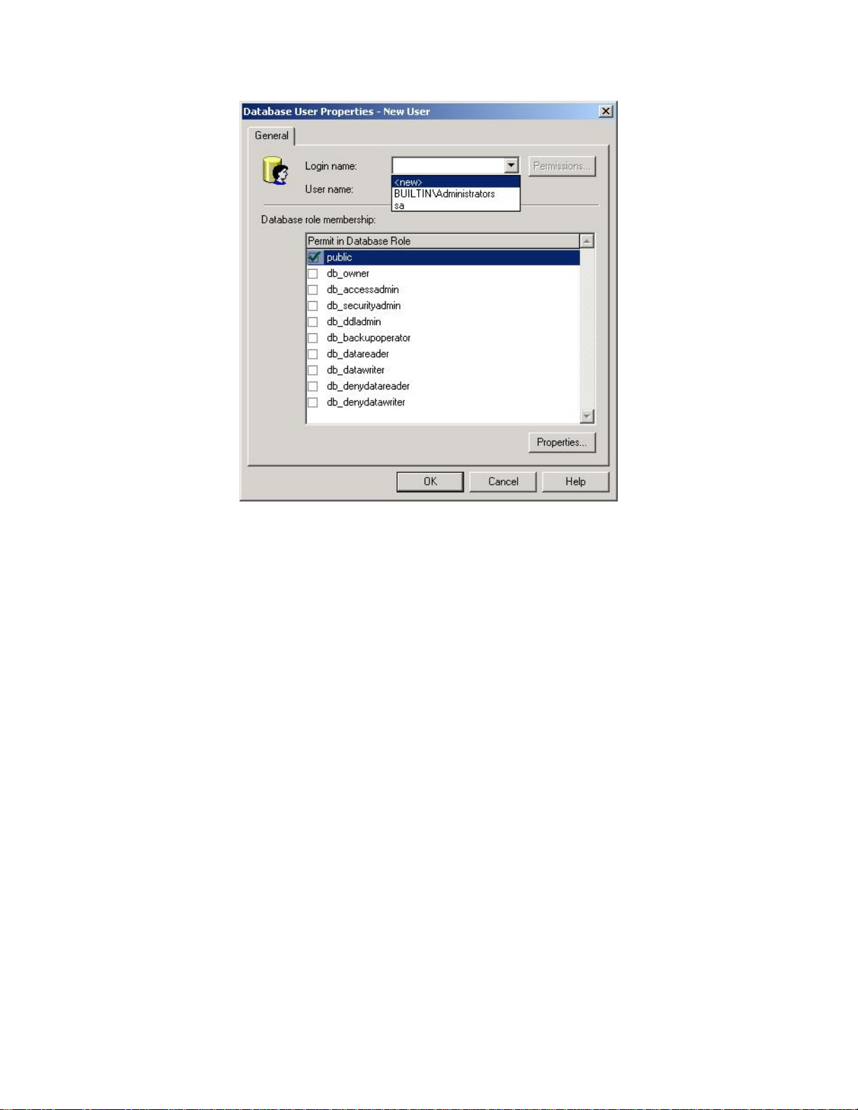
4. In the Login name field, click the down-arrow and select <new>.
13
Page 20
NetDoc User Guide
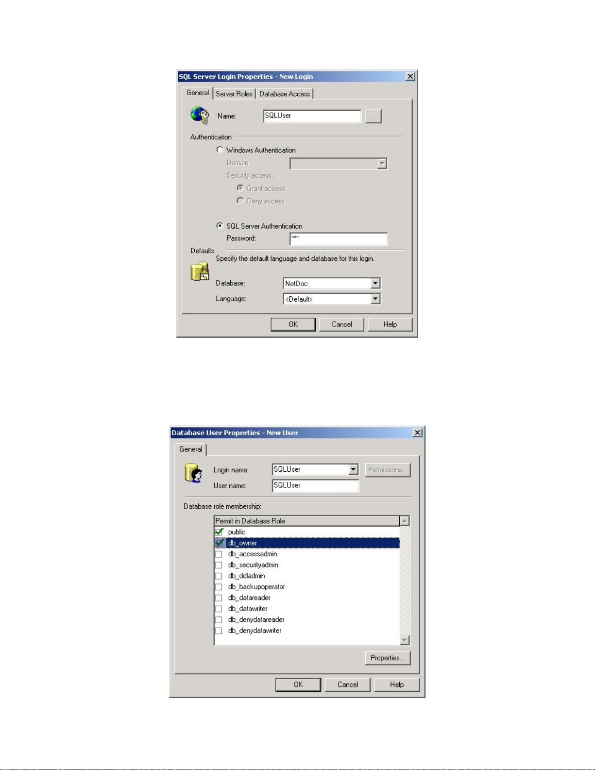
5. When the SQL Server Login Properties – New Login dialog box appears, enter your
new login name in the Name field.
6. Click to select SQL Server Authentication.
7. Enter a password. Make a note of the name and password you entered, as you will need
this later.
8. Click OK.
14
Page 21
Installing NetDoc
9. In the Database User Properties dialog box, click the down-arrow next to Login name
and select your newly added name.
10. Click the checkbox for db_owner.
11. Click OK.
15
Page 22

NetDoc User Guide
12. Your newly added user name will appear in the main pane of the SQL Server
Enterprise Manager window.
13. Close the SQL Server Enterprise Manager.
Configuring IIS to Display NetDoc on an Intranet
This section provides instructions for configuring NetDoc for Windows Server 2003 and Server
2000, and for configuring IIS Security.
Recommendation: Make sure you complete this procedure before attempting to connect to the
database. If you do not configure IIS first, users will be unable to connect to the database (see
Connecting to the SQL Server Database).
IMPORTANT NOTE: For this phase of the installation process, the steps you follow
depend on whether you are using MS Windows Server 2000 or MS Windows Server 2003.
If you are running MS Windows Server 2000, take the steps under
Server 2000.
If you are funning MS Windows Server 2003, take the steps under
Server 2003.
To configure IIS for Windows Server 2000
To configure IIS for Windows Server 2000:
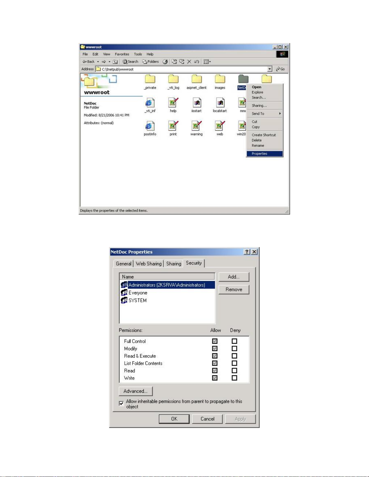
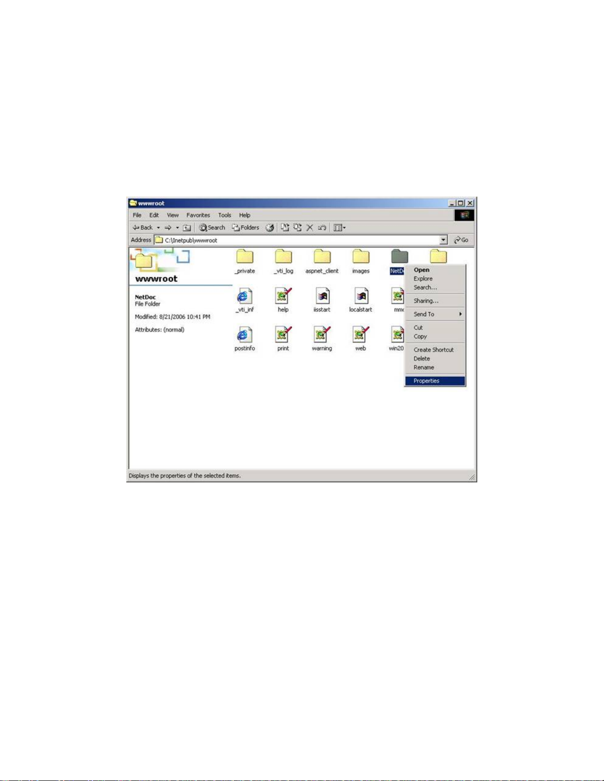
1. Launch Windows Explorer.
2. Browse to the NetDoc installation location. The default location is:
C:\Inetpub\wwwroot\NetDoc.
3. Right-click on the NetDoc folder and select Properties.
To configure IIS for Windows
To configure IIS for Windows
16
Page 23
Installing NetDoc
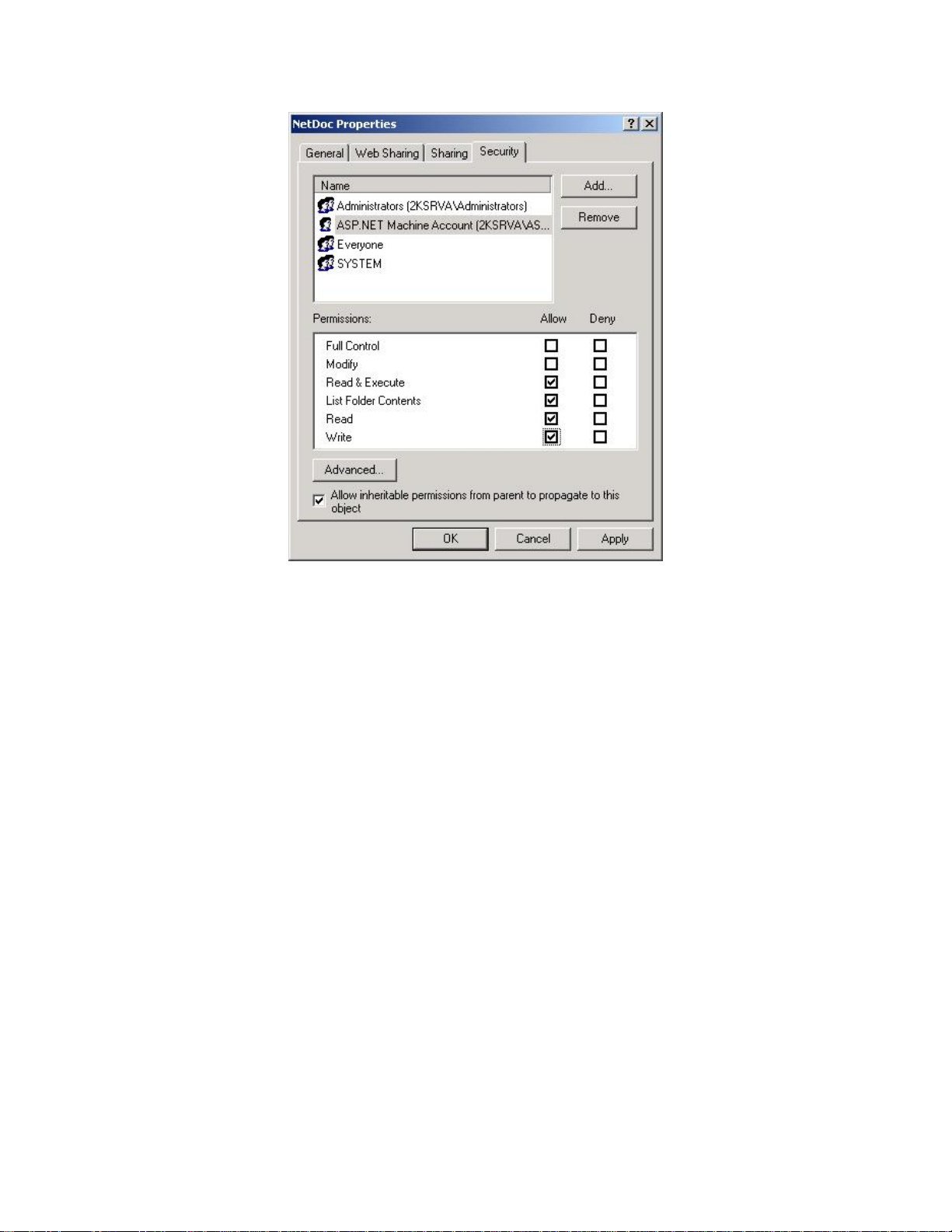
4. In the NetDoc Properties window, click the Security tab.
5. Click the Add button.
17
Page 24
NetDoc User Guide
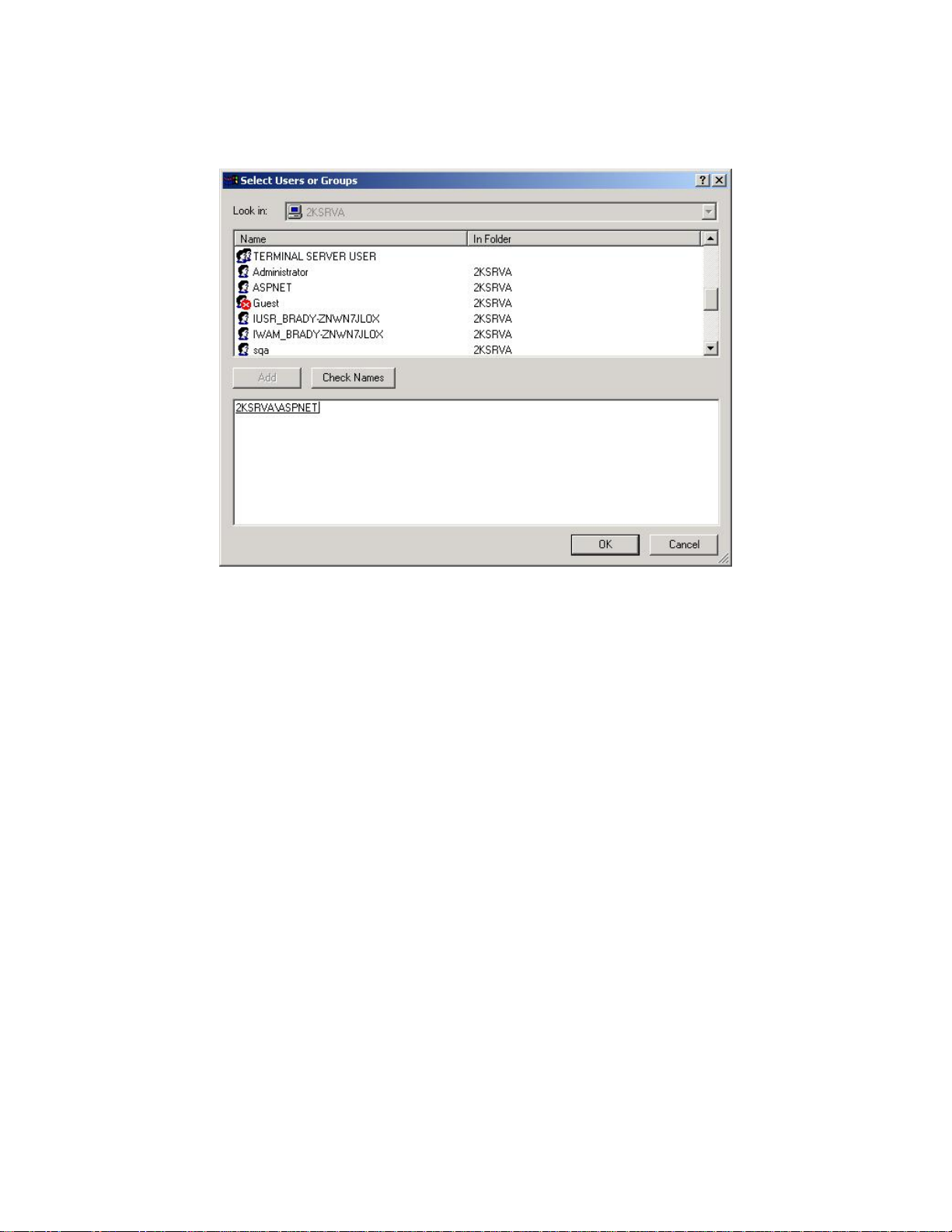
6. In the Select Users or Groups dialog box, select the ASPNET user, and click the Add
button.
7. Click OK.
8. On the Security tab of the NetDoc Properties window, click the checkbox for Write in
the Allow column of the Permissions area.
Recommendation: Deleting an attachment in NetDoc does not remove the attachment from the
hard disk. Granting the ASP.NET user Modify permissions will prevent this from occurring;
however, it may not be considered good security practice. Contact your IT department with any
questions.
9. Click Apply, then click OK.
18
Page 25
Installing NetDoc
10. The folder permissions are configured, and you may close Windows Explorer.
To configure IIS security:
1. From the Start menu, select Control Panel, then Administrative Tools, then Internet
Services Manager.
2. In the tree, locate the Internet Information Services name. Below it should be the name
of your server. Make a note of this name, as you will need it later.
3. Expand your server name, then expand the Default Web Site option. Right-click NetDoc
and select Properties.
4. In the NetDoc Properties window, ensure that Application Protection is set to Low.
5. Click the Directory Security Tab.
6. In the Anonymous access and authentication control section, click the Edit button.
7. In the Authentication Methods dialog box, make sure Anonymous access and
Integrated Windows authentication are check. Everything else can remain as is.
8. Click OK.
9. Click OK again to close the NetDoc Properties window.
10. Close the Internet Information Services window. You are finished configuring IIS
security.
19
Page 26
NetDoc User Guide
To configure IIS for Windows Server 2003
To configure IIS for Windows Server 2003:
1. Launch Windows Explorer
2. Browse to the NetDoc installation location. The default location is:
C:\Inetpub\wwwroot\NetDoc.
3. Right-click on the NetDoc folder and select Properties.
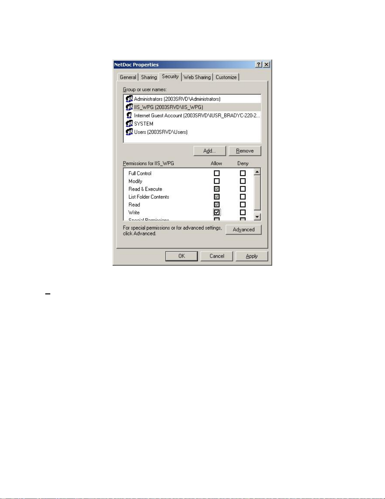
4. In the NetDoc Properties window, click the Security tab.
5. Select the IIS_WPG user.
Note: If the Group or user name list does not include an IIS_WPG user, click the Add
button and select IIS_WPG user from the list. If you cannot locate IIS_WPG user on the
list: 1) click the Advanced tab,2) use the Find Now function to locate it, 3) select it, and
4) click OK. When the IIS_WPG user appears in the NetDoc Properties window (on the
Security tab), select it and continue to the next step.
6. Click the checkbox for Write in the Allow column of the Permissions area.
Recommendation: Deleting an attachment in NetDoc does not remove the attachment from the
hard disk. Granting the IIS_WPG user Modify permissions will allow NetDoc to remove the
file; however, it may not be considered good security practice. Contact your IT department with
any questions.
20
Page 27
7. Click Apply, then click OK.
Installing NetDoc
To configure IIS security:
1. From the Start menu, select Control Panel, then Administrative Tools, then Internet
Services Manager.
2. In the tree, locate the Internet Information Services name. Below it should be the name
of your server. Make a note of this name, as you will need it later.
3. Expand your server name, then expand the Default Web Site option. Right-click NetDoc
and select Properties.
4. In the NetDoc Properties window, ensure that Application Protection is set to Low.
5. Click the Directory Security Tab.
6. In the Anonymous access and authentication control section, click the Edit button.
7. In the Authentication Methods dialog box, make sure Anonymous access and
Integrated Windows authentication are check. Everything else can remain as is.
8. Click OK.
21
Page 28

NetDoc User Guide
9. Click OK again to close the NetDoc Properties window.
10. Close the Internet Information Services window. You are finished configuring IIS
security.
Connecting NetDoc IIS to NetDoc SQL Server
Recommendation: It’s important to disable any pop-up blocker programs. NetDoc may not
function properly with pop-up blockers.
Note: This part of the installation process applies to
2003.
To connect the NetDoc IIS to the NetDoc SQL Server database:
1. Launch Internet Explorer.
2. In the browser address field, type: http://(Server Name)/Netdoc
3. Press Enter or click the Go button in the browser. The NetDoc login website will appear.
4. In the login website, click Select Database.
5. In the NetDoc Data Source window that appears, enter the Server, Database, and User
names (see Add Database User to SQL), and Password. This is the information you
noted earlier when you created the SQL server database and added the database user to
the server.
6. Click Connect. The NetDoc Data Source window will close, and the NetDoc Main Page
will appear, displaying the connected database.
both MS Windows Server 2000 and
Adding NetDoc users
Recommendation: You will need to create a contact before you configure how users log in.
Contacts are users who are able to view the content of NetDoc, and administrators who are able
to add, edit, and delete the information.
Note: This part of the installation process applies to
2003.
To add NetDoc users to view and administer the software:
1. In Internet Explorer, go to the NetDoc Main Page and click Companies under the Setup
menu on the right.
2. In the Company Info page that appears, click the Add button.
3. When the white text box appears, enter the Company Name, Address, City, State, Zip
Code, and Phone Number.
22
both MS Windows Server 2000 and
Page 29

Installing NetDoc
4. Click the Save button, and then close the text box.
5. Click the Launch Application link on the Main Page.
6. When the cable infrastructure screen appears, select Contacts from the drop-down menu
on top.
7. Click the Add button.
8. Your first user should be the overall administrator of the product, who is responsible for
maintaining access to NetDoc. Enter the information for the contact.
9. Create a User Name and Password.
10. Click the Administrator checkbox.
11. Click Save.
12. You can now use this user login information to access NetDoc. Repeat steps 6-11 for
each user.
There are three permission levels for users:
• Admin – Admin checkbox is checked on the Contact screen: User has full
editing rights anywhere in the application, including editing passwords and
password-change requirements.
• Standard – Read Only checkbox not checked on the Contact screen: User may
view and edit component information in existing infrastructures. The user may
not access any of the Setup functions, User Defined Fields, Custom Fields,
Security Log, or password view/edit functions on the Contact screen.
• Read Only – Read Only checkbox checked on the Contact screen: User can view
all data (except password information on the Contact screen), but has no
copy/add/delete/edit capabilities anywhere in the application.
13. Close Internet Explorer.
Configuring Security for NetDoc Login (optional)
There are three basic options for configuring the way users log into NetDoc:
No login (None)
NetDoc controlled login (Forms)
Windows/NetDoc controlled login (Windows).
Recommendation: For ease of use, Brady suggests using the Forms option for Authorization
Mode and Authentication. This will allow NetDoc to manage the passwords.
23
Page 30
NetDoc User Guide
Configuring security requires three settings to reflect the correct mode:
Authorization Mode
Authentication
User Access
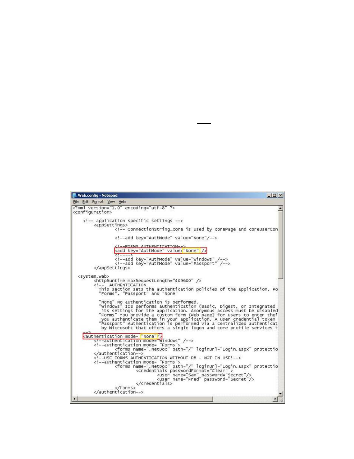
These settings already exist in lines in the Web.Config file shipped with the software. (The file
can be found in the root of the directory where it was installed.)
Note: This part of the installation process applies to
both MS Windows Server 2000 and
2003.
To access the settings:
1. Open the Web.Config file using Notepad or any other text editor.
2. Locate the lines highlighted in the illustration below.
Warning: Authentication Mode values are case sensitive.
24
Page 31

Installing NetDoc
Following are the settings and user types, and instructions for accessing and implementing
settings correctly:
None – Users are not required to log into the system, and no user information is tracked
when attaching files or creating notes. The application is open for read/write on all pages
at all times
Forms – Users are prompted to log in with a NetDoc specific login page. The user
name/password is authenticated against the NetDoc user table. At least one Admin user
must be created initially in 'None' security mode. Subsequent users can be created by any
Admin user of NetDoc. Non-Admin users can create users, but they cannot assign user
names or passwords to allow those users access to NetDoc. A contact created by a NonAdmin must have a user name and password subsequently assigned by an Admin. In
addition, Non-Admin users cannot change their own passwords; an Admin must either
make the change or check the "Force change on next login" box to require the users to
change it themselves.
Windows – Users are authenticated using a Windows Domain Controller. If they are not
authenticated they will be prompted with the standard Windows Login screen. If they fail
to log in, access will be denied. Once authenticated, NetDoc will compare the Windows
user ID to the user ID in the NetDoc user table. If a match is found, the user is considered
authenticated and granted the rights as outlined in the Contact screen.
25
Page 32

Upgrading from an Earlier Version of NetDoc
If you already have NetDoc version 1.0 installed, the process of upgrading to version 1.1 is fast
and straightforward.
Note: Before you upgrade, verify that you meet the minimum hardware and software
requirements for both the server and client workstation machines. (See
To upgrade to NetDoc v1.1:
1. Insert the NetDoc v1.1 CD into the CD-ROM drive of the IIS server on which NetDoc is
installed.
2. The install server screen should appear. (If the install does not start automatically, select
Run from the Start menu, type D:\setup.exe, and skip to step 3.) Click Install NetDoc.
System Requirements.)
3. When the InstallShield Welcome screen appears, click Next.
4. When the End User License Agreement (EULA) screen appears, click Yes to accept it. If
you decline the agreement, the software will not install.
5. When the Ready to Install screen appears, click Install. InstallShield will.
• Remove the old NetDoc files (excluding the Web.config file and the Attachment
directory).
• Install the new NetDoc files.
6. When the Setup Complete screen appears, click Finish to complete the upgrade process.
26
Page 33

Exploring NetDoc
Exploring the NetDoc Environment
The NetDoc interface is comprised of several helpful sections. In keeping everything uniform,
the actual look of the software will remain the same throughout the different sections of the
application. By reviewing the layout of the interface, one can see a navigator, a spreadsheet view
area, a detail section, a locator area, and helpful links all from the uniform exploration view. This
environment was built to satisfy all your documentation needs while remaining easy to use and
navigate.
The NetDoc Main Page
When you login to NetDoc, the first screen will be the Main Page. The Main Page is the entry
page to access all of NetDoc’s features. Every additional page you view in NetDoc has a link
back to the Main Page to make it easy to navigate between the application itself and NetDoc’s
setup tools and reports. The Main Page link is located near the top right-hand corner of all
NetDoc screens.
Links from the NetDoc Main Page
The Main Page links are located in two places:
Under the “Welcome” message on the left side
In a column of five menus along the right side
The left side of the Main Page displays the user name of the individual who logged in, as well as
the name of the database NetDoc is currently connected to.
27
Page 34

NetDoc User Guide
Select Database: If you have access to more than one NetDoc database, you can switch to a
different database by clicking this link. A pop-up window will open where you can enter the
information required to access this database.
Logout: This link logs you out of NetDoc.
NetDoc Main Menu
The NetDoc Main Menu is on the right side of the Main Page and consists of five submenus.
Following is a brief description of each menu link:
NETDOC menu:
Launch Application —
Launches the main NetDoc
function of documenting your
network components.
Help — Opens the online help
feature.
About — Provides the NetDoc
version number.
REPORTS menu:
Report Creator — Opens a
pop-up window from which you
can generate a variety of reports.
TOOLS menu:
Export to LabelMark —
Opens a pop-up window from
which you can export identifiers
created and documented within
NetDoc into the LabelMark
software package for label
creation..
Import Tester Data — Opens
a pop-up window from which
you can import test data in CSV
file format.
User Defined Fields —
Opens a pop-up window where
you can view and edit userdefined fields that appear in
NetDoc component detail views.
Custom Fields — Opens a
pop-up window where you can
add, edit, and delete fields
28
Page 35

you’ve added for component
tracking purposes.
Security Log — Opens a popup window showing the user
transaction log.
WIZARDS menu:
Each link opens the componentspecific auto-numbering wizard
allowing users to create multiple
identifiers of documented
records with the same default
information at the same time.
SETUP menu:
Companies — Opens a pop-
up window where you can add,
edit, or delete Companies in
your documentation.
Infrastructure — Opens a
pop-up window where you can
add, edit, or delete items
documented at the Campus,
Outdoor Space, Building, Floor,
Indoor Space, Faceplate, and
Port infrastructure levels.
Enable/Disable Features —
Opens a pop-up window where
you can hide or show certain
sections of the application.
Exploring NetDoc
29
Page 36

The NetDoc Environment
Navigator Tree
The Navigator Tree, displayed in the upper left pane of the NetDoc application, shows the
physical and geographical layout of your infrastructure. It allows you to move around the
infrastructure quickly and efficiently. You can go anywhere within it no matter how complex
your infrastructure, e.g., to a faceplate in a work area, or to a telecommunication space.
The Navigator Tree functions similarly to Microsoft’s Windows Explorer. Click the + plus sign
at the Company level, and the next level—the Campus level—is displayed. This convention is
followed throughout the Navigator Tree's hierarchy. Click the + sign (which changes to a minus
sign) to display the next level on the tree.
Click the Company icon or anywhere on the Company name, and the List View and Detail
View areas are populated with information filtered according to the selected category.
For example: If you click the Company icon, and then click the Assets selection in the
drop-down field, all assets for your company are displayed in the List View spreadsheet.
Click a building icon or a floor icon, and you will see assets specific to that building or
floor.
The Navigator Tree is easy to set up, using the Company and Infrastructure setup functions on
the Setup menu on the NetDoc Main Page. Once the tree is set up, any change, move, upgrade,
or addition is easy to locate and perform.
See
Hierarchy Descriptions for further explanation and navigation assistance.
Hierarchy Descriptions
The hierarchy layout in the Navigator Tree is set up as follows:
Company
Campus
Outdoor Space
Building
Floor
Indoor Space
Faceplate
30
Page 37

The NetDoc Environment
Company – The company is the highest-level component in NetDoc. It's the starting point
for managing your cabling infrastructure. Even if you only manage the infrastructure for a single
company, you still need to define the company before setting up cabling infrastructure.
Campus – Your company may have only one location, and in that case you would create
only a single campus. But many companies conduct business in a number of locations. The
campus feature in NetDoc makes it possible to manage infrastructure specific to each location.
Outdoor Space - You can also set up an outdoor space such as a Manhole or a Utility Pole.
After spaces are in place, you can start to specify cabling and hardware.
Building - Each campus you set up will include buildings that contain spaces that house
components of the infrastructure. Your company may have one building, or numerous buildings
that can be interconnected by cabling components.
Floor - Floors in buildings are the next level of geographical infrastructure you create in
NetDoc.
Indoor Space - In NetDoc, a Room, Telecommunications Space, Cubicle, Hallway,
Warehouse, Kitchen, or Office is considered to be an Indoor Space.
Faceplate - While many elements of cabling infrastructure can be added at any time after the
geographical infrastructure is set up, Faceplates should be set up first. Faceplates are usually
attached to a Work Area such as an office.
Whatever level of the Navigation Tree you select is highlighted. In addition, when you let your
cursor hover any item on the tree, a floating box will open with the name and type of
infrastructure item. If the item is a Faceplate, the box will also include the ports connected with
it.
Location Info
The Location Info section is directly beneath the Navigator Tree on the left side of the NetDoc
screen. No matter how elaborate your infrastructure, the Location Info section displays where
you are according to your highlighted selection in the Navigator Tree. See
Descriptions.
Hierarchy
List View
The upper half of the right pane is the List View. Also referred to as the List View pane or List
View area, it resembles a spreadsheet. Clicking any category in the drop-down list in the upper
left corner of this pane displays a list of records in the chosen category for the Navigation Tree
level you’re at. The drop-down list includes the following infrastructure categories:
All items
Assets
31
Page 38

NetDoc User Guide
Termination Hardware
Horizontal Links
Backbone Cables
Pathways
Firestops
Grounding
Splices
Contacts
Your location in the Navigator Tree filters the records seen in the List View pane.
For example: If you are at the building level in the Navigator Tree, and have selected Horizontal
Links in the drop-down field, you will see all the records for Horizontal Links within that
building.
Clicking a column heading sorts the records by that column in ascending order; clicking on the
column heading again will sort it in descending order.
For example: If you select Horizontal Link and then click on the Cable ID column, the
horizontal links are sorted in ascending order according to Cable ID. An up-arrow appears next
to the column heading indicating that the list is sorted in ascending order. Click again and the
arrow points downward, indicating the records are sorted in descending order.
The first column of the List View pane consists of a clickable button that allows you to display
the detailed view for that component in a pop-up window. This lets you have side-by-side views
of components, which you can minimize, expand, and move around on your screen. It also
allows you to move to another section of NetDoc while keeping the detailed-view pop-up
windows open.
Following are the user buttons along the top of the List View pane:
The Copy button will allow you to duplicate the item being copied
for an easier way of building specific network components.
The Add button allows you to create a new record in whichever area
you have selected.
The Delete button allows you to delete a record.
32
The To Clipboard button copies whatever information is in the
current table to the computer’s clipboard for pasting into any other
application.
The To Excel button opens a browser window with the data in the
table formatted as a Microsoft Excel spreadsheet. You can print it or
Page 39

Detail View
The NetDoc Environment
save it as an Excel file.
The Print Details button enables you to print details of an individual
record (i.e., not everything in the list) as an HTML-formatted report
in your Internet browser.
The Search button opens another window containing the records
currently in the List View table, where you can enter a search string
and initiate a search of the records in the table.
The Previous and Next buttons allow the user to navigate between
pages of spreadsheet views.
This section also serves as a counter for the number of items
viewable within a selected area.
When a List View category is selected, the Detail View in the lower half of the window displays
details of the selected record from the List View table. You can change to a different record by
selecting a different row in the spreadsheet, either by scrolling down through the records using
the arrow keys or clicking on a record with your mouse pointer. The Detail View display is
linked to the selection chosen in the List View.
For example: If Termination Hardware is selected, the Detail View shows tabs Termination HW
Info and Port/Pos. Details. The tabs shown in the Detail area will change according to the
category selected in the drop down field, and sometimes will even change in the same category
but with different types. This will occur throughout the application as the tabs are associated and
used for each category and for the different types of items in those categories.
When an item in the List View area is selected, the Info tab in Detail View always gives detailed
attributes of the selected record. The remaining Detail View tabs usually show information about
how that record is connected to other cabling elements.
For example: When selecting a record on the Horizontal Links (HL) drop-down list in the List
View, the Detail View tabs have specific data about the horizontal link:
The Hardware Sequence tab shows the hardware sequence for the selected cable.
The Connected Backbone tab lists backbone cables connected to the HL and permits the
user to connect backbone cables to that horizontal link.
The Pathways Used tab does the same for Pathways containing HLs.
The Notes and Attachments tab shows all associated notes to the selected cable and all
attached items.
If the horizontal link is a voice link, an extra tab exists called Key Sheet that contains
data input by the user about the phone connection.
33
Page 40

NetDoc User Guide
If the Horizontal Link category is selected, and you change to a different space on the
Navigator Tree, the information populating the List View and Detail View will change as you
move to the different space. If, for example, you move up to a higher level on the tree, all the
horizontal links for that level and space are shown in List View. Detail View will contain details
of the first record in that group by default, or the last record you highlighted.
Attachments
NetDoc has attachment capability that can be found throughout the application. This capability
can be found at every level of your infrastructure, along with everything being tracked about
your infrastructure, down to each individual component. An attachment can be added at any level
to better enhance your documentation needs.
An attachment may be any file needed to better illustrate needed information about your
network. These attachments may be network drawings, digital photos, MS Excel documents, MS
Word documents, and more. By using this capability and using it correctly, your documentation,
network drawings, photos, and all other needed files are stored in one easy-to-reach location.
To add an Attachment:
1. In the Attachment area, click Add.
2. In the Attachment pop-up window, click Browse to locate your attachment.
Note: You may type specific comments within the pop-up window.
3. Click OK to close the Attachment pop-up window. Once the pop-up window closes, the
attachment will be located in the Attachment area with a Time/Date/User stamp on it. A
message stating “Attachment successfully attached “ will appear. Click OK.
4. Click the Save button so all attachments and changes will be saved correctly.
Note: If an attachment is given an identical name of one already added in the same section of
NetDoc, the second attachment will not be saved, even if the first attachment had been deleted.
If this occurs, choose a different name for the attachment file.
To view an Attachment:
1. Locate your attachment within NetDoc.
2. Click on the View link next to your attachment. The file will launch in an HTML-
formatted window.
3. Close the HTML window when you have finished viewing the file.
To delete an Attachment:
1. Locate your attachment within NetDoc.
2. Click on the Delete link next to your attachment for complete deletion of the file.
34
Page 41

The NetDoc Environment
3. Click OK on the pop-up message that appears when you are positive that deletion of the
selected note is needed.
4. Click the Save button once deletion has completed to save and update all components.
Note: Deleting an attachment does not delete the file from the NetDoc server; it only deletes its
connection to the NetDoc component.
Notes
NetDoc has Notes capability located throughout the application. This capability can be located at
every level of your infrastructure and also within the Notes and Attachments tab in the Detail
pane for every component being tracked. Beyond these areas of the application you can also
attach notes down to the port level of a piece of hardware and also down to the strand level of a
cable for example. With this capability, individuals can relay information to others and save
specific needed notes for future use. By using this functionality, your notes can assist all users in
recalling needed information and also better document your network by providing additional
space for valuable information.
To add Notes:
1. Within the Notes area of the application, type your notes into the given Notes box.
2. Click Save in order for your notes to be saved properly.
After the Save button has been clicked, your entered note will move below the Notes box. The
newly created line with your entered notes will also contain a Time/Date/User stamp.
To add additional Notes to the Port or Strand Level:
This capability can be found in both the hardware or backbone cable portion of the application.
• In the Termination Hardware area under the Port/Position tab this capability will be
found down to the Port/Strand level.
• In the Backbone Cables area under the Pair/Strand Details tab this capability will be
found down to the Pair/Strand level.
Within these tabs, to the far right of each row will be a Notes column.
1. Click on the selection button for the item needed to receive a Notes pop-up window.
2. Type in the needed notes and click OK to close the pop-up window.
3. Click Save in order for your notes to be saved properly. Once you have clicked the Save
button, a check mark appears in the selection box illustrating a saved note for that item.
Note: At this level, notes can be deleted or changed by going through the same Steps 1-3 as
stated above. No additional links will be found at this level, since all capability is specific to the
level being reviewed for the component in question.
35
Page 42

NetDoc User Guide
To delete Notes:
1. Locate your Notes within NetDoc.
2. Click on the Delete link next to the Note(s) you want to remove for complete deletion of
the attached Note file.
3. Click OK on the pop-up message that appears to complete deletion of the selected note
4. Click Save to save and update all components once deletion has been completed.
Revision Log
At every level of the infrastructure, each component’s Detail View lists the user name of the
individual who added the component to the structure and the date/time stamp of when it was
added.
Any changes made to this component’s documentation in NetDoc are tracked, and the last
change made is also noted by user name and date/time stamp on the Detail View.
The Revision Log is view-only for administrator-level access; no fields can be changed.
36
Page 43

NetDoc Tools Available Within the Application
Multi-View Multi-Task Capability
NetDoc has the ability to allow for multi viewing and multi tasking while navigating throughout
the application. Within the application launch and in the spreadsheet view, each row will have a
button to the far left of each row in every single area of the application. If this button is selected
a pop-up window will appear displaying the Detail area for the item selected. The User can then
open another item for side-by-side comparisons as needed. You are not limited to the same area
as a user may open a piece of hardware, minimize that screen and then open a backbone cable
using the same technique for comparison viewing of those two items.
Pop-up windows are an essential part of NetDoc and will not limit but instead enhance your
working capability. When any pop-up window appears that may be needed a short while later,
you can minimize the screen and continue working and then restore the screen again without
having to return to where the screen was originally accessed. For example, you can go to the
home page and click on Report Creator, then minimize the creator screen and launch the
application to continue working. After a while you may need another report, so you simply
restore the screen to create the report without having to go back to the home page to gain access
to this tool. This NetDoc feature saves time and makes the application easier to use.
Window Sizing
NetDoc allows for the different areas of the main screen within the normal application view to be
resized as the user sees fit. After clicking on the Launch Application link on the NetDoc home
page, the screen will be divided into four key areas: the Navigator Tree, the Location Info area,
the List area, and the Detail area. The user can utilize NetDoc’s grab-and-drag capability by
placing the mouse pointer over any of the dividing lines between these areas and holding it
down. Many users enjoy viewing several items in a spreadsheet view and can do so by grabbing
the dividing line between the List and Detail areas and dragging it down to multiply the number
of items accessible in the spreadsheet view.
Note: These areas can be resized repeatedly and manipulated according to user need.
Search Function
Records shown in the List View table of the NetDoc window can be searched across multiple
fields, using whatever search text you enter.
To use the search function:
1. In the Navigation Tree, highlight the level of the records you wish to search for (e.g.,
Company, Building, Floor, etc.).
2. In the List View, select from the drop-down category list to choose the records to search.
3. Click the Search button above the table.
37
Page 44

NetDoc User Guide
4. A separate window will appear containing the records of the infrastructure level and
category you already chose. In the Search Text box, enter your search string.
5. Click the Search button.
6. The data in the table will change to display only those records containing your search
text. (If there are no records with that text, a message box will alert you.)
Note: From the search window, you can change the component category from the drop-down
list and perform another search. However, to change the level on the Navigation Tree, you must
return to the NetDoc window and highlight the new location on the Navigation Tree.
From the search window, you can also:
Copy the table data to the clipboard for pasting in another application.
Export the table data to a Microsoft Excel spreadsheet.
Print the detail report for the currently highlighted item in the table.
Use the standard table sorting and item section features available on all NetDoc tables.
Click the box in the first column by any item to open the Detail View for that item and
make any changes.
Quick Set/Quick Insert Buttons
Throughout NetDoc where you choose a location for a component or, in the Cable Path, where
you insert a component, you will find these shortcut buttons that allow you to quickly choose a
location:
When you click on the Quick Set or Quick Insert button, the Navigator Tree is highlighted (its
background turns blue), and you can simply click on the location on the tree to incorporate the
information for that location into the component’s detail record.
View Most Recently Added Items
Many fields in the Detail View in NetDoc have a Recent button next to them. When you place
your cursor over this button, a floating window will appear that displays:
The 10 most recently modified items in that component category, and the date each was
modified
The 10 most recently added items in that component category, and the date each was
modified
This information is particularly helpful when adding or modifying component information.
38
Page 45

NetDoc Tools Available Within the Application
Copy Capabilities
NetDoc provides several options for copying existing data to other locations in NetDoc or to
entirely separate applications, such as Microsoft Excel and Word. These copy capabilities are
always available in the List View pane and can be used by clicking on any of these three buttons:
Copy
To Excel
To Clipboard
Copy Button
NetDoc's Copy capability is a great time saver available throughout the application. This feature
is always located in the List View pane and can be used by clicking on the Copy button. If used
properly it will minimize typing time and user errors. The Copy capability allows a selected item
to be completely copied into the Detail View area, where you can then modify any information.
This is especially helpful for creating new components that closely resemble already-built
components.
To use the Copy function:
1. In the List View, select the component you wish to copy.
2. Click the Copy button.
3. A **new record** row will be added to the List View table, and the data you copied
will be displayed In the Detail View pane, where you can now make the necessary
changes in the specific fields.
4. When you've finished with your changes, click the Save button above the Detail View
pane. The component information you just copied and modified will fill in the **new
record** row on the List View table.
Note: Ensure that before saving the newly duplicated item, you change all fields that must be
unique from the copied original. NetDoc will display messages above the Detail View when you
save the copied data without making the necessary changes to those fields, and you cannot add
the new record until you make the required changes.
To Excel Button
The Copy to Excel feature allows you to export the entire spreadsheet in the List View directly
to Excel.
To copy to Excel:
1. With the information you want to copy displayed in the List View table, click the To
Excel button.
39
Page 46

NetDoc User Guide
2. An Excel file will open with all the List View data displayed just as it is in NetDoc. You
can now modify it, save it as an Excel spreadsheet, print it from Excel, and so forth.
To Clipboard Button
The Copy to Clipboard feature allows you to copy the entire spreadsheet in the List View to your
computer’s clipboard, from where you can paste it into any other application.
To copy to the clipboard:
1. With the information you want to copy displayed in the List View table, click the To
Clipboard button.
2. Open the application (e.g., Word, Lotus, etc.) you wish to paste the information into.
3. In the application, choose the Paste function. All the data in the current List View
spreadsheet will be copied as rows of text in that application, and you can save it in that
file format, modify it, print it, etc.
Circuit Trace Tool
About the Circuit Trace Tool
NetDoc’s Circuit Trace Tool allows you to view, in both text and graphic format, all the
components of an individual circuit. Circuit tracing is especially helpful in identifying the
source of a problem in the network or in viewing a circuit in diagram form.
With the Circuit Trace Tool, you can:
Choose a port or pair/strand and view a table listing details of its circuit infrastructure.
View a modifiable graphical diagram of the circuit infrastructure.
Click to change the trace point, and thus the table and diagram information.
Print the detailed information and graphical diagram.
Accessing the Circuit Trace Tool
The Trace Tool is accessible from four Detail View screens within NetDoc:
Ports tab of the Assets Detail View
Port/Position tab of the Termination Hardware Detail View
Pair/Strand Details tab of the Backbone Cables Detail View
Cross Connects tab of the Backbone Cables Detail View
To access the Circuit Trace Tool:
1. From the NetDoc Main Page, click Launch Application.
40
Page 47

NetDoc Tools Available Within the Application
2. Highlight the trace point component in the List View.
3. In the Detail View for that component, click the appropriate tab:
Assets: Ports tab
Termination Hardware: Port/Position tab
Backbone Cables: Pair/Strand Details tab or Cross Connects tab
4. Click the box in the Trace column for the component whose circuit you wish to view. A
separate window will open displaying the details in table and graphic formats.
Viewing Circuit Information
The Circuit Trace window consists of two main elements:
A table that lists the detailed location of each component in the circuit. The highlighted
item in the table that is the component from where the trace is being conducted. The
other items show the circuit in both directions until the endpoints.
A graphical diagram with each component and connection illustrated. Each graphic also
displays the ID of the component, a link to view the Navigation Tree showing its location
(hardware only), and links to view all the ports or pairs/strands connected to that
component — both taken and available. Lines linking the images indicate how the
components are connected, with bolder lines indicating a cross-connection at that point.
Show/Hide Table or Diagram
To hide either or both the table or diagram, click the Hide Table or Hide Diagram link.
When hidden, the link will change to Show Table or Show Diagram. To redisplay that
element, click the Show Table (Diagram) link.
Invert Table
To show the components listed in reverse order on the table, click the Invert Table button.
(This only changes the order of the table — not the diagram.)
Copy to Clipboard
To copy the information in the table to the clipboard for pasting into another application, click
the Copy to Clipboard button. (Only the table is copied — not the diagram.)
The print function will send to the printer whatever is currently displayed in the Circuit Trace
window.
To print the circuit trace information:
1. Make sure the elements you want to print (table and/or diagram) are showing in the
window.
41
Page 48

NetDoc User Guide
2. Click the Print button.
Arranging the Diagram
The default arrangement for the graphic diagram is a straight line from left to right. You can
change it to one of three other arrangements, or you can manually rearrange the components.
To change the structure of the diagram:
1. Place your mouse over the Arrange link to open a floating menu.
2. Click on one of the structures shown in the menu. The images and connecting lines will
change to reflect that structure.
- OR -
1. Rearrange the diagram manually using the drag-and-drop function to move the images
around on the screen. The connecting lines will automatically move with the component
illustrations. This capability is often used to arrange the components to replicate their
actual physical layout.
Note: A manual rearrangement of the diagram remains only while you keep the window open.
Once you close that Circuit Trace window, the diagram will resume the default structure.
Viewing a Component’s Detail
From the Circuit Trace window, you can open a pop-up window displaying the Detail View
information for any component shown in this window.
To view a component's Details View information:
1. Click the component’s ID link in the box containing its illustration.
2. A pop-up window will appear, displaying the Detail View for that item.
Changing the Trace Point
You can change the trace point from within the diagram by choosing another port or pair/strand
for any component. This will change the information on the table and the diagram.
To change a trace point:
1. In any of the illustration boxes, click either the ports or pairs/strands link for that item.
2. A drop-down menu of all ports and/or pairs/strands connected to that component will be
displayed, including which ones are taken and which are available. Click on the link for
the one you want to trace from.
3. With the new port or pair/strand as the trace point, the table and diagram will change to
show all components of that circuit to its endpoints.
Note: You can also open a new trace point table/diagram in a pop-up window to see the
different paths side-by-side. To do so, hold down the Shift key as you click on the link in step
2.
42
Page 49

NetDoc Tools Accessed from the NetDoc Main Page
Exporting to LabelMark™
The Export to LabelMark tool can be found on the NetDoc home page. LabelMark™ is a label
design application that interacts closely with NetDoc. By bringing the two applications together,
you conduct the input of information once. By entering identifiers for all areas of your
infrastructure only once, you are able to ensure proper creation of your identifiers and create
labels for those components.
The Export to LabelMark tool passes tracked infrastructure components information and created
identifiers along to the LabelMark application. The exceptional feature of this tool is that the
information and identifiers sent to the LabelMark application are completely defined by the enduser, and once LabelMark acquires these identifiers the user can operate the LabelMark
application as usual, with access to all normal LabelMark functionality for label creation. The
identifiers built within NetDoc and viewed within the NetDoc application become exclusively
available for exporting into LabelMark through the process outlined below.
To export to LabelMark
Click on Export to LabelMark on the NetDoc home page. The NetDoc – Export to
LabelMark pop-up window will appear, with numbered steps displayed.
1. In the Filter by Object drop-down field, select what objects your labels will be created
for. In the Type drop-down field, select the type of objects to create labels for. You can
keep this as All or, depending on the objects you've selected, you can choose from a list
of type options, which will vary based on the objects selected.
2. Click the Set Location button to map through the navigator tree and select the location
where the work is being conducted. Once you select the location, click the Accept button.
The Step 2 fields will automatically populate with the selection made.
3. In the Space Type drop-down field, select a space type. You can keep this as All or filter
down and select specific space(s). The Step 3 window will automatically populate with
the selection made.
4. Click the Preview button. The Step 4 window will display a list of identifiers for review
before the export is conducted.
5. In the Select Fields area, you may select up to three fields in any order to export into
LabelMark. Highlight a selection and click the > button to insert
(the top-most field will appear first on all labels, with the second and third appearing in
descending order).
Note: Click the C button to clear a field and re-enter a selection, or to leave the field
blank.
it into the adjacent field
6. Click the Export button once all five steps above have been completed. This will prompt
NetDoc to locate LabelMark on your client machine.
43
Page 50

NetDoc User Guide
Note: If LabelMark is not installed on the client machine, the export will be aborted.
Once LabelMark is found, the LabelMark window will appear and you can use the fully
functioning LabelMark application to select your printer, label type and size for the
identifiers being created, and more.
Important Note: NetDoc is a web-enabled application, not installed on the client machine;
however, LabelMark is installed on the client side and the Export to LabelMark feature will only
operate on machines where LabelMark is installed.
Additional Note: For older versions of LabelMark, you may have to follow on-screen
instructions to allow for an ActiveX control to process for LabelMark to launch. This will occur
since NetDoc is web enabled and it is attempting to launch the LabelMark application, which is a
client installed solution. With the newest LabelMark solution, a new development will allow
LabelMark to view NetDoc (and vice versa) as a Brady web-enabled safe application. Either way
the solutions will work together, and the on-screen instructions, if shown, will walk you through
the process.
Tester Data Features
About the Tester Data Import Tool
The Import Tester Data tool can be found on the NetDoc home page. NetDoc works with all
testers, with the tester’s test results being accepted in CSV file format. By converting your test
results into a CSV file, NetDoc stores all information in its appropriate location as designated by
the importing user.
The importing of tester results is performed completely through the Import Tester Data home
page link. (See
Importing Tester Data.) On the other hand, when reviewing a cable's test data,
this function is accomplished through the cable end by selecting the View Tester Data button.
(See
Viewing Tester Data.)
When importing your test results, you may save both a Profile Map (optional) and a Set Name
(required).
• A saved profile will save all of your formatted column headers while importing your test
results. Then the next time you import data from the same formatted tester, the previously
saved profile can be selected, eliminating the need to rebuild column headers and keeping
them intact during the import process.
• The saved set name names and saves specific data imported. When a cable is selected for
referencing of test results, the user will be asked for the set name in order to bring up the
corresponding results.
The unique feature about NetDoc’s Import Tester Data tool is that what is imported is completely
definable by the user conducting the import. For instance, the tester may have hundreds of
columns of information, but for the purpose of having the test results in NetDoc you may only
require five columns of pertinent information. NetDoc will allow for this. (See
Importing Tester
Data for more information.) By having this flexibility you will quickly gain access not only to
44
Page 51

NetDoc Tools Accessed from the NetDoc Main Page
test results, but to the relevant information within those results that are specific to your
documentation purposes.
Important Note: It is recommended that all test results be saved and maintained in their original
format outside of NetDoc for any future need. By using NetDoc’s capability you can modify the
amount of information needed for quick reference, but the original formatted results should
always be saved in case they are needed for future reference.
Importing Tester Data
Click on the Import Tester Data link on the NetDoc home page. Numbered steps will display.
1. In the Select space location area, click the Set Location button to map through the
navigator tree and select the location to which the test results should be associated. Once
you select the location, click the Accept button to populate the Space field.
Note: This step is needed for both Horizontal and Backbone Cable test results.
2. In the Select Backbone Cable area, click the drop-down menu and select the Backbone
Cable needed.
Note: This step is only needed if importing test results for a Backbone Cable.
3. In the Select data file to import area, click browse and locate the needed CSV file for
import. Once you have located and selected the file and the link appears in the Step 2
field, click the Open button.
Note: If your test results have leading and trailing quotes – they can be removed by
selecting the check box below the Step 2 field before opening the results for loading.
The word "Loading..." will appear in the bottom portion of the screen. Your test results
should appear within seconds as the system processes the imported file.
4. Click the Add/Remove button. When the Add/Remove pop-up appears you can build
your tester manufacturer. Once completed, click the Close button and make sure the
appropriate name appears in the Step 3 field.
5. Skip the optional next field (Select or Name the Profile Map) and go to the following
field (Step 5 – Add/Remove Column Headers for Data Grid) in the right-hand portion
of the screen). Click the Add/Remove button, then in the All Fields window, highlight
the column headers you want to keep for the final import of information into the
application database. Select the appropriate arrows to move the highlighted headers into
the right side of the pop-up area (these selections will then appear in the expanded Import
screen table).
6. In the Import screen table, click on the drop-down menus and select the header you just
created for placement above the columns that correspond with the data you wish to
import. (Data in columns without a header will not be imported, ensuring your file will
only contain the information you specify for your final import.)
45
Page 52

NetDoc User Guide
7. Click the Save Profile button on the bottom of the Import screen. Your profile name
should now appear in the Select or Name the Profile Map field.
8. Once the above steps have been completed, click the Import button. A pop-up window
will appear. Type in a set name, tested by name, and any needed notes for this test set
being imported. Click Import again and your file will begin the process of importing into
the selected location. A pop-up message will appear once completed, stating a successful
import.
9. Close the import pop-up window or select reset to reset all steps and begin another
import if desired.
Notes:
Make sure the test data includes the HL ID you have assigned in NetDoc. You will be
able to enter that ID in the tester machine.
You must specify the correct HL ID in the tester, or the test data will not be found when
you look for it in NetDoc.
NetDoc will not reformat the tester-machine data. The data will be in the format exported
by your specific tester machine.
See also
Viewing Tester Data.
Viewing Test Data
To view test data:
1. Click the Launch Application link on the NetDoc Main Page.
2. From the List View drop-down menu, choose the category.
3. On the table, highlight the item whose test results you wish to view.
4. In the Detail View area, click the View Test Data button.
5. A pop-up window will appear. Select the Set Name for the test results being referenced.
6. The window will display the test results imported under the referenced set name. At this
point, you can print the test results by clicking the Print button, or close the window.
See also
Matching Tester Data.
Matching Tester Data
If your Cable ID in NetDoc matches the Cable ID in your imported Test Results, the application
will find them (if a complete match) once you click on the Set Name for viewing tester data (see
Viewing Tester Data).
Note: The cable should highlight and be located automatically. If your Cable ID does not match
any of the Cable IDs imported, the set will still appear, but a message will pop up stating that the
cable ID could not be found.
46
Page 53

NetDoc Tools Accessed from the NetDoc Main Page
See also Deleting Imported Tester Data Sets.
Deleting Imported Tester Data Sets
To delete imported tester data:
1. Click the Launch Application link on the NetDoc home page.
2. From the List View drop-down menu, choose Backbone Cables.
3. In the pop-up window, select the Set Name from the drop-down menu and select the
name to be deleted.
4. Click the arrow link next to Info.
5. The Info portion of the screen will expand and a delete button will display. Click Delete
to delete the specified set of imported test results.
User Defined Fields
NetDoc has drop-down fields in the Detail View area of the screen throughout the application.
Some of these fields will appear with libraries of items already built in, while many will appear
black.
If a library of items is present and can be used, you may access it by making a selection.
Alternately, if the drop-down is blank or does not contain needed information, use the
Edit button next to the drop-down to type in the necessary information. Then click the
Save button, ensuring that NetDoc adds this to the drop-down libraries and saves it for
future use.
The link for User Defined Fields resides within the Tools section of the NetDoc Main Page
menu. Upon clicking this, the Field Editor pop-up window appears. By using the drop-down
field, you can select any field throughout the application that has a drop-down designation and
edit capability next to it in the Detail area. Upon selecting the field for review from the dropdown list, all components for the field in use will appear in the box beneath the drop-down. The
user can then correct an item spelling or completely change its properties. You cannot add an
item to the drop-down within this section. This must be conducted using the Edit button in the
Detail area.
Note: Using the User Defined Fields tool creates widespread change for a given field. For
example: If your company has all Dell computers and you complete a change to Toshiba
computers, you can use this tool to highlight Dell and type Toshiba in its place, implementing a
global change from Dell to Toshiba. This applies to all drop-down fields, but only those items in
use will appear in this tool (although more items may be visible in the Detail area when the dropdown category is selected).
Custom Fields
NetDoc allows you to define up to 10 additional fields for tracking and displaying data in the
component tables. These additional fields can be customized for:
47
Page 54

NetDoc User Guide
Assets
Asset Ports
Backbone Cables
Backbone Pairs/Strands
Contacts
Horizontal Links
Termination Hardware
Termination Hardware Ports/Positions
For example: A user might create a new computer type and then define three customized labeled
fields to track aspects of this computer type. Or, a user could add a new phone type and define
seven customizable fields to track specific data about that phone type.
To create customized fields:
1. From the Main Page, click the Custom Fields link in the TOOLS menu.
- OR -
From within the NetDoc application, on the Detail View of the component category for
which you which to add custom fields, click on the ellipse (. . .) button next to the Type
field.
2. When the Customizable Fields window pops us, click the Add button.
3. A new row will be added to the table in the window. Enter the information for the new
field in the columns of that row.
4. In the Description fields, enter the desired field name.
5. Click Save.
The custom fields you add will appear either as additional fields displayed on the Detail View
for a component, or will appear in a separate pop-up window when you click the box in the
Other column of a table in either the List View or Detail View, depending on the type of
component.
Note: When the Customizable Fields window is open, you can use the drop-down list at the top
to switch to a different component type for which you want to add custom fields. At any time,
you can add fields to a type (up to the ten-field limit), re-label a field, and add or remove types.
Before you add a field, it’s a good idea to review the existing data in the Customizable Fields
window, as you may be able to use types already added, thus avoiding unnecessary duplication.
Security Log
NetDoc tracks every transaction by every user who logs into the application, recording the user’s
name and the date and time of the transaction. For every record, NetDoc displays a Revision
48
Page 55

NetDoc Tools Accessed from the NetDoc Main Page
Log (under the Notes and Attachments information) listing the user who added the record and
when it was added, and also the names of users who modified it and when.
This information is also provided, along with the user names and dates of other NetDoc
transactions, such as logging in and logging off, in a Security Log for administrative purposes.
To view the Security Log:
1. On the NetDoc Main Page, click the Security Log link in the TOOLS menu.
2. A pop-up window will display with the Security Log items displayed in a table. From
this window you can:
Change the type of transactions displayed by clicking a differing category in the
Log Type drop-down list.
Search the items in the table by entering a string in the Search Text field and
clicking the Search button.
Search for a specific date range by changing the dates in either or both Date
Range fields, and then clicking Search.
Export the data to an Excel spreadsheet by clicking the To Excel button.
Change the sort order from ascending to descending, or vice versa, of any of the
columns.
For example: To view all the logins on a specific date, select LOGIN from the drop-
down Log Type list, enter the start and end dates in the Date Range fields, and click
Search.
Enable/Disable Features
NetDoc's Enable/Disable Features capability is located on the NetDoc Main Page via the
Enable/Disable Features link under the SETUP section of the menu.
When the Enable/Disable Features link is selected, the Hide Sections pop-up window appears.
This tool is meant for hiding specific areas of the infrastructure that are not in use. Within the
pop-up window, the user can select the areas to hide by selecting the box and then pressing the
SAVE button to close the pop-up window. These areas will be hidden throughout the application
and can be reinstated for future use by following the same process.
The areas that can currently be hidden are listed as follows:
• Pathways
• Firestops
• Grounding
• Splices
49
Page 56

NetDoc User Guide
Note: The four areas listed above are very important areas of your infrastructure. Using NetDoc
to document these areas is recommended, but hiding these areas and not using them is up to the
user's discretion. Most importantly, these sections can be hidden and reinstated at any time
depending on user preference.
50
Page 57

NetDoc Wizards
About NetDoc's Wizards
NetDoc offers a number of wizards that speed up the process of setting up and documenting
your infrastructure. Each wizard can be used to build several identifiers in the same location, so
you can default information that remains the same for all components being built at that time.
Infrastructure Setup Wizards help you speed up the process of setting up your geographical
infrastructure.
Documentation Wizards help you autonumber and autoname the following components:
• Ports
• Horizontal Links
• Assets
• Backbones
• Termination Hardware
Recommendation: Wizards should be used properly and carefully so nothing within your
documentation is altered in any manner. It’s a good idea to underestimate the number of
components needed and use the wizards to document in small blocks of items. By doing so, the
individuals documenting can verify all is being documented correctly in all areas of the
application as intended. Since the wizards don’t complete everything needed, by creating small
blocks of components at a time the user can go through the application quickly to complete the
needed documentation. See the warning below for additional reasons for these recommendations.
Warning: Although several items can be built within seconds, the application has no global
delete capability. Given this, deletion still must be completed by going to each specific item and
deleting the items one by one. The above recommendations for using the wizards should be
reviewed to safeguard against any problems.
Infrastructure Setup Wizards
Infrastructure setup wizards streamline the process of setting up or adding to your infrastructure,
from the Company level down to Faceplates. They appear whenever you click the Companies
or Infrastructure links in the SETUP menu on the Main Page. The infrastructure setup wizards
are designed to quickly build geographical locations with the least amount of data entering.
When you set up any component of your infrastructure, the NetDoc screen will display the
buttons Add, Delete, and Wizard. You can add a component one at time using the Add button,
or you can add multiple components of that type using the Wizard button.
51
Page 58

NetDoc User Guide
To use an infrastructure setup wizard:
Depending on what you are documenting, click either the Companies link or the
1.
Infrastructure link in the SETUP menu on the Main Page.
2. To use the Companies setup wizard: Click the Wizard button on the pop-up window
that appears.
- OR -
To use any of the other infrastructure wizards: Click the component on the
Navigator Tree for which you wish to add the components. (For example, if you want
to add floors to a building, click on that building on the Navigator Tree.)
3. After clicking the Wizard button, an Infrastructure Wizard pop-up window will appear
with detailed instructions on how to add the components.
4. Enter the appropriate information in the fields, and then click the Preview button. The
preview pane will show the list of items as they will appear in the NetDoc records. If you
wish, you can change or re-enter the information in the fields and Preview the changes.
5. When you are satisfied with the list of components, click OK. The wizard window will
close, and the components you added will be listed in the table on the NetDoc screen.
6. Review the items in the table. They have not yet been added to the database and can be
discarded if necessary.
If the information is correct, click the Save button. The Navigator Tree will be
updated with the infrastructure components you created.
If there’s an error on the list, you can discard the additions by clicking in a
different section of the Navigator Tree and then clicking OK on the dialog box
that appears.
Recommendation: Wizards should be used properly and carefully so nothing within your
documentation is altered in any manner. It’s a good idea to underestimate the number of
components needed and use the wizards to document in small blocks of items. By doing so, the
individuals documenting can verify all is being documented correctly in all areas of the
application as intended. Since the wizards don’t complete everything needed, by creating small
blocks of components at a time the user can go through the application quickly to complete the
needed documentation. See the warning below for additional reasons for these recommendations.
Warning: Although several items can be built within seconds, the application has no global
delete capability. Given this, deletion still must be completed by going to each specific item and
deleting the items one by one. The above recommendations for using the wizards should be
reviewed to safeguard against any problems.
52
Page 59

NetDoc Wizards
Documentation Wizards
The wizards accessible from the NetDoc Main Page are designed to minimize the data entry
involved in documenting multiple network components at the same time. Each wizard can be
used to build several identifiers in the same location, so you can create default information that
remains the same for all components being built at that time.
From the NetDoc Main Page, you can directly access these wizards:
Horizontal Link AutoNumbering Wizard
Asset AutoNumbering Wizard
Backbone AutoNumbering Wizard
Termination Hardware AutoNumbering Wizard
The wizards allow you to quickly set up multiple records for the component type, using as
simple or as complex a naming or numbering scheme as you wish.
Some examples:
You could set up a numbering sequence as simple as 1-1, 1-2, or A-1, A-2, etc.
At the other extreme, you could set up a numbering sequence with up to 10 numbers or
characters, separated by spaces or special characters where the first one might like this:
EM-1A_123/A-1 C-a\1 1 and the last in the series would be: EM-5C_333/J-9 E-p\9.
Each wizard includes View Sample to see how your numbering scheme would look, as well as a
Preview button to let you see all the items listed out before you save them in the database.
The naming/numbering feature of these wizards all function in the same way. Other information
entered into the wizard is specific to the particular component type.
Port Naming Wizard
A fifth documentation wizard — the Port Naming Wizard — can be accessed on either the
Ports tab of the Assets screen or the Port Positions tab of the Termination Hardware screen.
This wizard allows you to generate or rename all ports on a given asset, though you can still
rename any port individually.
The Port Naming Wizard operates in the same general way as the other four documentation
wizards, except that it allows for only 5 (rather than 10) separate components of a
naming/numbering scheme.
Recommendation: Wizards should be used properly and carefully so nothing within your
documentation is altered in any manner. It’s a good idea to underestimate the number of
components needed and use the wizards to document in small blocks of items. By doing so, the
individuals documenting can verify all is being documented correctly in all areas of the
application as intended. Since the wizards don’t complete everything needed, by creating small
blocks of components at a time the user can go through the application quickly to complete the
needed documentation. See the warning below for additional reasons for these recommendations.
53
Page 60

NetDoc User Guide
Warning: Although several items can be built within seconds, the application has no global
delete capability. Given this, deletion still must be completed by going to each specific item and
deleting the items one by one. The above recommendations for using the wizards should be
reviewed to safeguard against any problems.
54
Page 61

Setting Up the Geographical Infrastructure
About the Infrastructure
Once you are familiar with the NetDoc environment, you can begin setting up geographical
infrastructure. This infrastructure holds the main components of the location you are
documenting, including Company, Campus, Buildings, Floors, Indoor Spaces,
Telecommunications Spaces, Outdoor Spaces, and Faceplates. Upon setting up the geographical
infrastructure, you can proceed to
Your entire geographical infrastructure does not need to be set up all at once. You can begin the
process by defining certain locations and then begin the documentation process for those areas
while later adding to your geographical infrastructure as a growing task. The system will only
require you to have the infrastructure built to the level you wish to associate network
components to.
Recommendation: For any level of infrastructure, you can speed the process of adding more
than one item by using the Wizard. When you’re on any component screen of the
Setup>Infrastructure area of NetDoc, you can add items one at a time by clicking the Add
button, or you can add them all at once by clicking the Wizard button.
Setting Up the Cabling Infrastructure.
Note: Although you aren't required to set up your entire geographical infrastructure, you must
create the basics of one before you can set up any cabling infrastructure.
Setting Up Companies
The company is the highest-level component in NetDoc. It's the starting point for managing your
cabling infrastructure. Even if you only manage the infrastructure for a single company, you still
need to define the company before setting up cabling infrastructure.
To set up a Company:
1. Select Companies from the Setup area on the application Main Page. The Company Info
window appears via a pop-up window.
2. Click the Add button for every company you are setting up, and fill in name, address,
city, and phone for each.
3. Click the Save button when you have finished adding all companies.
Note: The very first time you enter NetDoc, the Company Info window is automatically
displayed. Each company’s name will appear on the Navigator Tree next to a company icon.
You can remove a company by selecting Companies from the SETUP section of the Main
Page menu.
If the company has no subordinate items, such as campuses and buildings, you can click
Remove to remove the company and add another. If you try to remove the company while
55
Page 62

NetDoc User Guide
items exist underneath it, a NetDoc warning box pops up: "The company cannot be deleted
until subordinate items are removed."
56
Page 63

Setting Up Infrastructure Within a Company
Campuses
Your company may have only one location, and in that case you would create only a single
campus. But many companies conduct business in a number of locations, and the campus feature
in NetDoc makes it possible to manage infrastructure specific to each location.
Note: In the below areas, these geographical components will be built by selecting the
Infrastructure link in the SETUP section of the NetDoc Main Page menu. When this link is
selected, the application’s viewable window will show the Navigator Tree and Location Info
area on the left side of the screen while the entire right side of the screen will display different
Info areas depending on the highlighted location in the Navigator Tree for the specific item being
built.
To add a Campus:
1. Go to Infrastructure in the setup area on the application Main Page. Select the company
where the campus will reside. The Company Info window for that company will appear.
2. Click the Add button. Enter the name and location of the campus in the right-hand frame
of the window. Repeat for each campus within your company.
3.
Attachments and Notes are available as needed. In the Company Info window, you may
insert a Company drawing by clicking the Add link in the Attachments area. You may
add comments pertaining to the company in the Notes area of this page as well.
4. Click Save when you have entered all campus information.
5. A plus sign appears next to the company icon in the Navigator Tree indicating that there
is infrastructure information at the next level down. Click plus (+) changing it to a minus
(-) to expand and view that information. Each campus name appears next to the campus
(building-cluster) icon.
To remove a Campus:
1. Highlight the company, which will bring up the Company Info screen.
2. Select the Campus to be deleted.
3. If the campus has no subordinate items, such as buildings, you can click Remove to
remove the campus and add another. If you try to remove the campus while items exist
underneath it, a NetDoc warning box pops up: "The campus cannot be deleted until
subordinate items are removed."
4. Click Save to complete the deletion. The campus’s name will be removed from the
Navigator Tree.
Note: Although you add and remove a Campus through the Company Info screen, the
Attachments and Notes sections apply to the Company.
57
Page 64

NetDoc User Guide
Buildings
Each campus you set up will contain buildings that contain spaces that house components of the
infrastructure. Your company may have one building, or numerous buildings that can be
interconnected by cabling components. After spaces are in place, you can start to specify cabling
and hardware.
To add a Building:
1. On the NetDoc Main Page, select Infrastructure on the SETUP menu.
2. Highlight the Campus where you wish to add spaces and buildings by clicking on the
Campus icon or name.
3. The Campus Info dialog screen appears with the campus name in the title bar and
Attributes frame.
4. Click the Building List radio button. Click the Add button to add a new Building. The
Attachments area allows you to insert a drawing. You may also add text information
about the space or building within the Notes area.
5. Enter the Name and Location(s) of the buildings. Click Add for each additional Building.
Click Save when you are finished.
6. A plus sign will appear next to the campus icon indicating that there is infrastructure
information at the next level down. Click plus (+) changing it to a minus (-) to expand
and view that information. A building icon appears next to the name of each building on
the Navigator Tree.
To remove a Building:
1. On the Main Page, select Infrastructure on the SETUP menu.
2. Highlight the Campus where you wish to delete a building by clicking on the Campus
icon or name.
3. Click the Building List radio button.
4. Select the building you wish to remove, and click the Delete button. If there are floors
associated with the building, a NetDoc warning box pops up: "The space cannot be
deleted until subordinate items are removed first."
5. Click Save to complete the deletion. The building’s name will be removed from the
Navigator Tree.
Floors
Floors in buildings are the next level of geographical infrastructure you create in NetDoc. Floors
may contain communication spaces, conference rooms, telecommunications spaces, offices,
cubicles, hallways, storage, and so forth that in turn house cabling elements and hardware.
58
Page 65

Setting Up Infrastructure Within a Company
To add a Floor:
1. On the NetDoc Main Page, select Infrastructure on the SETUP menu.
In the Infrastructure Setup area, highlight the building name or icon where you wish to
2.
add floors.
3. The Building Info screen appears with the building's name in the title bar and in the
Attributes frame.
4. Click the Add button to add each floor in the building. List the Name of the floor. If you
have more than nine (9) floors in your building, number the floors 01, 02, and so on, so
that the floors will sort in order on the Navigator Tree.
5. Click Save when you're finished. To exit this window without saving your changes, click
the application Main Page link or another level within your infrastructure window.
6. A plus sign will appear next to the building icon indicating that there is infrastructure
information at the next level down. Click plus (+) changing it to a minus (-) to expand
and view that information. The floor (steps) icon appears next to the floor name.
To remove a Floor:
1. On the NetDoc Main Page, select Infrastructure on the SETUP menu.
2. Highlight the building name or icon where the floor is housed.
3. Click the floor you wish to remove and click the Delete button. If there are cubicles or
other spaces associated with the floor, a NetDoc warning box pops up: “The selected
Floor has one or more Spaces associated with it. It cannot be deleted until all subordinate
items are removed.”
4. Click Save to complete the deletion. The floor’s name will be removed from the
Navigator Tree.
Indoor Spaces
NetDoc categorizes all floor space as either a Telecommunication Space or a Work Area. A
Telecommunication Space is where termination hardware or backbone assets reside; a Work
Area houses users and workstation assets.
To add an Indoor Space:
1. On the NetDoc Main Page, select Infrastructure on the SETUP menu.
2. The Floor Info screen appears with the floor name in the title bar and in the Attributes
frame.
3. Click the Add button. Enter the name of the space.
4. Select the Work Area from the drop-down list. Offices, Cubicles, and Hallways are
usually Work Areas, for example; Rooms may be Telecommunication Spaces or Work
59
Page 66

NetDoc User Guide
Areas. If the space is a Work Area, no further information is added. If the space is a
Telecommunication Space, see Adding a Telecommunication Space. Repeat for each
space you need to add.
5. Click Save when you are finished. A plus sign will appear next to the floor (steps) icon
indicating that there is infrastructure information at the next level down. Click plus (+)
changing it to a minus (-) to expand and view the rooms or cubicles you've added. The
name of each Work Area appears next to a cubicle icon.
To remove an Indoor Space:
1. On the NetDoc Main Page, select Infrastructure on the SETUP menu.
2. Highlight the floor name or icon where the space is housed.
3. In the grid, click the space you wish to remove and click the Delete button. If there are
faceplates associated with the floor, a NetDoc warning box pops up: “The selected Space
has one or more Faceplates associated with it. It cannot be deleted until all subordinate
items are removed.”
4. Click Save to complete the deletion. The space’s name will be removed from the
Navigator Tree.
Telecommunication Spaces
NetDoc categorizes floor space as either a Telecommunication Space or a Work Area. A
Telecommunication Space is where termination hardware or backbone assets reside; a Work
Area houses users and workstation assets.
To add a Telecommunication Space:
1. On the NetDoc Main Page, select Infrastructure on the SETUP menu.
2. Highlight the name of the floor or the floor (steps) icon where you wish to add a
Telecommunication Space—a Termination Closet, a Consolidation Point, an Entrance
Room, etc.
3. The Floor Info screen appears with the floor name in the title bar and in the Attributes
frame.
4. Click the Add button. Enter the name of the space.
5. Select Telecommunication Space from the drop-down list. Then select the TR Type
from the drop-down list, e.g., Termination Closet or Handhole. Repeat for each space you
need to add.
6. Click Save when you are finished. A plus sign will appear next to the floor (steps) icon
indicating that there is infrastructure information at the next level down. Click plus (+)
changing it to a minus (-) to expand and view the rooms or cubicles you've added. The
name of each Work Area appears next to a cubicle icon.
60
Page 67

Setting Up Infrastructure Within a Company
Note: On the Navigator Tree, a Telecommunication Space is sorted to the top of the space list for
a given floor and has a rack and patch panel icon next to the name. You will notice that the icon
representation in the Navigator Tree is different for both your Work Spaces and
Telecommunication Spaces.
To remove a Telecommunication Space:
1. On the NetDoc Main Page, select Infrastructure on the SETUP menu.
2. Highlight the floor name or icon where the space is housed.
3. In the grid, click the space you wish to remove and click the Delete button. If there is
termination hardware associated with the floor, a NetDoc warning box pops up: “The
selected termination room has termination hardware associated with it. It cannot be
deleted until all subordinate items are removed.”
4. Click Save to complete the deletion. The space’s name will be removed from the
Navigator Tree.
Outdoor Spaces
Each campus you set up will have a number of spaces that house components of the
infrastructure. NetDoc lets you designate building space and outdoor space.
Building space can include cubicles, rooms, termination rooms, closets, and any space defined in
your facility. You can also set up an outdoor space such as a manhole or a utility pole. After
spaces are in place you can start to specify cabling and hardware.
An outdoor space, such as a manhole or utility pole, is added at the campus level in the
Navigator Tree.
To add an Outdoor Space:
1. On the NetDoc Main Page, select Infrastructure on the SETUP menu.
2. Highlight the campus where you wish to add an outdoor space.
3. The Campus Info screen appears with the campus name in the title bar and in the
Attributes frame. Click the Space List radio button, and then the Add button. Enter the
name of the space.
4. The Space Type column must be populated with the Telecommunication Space
designation. Select the TR Type from the drop-down list.
5. Click Save when you are finished.
6. A plus sign appears next to the campus icon indicating that there is infrastructure
information at the next level down. Click plus (+) changing it to a minus (-) to expand
and view that information. A pole icon appears next to the name of each outdoor space.
61
Page 68

NetDoc User Guide
To remove an Outdoor Space:
1. On the NetDoc Main Page, select Infrastructure on the SETUP menu.
2. Click on the campus name or icon.
3. The Campus Info screen appears.
4. Click the Space List radio button to show outdoor spaces.
5. Click on the outdoor space you wish to remove and click on the Delete button. If there is
anything located in this space (termination hardware, assets, etc.), a NetDoc warning box
pops up: "The space cannot be deleted until subordinate items are removed first."
6. Click Save to complete the deletion. The building’s name will be removed from the
Navigator Tree.
Faceplates
Every indoor or outdoor space may have a faceplate set up in NetDoc.
To add a Faceplate:
1. On the NetDoc Main Page, select Infrastructure on the SETUP menu.
2. Click to highlight the name of the space where you wish to add a faceplate.
3. The Space Info screen appears with the space name. Click the Add button and add the
name of the faceplate.
4. Click Save to save the faceplate information. The new faceplate will be added to the
Navigator Tree.
To remove a Faceplate:
1. On the NetDoc Main Page, select Infrastructure on the SETUP menu.
2. Click to highlight the name of the space where you wish to delete a faceplate.
3. The Space Info screen appears with the faceplates listed. Click on the faceplate you wish
to delete.
4. Click the Delete button. If there is anything connected to the faceplate, warning box pops
up: “The space cannot be deleted until subordinate items are removed first.”
5. Click Save to complete the deletion. The faceplate’s name will be removed from the
Navigator Tree.
Example: Beyond a normal two- or four-port faceplate, NetDoc is able to track several types of
faceplates per the user’s discretion regarding how things are to be documented. An example
would be the MUTOA (Multi-User Termination Outlet Assembly).
62
Page 69

Setting Up Infrastructure Within a Company
A MUTOA is a faceplate or biscuit that contains several horizontal links and feeds more than
one work station or user. From the faceplate, you may add as many horizontal links as you wish.
(See
Adding a Horizontal Link.)
Ports
Each faceplate can have one or more ports documented in NetDoc.
To add a Port:
1. On the NetDoc Main Page, select Infrastructure on the SETUP menu.
2. Click to highlight the name of the faceplate where you wish to add a port.
3. The Faceplate Info screen appears with the faceplate’s name and any existing ports
listed in a table. Click the Add button.
4. Enter the name of the port to the new row at the bottom of the table.
5. Click Save to save the port information.
To remove a Port:
1. On the NetDoc Main Page, select Infrastructure on the SETUP menu.
2. Click to highlight the name of the faceplate where you wish to delete a port.
3. The Faceplate Info screen appears with the faceplate’s name and a list of existing ports.
Click on the port you wish to delete.
4. Click the Delete button.
5. Click Save to complete the deletion.
Note: When you let your cursor hover over a faceplate in the Navigation Tree, all the ports
associated with that faceplate will appear in a floating window.
63
Page 70

Setting Up the Cabling Infrastructure
About the Cabling Infrastructure
Once the geographical infrastructure is set up using the SETUP menu on the NetDoc Main Page,
you must click Launch Application on the Main Page and open the NetDoc application to set up
the cabling infrastructure.
While many elements of cabling infrastructure can be added at any time after the geographical
infrastructure is set up, Faceplates and Termination Hardware should be set up first. Faceplates
are usually attached to a Work Area; Termination Hardware is placed in some type of
Telecommunication Space.
Termination Hardware
About Termination Hardware
Termination hardware for all cabling infrastructure is easily set up. NetDoc makes it simple to
locate termination hardware when you need to move cabling; it’s also easy to track
ports/positions and how each is being used.
Before adding Termination Hardware, the space where it resides must be set up. Termination
Hardware should be placed in an appropriate Telecommunication Space: a Consolidation Point,
Entrance Room, Handhole, Manhole, Termination Closet, Closet Point, or Utility
Pole. Termination hardware must be in place before backbone or asset hardware can be
connected or linked.
(See
Adding Termination Hardware.)
Adding Termination Hardware
As long as you have set up a Telecommunication Space (see Adding or Removing an Outdoor
Space, Adding or Removing a Building, or Adding or Removing an Indoor Space), you can place
termination hardware in it.
1. Click Launch Application on the NetDoc home page. On the Navigator Tree, highlight
the Telecommunication Space where you want to add termination hardware.
2. Select Termination Hardware in the List View drop-down field (upper right pane) of
the NetDoc window. The Termination HW Info and Port/Pos. Details tabs appear in the
Detail View (lower right pane).
3. Click the List View Add button.
4. Enter the ID designation—a unique value by which you will identify this piece of
termination hardware.
5.
Select a Termination Type from the drop-down list.
64
Page 71

Setting Up the Cabling Infrastructure
6. In the Cross Connect Hardware Type frame, enter the following: PIN Config, Cat.
Rating, Term Type, Manufacturer, and Part #.
7. Select a Color Code ID from the drop-down list. This information is optional, and is
used to describe the type of hardware that can be cross-connected.
Defining Termination Hardware
NetDoc comes with many Termination Hardware types already defined for you. If, however, you
wish to track a type of Termination Hardware that has not been defined, you can define it
yourself.
1. To set up Termination Hardware types for your infrastructure, select the yellow button to
the right of the Termination Hardware type field in the Detail pane.
2. Click the Add button.
3. Enter the Device Type.
4. The Descriptions columns allow you to assign descriptions you want to include for each
kind of Termination Hardware.
5. Click Save to save your input.
6. To delete any Termination Hardware type, click on the type, click the Delete button, and
then click Save before exiting the window.
Start and End Port/Position
Start and End Port/Position lists the number of physical connections that exist in a specific piece
of termination hardware. For Patch Panels, ports are designated; for Wiring Blocks,
positions. These physical connections must be in place for you to connect anything to the
termination hardware.
Enter the Start Port/Position number and End Port/Position number. The grayed field, Number of
Port/Positions, will be populated automatically. For example, if you enter "1" for Start and "50"
for End, Number of Port/Positions will be 50.
Note: ID, Termination Type, and the Start and End Port/Positions are the only required fields to
set up Termination Hardware.
Editing Port/Position Status
The Port/Position Details tab shows the availability status of each Port or Position on the
termination hardware. When a Port/ Position is connected to a backbone cable, for example, its
status changes from “Available” to “Used.” The Cable Type column is populated with
“Backbone,” the Cable ID column is populated with the cable ID designation. Backbone
Pairs/Strands column shows the numbers of pairs or strands used. If a Port or Position becomes
damaged, you can edit it directly.
65
Page 72

NetDoc User Guide
To change the status of a port or position:
1. Click the Port/Position Details tab.
2. Click on the Port or Position in the Status column. A drop-down list appears that allows
you to change the status of the Port/Position from Available or Used to Damaged.
3. Click the Save button to save changes.
Connecting Termination Hardware to a Backbone Cable
To connect Termination Hardware to a Backbone Cable, go to the Backbone Cables tab in the
List View. See
Adding a Backbone.
Connecting to a Horizontal Link
To connect Termination Hardware to a workspace asset via a Horizontal Link, go to the
Horizontal Links tab. See
Adding a Horizontal Link.
Connecting to a Grounding Conductor
Adding a Ground.
See
Assets
About Assets
Before adding assets, the geographical structure of your company should be set up in the
Navigator Tree. Assets can then be associated with the physical spaces in which they reside.
(See
Setting Up the Geographical Infrastructure.)
Setting Up Asset Types
There are two categories of Assets in NetDoc:
Assets. Backbone Assets include those assets associated with a Telecommunication Space, such
as a hub or router. Workspace Assets are those associated with workspace and faceplate
connections like a computer, fax, or telephone.
NetDoc comes with many asset types already defined for you. If, however, you wish to track a
type of asset that has not been defined, you can define it yourself.
1. To set up Asset Types for your infrastructure, select the yellow ellipsis button to the right
of the asset type field in the Detail pane..
Backbone Assets and Workstation
2. Click the Add button.
3. Enter the Device Type.
4.
Select a Category from the drop-down list for the next column: Workstation/Data,
Backbone/Data, Voice/Modem, Backbone/Voice, or Other.
66
Page 73

Setting Up the Cabling Infrastructure
5. The Descriptions columns allow you to assign descriptions you want to include for each
kind of Asset. For example, for a computer, which is a Workstation/Data asset, you might
want to include Model, Serial Number, CPU, RAM, Hard Drive, and Operating System
(O/S).
6. Click Save to save your input.
7.
To delete any asset type, click on the type, click the Delete button, and then click Save
before exiting the window.
Backbone Assets
Backbone assets include hubs, switches, or routers that connect to backbone cables.
To add a Backbone Asset:
1. Click the location in the Navigator Tree where you want to add a backbone asset.
2. Click on the Assets selection in the List View pane drop-down field.
3. Click Add.
Workstation Assets
Workstation assets include computers, printers, fax machines, and similar equipment.
To add a Workstation Asset:
1. Click on the Work Area in the Navigator Tree where you want to add an asset.
2. Click on the Assets section in the List View pane drop-down field.
3. Click the Add button.
Financials
The Financials feature allows you to depreciate assets automatically. To do so, follow this
procedure:
1. Click the Financials tab in the Detail area after selecting the needed asset in the
spreadsheet area.
2. Click the button next to the Receipt Date field.
3. The Select Date calendar appears. Use the arrows at the bottom of the calendar or in the
drop-down fields to find the month and year during which the asset was received at your
facility, and click the appropriate date. Once the appropriate date has been selected, the
calendar pop-up will close and the selected date will appear in the Receipt Date field
4. Depreciation Type is Straight Line. Enter the Original Value, Salvage Value, and Useful
Life (in months). NetDoc automatically computes the Months in Service, Current Value,
and Account Depreciation (cumulative depreciation).
67
Page 74

NetDoc User Guide
Horizontal Links
About Horizontal Links
Set up horizontal links in NetDoc between termination hardware and faceplates. To be able to set
up a horizontal link, you must first have set up the following:
A faceplate in the workspace (see Creating a Faceplate);
Termination hardware in the termination room you wish to connect to.
Note: The horizontal link is usually set up between a Workspace and a Telecommunication
Space.
Horizontal Link (HL) Info
To set up a horizontal link:
1. In the Navigator Tree, highlight the faceplate on the space where you want the link to
originate.
2. Select the Horizontal Links category in the drop-down field in the List View section
(upper right pane) of the screen.
3. Click the Add button in List View. The HL Info tab will be selected in the Detail View
(lower right pane).
4. Select the type that applies to the type of horizontal link you are creating: Voice, Data, or
Unused. An Unused HL is set up if the HL is cabled, but it is not yet determined whether
it will carry voice or data.
5. Fill in the HL ID. Pressing the Tab key after inputting the HL ID field will populate the
Cable ID field with the same name or number as a default. If desired, change this to
specify a unique Cable ID. Specify Pairs Used; select Conn. Rating and Cable Type.
6. The HL Info tab also contains an Outlet Connector Type group box (# of Positions, PIN
Config., Term. Type, Manufacturer, Part #, and Port Color), a Contact frame (see
Adding
a User), a Connected Asset frame (see Adding an Asset), and a Location frame. Location
is automatically populated with the faceplate from the Navigator Tree.
7. If you have selected the Voice type, a Backbone Connection frame (Asset Name,
PBX/Switch Port, Extension) appears on the tab.
8. A fifth tab, Key Sheet, also appears if you've chosen Voice (see
Editing the Key Sheet).
9. If you've selected the Data type in the drop-down field, the Backbone Connection frame
appears with Asset Name, Asset Port, IP Address, Mainframe PU, and boxes for LU's.
Note: Only basic information about the Horizontal Link is required to Save and continue.
68
Page 75

Setting Up the Cabling Infrastructure
Defining Horizontal Links
NetDoc comes with many Horizontal Link types already defined for you. If, however, you wish
to track a type of Horizontal Link that has not been defined, you can define it yourself.
1. To set up Horizontal Link types for your infrastructure, select the yellow ellipsis button
to the right of the Termination Hardware type field in the Detail pane.
2. Click the Add button.
3. Enter the Device Type.
4. The Descriptions columns allow you to assign descriptions you want to include for each
kind of Horizontal Link.
5. Click Save to save your input.
6. To delete any Horizontal Link type, click on the type, click the Delete button, and then
click Save before exiting the window.
Connecting Contacts to a Horizontal Link
Only the basic information in the Horizontal Link Type Frame is required for you to continue
setting up a Horizontal Link. You may, however, select users associated with this link.
1. Click the yellow ellipsis button next to the Contact field.
2. The Select Contact window pops up with all users associated with the space for the
selected Horizontal Space. To find the correct user easily, you can sort any column by
clicking in the column heading. A user can also select Set Location to connect to a
contact not presently located in the same space or to locate a user.
3. Select the user and click OK.
Connecting Workstation Assets to a Horizontal Link
1.
In the Connected Asset group box, click the yellow ellipsis button next to the Name
field.
2. The Attach Asset window appears. Only other workstation assets appear in this window
and are available for connection.
3. To find the correct asset easily, you can sort any column by clicking in the column
heading.
4. Select the asset and click Connect. The grayed Number and Type fields are populated.
Connecting a Data Horizontal Link to a Backbone Asset
1.
In the Backbone Connection group box, click the yellow ellipsis button next to the
Asset ID field.
69
Page 76

NetDoc User Guide
2. The Attach Asset window appears with the available backbone assets listed. To find the
correct asset easily, you can sort any column by clicking in the column heading. Select
the asset to which you wish to attach, and click Connect.
3. Click the button next to the Asset Port field.
4. The Port/Pairs window pops up. Select the port the horizontal link will connect to and
click the OK button. The ID address for the backbone asset will be automatically
populated.
5. Click Save.
Connecting a Data Horizontal Link to a Mainframe Asset
1. From the Data Horizontal link, go to the Backbone Connection group box.
2. Click the ellipsis button next to the Mainframe PU field.
3. The Attach Asset window appears with Mainframe Assets listed. To find the correct
asset easily, you can sort any column by clicking in the column heading. Select the
mainframe to connect to. Click Connect.
4. Enter all appropriate LU’s. Click Save.
Connecting a Voice Horizontal Link to a Backbone Asset
1.
In the Backbone Connection group box, click the ellipsis button next to the Asset ID
field.
2. The Attach Asset window appears, with the voice backbone assets listed. To find the
correct asset easily, you can sort any column by clicking in the column heading. Select
the asset the voice horizontal link will connect to. Click Connect.
3. Enter the PBX/Switch Port and the Extension in those fields. Click Save.
Connecting a Horizontal Link to Termination Hardware
This is where the horizontal link would be punched down to termination hardware in the physical
infrastructure. In the HL Hardware Sequence tab, three radio buttons are available:
• No Consolidation Point – Most Horizontal Links are made with No Consolidation Point.
This is the case with a simple data connection from a faceplate in a workspace to
termination hardware (a Patch Panel or Wiring Block) in a Telecommunication Space.
• Consolidation Point – A Consolidation Point is rarely used. When it is, it is used to
bring a high pair count cable from Termination Hardware in the Closet (Patch Panel or
Wiring Block) to a central location in the ceiling (column, office furniture, under the
floor) terminated in Termination Hardware.
• Cross Connect w/CP – A Consolidation Point with Cross-Connect uses two pieces of
termination hardware to connect the large pair cable from the Closet to a small pair cable
at the Faceplate with the cross-connect in-between.
70
Page 77

Identifying Horizontal Link Pathways Used
Setting Up the Cabling Infrastructure
Establish Pathways first using the Pathways tab (see
Adding a Pathway). Then do the following:
1. On the Horizontal Link, click the Pathways Used tab.
2. Click the Add button in the Detail area.
3. The Select Location window appears. Select the Pathway the Horizontal Link will use.
4. Click Accept. Pathway information populates the form.
5. Click Save.
Editing the Key Sheet
The Key Sheet is used to describe the type of phone, type of phone connection (line) from the
phone switch, and voicemail information.
The Key Sheet tab appears when you are creating a Voice/Modem horizontal link. The top bar
contains fields that apply to the physical telephone: Button Table, Speaker, Phone Type, and Call
Display.
The form on the lower part of the tab contains information pertaining to the actual connection.
To edit the key sheet:
1. Click the Add button in the Detail area to enter Line, Extension, and COS.
2. You can check R (Ring) and Mail check boxes if applicable. Enter Fwd To, Conditions, Pick, Hunt, and
ACD.
3. A comments box is provided for any additional information.
4. Add as many lines as you want by clicking the Add button.
5. Click Save when you are done.
Connecting a Horizontal Link to a Grounding Conductor
See
Adding a Ground.
Splices
Adding Splices
Backbone cables between termination hardware often need to be spliced together. The splice is
housed in a container known as a closure. Multiple splices can be housed within one closure.
To add splices to the closure:
1. Highlight the space where you want to set up a splice. A backbone cable may already
exist, but this is not required to set up the splice.
2. Click Splices in the drop-down field in the List View pane.
71
Page 78

NetDoc User Guide
3. Click the Add button in the Spreadsheet area. Place the cursor in the Closure ID field.
4. Enter the Closure ID.
Splice Types (User Defined)
To add user-defined splices to the closure:
1. Click the Add button in the Detail View. Enter the splice ID in the Splice ID column.
2. In the Type column, enter the splice type you wish to add, or select a type previously
input.
3. In the Equipment column, enter the equipment you wish to add, or select existing
equipment from the drop-down list.
4. In the Manufacturer column, enter the manufacturer you’d like to add, or select an
existing manufacturer from the drop-down list.
5. In the # of Pairs column, enter the maximum number of cable pairs that this splice can
contain.
6. Click Save when you are done.
Connecting a Backbone Cable to a Splice
This must be done from the Backbone area. See Backbones.
Once you have spliced a backbone cable, you can view all backbones connected to a splice in the
Connected Backbones tab of the splice’s Detail View.
Backbones
Backbone Cables
Backbone cables are run between termination hardware. These cables are often commonly
known to run from building to building and closet to closet.
Note: NetDoc was built to allow for several connection types depending on the end user’s needs.
By providing this functionality, NetDoc will allow for Backbone Cables to connection to
Hardware, through Splices, and Backbone related Assets if needed.
See also
In NetDoc, adding a Backbone Cable is comprised of a number of steps reflected in the tabs in
the Backbone Cables Detail View.
Backbone Source and Destination.
Adding a Backbone
To add a backbone:
1. Highlight the space on the Navigator Tree where the backbone cable will start.
72
Page 79

Setting Up the Cabling Infrastructure
2. Click on the Backbone Cables selection in the drop-down field in the List View pane.
Click the Add button in the List View area.
3. In the Detail View Backbone Info tab, enter the backbone’s ID in the Backbone ID field.
4. Select a Backbone Type from the drop-down list.
5. Enter Cable Length, Start Pair/Strand, and End Pair/Strand. The grayed Number of
Pair/Strands field is populated automatically.
6. Click Save.
Defining a Backbone
NetDoc comes with many Backbone types already defined for you. If, however, you wish to
track a type of Backbone that has not been defined, you can define it yourself.
To set up a backbone type:
1. In the View Detail area, select the yellow ellipsis button to the right of the Backbone
Type field.
2. Click the Add button.
3. In the pop-up Customizable Fields window, enter the Backbone Type.
4. The Descriptions columns allow you to assign descriptions you want to include for each
kind of Backbone.
5. Click Save to save your input.
To delete a Backbone type:
1. Click the yellow ellipsis button next to Backbone Type.
2. Click to select the type to delete.
3. Click the Delete button.
4. Click Save before exiting the window.
Backbone Source
To set the backbone source:
1. Click the Source tab. The Connection Location box is populated with the selected source
location.
2. In the Connection Device Type box , click the appropriate radio button:
Termination Hardware if this backbone starts on termination hardware.
Splice Enclosure if the backbone starts at a splice.
Asset if the backbone starts at an asset.
73
Page 80

NetDoc User Guide
3. Click Save.
Backbone Source
1. Click the Source tab. The Connection Location Select group box is populated with the
selected source location.
2. The Connection Device Type frame contains radio buttons labeled Termination
Hardware, Splice Enclosure, or Asset.
3. Click the Termination Hardware button if this backbone starts on termination
hardware.
4. Click the Splice Enclosure button if the backbone starts at a splice.
Backbone Destination
The Destination tab functions similarly to the Source tab, except that the Connection Location
Select information is not populated.
To set the backbone destination:
1. Click the Set Location button in the Detail area to open the Location window.
2. Select the Destination from the tree. Building, Floor, and Space are populated, unless you
are connecting from an outdoor space, such as a Utility Pole. In that case, only Space is
populated.
3. Click Accept.
4. In the Connection Device Type box , click the appropriate radio button:
Termination Hardware if this backbone ends on termination hardware.
Splice Enclosure if the backbone ends at a splice.
Asset if the backbone ends at an asset.
5. Click Save.
Backbone Pair/Strand Details
Pair/Strand Details shows the status of every pair/strand on the current backbone cable. For
every backbone cable attached to the highlighted space on the Navigator Tree, the Status column
reflects whether the port or position is Available or Used. If a port becomes damaged, you can
also change it here.
To change the status of a port:
1. Click in the Status cell and select Damaged from the drop-down list.
2. Click Save.
74
Page 81

Setting Up the Cabling Infrastructure
Note: Changing a cell to Damaged status will not automatically disconnect the cable from this
port; i.e., you will have a connection to a damaged pair/strand.
You cannot change the status from Available to Used. To accomplish that, you must make or
break the connection in the
Source and Destination tabs.
Backbone Cross-Connects
The Cross-Connects tab shows status for Source and Destination cross-connects. This form can
be edited. Note that cross-connects are only applicable at the backbone ends that are connected
to termination hardware.
1.
To make a cross-connect, click the Connection Type for the cable pair to which you
wish to cross-connect. A drop-down list appears with Available, Horizontal Link,
Backbone Cable, and Asset.
2. Choose the type of cable (or asset) to which you want to cross-connect. In order to cross-
connect to cable, that cable must be connected to termination hardware.
3. Click in the Connection ID cell and select the ID of the item to which you are cross-
connecting. Only items connected to termination hardware in that backbone’s space are
available.
4.
Click the cell in the Pair # column. The Select Items window appears with a list of the
available pairs/strands for the selected item. Select the pairs/strands to which you are
cross-connecting.
5. The Termination Hardware and Port/Pos columns will automatically populate with the
termination hardware to which the other end of the cross-connected cable is attached.
Identifying Backbone Pathways Used
The Pathways Used tab identifies the Pathways in which the backbone is located. When adding
Pathways, add them in order from Source to Destination.
To add pathways used:
1. Highlight the Pathways Used tab.
2. Click the Add button in the Detail area. The Location window appears. Select the first
Pathway this backbone is in. Click Accept.
3. Segment, Pathway ID, Pathway Type, and Source are populated on the table.
4. Click Save to save the new information. The Segment column identifies the order in
which the backbone uses each of the pathways.
Connecting a Backbone to a Grounding Conductor
See
Adding a Ground.
75
Page 82

NetDoc User Guide
If a Grounding Conductor has been set up in the Grounding tab and connected to the current
backbone, the Bonding Conductor ID field will be populated in the Backbone Info tab.
Grounding
About Grounding
Grounding runs excess electrical current to ground. Grounding is needed for backbone cables,
assets, pathways, and termination hardware. In NetDoc, a busbar must be set up prior to setting
up grounding conductors. See
Adding Busbars
Busbars have to be set up prior to conductors.
1. Click the space that contains the grounding busbar.
2. Select the Grounding category in the List View.
3. Click the Busbars radio button and then the Add button in the List View area.
Adding Busbars.
4. The Location box in the Detail View is populated with the space where the busbar will be
set up.
5. Enter the ID in the Busbar ID field.
6. Select the busbar type from the drop-down list in the Busbar Type field.
7. Click Save.
Note: TMGB (Telecommunications Main Ground Busbar) is the main busbar that goes directly
to the earth ground. The Grounding Conductor ID is the main conductor that connects the TMGB
to the ground. The TGB (Telecommunications Ground Busbar) is a busbar that will connect to a
conductor. Select it from the Busbar Type drop-down list. No other fields appear on the tab when
TGB is selected.
Adding a Conductor
You can add a conductor after adding appropriate busbars for the highlighted space.
To add a conductor:
1. At the top of the List View, click the Conductors radio button.
2. Click the Add button in the List View.
3. In the Conductor Info tab, enter the Conductor ID.
4. Select the type from the Conductor Type drop-down list.
5. In the Source box, Building, Floor, and Space are populated with your location on the
Navigator Tree. Click the yellow ellipsis button next to the Busbar ID field.
76
Page 83

Setting Up the Cabling Infrastructure
6. From the Select Item window, select a busbar located in that space.
7. Click Accept.
8. In the Destination box, click the Set Location button.
9. In the Location window, select the destination location.
10. Click Accept. Building, Floor, and Space are populated.
11. Select the type from the Dest. Type drop-down list.
12. Complete the appropriate fields depending on which destination type you selected:
Asset – Asset ID, Type, and Name fields appear in the Destination box. Click the
button next to the Asset ID field. When the Select Item window appears, select the
Asset ID and click OK. The Type and Name fields are automatically populated.
Backbone – Backbone ID and Type fields appear. Click the button next to the
Backbone ID field. When the Select Item window appears, select the Backbone ID
and click OK. The Backbone ID and Type fields are populated.
Busbar –Busbar ID and Type fields appear. Click the button next to the Busbar
ID field. When the Select Item window appears, select the Busbar ID and click
OK. Busbar ID and Type fields are automatically filled in.
Pathway – Pathway ID and Type fields appear. Click the button next to the
Pathway ID field. When the Select Item window appears, select the Pathway and
click OK.
Term HW – Term HW ID and Type fields appear. Click the button next to the
Term HW ID field. When the Select Item window appears, select the Term HW
ID and click OK. The Type field is automatically filled in.
13. Click Save to save all input information.
Conductor Pathways Used
1.
To ground a pathway, click the Connected Pathways tab, and then click the Add button.
2. The Select Location window appears. Highlight the pathway you wish to ground. Click
OK.
3. Pathway ID, Pathway Type, Source Space ID, and Dest Space ID are populated.
4. Click Save to save all input information.
77
Page 84

NetDoc User Guide
Firestops
Firestop Information
A firestop is needed any time you penetrate a firewall, i.e., a floor, ceiling, or wall. The firestop
provides a fire barrier in case there is a fire in your facility. Each firestop has a burn-time limit
associated with it—a rating in hours.
Adding a Firestop
A firestop is needed anytime you penetrate a firewall, i.e., a floor, ceiling, or wall. The firestop
provides a fire barrier in case there is a fire in your facility. Each firestop has a burn-time limit
associated with it—a rating in hours.
To add firestops in your infrastructure:
1. On the Navigator Tree, highlight the space where the firestop material will be located.
2. Select the Firestops category from the drop-down list in the List View section of the
window.
3. Click the Add button in the List View. In the Firestop Info tab, the Source box shows the
space highlighted in the Navigator Tree.
4. In the Info tab, fill in the Firestop ID, Manufacturer, and UL# fields.
5. In the Destination box, click the Set Location button.
6. When the Location window appears, highlight the destination for the firestop, and click
Accept.
7. Click Save.
Note: Only the Firestop ID and the Destination are required to save Firestop information.
Connecting a Firestop to a Pathway
Connecting a Firestop to a Pathway must be done via the Pathways—Connected Firestops tab.
See
Connecting a Pathway to a Firestop.
The Connected Pathways tab displays information from the Pathways category. When you
connect to a firestop from a pathway, the information will appear here. You cannot connect to a
pathway from this tab.
Pathways
About Pathways
Pathways house and transport cables within your company’s infrastructure. Pathways can be set
up at any time, but to connect them to backbone cables, termination hardware, or horizontal
links, these should be set up first. (See
Link; and .Adding a Backbone)
78
Adding Termination Hardware; Adding a Horizontal
Page 85

Setting Up the Cabling Infrastructure
Adding a Pathway
To add Pathway Info:
1. Highlight the space that will be the Source space for the Pathway.
2. Click the Pathways option in the List View.
3. Click the Add button.
4. Enter the Pathway ID.
5. From the drop-down list, select the type of Pathway being used for this space: Aerial,
Cable Tray, Conduit, Innerduct, OSP Conduit, OSP Raceway, or Raceway.
Cables in Pathways
The Cables in Pathways tab shows all the horizontal links and backbones connected to the
selected pathway. To specify that a cable uses a particular pathway, you must set up the link
from that cable’s Pathways Used tab. See
Adding a Horizontal Link and Adding a Backbone.
Connecting a Pathway to a Firestop
Firestops must first be set up in the Firestops tab.
To connect a pathway to a firestop:
1. Click the Connected Firestops tab on the Pathways Detail View for the selected
pathway.
2. Click the Add button in the Detail View.
3. When the Location window appears, highlight the firestop to which you wish to connect,
and click Accept.
4. Click Save.
Connecting the Pathways
All pathways set up within your facility can be interconnected. You should, however, be aware
of situations where it would not be reasonable to connect certain pathways together, e.g.,
pathways in different buildings. Use the connections judiciously.
To connect to another pathway:
1. Click the Connected Pathways tab on the Pathways Detail View for the selected
pathway.
2. Click the Add button in the Detail View.
3. When the Location window appears, select the pathway to which you wish to connect,
and click Accept.
4. Click Save.
79
Page 86

NetDoc User Guide
Contacts
Adding a Contact
Adding Contacts is not required by NetDoc to manage your infrastructure. Your company may,
however, want to list contacts, such as users, outside consultants, contractors, support, and the
horizontal links associated with their workspaces for your internal network users.
The Contacts utility is also a practical place to keep track of employees and their workspaces, as
well as the assets they use.
To add a contact:
1. From anywhere in the Navigator Tree, select the Contacts category from the drop-down
list in the List View. Any contacts already entered will be listed
2. Click the Add button in the Info tab of the Contacts Detail View.
3. Fill in the First Name and Last Name fields. These are the only required fields. You
can also enter Employee ID, Department, Title, E-mail, and Phone Number, as well as
User Name, Passwords, permission levels, and User Type.
4. If you are entering the Contact information from a space other than the user’s workspace,
click on the Set Location button in the Location box to find that workspace and
associate the user with it.
5. When the Location window appears, highlight the space where the user is located, and
click Accept.
Defining a Contact
NetDoc comes with many Contact types already defined for you. If, however, you wish to track a
type of Contact that has not been defined, you can define it yourself.
To define a contact type:
1. In the View Detail area, click the yellow ellipsis button to the right of the User Type
field.
2. In the pop-up Customizable Fields window, click the Add button.
3. In the newly added row, enter the Type.
4. The Descriptions columns allow you to assign descriptions you want to include for each
Contact Type.
5. Click Save to save your input.
To delete a contact type
1. Click the yellow ellipsis button next to User Type.
2. Click to select the type to delete.
80
Page 87

Setting Up the Cabling Infrastructure
3. Click the Delete button.
4. Click Save before exiting the window.
Adding Departments
You can add new departments in the Departments field. When adding a user who is affiliated
with a department not previously recorded, enter that department in the Departments field. It
becomes a selection in the drop-down list available when you are recording other users.
Connecting a User to Horizontal Links
By clicking on the Connected HLs tab, you may assign horizontal links to this user. If a
horizontal link has already been connected, it will be displayed when you click the tab. One user
may be assigned to several horizontal links.
To connect a user to a horizontal link:
1. In the Connected HLs tab, click the Add button.
2. When the Horizontal Link window appears, click the HL you wish to connect to.
3. Click Accept.
4. Click Save to save the information.
Creating NetDoc Specific Users
Use the Contacts area to also manage the users with access to NetDoc. When adding users in
NetDoc, give each one a User name in the Contacts Info tab Detail View. If you have
Administrator permission, you can then select the level of read/write access for that user: Read
Only, Administrator, or None.
Note: Only an Administrator will see the fields described above and be allowed to build users
and grant certain access levels to those users.
See
Setting Security for security level descriptions.
81
Page 88

Reports
About the Report Creator
NetDoc’s Report Creator feature, designed to reinforce and enhance NetDoc's documentation
capabilities, allows you to print comprehensive reports about your infrastructure. The Report
Creator link is located on the NetDoc Main Page and can be used to gain access to all built-in
NetDoc reporting capability.
See also
Notes and Attachments for more NetDoc documentation features.
How to Run a Report
To generate a report from the Report Creator:
1. Click the Report Creator link on the Main Page. The NetDoc Report Creator window
appears, listing available reports.
2. Click on the link or name of the report you wish to run. A window specific to the selected
report appears — e.g., the Asset Report window.
There are four sections in the report window. These allow you to customize the
information that appears in your report, and how it is displayed. The four sections are:
Selection Criteria
Group by/Sorting
Report Detail
Header Color
(See details of each section in
Sorting, Filtering, and Grouping Reports.)
3. To generate a report from the report window, select Generate Report.
4. The report will open in HTML format in your default web browser. From this window,
you can print the report or save it as an HTML file.
Sorting, Filtering, and Grouping Reports
Selecting Data for a Report
Each report has selection criteria specific to that report. These criteria filter the report.
For example:
1. The Horizontal Link Cable Report window contains radio buttons to select All Criteria,
By Date Tested, By HL Type, and By Location.
2. Selecting All means that all Horizontal Links stored in NetDoc are included in the report.
82
Page 89

Reports
3. If you filter By Date Tested, the HLs shown on the report will be those within the date
range you have specified in the From and To fields.
4. Filtering by a specific HL Type, such as Voice, means the report will only show the voice
horizontal links.
5. If you filter by Location, the report will list all horizontal links for the location you have
specified.
Grouping Data on a Report
Select a radio button in the Group By frame by None or Type, e.g., Asset Type, Backbone Type,
Pathway Type. Certain reports have more ways to group, such as Mainframe Detail Report,
which has radio buttons for None, Controller/Gateway, Location, and PU ID.
Sorting a Report
The data can be sorted. You can sort what you’ll see on the report by up to three fields, and in
either ascending or descending order.
Report Detail
In the Report Detail area, you may check details specific to that report for inclusion. For
example, in the Asset Details report you may check Show Accounting Information and/or Show
Attributes. In the Space report, you may select Show Faceplates.
Header Color
The Header Color allows you to use colored headings for various parts of the report. Check the
Use Color icon, and select colors for Title, Group Header, Detail Header, and Detail Entry.
The Print Details Button
You may also print out all detailed information for a specific item by clicking the Print Details
button at the top of the List View section of the NetDoc user interface.
For example:
1. Click the Print Details button. The View Detail section for the record opens in your
default Internet browser.
2. Print the report from the browser.
Available Reports
The following reports can be viewed and printing using NetDoc’s Report Creator:
Asset Report can be filtered by Date Received, Type and Model, and Department and
Location of Asset. The report can detail Accounting Information and Attributes of the
asset.
83
Page 90

NetDoc User Guide
Backbone Report can show all backbones in a given location, and can be sorted by
Backbone Type. The report detail can show pair/strand usage and attached backbone
devices.
Horizontal Link Cable Report can be filtered by Date Tested, HL Type, or Location.
You can arrange the Key Sheet Detail Report by Department Name or Location.
The Mainframe Report can be filtered by Controller/Gateway or Connection Rating,
and also be grouped by PU ID.
You can filter the Network Backbone Asset Report by Backbone Asset Type,
Backbone Device, or Backbone IP Address.
Pathway Report shows pathways selected according to Pathway Source or Pathway
Destination. The information can be grouped by Pathway Type.
Space Report can be filtered by Department Name, Connection Rating, or Location.
TR Report can be filtered by Backbone Type, HL Category, TR Type, or HL Rating.
The Circuit Trace Report can trace a circuit from a user asset, or a horizontal link,
through cross-connections and straight connections to termination hardware and ending at
a backbone asset.
You can filter the Contact Report by Last Name, Department, or Location.
An additional report is available from NetDoc’s List View:
The Detail Report gives you all details for a specific cabling category, e.g., Asset,
Termination Hardware, Horizontal Link, etc. You can generate this report by selecting
the record in the List View and clicking the Print Details button. (See
The Print Details
Button.)
84
Page 91

Spreadsheet Tool
Spreadsheet Tool (Import from Excel)
One of NetDoc’s most useful tools is its ability to bulk-load large amounts of existing data into
the NetDoc database.
With this tool, any kind of data that can be converted or imported into a Microsoft Excel
spreadsheet can be transferred with a few clicks to your NetDoc database. This is particularly
valuable when you are transferring your existing network documentation from other databases or
spreadsheets to NetDoc.
About the Spreadsheet Tool
The Spreadsheet Tool consists of a multi-worksheet spreadsheet with macros that simplify and
speed up the process of adding network infrastructure data to a NetDoc database. Here’s an
overview of how it works:
1. Each worksheet’s columns correspond to the NetDoc data fields for that network
component category. Using any import or copy-and-paste option available, you add your
existing data to the worksheet.
2. Next, you use the tool’s Check Data macro to verify the data’s integrity and identify data
that cannot be authenticated.
3. When you activate the Import Data macro, all authenticated data on the worksheet is
uploaded to the specified NetDoc database.
Launching the Spreadsheet Tool
The Spreadsheet Tool is shipped on the NetDoc installation CD and is a standalone Excel file
that you can copy to the NetDoc server or to any client PC that has access to the Microsoft SQL
database server. You can open the tool from either the NetDoc Install menu, or directly from
Excel.
To launch NetDoc’s Spreadsheet Tool:
1. Make sure your Excel configuration is set to allow macros. (Set macro security to
Medium or Low.)
2. From the NetDoc Install screen, click on Accessories and then Spreadsheet Tool on the
submenu page.
- OR-
Copy the file bradyImportTemplate.xls from the NetDoc CD to your server or client
machine, and open the file using the Excel application.
3. If a Security Message dialog box appears, click the Enable Macros button.
85
Page 92

NetDoc User Guide
4. The tool will open as a spreadsheet with the following tabbed worksheets, and a Help tab:
Assets
Termination Hardware
Backbone Cables
Horizontal Links
Users
Important Note: Each component’s worksheet functions independently of the others. The data
categories are specific to that component, and the Check Data and Import Data macros work only
with the data on the currently open worksheet. This ensures the accurate, successful transfer of
data.
Using the Import Tool to Transfer Data to NetDoc
The procedure for using the NetDoc Spreadsheet Tool is fast and simple, requiring only three
overall steps:
Adding data to the Import Tool
Checking the data against the existing database contents
Importing the data
To add data to the Import Tool:
1. After opening the Spreadsheet Tool spreadsheet, click the worksheet tab for the type of
data you want to import (Assets, Termination Hardware, Backbone Cables,
Horizontal Links, or Users).
2. Use Excel’s import function to add data from other files, or copy-and-paste data from
other Excel spreadsheets, or directly key data into the tool’s worksheet. (Note that all
required fields are marked with an * asterisk.)
Recommendations: Before adding your data to the Import Tool, it’s a good idea to sort the
original file to match the order of the data in the Import Tool’s spreadsheets. It’s also a good
practice to make sure that the data to be imported adheres to the NetDoc fields’ requirements for
length and data format.
To Check Data:
1. With the active worksheet containing the data you wish to import, click the Check Data
button.
2. If this is your first time using this function after launching the Spreadsheet Tool, an SQL
Server Login window will open so you can access the database. In the top half of
window, select the correct Server, and enter your Login ID and Password as needed.
86
Page 93

Spreadsheet Tool
Note: If you are loading data into more than one database, you must close the tool and
reopen it to switch to a different database.
3. Click the Options>> button to open the bottom half of the window where you can select
the correct Database from the drop-down list.
4. When done, click OK.
The Check Data macro will authenticate the data in that particular worksheet against the data in
the database you’ve selected. When the Check Data function is finished, the data in your
spreadsheet will be displayed in one of three colors (which are also documented on the Help
worksheet tab in the tool itself):
Black if the data checked out all right. Data rows that return in black will be imported.
Red if the row of data is considered invalid. Data in red will not be imported. A data row
may be marked red/invalid for a variety of reasons:
• The data in one or more fields doesn’t match the correct format — a numerically
formatted field contains text, a date is invalid or uses the wrong date format, the
data does not match a option (e.g., a Horizontal Link type may only be Data,
Voice, or Unused; if that field in the spreadsheet contains another value, or if the
information doesn't use the same capitalization as the format, the row is marked
invalid).
• A required field has been left blank.
• A unique data item already exists in the database.
• A unique data item appears more than once on the spreadsheet.
Purple if that data will create a new infrastructure item when it is imported. Purple is
applied to individual cells, rather than complete rows. For example, if an asset being
imported is located in a building already documented in the database, but on a floor that has
not yet been documented, the import process will create the new floor first and then
associate the asset with it.
To Import Data:
1. With the checked data displayed in the active worksheet, click the Import Data button.
2. The data will be copied into the selected NetDoc database.
3. When the import process is finished, a message box will appear with the message, “Data
Successfully Imported for X Rows,” with X indicating the number of rows successfully
imported.
87
Page 94

Appendix
Product Functionality
Termination Hardware
Termination hardware for all cabling infrastructure is easy to set up. NetDoc makes it simple to
locate termination hardware when you need to move cabling; it’s also easy to track
ports/positions and how each is being used. (See
Ability to see termination hardware port/position details/status
You can see status and details of termination hardware ports/positions. The Port/Pos. The Details
tab of the Termination Hardware feature lists the ports/positions, Cable Type, Cable ID, and
Backbone Pairs/Strands. There is also an editable Status column that will automatically show
Available or Used status, and which you can edit to Damaged should a port/position become
damaged. (See
Cross-Connects
Termination Hardware.)
Cross-Connects between backbone cables, between horizontal links and a backbone cable, and
between a backbone cable and an asset are now easy input and tracked. (See
Link and Adding a Backbone.)
Adding Termination Hardware.)
Adding a Horizontal
Firestops
You can keep track of the location and type of every firestop in your infrastructure. When new
cabling entrances through firewalls are created, the associated new firestop can be recorded. In
addition, firestops can be connected to pathways via the Pathways tab. (See
and
Adding a Pathway.)
Grounding
Adding a Firestop
Grounding for backbone cables, assets, pathways, and termination hardware can be set up in
NetDoc. The busbar and conductors can be connected to pathways. (See
Splices
Adding a Ground.)
You can track the splices in backbone cables in NetDoc. (See Adding Splices and Adding a
Backbone.)
Pathways
Pathways that house and transport cables within a company’s infrastructure are easily tracked in
NetDoc. The pathways can be interconnected. Cables in the pathway are listed. (See
Adding a
Pathway.)
Ability to see backbone pair/strand details/status
The Pair/Strand Details tab of the Backbone Cables feature allows you to see and track source
and destination of cables, ports/positions, and whether the pairs/strands are available, used, or
damaged. (See
Backbone Pair/Strand Details.)
88
Page 95

Appendix
Filtering Logic—Navigator Tree
The information you see in the List and Detail View sections on the right side of the window is
filtered by your location in the Navigator Tree. For example, if you highlight a campus, and then
select Horizontal Links, you will see all the HLs for the entire campus. If you highlight a
Faceplate, you will see only the HL(s) for that Faceplate. (See
Reports
Navigator Tree.)
With NetDoc, reports are output to HTML. When generated, they will appear as you have
specified them in your web browser, and can be printed in color. (See
Reports.)
Reporting capabilities include the ability to print details of any record directly from List View.
Report types include Asset details, Space details, TR details, and Backbone, Horizontal Link,
and Mainframe information. (See
Available Reports.)
NetDoc's sorting/filtering/grouping logic means that you can create reports showing only
information you actually need at a given time. It's easy to make reports specific to details of your
cabling infrastructure. (See
Sorting, Filtering, and Grouping.)
89
 Loading...