

Page 1

MVPplus Quick Reference Guide
Use this guide to operate your printer on a daily basis. For more detailed information, refer to the User Guide.
Contents
External View . . . . . . . . . . . . . . . . . . . . . . . . . . . . . . . . . . . . . . . . . . . . . . . . . . . . . . . . . . . 2
Printer Media Compartment. . . . . . . . . . . . . . . . . . . . . . . . . . . . . . . . . . . . . . . . . . . . . . . . 3
Types of Media. . . . . . . . . . . . . . . . . . . . . . . . . . . . . . . . . . . . . . . . . . . . . . . . . . . . . . . . . . 4
Load Media . . . . . . . . . . . . . . . . . . . . . . . . . . . . . . . . . . . . . . . . . . . . . . . . . . . . . . . . . . . . 5
Position the Media Sensors . . . . . . . . . . . . . . . . . . . . . . . . . . . . . . . . . . . . . . . . . . . . . . . . 8
Select or Position the Transmissive Sensor. . . . . . . . . . . . . . . . . . . . . . . . . . . . . . . . . . 8
Adjust the Reflective Sensor . . . . . . . . . . . . . . . . . . . . . . . . . . . . . . . . . . . . . . . . . . . . 10
Ribbon Overview . . . . . . . . . . . . . . . . . . . . . . . . . . . . . . . . . . . . . . . . . . . . . . . . . . . . . . . 12
When to Use Ribbon . . . . . . . . . . . . . . . . . . . . . . . . . . . . . . . . . . . . . . . . . . . . . . . . . . 12
Coated Side of Ribbon. . . . . . . . . . . . . . . . . . . . . . . . . . . . . . . . . . . . . . . . . . . . . . . . . 12
Load Ribbon. . . . . . . . . . . . . . . . . . . . . . . . . . . . . . . . . . . . . . . . . . . . . . . . . . . . . . . . . . . 14
Remove Used Ribbon . . . . . . . . . . . . . . . . . . . . . . . . . . . . . . . . . . . . . . . . . . . . . . . . . 17
Adjust Printhead Pressure . . . . . . . . . . . . . . . . . . . . . . . . . . . . . . . . . . . . . . . . . . . . . . . . 18
Control Panel . . . . . . . . . . . . . . . . . . . . . . . . . . . . . . . . . . . . . . . . . . . . . . . . . . . . . . . . . . 20
Print a Configuration Label. . . . . . . . . . . . . . . . . . . . . . . . . . . . . . . . . . . . . . . . . . . . . . . . 21
Configure the Printer . . . . . . . . . . . . . . . . . . . . . . . . . . . . . . . . . . . . . . . . . . . . . . . . . . . . 22
How to View or Modify Parameters . . . . . . . . . . . . . . . . . . . . . . . . . . . . . . . . . . . . . . . 22
Basic Printer Parameters . . . . . . . . . . . . . . . . . . . . . . . . . . . . . . . . . . . . . . . . . . . . . . . 23
Cleaning Procedures . . . . . . . . . . . . . . . . . . . . . . . . . . . . . . . . . . . . . . . . . . . . . . . . . . . . 24
Clean the Exterior . . . . . . . . . . . . . . . . . . . . . . . . . . . . . . . . . . . . . . . . . . . . . . . . . . . . 24
Clean the Printhead and Platen Roller. . . . . . . . . . . . . . . . . . . . . . . . . . . . . . . . . . . . . 25
Fuse Replacement. . . . . . . . . . . . . . . . . . . . . . . . . . . . . . . . . . . . . . . . . . . . . . . . . . . . . . 28
© 2006 ZIH Corp. All product names and numbers are Brady
trademarks, and Brady and the Brady logo are registered
trademarks of Brady Corp. All rights reserved.
14069L-001 Rev. A
12/6/06
Page 2

External View
F
Figure 1 shows the outside of the printer.
External View
2
Figure 1 • Exterior of Printer
ront
1
2
Rear
3
4
Control panel
1
Media door
2
Power switch (O = Off, I = On)
3
AC power connector
4
12/6/06 MVPplus Quick Reference Guide 14069L-001 Rev. A
Page 3

Printer Media Compartment
3
Printer Media Compartment
Figure 2 shows the components inside the media compartment of your printer. Depending on
installed options, your printer may look slightly different.
Figure 2 • Printer Components
3
4
2
1
5
6
7
Printhead assembly
1
Control panel
2
Media door
3
Media supply spindle
4
8
Ribbon take-up spindle
5
Ribbon supply spindle
6
Dancer assembly
7
Printhead release latch
8
14069L-001 Rev. A MVPplus Quick Reference Guide 12/6/06
Page 4
Types of Media
The printer can use various types of media (Table 1).
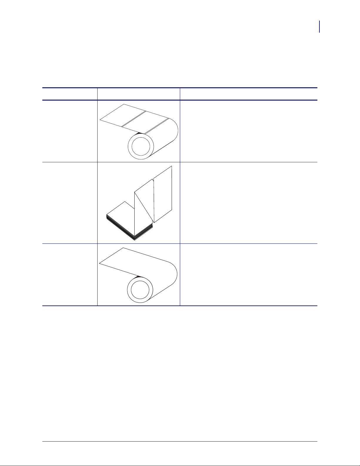
Table 1 • Types of Media
Media Type How It Looks Description
Types of Media
4
Non-Continuous
Roll Media
Non-Continuous
Fanfold Media
Continuous
Roll Media
Roll media is wound on a 3-in. (76-mm) core. Labels
have adhesive backing that sticks them to a liner, and
they are separated by gaps, holes, notches, or black
marks. Tags are separated by perforations.
Fanfold media is folded in a zigzag pattern. Fanfold
media can have the same label divisions as noncontinuous roll media. The divisions would fall on or
near the folds.
Continuous media is wound on a core and is without
gaps, holes, notches, or black marks. This allows the
image to be printed anywhere on the label. With
continuous media, use the transmissive sensor so the
printer can detect when the media runs out.
12/6/06 MVPplus Quick Reference Guide 14069L-001 Rev. A
Page 5

Load Media
5
Load Media
Use the instructions in this section to load roll media in Tear-Off mode (Figure 3). For
instructions for loading fanfold media or for loading in different print modes, refer to the
User Guide.
Figure 3 • Tear-Off Mode Media Path
Caution • When you are loading media or ribbon, remove all jewelry that could come into
contact with the printhead or other printer parts.
To Load Roll Media in Tear-Off Mode, complete these steps:
1. Remove and discard any tags or labels that are dirty or that are held by adhesives or tape.
Tag Stock Labels
2. Place the roll of media on the media supply spindle. Push the roll as far back as it will go.
14069L-001 Rev. A MVPplus Quick Reference Guide 12/6/06
Page 6

Load Media
123
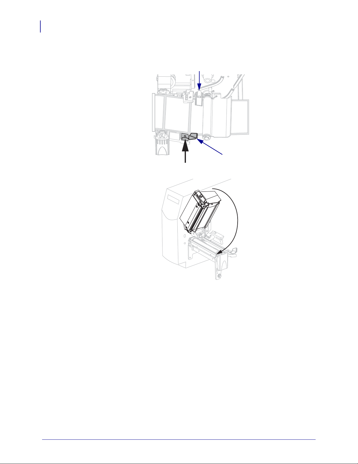
3. Press the printhead release latch to open the printhead assembly. Lift the printhead until it
latches open.
4. Slide out the media guide.
6
5. Feed the media under the dancer assembly (1), through the slot in the transmissive
sensor (
2—standard transmissive sensor shown), and under the ribbon sensor (3).
12/6/06 MVPplus Quick Reference Guide 14069L-001 Rev. A
Page 7
Load Media
7
6. Push the media to the back of the transmissive sensor (1). Slide in the media guide (2)
until it touches the edge of the media.
1
2
7. Close the printhead assembly.
8. If the printer is paused (the Pause light is blinking), press PAUSE to enable printing.
14069L-001 Rev. A MVPplus Quick Reference Guide 12/6/06
Page 8
Position the Media Sensors
1
This printer uses two types of media sensors: transmissive and reflective.
Select or Position the Transmissive Sensor
By default, the printer uses the transmissive sensor (Figure 4), which you can adjust for
optimal print performance. The reflective sensor is a secondary media sensing system that is
activated only if the transmissive sensor cannot be used to calibrate the media.
Figure 4 • Adjustable Transmissive Sensor
Position the Media Sensors
8
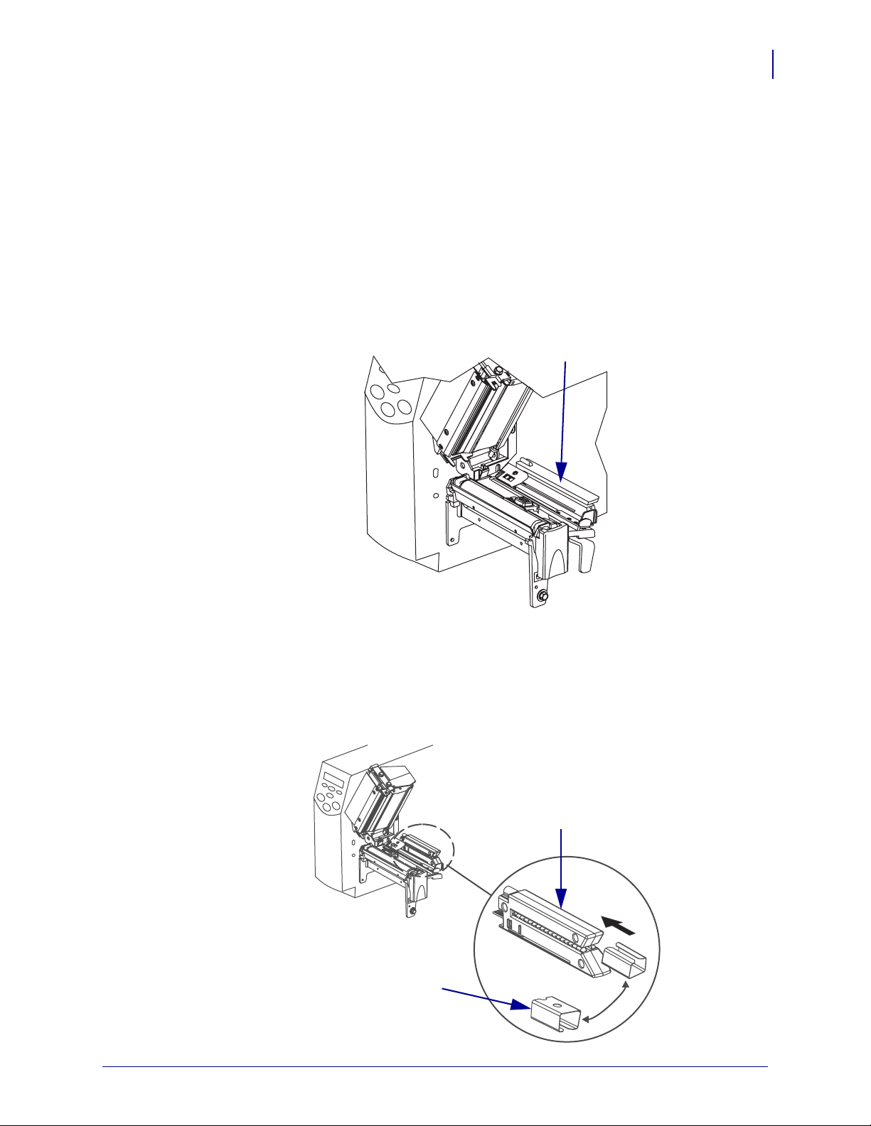
The transmissive sensor is equipped with a slide-on sensor sleeve (Figure 5). This sleeve has a
notch on one end and a hole in the middle, which help the printer calibrate media that has an
edge notch or an intra-label gap.
Figure 5 • Adjustable Transmissive Sensor and Sensor Sleeve
1
2
12/6/06 MVPplus Quick Reference Guide 14069L-001 Rev. A
Page 9

Position the Media Sensors
9
The positioning marks correspond to the notch and hole in the sensor sleeve.
Figure 6 • Transmissive Sensor with Adjustment Tab Pointer
1
3
Sensor sleeve
1
Positioning marks
2
Adjustment tab pointer (outer position)
3
Adjustment tab pointer (inner position)
4
To adjust the transmissive sensor, complete these steps:
1. Press the printhead open lever to release the printhead assembly.
2. See Figure 4. Locate the transmissive sensor.
3. Push the sensor sleeve all the way in on the transmissive sensor.
1
2
4
2
4. Locate the white adjustment tab pointer on the back of the transmissive sensor.
5. What type of media are you using?
If you are using… Then…
Non-continuous media
with notched edges
Non-continuous media
without notched edges
Move the adjustment tab pointer to the inner positioning
mark. The point of the tab should align with the mark.
Move the adjustment tab to the outer positioning mark. The
point of the tab should align with the mark.
Continuous media Move the adjustment tab to the outer positioning mark. The
point of the tab should align with the mark.
Note • Certain types of media may require you to position the adjustment tab to locations
outside of the sensor sleeve.
6. Ensure the media and ribbon are properly positioned.
7. Close the printhead assembly.
14069L-001 Rev. A MVPplus Quick Reference Guide 12/6/06
Page 10

Adjust the Reflective Sensor
Note • This sensor is typically covered by a factory-installed plate. If you need to enable this
sensor, you must remove the plate.
The reflective sensor is compatible with most types of media. With non-continuous media, the
reflective sensor detects the start-of-label indicator (the notch, hole, black mark, or gap
between die-cut labels). With both continuous media and non-continuous media, the sensor
detects an out-of-paper condition.
Position the reflective sensor in the following way:
• directly under the notch, hole, or black mark with these types of labels
• anywhere along the width of the media if there is a gap between labels
• anywhere under the media for continuous media
The glow of the red light through the media may help you accurately position the sensor.
Figure 7 • Adjusting the Reflective Sensor
Position the Media Sensors
10
4
Printhead assembly
1
Reflective sensor
2
Reflective sensor positioning lever
3
Printhead release latch
4
1
2
3
12/6/06 MVPplus Quick Reference Guide 14069L-001 Rev. A
Page 11

Position the Media Sensors
11
To adjust the reflective sensor, complete these steps:
1. See Figure 7. Press the printhead release latch.
2. Lift the printhead until it latches open.
3. Locate the reflective sensor positioning lever.
4. Move the reflective sensor positioning lever across the width of the media until the
reflective sensor aligns with the gap or notch.
5. Close the printhead assembly.
14069L-001 Rev. A MVPplus Quick Reference Guide 12/6/06
Page 12

Ribbon Overview
Ribbon is a thin film that is coated on one side with wax, resin, or wax resin, which is
transferred to the media during the thermal transfer process.
When to Use Ribbon
Thermal transfer media requires ribbon for printing while direct thermal media does not.
To determine if ribbon must be used with a particular media, perform a media scratch test.
To perform a media scratch test, complete these steps:
1. Scratch the print surface of the media rapidly with your fingernail.
2. Did a black mark appear on the media?
If a black mark... Then the media is...
Does not appear on the media Thermal transfer. A ribbon is required.
Appears on the media Direct thermal. No ribbon is required.
Ribbon Overview
12
Coated Side of Ribbon
Ribbon can be wound with the coated side on the inside or outside (Figure 8). This printer can
only use ribbon that is coated on the outside.
Figure 8 • Ribbon Coated on Outside or Inside
To determine which side of a ribbon is coated, complete these steps:
1. Peel a label from its liner.
2. Press a corner of the sticky side of the label to the outer surface of the roll of ribbon.
3. Peel the label off of the ribbon.
Outside Inside
12/6/06 MVPplus Quick Reference Guide 14069L-001 Rev. A
Page 13

Ribbon Overview
13
4. Observe the results. Did flakes or particles of ink from the ribbon adhere to the label?
If ink from the ribbon... Then...
Adhered to the label The ribbon is coated on the outer surface.
Did not adhere to the label The ribbon is coated on the inner surface and cannot be
used in this printer. To verify this, repeat the test on the
other surface of the roll of ribbon.
14069L-001 Rev. A MVPplus Quick Reference Guide 12/6/06
Page 14

Load Ribbon
Always use ribbon that is wider than the media to protect the printhead from wear. For direct
thermal printing, do not load ribbon in the printer.
Figure 9 • Ribbon Path
Load Ribbon
14
3
2
1
Printhead assembly
1
Ribbon supply spindle
2
Ribbon take-up spindle
3
Tension blades
4
4
12/6/06 MVPplus Quick Reference Guide 14069L-001 Rev. A
Page 15

15
Load Ribbon
Caution • When you are loading media or ribbon, remove all jewelry that could come into
contact with the printhead or other printer parts.
To load ribbon, complete these steps:
1. Press the printhead release latch to open the printhead assembly. Lift the printhead until it
latches open.
2. Orient the ribbon with the loose end unrolling clockwise.
3. Place the roll of ribbon on the ribbon supply spindle (1) and push it all the way back.
1
14069L-001 Rev. A MVPplus Quick Reference Guide 12/6/06
Page 16

Load Ribbon
4. Pull the end of the ribbon under the printhead assembly (1) and out the front of the printer.
1
5. Close the printhead assembly.
16
6. Wind the ribbon clockwise onto the ribbon take-up spindle (1).
1
12/6/06 MVPplus Quick Reference Guide 14069L-001 Rev. A
Page 17

17
Load Ribbon
Remove Used Ribbon
To remove used ribbon, complete these steps:
1.
Caution • Do not cut the ribbon directly on the ribbon take-up spindle. Doing so may
damage the spindle.
If the ribbon has not run out, cut or break it before the ribbon take-up spindle (1).
1
2.
To loosen the ribbon, squeeze it against the ribbon take-up spindle tension blades (1). At
the same time, turn the ribbon take-up spindle release knob counterclockwise (
2).
The tension blades collapse into the ribbon take-up spindle, loosening the ribbon.
1
2
3. Slide the used ribbon off of the ribbon take-up spindle and discard.
14069L-001 Rev. A MVPplus Quick Reference Guide 12/6/06
Page 18

Adjust Printhead Pressure
You may need to adjust printhead pressure if printing is too light on one side or if you use thick
media.
See Figure 10. The pressure adjustment dials have different settings that are designated by
blocks of increasing size embossed on the print mechanism. The smallest block (fully
counterclockwise) is considered position 1, and the largest block (fully clockwise) is
considered position 4 (or 7 for the 300MVPplus).
Figure 10 • Printhead Pressure Adjustment Dials
Adjust Printhead Pressure
18
1
1
2
2
Outside dial
Inside dial
To set printhead pressure, complete these steps:
1. Use Table 2 or Tab le 3 to select the initial dial settings for your media, depending on
which printer you have.
Table 2 • 200MVPplus Printhead Pressure
Media Width
1 in. (25.4 mm)
2 in. (51 mm)
3 in. (76 mm)
3.5 in. and up (89 mm and up)
12/6/06 MVPplus Quick Reference Guide 14069L-001 Rev. A
Inside Dial Outside Dial
31
41
32
33
Page 19

Adjust Printhead Pressure
19
Table 3 • 300MVPplus Printhead Pressure
Media Width
Inside Dial Outside Dial
2 in. (50 mm) 6 1
3 in. (75 mm) 6 2
4 in. (100 mm) 7 3
5 in. (125 mm) 7 4
5.5 in. and up (140 mm and up) 6 6
2. If necessary, adjust the pressure adjustment dials as follows:
If the media... Then...
Requires higher pressure to
Increase both dials one position.
print well
Shifts left while printing Increase the outside dial setting one position, or
decrease the inside dial setting one position.
Shifts right while printing Increase the inside dial setting one position, or
decrease the outside dial setting one position.
Prints too lightly on the left side
Increase the inside dial setting one position.
of the label.
Prints too lightly on the right
side of the label.
Increase the outside dial setting one position.
14069L-001 Rev. A MVPplus Quick Reference Guide 12/6/06
Page 20

Control Panel
PAUSE
The control panel (Figure 11) contains the lights that reflect basic operation and the buttons
that you may need to press during basic operation.
Control Panel
20
Figure 11 • Control Panel
1 2 3 4
5
6
Power light Indicates that the printer is on.
1
PAUSE light Blinks when the printer is paused.
2
Error light Blinks or remains on when the
3
printer needs attention.
Data light Blinks quickly when the printer is
4
receiving data.
LCD Shows the printer’s operating
5
status.
PAUSE button Starts or stops printer operation
6
when pressed.
12/6/06 MVPplus Quick Reference Guide 14069L-001 Rev. A
Page 21

Print a Configuration Label
21
Print a Configuration Label
A configuration label lists the printer settings that are stored in configuration memory. After
you load the media and ribbon (if necessary), print a configuration label as a record of your
printer’s current settings. Keep the label to use when troubleshooting printing problems.
To print a configuration label, complete these steps:
1. On the control panel, press SETUP/EXIT.
2. Press PLUS (+) or MINUS (-) to scroll through the parameters until you reach
LIST SETUP.
3. Press SELECT to select the parameter.
4. Press PLUS (+) to confirm printing.
A configuration label prints (Figure 12).
Figure 12 • Configuration Label
14069L-001 Rev. A MVPplus Quick Reference Guide 12/6/06
Page 22

Configure the Printer
Use the LCD on the control panel to view and adjust printer settings.
Note • Your label preparation software or the printer driver may override adjustments made
through the control panel. Refer to the software or driver documentation for more
information.
How to View or Modify Parameters
To view or modify parameters, complete these steps:
1. Press SETUP/EXIT to enter Setup mode.
2. While viewing parameters, press PLUS (+) to continue to the next parameter, or press
MINUS (-) to return to the previous parameter in the cycle.
3. Press SELECT when you wish to modify a parameter or view its options.
4. Press or to modify the parameter.
When a parameter is changed, an asterisk (*) appears in the upper left corner of the display
to indicate that the value is different from the one currently active in the printer.
Configure the Printer
22
5. Press SETUP/EXIT.
The LCD displays
6. Press to display the save options (Table 4).
LCD Description
PERMANENT
TEMPORARY
CANCEL
LOAD DEFAULTS
LOAD LAST SAVE
DEFAULT NET
SAVE CHANGES.
Table 4 • Save Options When Leaving Setup Mode
Stores values in the printer even when power is turned off.
Saves the changes until power is turned off.
Cancels all changes made since you entered Setup mode,
except for changes made to the darkness and tear-off settings,
which go into effect as soon as they are made.
Restores all parameters other than the network settings back to
the factory defaults. Use care when loading defaults because
you will need to reload all settings that you changed manually.
Note • Loading factory defaults causes the printer to
auto-calibrate.
Loads values from the last permanent save.
Restores the wired and wireless network settings back to
factory defaults.
7. Press SETUP/EXIT to select the displayed choice.
When the configuration and calibration sequence is done,
12/6/06 MVPplus Quick Reference Guide 14069L-001 Rev. A
PRINTER READY displays.
Page 23

Configure the Printer
23
Basic Printer Parameters
Table 5 shows some parameters that you may need to change to configure your printer
initially. Refer to the User Guide for the complete list of printer parameters.
Menu Display Description
Table 5 • Printer Parameters
DARKNESS
PRINT MODE
MEDIA TYPE
SENSOR TYPE
SENSOR SELECT
PRINT METHOD
Adjust Print Darkness
Default: +10
Range: 0 to 30
Select Print Mode
Default: TEAR-OFF
Selections: TEAR-OFF, PEEL-OFF, CUTTER, REWIND
Set Media Type
See Types of Media on page 4 for more information about media types.
Default: NON-CONTINUOUS
Selections: CONTINUOUS, NON-CONTINUOUS
Set the Sensor Type
Default: WEB
Selections: WEB (gaps or perforations between labels), MARK (black marks on
the back of the liner to indicate where labels end)
Select a Sensor
Default: TRANSMISSIVE
Selections: AUTO SELECT (the printer uses what it thinks is the best sensor),
REFLECTIVE (black mark media), TRANSMISSIVE (most other media types)
Select Print Method
Default: THERMAL TRANSFER
Selections: THERMAL TRANSFER (uses ribbon), DIRECT THERMAL
(does not use ribbon)
14069L-001 Rev. A MVPplus Quick Reference Guide 12/6/06
Page 24

Cleaning Procedures
Cleaning Procedures
Important • Brady is not responsible for damage caused by the use of cleaning fluids on this
printer.
Specific cleaning procedures are provided on the following pages. shows the recommended
cleaning schedule. These intervals are intended as guidelines only. You may have to clean
more often, depending upon your application and media.
Table 6 • Recommended Cleaning Schedule
Area Method Interval
Printhead Solvent* Direct Thermal Mode: After every roll of
Platen roller Solvent*
Media sensors Air blow
media (or 500 feet of fanfold media).
Thermal Transfer Mode: After every roll of
ribbon or three rolls of media.
Ribbon sensor Air blow
Media path Solvent*
.
24
Ribbon path Solvent*
Pinch roller. (part of Peel-Off option) Solvent*
Cutter
module
If cutting continuous,
pressure-sensitive media
If cutting tag stock or label
liner material
Solvent* After every roll of media (or more often,
depending upon your application and media).
Solvent* and
After every two or three rolls of media.
air blow
Tear-off/peel-off bar Solvent* Once a month.
Take-label sensor Air blow Once every six months.
* Brady recommends using Preventive Maintenance Kit (part number PCK-4). In place of this kit, you may use a clean swab
dipped in a solution of isopropyl alcohol (minimum 90%) and deionized water (maximum 10%).
Clean the Exterior
You may clean the exterior surfaces of the printer with a lint-free cloth and a small amount of a
mild detergent, if necessary. Do not use harsh or abrasive cleaning agents or solvents.
12/6/06 MVPplus Quick Reference Guide 14069L-001 Rev. A
Page 25

Cleaning Procedures
25
Clean the Printhead and Platen Roller
You can minimize printhead wear and maintain print quality with regular preventive measures.
To avoid abrasion:
• Clean the printhead frequently, and use well-lubricated thermal transfer ribbons with
backings optimized to reduce friction.
• Minimize printhead pressure and burn temperature settings by optimizing the balance
between the two.
• Ensure that the thermal transfer ribbon is as wide or wider than the label media to prevent
exposing the elements to the more abrasive label material.
For best results, clean the printhead after changing every roll of ribbon. Inconsistent print
quality, such as voids in the bar code or graphics, may indicate a dirty printhead.
-
Note • For printers with a peel assembly, keep the peel assembly closed while cleaning the
platen roller to reduce the risk of bending the tear-off/peel-off bar.
Figure 13 • Location of the Printhead and Platen Roller
2
Printhead assembly
1
Platen roller
2
1
14069L-001 Rev. A MVPplus Quick Reference Guide 12/6/06
Page 26

Cleaning Procedures
Caution • The printhead may be hot and could cause severe burns. Allow the printhead
to cool.
Caution • Before touching the printhead assembly, discharge any built-up static electricity
by touching the metal printer frame or by using an anti-static wriststrap and mat.
To clean the printhead and platen roller, complete these steps:
1. Open the printhead assembly.
2. Remove the media and ribbon.
3. Using the swab from the Preventive Maintenance Kit (part number PCK-4), wipe along
the brown strip on the printhead assembly from end to end. In place of the Preventive
Maintenance Kit, you may use a clean swab dipped in a solution of isopropyl alcohol
(minimum 90%) and deionized water (maximum 10%). Allow the solvent to evaporate.
26
4. While manually rotating the platen roller, clean it thoroughly with the swab. Allow the
solvent to evaporate.
12/6/06 MVPplus Quick Reference Guide 14069L-001 Rev. A
Page 27

Cleaning Procedures
27
5. Reload media and ribbon, and close the printhead assembly.
Note • If performing this procedure does not improve print quality, try cleaning the
printhead with Save-A-Printhead cleaning film. This specially coated material removes
contamination buildup without damaging the printhead. Call your authorized Brady
reseller for more information.
14069L-001 Rev. A MVPplus Quick Reference Guide 12/6/06
Page 28

Fuse Replacement
A user-replaceable AC power fuse is located just below the AC power switch at the rear of the
printer. The replacement fuse is a 5 × 20 mm fast-blow style rated at 5 Amp/250 VAC.
Caution • Turn off (O) the printer and disconnect it from the power source before
performing the following maintenance.
2
1
Fuse Replacement
28
Figure 14 • Replacing the Fuse
4
3
Slot
1
Fuse holder
2
Fuse
3
Fuse socket
4
To replace the fuse, complete these steps:
1. See Figure 14. Insert the tip of a flat blade screwdriver into the slot in the end of the fuse
holder.
2. Turn the screwdriver counterclockwise until the fuse holder disengages from fuse socket.
3. Remove the fuse holder from the fuse socket.
4. Remove the old fuse from the fuse holder.
5. Insert a new, compatible fuse into the fuse holder.
6. Place the fuse holder into the fuse socket.
7. Insert the tip of a flat blade screwdriver into the slot in the end of the fuse holder.
8. With the screwdriver, press in gently, and then turn the screwdriver clockwise until the
fuse holder engages.
12/6/06 MVPplus Quick Reference Guide 14069L-001 Rev. A
 Loading...