

Page 1
05/01
instructions
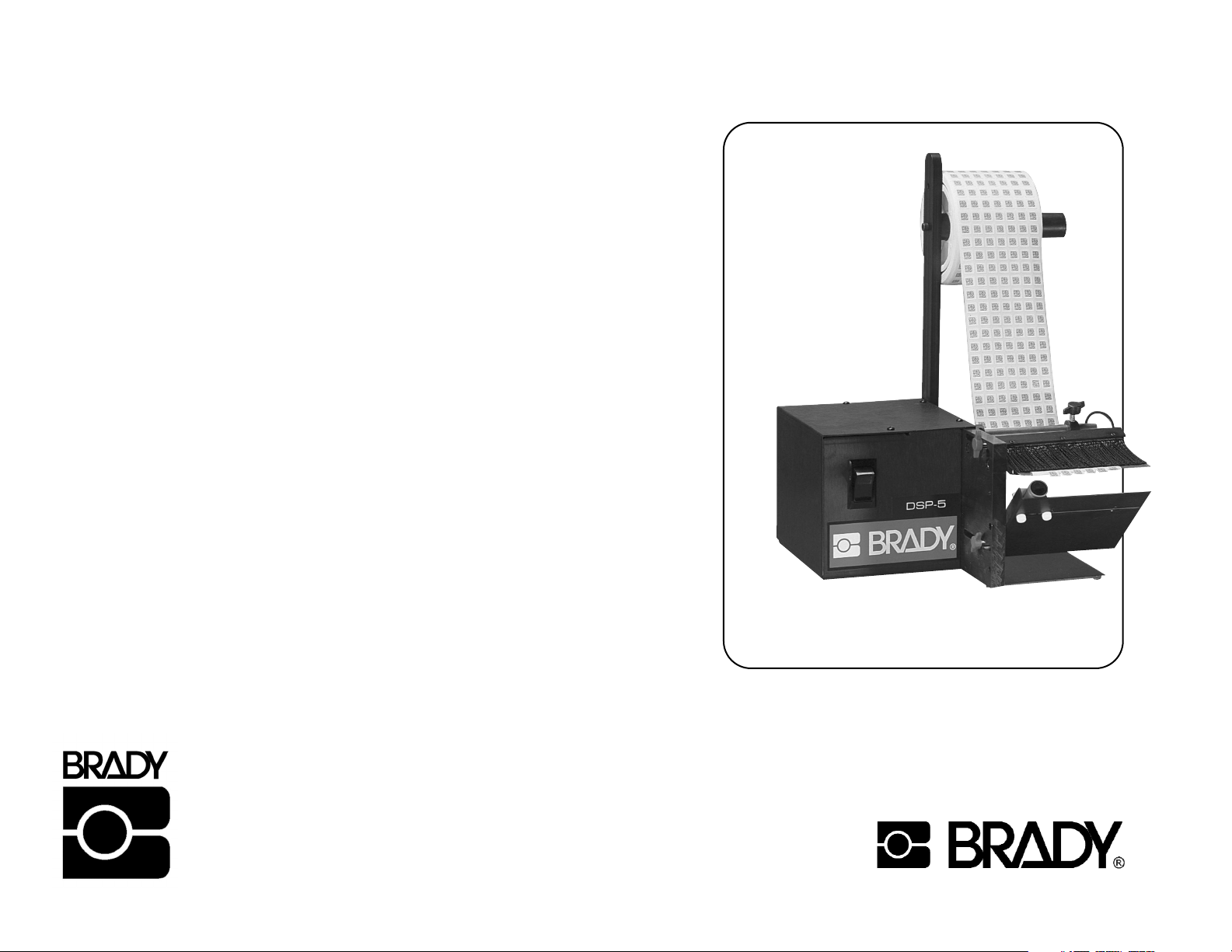
DSP-5
Brady Worldwide Identification Solutions
6555 West Good Hope Road
P.O. Box 2131
Milwaukee, WI 53201-2131
Phone: (800) 537-8791
Fax: (800) 292-2289
www.bradyid.com
Page 2
7
2
CONTENTS
Read this user’s manual before use to ensure proper operation. Keep the manual on
hand for reference in case there is a problem.
Warranty Information .....................2
Features .........................................3
Notes ............................................3
Repair Policy ..................................3
Specifications .................................3
Set-up ............................................4
Operation/Adjustments ...................5
Maintenance ..................................6
Legend ...........................................6
Exploded View ...............................7
Brady Corporation warrants all parts on DSP series label dispensers against defects
in design, materials and workmanship for a period of 180 days. Labor to replace
defective parts will be performed at no charge for the first 90 days after date of
purchase. Warranty does not cover transportation costs.
Our sole obligation under this warranty is limited to repair, replacement or credit of
the purchase price, at our option, for the machines listed above, which do not
perform properly the function for which they were designed.
Warranty repair is contingent upon our examination and determination that alleged
defects have not been caused by misuse, abuse, improper installation or application,
repair, alteration, accident or neglect in use, storage, transportation or handling.
The above warranty and remedy constitutes Brady Corporation’s sole liability
hereunder and are in lieu and exclusive of all other warranties and remedies
expressed, implied, or statutory, including, but not limited to, those of merchantability
and fitness for a particular purpose.
WARRANTY POLICY FOR DSP SERIES LABEL DISPENSERS
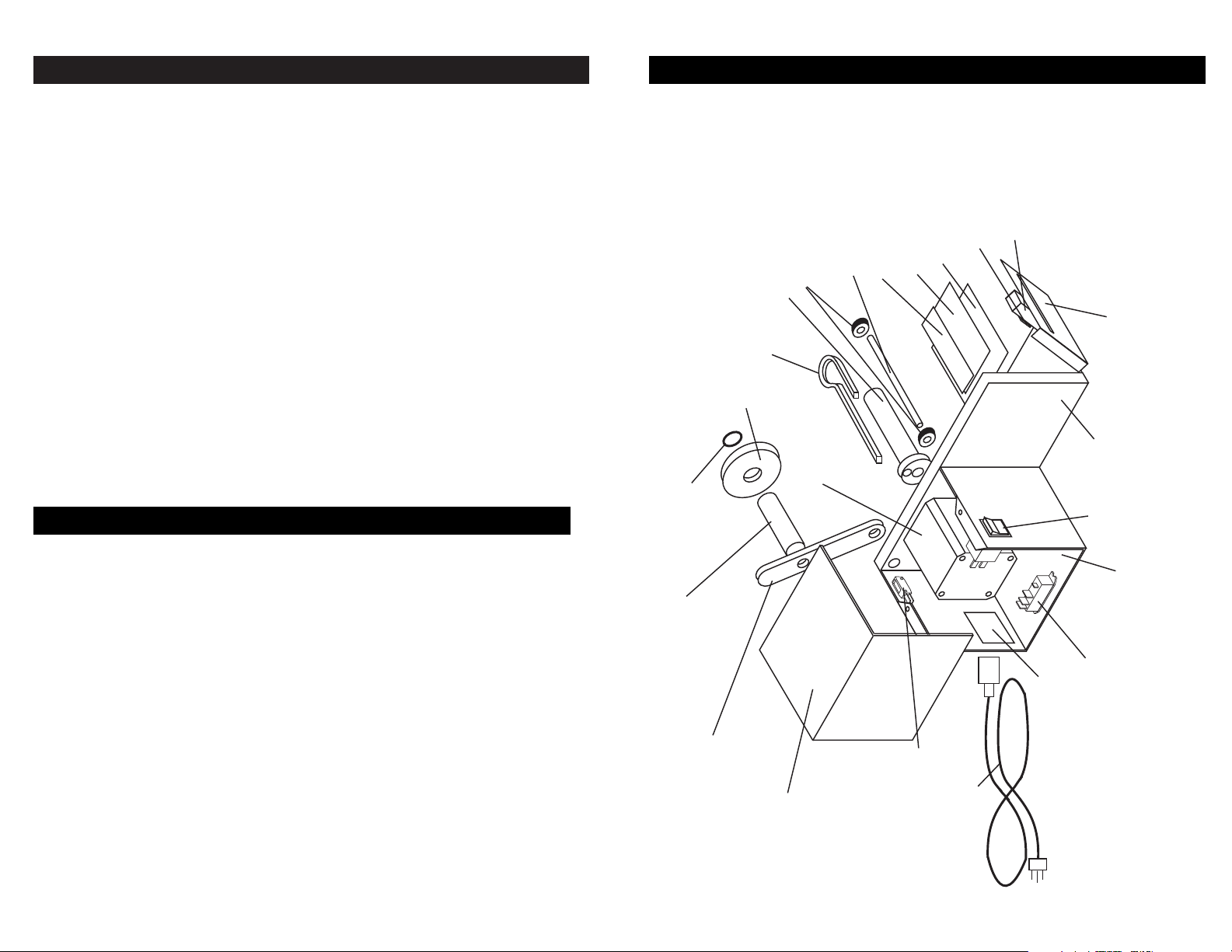
EXPLODED VIEW
9-SHAFT COLLAR
8A-Hub/Motor set screw(1ea)
8-TAKEUP HUB
10-GUIDE ROD
10A-Rod/Main Plate screw(1ea)
9A-"T" adjustment screw(1ea)
12-HOLD DOWN BRUSH
11-BRUSH HOLDER
11A-Holder/Main Plate "T" screw(1ea)
11B-Holder/Brush set screw(3ea)
15-PHOTOSENSOR
(For clear or reflective material,
consult factory.)
14-NUTPLATE FOR BRACKET
13A-Strip Plate/Main Plate screw(2ea)
13B-Teflon tape
13-STRIP PLATE
5-3" SPOOL (2 each)
4-O RING
3-REEL HANGER BAR
3A-Bar/Arm screw(1ea)
2-REEL HOLDER ARM
2A-Arm/Main Plate screw(1ea)
2B-Hex wrench
7-SQUARE LOCK ROD
6-MOTOR
6A-Motor/Main Plate screw(4ea)
6B-Grounding nut(1ea)
23-SAFETY SWITCH
22-POWER CORD
23A-Switch/Base screw(2ea)
23B-Nut(2ea)
16-PHOTOSENSOR BRACKET
17-MAIN PLATE
18-POWER SWITCH
20-RELAY
20A-Relay/Base screw(2ea)
21-POWER INLET
21A-Fuse(1ea)
20B-Nut(2ea)
16A-Bracket/Main Plate "T" screw(1ea)
16B-Bracket/Sensor thumbscrew(2ea)
19-BASE
19A-Base/Main Plate screw(2ea)
NOTE: Drawing not to scale – for reference only.
1-COVER
1A-Cover/Base screw (4ea)
1B-Cover/Main Plate screw(2ea)
Page 3

5
4
Using 5/32" (4mm) hex wrench, adjust reel holder arm to vertical.
Place the label roll on the 1" (25mm) reel hanger bar.
*If roll has 3" (76.2mm) core, use plastic spool*
Slide “O” ring onto reel hanger bar to hold roll against reel holder arm to ensure it is
held straight.
(Hex wrench, O-ring and spool included.)
Thread the liner under the guide rod, between the hold down brush and the strip plate,
then back under the strip plate. Lay the liner across the slot in the take-up hub. Slide the
lock rod into the slot to secure the liner. Align shaft collar on guide rod with edge of
liner to keep material feeding straight.
Hold Down Brush:
Using the upper thumbscrew on the side of the machine, adjust the hold down brush for
tensioning.
For best results, labels should be pressed firmly against the strip plate. If labels are held
too tightly, they will cause excessive drag on the motor.
Photosensor:
The photosensor can be adjusted in any direction to accommodate virtually any label.
Loosening the lower thumbscrew allows the photosensor to swivel and sets the overhang
distance of the label over the strip plate. When the label is being fed the correct
distance, tighten the lower thumbscrew.
Loosen the two screws on the front of the sensor holder to align the photosensor with
the center of the label. If there are two or more labels across, align the photosensor
with the last label to be removed. When these two screws are tightened, the machine
is set.
Hold Down Brush
Photosensor
Strip Plate
Guide Rod
Lock Rod
Take-up Hub
Reel Hanger Bar
Reel Holder Arm
Incorrect
Correct
Sensor sees beyond label
- Will not stop
Sensor sees strip plate
- Will not feed
Sensor sees front edge of label
ADJUSTMENTS
SET-UP INSTRUCTIONS
Positioning of Photosensor
Page 4

6
3
MAINTENANCE
Turn machine off when not in use. Remove liner material from take-up hub at
approximately 3" in diameter or if motor appears to be straining. Do not operate
machine without covers in place. Do not operate if inspection reveals a damaged
power or sensor cord.
• Will dispense butt-cut and die-cut material.
• Adjustable photosensor for pinpoint accuracy.
• Handled lock rod makes scrap removal easy.
• No tools required for adjustment.
• Keep strip plate free of adhesive build-up.
• Clean photosensor with compressed air or dry cloth.
• Do not drop the dispenser or subject it to heavy shock.
• Turn off machine when not in use.
Contact BRADY CORPORATION to determine nature of problem.
Furnish Brady with the following information:
1. Who the unit was purchased from.
2. Model number and serial number.
3. Date purchased (copy of invoice or packing slip required).
Brady will issue an RGA (Return Goods Authorization) for repair.
Return machine to Brady by UPS, insured and prepaid.
Brady will notify the customer if there is a repair charge.
FEATURES
NOTES
REPAIR POLICY
Model# DSP-5
Liner Capacity .25" to 4.5"
Width (6.35mm to 115mm)
Label .125" to 7"
Length (3.2mm to 178mm)
Roll Capacity 12" (30.5mm)
Feed Speed 1.3" / sec*
(3.3mm / sec.)
Dimensions
Inches 10.8 (L) x 10.8 (W) x 14.5 (H)
Centimeters 27.4 (L) x 27.4 (W) x 36.8 (H)
Weight 10.5 lb. (4.76 kg.)
Electrical 117V 50/60Hz, <1 amp
Requirements (220V 50/60Hz available)
SPECIFICATIONS:
*at start-up
LEGEND
Model DSP-5
Item # Part #
1 NV50008
1A NV50008-1
1B NV50008-2
2 NV50010
2A NV50010-1
2B NV50010-2
3 NV50017
3A NV50017-1
4 NV50017-2
5 NV-SPOOL
6 NV50001A (115V)
NV50001C (220V)
6A NV50001-1
6B NV50018-2
7 NV50013A
8 NV50012
8A NV50012-1
9 NV50014-1
9A NV50014-3
10 NV50014
10A NV50017-1
11 NV50026B
11A NV50011-2
11B NV50026-1
12 NV50026A
13 NV50015
13A NV50017-1
13B NV50015A
14 NV50011A
15 NV50002A
16 NV50011
16A NV50011-2
16B NV50011-1
17 NV50007
18 NV50003
19 NV50009
19A NV50007-1
20 NV50021 (115V)
NV50021A (220V)
20A NV50005-1
20B NV50021-1
21 NV50019
21A NV50019F
22 NV50018C
23 NV50005
23A NV50005-1
23B NV50021-1
 Loading...