

Brady BradyPrinter 300X-Plus II, BradyPrinter 600X-Plus II, BradyPrinter 360X-Plus II User Manual
Page 1

Br adyprinter
300X-Plus II
360X-Plus II
600X-Plus II
™
THT
Page 2

© 2004 Brady Worldwide Inc.
This copyrighted guide and the label printers described herein are licensed to
Brady Corporation. All rights are reserved. Unauthorized reproduction of the
guide or the software in the label printer may result in imprisonment of up to
one year and fines of up to $10,000 (17 U.S.C.506). Copyright violators may
be subject to civil liability.
IBM® is a registered trademark of IBM Corporation.
Adobe® and Acrobat® are registered trademarks of Adobe Systems
Incorporated.
BradyPrinter™ is a trademark of Brady Corporation. BradyConnect® is a
registered trademark of Brady Corporation.
ZPL® and ZPL II® are registered trademarks of Zebra Technologies.
All other brand names, product names, or trademarks belong to their respective
holders.
Document Name: 13383L-12r1.pdf
Page 3

Table of Contents
Proprietary Statement. . . . . . . . . . . . . . . . . . . . . . . . . . . . . . . . . . . . . . v
Product Improvements. . . . . . . . . . . . . . . . . . . . . . . . . . . . . . . . . . . . . . . . . . v
FCC Compliance Statement . . . . . . . . . . . . . . . . . . . . . . . . . . . . . . . . . . . . . v
Canadian DOC Compliance Statement . . . . . . . . . . . . . . . . . . . . . . . . . . . . vi
Liability Disclaimer . . . . . . . . . . . . . . . . . . . . . . . . . . . . . . . . . . . . . . . . . . . . . vi
Limitation of Liability. . . . . . . . . . . . . . . . . . . . . . . . . . . . . . . . . . . . . . . . . . . . vi
Warranty Information . . . . . . . . . . . . . . . . . . . . . . . . . . . . . . . . . . . . . .ix
Printers and Related Hardware Products. . . . . . . . . . . . . . . . . . . . . . . . . . . . ix
Supplies Products . . . . . . . . . . . . . . . . . . . . . . . . . . . . . . . . . . . . . . . . . . . . . xi
Repair Services . . . . . . . . . . . . . . . . . . . . . . . . . . . . . . . . . . . . . . . . . . . . . . . xi
Warranty Exclusions & Conditions Statement . . . . . . . . . . . . . . . . . . . . . . . . xi
Printer Software and Firmware License Agreement . . . . . . . . . . . .xiii
Preface . . . . . . . . . . . . . . . . . . . . . . . . . . . . . . . . . . . . . . . . . . . . . . . . .xix
Contacts . . . . . . . . . . . . . . . . . . . . . . . . . . . . . . . . . . . . . . . . . . . . . . . . . . . . . . xx
Support . . . . . . . . . . . . . . . . . . . . . . . . . . . . . . . . . . . . . . . . . . . . . . . . . . . . xx
About this Document . . . . . . . . . . . . . . . . . . . . . . . . . . . . . . . . . . . . . . . . . . . . . xxi
Document Conventions . . . . . . . . . . . . . . . . . . . . . . . . . . . . . . . . . . . . . . . . . . .xxii
Related Documents. . . . . . . . . . . . . . . . . . . . . . . . . . . . . . . . . . . . . . . . . . . . . .xxv
Bradyprinter THT X-Plus II Series User Guide i
Page 4

Table of Contents
1 • Chapter 1 • Introduction1
Exterior View . . . . . . . . . . . . . . . . . . . . . . . . . . . . . . . . . . . . . . . . . . . . . . . . . . . . 2
Front Panel . . . . . . . . . . . . . . . . . . . . . . . . . . . . . . . . . . . . . . . . . . . . . . . . . . . . . 3
Front Panel Buttons . . . . . . . . . . . . . . . . . . . . . . . . . . . . . . . . . . . . . . . . . . . . 4
Front Panel Lights . . . . . . . . . . . . . . . . . . . . . . . . . . . . . . . . . . . . . . . . . . . . . 5
Printer Components . . . . . . . . . . . . . . . . . . . . . . . . . . . . . . . . . . . . . . . . . . . . . . 6
2 • Chapter 2 • Getting Started9
Before You Begin. . . . . . . . . . . . . . . . . . . . . . . . . . . . . . . . . . . . . . . . . . . . . . . . 10
Unpack and Inspect the Printer . . . . . . . . . . . . . . . . . . . . . . . . . . . . . . . . . . . . . 11
Report Shipping Damage. . . . . . . . . . . . . . . . . . . . . . . . . . . . . . . . . . . . . . . 11
Store or Reship the Printer. . . . . . . . . . . . . . . . . . . . . . . . . . . . . . . . . . . . . . 11
Select a Site for the Printer . . . . . . . . . . . . . . . . . . . . . . . . . . . . . . . . . . . . . . . . 12
Select a Surface. . . . . . . . . . . . . . . . . . . . . . . . . . . . . . . . . . . . . . . . . . . . . . 12
Provide Proper Operating Conditions . . . . . . . . . . . . . . . . . . . . . . . . . . . . . 12
Allow Proper Space . . . . . . . . . . . . . . . . . . . . . . . . . . . . . . . . . . . . . . . . . . . 12
Provide a Data Source. . . . . . . . . . . . . . . . . . . . . . . . . . . . . . . . . . . . . . . . . 12
Connect the Printer to a Power Source. . . . . . . . . . . . . . . . . . . . . . . . . . . . . . . 13
Power Cord . . . . . . . . . . . . . . . . . . . . . . . . . . . . . . . . . . . . . . . . . . . . . . . . . 13
Communication Interfaces. . . . . . . . . . . . . . . . . . . . . . . . . . . . . . . . . . . . . . . . . 15
Data Cable Requirements . . . . . . . . . . . . . . . . . . . . . . . . . . . . . . . . . . . . . . 16
Types of Media . . . . . . . . . . . . . . . . . . . . . . . . . . . . . . . . . . . . . . . . . . . . . . . . . 17
Continuous Media . . . . . . . . . . . . . . . . . . . . . . . . . . . . . . . . . . . . . . . . . . . . 17
Non-Continuous Black Mark Media . . . . . . . . . . . . . . . . . . . . . . . . . . . . . . . 17
Non-Continuous Web Media . . . . . . . . . . . . . . . . . . . . . . . . . . . . . . . . . . . . 18
Ribbon . . . . . . . . . . . . . . . . . . . . . . . . . . . . . . . . . . . . . . . . . . . . . . . . . . . . . . . . 19
3 • Chapter 3 • Printer Operation21
Load the Printer. . . . . . . . . . . . . . . . . . . . . . . . . . . . . . . . . . . . . . . . . . . . . . . . . 22
Load Roll Media . . . . . . . . . . . . . . . . . . . . . . . . . . . . . . . . . . . . . . . . . . . . . . 22
Load Fanfold Media . . . . . . . . . . . . . . . . . . . . . . . . . . . . . . . . . . . . . . . . . . . 24
Load Ribbon. . . . . . . . . . . . . . . . . . . . . . . . . . . . . . . . . . . . . . . . . . . . . . . . . 26
Remove Used Ribbon . . . . . . . . . . . . . . . . . . . . . . . . . . . . . . . . . . . . . . . . . 30
Print a Configuration Label . . . . . . . . . . . . . . . . . . . . . . . . . . . . . . . . . . . . . . . . 31
Calibrate the Printer . . . . . . . . . . . . . . . . . . . . . . . . . . . . . . . . . . . . . . . . . . . . . 33
Adjust Sensors . . . . . . . . . . . . . . . . . . . . . . . . . . . . . . . . . . . . . . . . . . . . . . . . . 34
ii Bradyprinter THT X-Plus II Series User Guide
Page 5

Table of Contents
Media and Ribbon Sensor Calibration . . . . . . . . . . . . . . . . . . . . . . . . . . . . . 34
Transmissive (Media) Sensors. . . . . . . . . . . . . . . . . . . . . . . . . . . . . . . . . . . 36
Adjust the Printhead . . . . . . . . . . . . . . . . . . . . . . . . . . . . . . . . . . . . . . . . . . . . . 39
4 • Chapter 4 • Print Modes41
Select a Print Mode . . . . . . . . . . . . . . . . . . . . . . . . . . . . . . . . . . . . . . . . . . . . . . 42
Tear-Off Mode . . . . . . . . . . . . . . . . . . . . . . . . . . . . . . . . . . . . . . . . . . . . . . . 42
Peel-Off Mode . . . . . . . . . . . . . . . . . . . . . . . . . . . . . . . . . . . . . . . . . . . . . . . 43
Cutter Mode . . . . . . . . . . . . . . . . . . . . . . . . . . . . . . . . . . . . . . . . . . . . . . . . . 45
Rewind Mode . . . . . . . . . . . . . . . . . . . . . . . . . . . . . . . . . . . . . . . . . . . . . . . . 47
Rewind Mode with Cutter Option . . . . . . . . . . . . . . . . . . . . . . . . . . . . . . . . . 50
Remove Backing from Rewind Spindle . . . . . . . . . . . . . . . . . . . . . . . . . . . . . . . 53
5 • Chapter 5 • Data Ports55
Standard Ports. . . . . . . . . . . . . . . . . . . . . . . . . . . . . . . . . . . . . . . . . . . . . . . . . . 56
Parallel Port . . . . . . . . . . . . . . . . . . . . . . . . . . . . . . . . . . . . . . . . . . . . . . . . . 56
Serial Port . . . . . . . . . . . . . . . . . . . . . . . . . . . . . . . . . . . . . . . . . . . . . . . . . . 58
USB 2.0 Port . . . . . . . . . . . . . . . . . . . . . . . . . . . . . . . . . . . . . . . . . . . . . . . . 64
6 • Chapter 6 • Memory Cards65
PCMCIA Card . . . . . . . . . . . . . . . . . . . . . . . . . . . . . . . . . . . . . . . . . . . . . . . . . . 66
CompactFlash Card . . . . . . . . . . . . . . . . . . . . . . . . . . . . . . . . . . . . . . . . . . . . . 68
7 • Chapter 7 • Front Panel Controls71
Overview . . . . . . . . . . . . . . . . . . . . . . . . . . . . . . . . . . . . . . . . . . . . . . . . . . . . . . 72
Enter Setup Mode . . . . . . . . . . . . . . . . . . . . . . . . . . . . . . . . . . . . . . . . . . . . 72
Leave Setup Mode. . . . . . . . . . . . . . . . . . . . . . . . . . . . . . . . . . . . . . . . . . . . 73
Password-Protected Parameters . . . . . . . . . . . . . . . . . . . . . . . . . . . . . . . . . . . 74
Default Password Value. . . . . . . . . . . . . . . . . . . . . . . . . . . . . . . . . . . . . . . . 75
Disable the Password Protection Feature . . . . . . . . . . . . . . . . . . . . . . . . . . 75
Front Panel LCD . . . . . . . . . . . . . . . . . . . . . . . . . . . . . . . . . . . . . . . . . . . . . . . . 76
ZebraNet®PrintServer II Option Display . . . . . . . . . . . . . . . . . . . . . . . . . . . 98
8 • Chapter 8 • Routine Maintenance101
Cleaning Schedule . . . . . . . . . . . . . . . . . . . . . . . . . . . . . . . . . . . . . . . . . . . . . 102
Clean Exterior . . . . . . . . . . . . . . . . . . . . . . . . . . . . . . . . . . . . . . . . . . . . . . . . . 103
Clean Interior. . . . . . . . . . . . . . . . . . . . . . . . . . . . . . . . . . . . . . . . . . . . . . . . . . 103
Bradyprinter THT X-Plus II Series User Guide iii
Page 6

Table of Contents
Printhead and Platen Roller . . . . . . . . . . . . . . . . . . . . . . . . . . . . . . . . . . . . 103
Sensors . . . . . . . . . . . . . . . . . . . . . . . . . . . . . . . . . . . . . . . . . . . . . . . . . . . 105
Snap Plate . . . . . . . . . . . . . . . . . . . . . . . . . . . . . . . . . . . . . . . . . . . . . . . . . 107
Cutter . . . . . . . . . . . . . . . . . . . . . . . . . . . . . . . . . . . . . . . . . . . . . . . . . . . . . 108
Replace Fuse . . . . . . . . . . . . . . . . . . . . . . . . . . . . . . . . . . . . . . . . . . . . . . . . . 109
9 • Chapter 9 • Troubleshooting111
Troubleshooting. . . . . . . . . . . . . . . . . . . . . . . . . . . . . . . . . . . . . . . . . . . . . . . . 112
LCD Error Messages. . . . . . . . . . . . . . . . . . . . . . . . . . . . . . . . . . . . . . . . . . . . 113
Print Quality Problems. . . . . . . . . . . . . . . . . . . . . . . . . . . . . . . . . . . . . . . . . . . 118
Communications Problems . . . . . . . . . . . . . . . . . . . . . . . . . . . . . . . . . . . . . . . 121
Printer Diagnostics . . . . . . . . . . . . . . . . . . . . . . . . . . . . . . . . . . . . . . . . . . . . . 123
Power-On Self Test . . . . . . . . . . . . . . . . . . . . . . . . . . . . . . . . . . . . . . . . . . 123
Additional Printer Self Tests . . . . . . . . . . . . . . . . . . . . . . . . . . . . . . . . . . . . 123
Communications Diagnostics Test . . . . . . . . . . . . . . . . . . . . . . . . . . . . . . . 127
Additional Printer Diagnostics . . . . . . . . . . . . . . . . . . . . . . . . . . . . . . . . . . 127
10 • Appendix 10 • Specifications129
Features . . . . . . . . . . . . . . . . . . . . . . . . . . . . . . . . . . . . . . . . . . . . . . . . . . . . . 130
Standard Features . . . . . . . . . . . . . . . . . . . . . . . . . . . . . . . . . . . . . . . . . . . 130
Print Modes . . . . . . . . . . . . . . . . . . . . . . . . . . . . . . . . . . . . . . . . . . . . . . . . 130
Zebra Programming Language (ZPL II®) . . . . . . . . . . . . . . . . . . . . . . . . . . 130
Bar Codes . . . . . . . . . . . . . . . . . . . . . . . . . . . . . . . . . . . . . . . . . . . . . . . . . 131
Agency Approvals for All Printers . . . . . . . . . . . . . . . . . . . . . . . . . . . . . . . 132
Compliance for All Printers . . . . . . . . . . . . . . . . . . . . . . . . . . . . . . . . . . . . 132
General Specifications. . . . . . . . . . . . . . . . . . . . . . . . . . . . . . . . . . . . . . . . . . . 133
Electrical Specifications . . . . . . . . . . . . . . . . . . . . . . . . . . . . . . . . . . . . . . . 133
Environmental Conditions for Operation and Storage . . . . . . . . . . . . . . . . 134
Print Specifications by Model . . . . . . . . . . . . . . . . . . . . . . . . . . . . . . . . . . . . . 135
Ribbon Specifications by Model . . . . . . . . . . . . . . . . . . . . . . . . . . . . . . . . . . . 136
Label Specifications. . . . . . . . . . . . . . . . . . . . . . . . . . . . . . . . . . . . . . . . . . . . . 137
BP THT 300/600X-Plus II Printers . . . . . . . . . . . . . . . . . . . . . . . . . . . . . . . 137
BP THT 360X-Plus II Printers . . . . . . . . . . . . . . . . . . . . . . . . . . . . . . . . . . 140
Index. . . . . . . . . . . . . . . . . . . . . . . . . . . . . . . . . . . . . . . . . . . . . . . . . . 143
iv Bradyprinter THT X-Plus II Series User Guide
Page 7

Proprietary Statement
This manual contains proprietary information of Brady Corporation. It is intended
solely for the information and use of parties operating and maintaining the equipment
described herein. Such proprietary information may not be used, reproduced, or
disclosed to any other parties for any other purpose without the expressed written
permission of Brady Corporation.
Product Improvements
Continuous improvement of products is a policy of Brady Corporation. All
specifications and designs are subject to change without notice.
FCC Compliance Statement
This equipment has been tested and found to comply with the limits for Class B
Digital Devices, pursuant to Part 15 of the FCC Rules. These limits are designed to
provide reasonable protection against harmful interference when the equipment is
operated in a residential environment. This equipment generates, uses, and can radiate
radio frequency energy and, if not installed and used in accordance with the product
manuals, may cause harmful interference to radio communications. However, there is
no guarantee that interference will not occur in a particular installation. If this
equipment does cause harmful interference to radio or television reception the user is
encouraged to do one or more of the following measures:
Bradyprinter THT X-Plus II Series User Guide v
Page 8

Proprietary Statement
• Reorient or relocate the receiving antenna.
• Increase the separation between the equipment and receiver.
• Connect the equipment into an outlet on a circuit different from that to which the
receiver is connected.
• Consult the dealer or an experienced radio/TV technician for help.
The user is cautioned that any changes or modifications not expressly approved by
Brady Corporation could void the user’s authority to operate the equipment. In order
to ensure compliance, this printer must be used with Shielded Communication Cables.
Canadian DOC Compliance Statement
This Class B digital apparatus complies with Canadian ICES-003.
Cet appareil numérique de la classe B est conforme à la norme NMB-003 du Canada.
Liability Disclaimer
Brady Corporation takes steps to assure that its published Engineering specifications
and manuals are correct; however, errors do occur. Brady Corporation reserves the
right to correct any such errors and disclaims liability resulting therefrom.
Limitation of Liability
In no event shall Brady Corporation or anyone else involved in the creation,
production or delivery of the accompanying product (including hardware and
software) be liable for any damages whatsoever (including, without limitation,
consequential damages including loss of business profits, business interruption or loss
of business information) arising out of the use of or the results of use of or inability to
use such product, even if Brady Corporation has been advised of the possibility of
such damages. Some jurisdictions do not allow the exclusion or limitation of
incidental or consequential damages, so the above limitation or exclusion may not
apply to you.
vi Bradyprinter THT X-Plus II Series User Guide
Page 9

DECLARATION of CONFORMITY
BRADY CORPORATION
Declares that the following Information Technology Equipment Desktop
Series thermal transfer printers, Model -Plus II range: 300X-, 360X-, and 600X-
complies with following applicable directives and standards for the
ITE: Residential, Commercial & Light Industry environments
Applicable Directives and Supporting Standards:
89/336/EEC EMC Directive, EN55022:1998 Class B, EN55024:1998
73/23/EEC LVD Directive, EN60950:2000, CB Scheme
FCC Part 15, Subpart B, Class B, FCC Part 15.247, IC RSS-210
NOM 019-SCFI-1998
C-TICK
Manufactured for: Brady Corporation
6555 W. Good Hope Road
Milwaukee, WI 53223, USA
Effective Date: 1 January 2002
Bradyprinter THT X-Plus II Series User Guide vii
Page 10

viii Bradyprinter THT X-Plus II Series User Guide
Page 11

Warranty Information
Effective December 30, 2002
All new Brady Corporation products are warranted by the manufacturer to be free
from defect in material and workmanship.
Printers and Related Hardware Products
Proof of purchase or shipment date is required to validate the warranty period. The
warranty becomes void if the equipment is modified, improperly installed or used,
damaged by accident or neglect, or if any parts are improperly installed or replaced by
the user.
Products returned must be packaged in the original or comparable packing and
shipping container. In the event equipment is not so packaged, or if shipping damage is
evident, it will not be accepted for service under warranty. Surface transportation
charges for return to customers in the continental United States is paid by Brady
Corporation. Otherwise, Brady Corporation pays CPT (carriage paid to) nearest
airport; customer pays customs, duties, taxes, and freight from airport to destination. If
Brady Corporation determines that the product returned for warranty service or
replacement is not defective as herein defined, the customer will pay all handling and
transportation costs.
Bradyprinter THT X-Plus II Series User Guide
Page 12

Printers
All printers (excluding printheads) are warranted against defect in material or
workmanship for twelve (12) months from the purchase date.
Printheads
Since printhead wear is part of normal operation, the original printhead is covered by a
limited warranty as indicated below. Warranty period begins on purchase date.
Printhead Warranty Period
Bar code label and receipt printer
6 months
printheads
To qualify for this warranty, the printhead must be returned to the factory or to an
authorized service center. Customers are not required to purchase Genuine Brady
Corporation supplies (media and/or ribbons) for warranty qualification.
However, if it is determined that the use of inappropriate or inferior supplies has
caused any defect in the printhead for which a warranty claim is made, the user is
responsible for Brady Corporation’s labor and material charges required to repair the
defect. The warranty becomes void if the printhead is physically worn or damaged;
also if it is determined that failure to follow the preventive maintenance schedule
listed in the Users Guide has caused defect in the thermal printhead for which a
warranty claim is made.
Related Hardware Items
Products are warranted to be free of defects in material and workmanship from the
date of purchase according to this chart:
Product Warranty Period
Accessories 1 month
Cables 1 month
Keyboard Display Units 6 months
Parts 3 months
BradyConnect
Bradyprinter THT X-Plus II Series User Guide
®
Print Servers
3 years
Page 13

Defective product must be returned to Brady Corporation for evaluation. In the event
of notification of defect within the warranty period, Brady Corporation will replace the
defective item provided there had not been damage resulting from user abuse,
modification, improper installation or use, or damage in shipping or by accident or
neglect.
Supplies Products
Supplies are warranted to be free from defect in material and workmanship for a
period of twelve (12) months for media and twelve (12) months for ribbon from the
date of shipment by Brady Corporation. This is provided the user has complied with
storage guidelines, handling, and usage of the supplies in Brady Corporation printers.
Brady Corporation’s sole obligation under these warranties is to furnish parts and
labor for the repair or possible replacement of products found to be defective in
material or workmanship during the warranty period. Brady Corporation may in its
discretion issue a credit for any such defective products in such amount as it deems
reasonable.
Repair Services
Brady Corporation repairs are warranted against defects in material and workmanship
for 90 days from the date of repair by Brady Corporation. This excludes printheads,
which are warranted separately. This warranty does not cover normal wear and tear.
This warranty becomes void if the item is modified, improperly installed or used, or
damaged by accident, neglect, or abuse.
Warranty Exclusions & Conditions Statement
The warranties given above are the only warranties given to you. No other warranties,
express or implied, are given. Brady Corporation does not make any implied warranty
of merchantability or fitness for a particular purpose in connection with its sale of
products or services. While Brady Corporation’s desire is to be responsive to your
specific needs and questions, Brady Corporation does not assume responsibility for
any specific application to which any products are applied, including, but not limited
to, compatibility with other equipment. All statements, technical information, or
recommendations relating to Brady Corporation products are based on tests believed
to be reliable, but do not constitute a guaranty or warranty.
Bradyprinter THT X-Plus II Series User Guide
Page 14

Brady Corporation’s maximum liability for warranty claims is limited to the invoice
price of the product claimed defective. Brady Corporation does not assume
responsibility for delays in replacement or repair of products. Brady Corporation shall
not under any circumstances whatsoever be liable to you or any other party for loss or
profits, lost data, diminution of goodwill, or any other special or consequential
damages whatsoever with respect to any warranty claim made by you. Specifically for
software, Brady Corporation is not liable for any incidental or consequential damages
caused by abuse or misapplication of the software or by its use in violation of the U.S.
copyright law or international treaty. No salesperson, representative, or agent of Brady
Corporation is authorized to make any guaranty, warranty, or representation that
contradicts the foregoing. Any waiver, alteration, addition, or modification to the
foregoing warranties must be in writing and signed by an executive officer of Brady
Corporation to be valid.
Brady Worldwide Identification Solutions
6555 W. Good Hope Rd.
Milwaukee, WI 53201-2131
Phone: 1.800.537.8791
Fax: 1.800.292.2289
Bradyprinter THT X-Plus II Series User Guide
Page 15

Printer Software and Firmware License Agreement
YOU SHOULD CAREFULLY READ THE FOLLOWING TERMS AND
CONDITIONS OF THIS PRINTER SOFTWARE AND FIRMWARE LICENSE
AGREEMENT (“PSFLA”) BEFORE USING THE SOFTWARE, FIRMWARE OR
THE PRINTER WITH WHICH SUCH SOFTWARE OR FIRMWARE IS
ASSOCIATED (“Printer”). IF YOU DO NOT AGREE WITH THESE TERMS AND
CONDITIONS, DO NOT OPERATE THE SOFTWARE, FIRMWARE OR PRINTER
AND PLEASE PROMPTLY RETURN THE PRINTER, ENCLOSURES AND ALL
PACKAGING FOR A FULL REFUND.
Brady Corporation (“Brady”) grants you a non-exclusive, non-transferable license to
use the Software and Firmware embedded in the printer and the accompanying
documentation according to the following terms:
2. GRANT OF LICENSE. This PSFLA grants you the following rights:
• Software and Firmware. The Printer enclosed with or otherwise associated
with this Agreement has or includes certain software and firmware therein
(the “Software” and “Firmware”) which is protected by copyright laws and
international copyright treaties, as well as other intellectual property laws
and treaties. The Software and Firmware are licensed, not sold, subject to the
terms and restrictions of this PSFLA.You may use, access, display, run, or
otherwise interact with (“Run”) the Software and Firmware in connection with
Bradyprinter THT X-Plus II Series User Guide xiii
Page 16

Printer Software and Firmware License Agreement
operating the printer which is enclosed with or otherwise associated with this
PSFLA (“Printer”). The primary user of the Printer may make a second copy of the
Software for his or her exclusive use on a portable computer/printer.
• Reservation of Rights. All rights not expressly granted are reserved by Brady.
• Accessing Services. Using the Software and Firmware. Your use of any service
accessible using the Software and Firmware is not covered by this PSFLA and
may be governed by separate terms of use, conditions or notices. Brady and its
suppliers and licensors hereby disclaim any such liability for any such services
accessed.
3. RESTRICTIONS.
• Copyright Notices. You must maintain all copyright notices on all copies of the
Software and Firmware.
• Limitations on certain uses and modification. You may not modify, adapt,
translate, or create derivative works based on this Software or Firmware or the
accompanying documentation. You may not use the Software or Firmware in any
manner that violates the rights of third parties.
• Limitations of Reverse Engineering, Decompilation and Disassembly. You may
not reverse engineer, decompile, or disassemble the Software or the Firmware,
except and only to the extent that such activity is permitted by applicable law
notwithstanding this limitation.
• Sublicense. You may not sublicense, distribute, rent, lease, supply, market or lend
Software or Firmware to any other party.
• Support Services. Brady may provide you with support services related to the
Software and/or Firmware (“Support Services”), in its discretion. Use of Support
Services, if any, is governed by the Brady policies and programs described in the
user guide, in online documentation, and/or other Brady-provided materials as
modified by Brady from time to time. Any supplemental Software or Firmware
code provided to you as a part of Support Services shall be considered part of the
Software and/or Firmware and is subject to the terms of this PSFLA.
• Replacement, Modification and Upgrade of the Software and/or Firmware. Brady
reserves the right to replace, modify or upgrade the Software and/or Firmware at
any time by offering you a replacement or modified version of the Software and/or
Firmware or such upgrade and to charge for such replacement, modification or
upgrade. Any such replacement or modified Software and/or Firmware code or
upgrade to the Software and/or Firmware offered to you by Brady shall be
considered part of the Software and/or Firmware and subject to the terms of this
PSFLA (unless this PSFLA is superseded by a further PSFLA accompanying such
replacement or modified version of or upgrade to the Software and/or Firmware).
In the event that Brady offers a replacement or modified version of or any upgrade
to the Software and/or Firmware, (a) your continued use of the Software and/or
xiv Bradyprinter THT X-Plus II Series User Guide
Page 17

Printer Software and Firmware License Agreement
Firmware is conditioned on your acceptance of such replacement or modified
version of or upgrade to the Software and/or Firmware and any accompanying
superseding PSFLA and (b) in the case of the replacement or modified Software
and/or Firmware, your termination of all use of all prior versions of the Software
and/or Firmware.
4. TERMINATION. Without prejudice to any other rights, Brady may
terminate this PSFLA if you fail to comply with the terms and conditions of
this PSFLA. In the event that Brady terminates this PSFLA, you must
immediately stop using the Software and/or Firmware, destroy all copies of
the Software and/or Firmware and all of its component parts, and, upon
request, provide an affidavit certifying your compliance with the foregoing.
5. PROPRIETARY RIGHTS. All title and copyrights in and to the Software,
Firmware, the accompanying printed materials, and any copies of the
Software and Firmware, are owned by Brady or its suppliers. All title and
intellectual property rights in and to the content which may be accessed
through use of the Software and/or Firmware are the property of the
respective content owners and may be protected by applicable copyright or
other intellectual property laws and treaties. This PSFLA grants you no
rights to use such content. If this Software and/or Firmware contains
documentation which is provided only in electronic form, you may print one
copy of such electronic documentation. You may not copy the printed
materials accompanying the Software and/or Firmware.
6. U.S. GOVERNMENT RESTRICTED RIGHTS. All Software, Firmware and/
or documentation provided to the U.S. Government pursuant to solicitations
issued on or after December 1, 1995 is provided with the commercial rights
and restrictions described elsewhere herein. All Software and/or Firmware
provided to the U.S. Government pursuant to solicitations issued prior to
December 1, 1995 is provided with RESTRICTED RIGHTS as provided for
in FAR, 48 CFR 52.227-19 (JUNE 1987) or DFARs, 48 CFR 252.227-7013
(OCT 1988), as applicable.
7. EXPORT RESTRICTIONS. You agree that you will not export or re-export
the Software and/or Firmware, any part thereof, or any process or service
that is the direct product of the Software and/or Firmware (the foregoing
collectively referred to as the “Restricted Components”), to any country,
person or entity subject to U.S. export restrictions. You specifically agree not
to export or re-export any of the Restricted Components: (i) to any country to
which the U.S. has embargoed or restricted the export of goods or services,
which currently include, but are not necessarily limited to Cuba, Iran, Iraq,
Libya, North Korea, Sudan and Syria, or to any national of any such country,
wherever located, who intends to transmit or transport the Restricted
Components back to such country; (ii) to any person or entity who you know
or have reason to know will utilize the Restricted Components in the design,
Bradyprinter THT X-Plus II Series User Guide xv
Page 18

Printer Software and Firmware License Agreement
development or production of nuclear, chemical or biological weapons; or (iii)
to any person or entity who has been prohibited from participating in U.S.
export transactions by any federal agency of the U.S. government. You
warrant and represent that neither the U.S. Commerce Department, Bureau
of Export Administration nor any other U.S. federal agency has suspended,
revoked or denied your export privileges.
8. DISCLAIMER OF WARRANTIES. BRADY AND ITS SUPPLIERS AND/
OR LICENSORS PROVIDE THE SOFTWARE AND/OR FIRMWARE “AS
IS” AND WITH ALL FAULTS, AND HEREBY DISCLAIM ALL
WARRANTIES AND CONDITIONS, EITHER EXPRESS, IMPLIED OR
STATUTORY, INCLUDING BUT NOT LIMITED TO ANY (IF ANY)
IMPLIED WARRANTIES OR CONDITIONS OF MERCHANTABILITY,
FITNESS FOR A PARTICULAR PURPOSE, LACK OF VIRUSES, AND
LACK OF NEGLIGENCE OR LACK OF WORKMANLIKE EFFORT.
ALSO, THERE IS NO WARRANTY OR CONDITION OF TITLE, OF
QUIET ENJOYMENT, OR OF NONINFRINGEMENT. THE ENTIRE
RISK ARISING OUT OF THE USE OR PERFORMANCE OF THE
SOFTWARE AND FIRMWARE IS WITH YOU. BRADY DOES NOT
WARRANT THAT THE OPERATION OF THE SOFTWARE OR
FIRMWARE WILL BE UNINTERRUPTED OR ERROR FREE.
WITHOUT LIMITING THE GENERALITY OF THE FOREGOING, TO
THE EXTENT THAT THE SOFTWARE AND/OR FIRMWARE COVERED BY
THIS PSFLA INCLUDES EMULATION LIBRARIES, SUCH EMULATION
LIBRARIES DO NOT WORK 100% CORRECTLY OR COVER 100% OF THE
FUNCTIONALITY OF THE PRINTER LANGUAGE BEING EMULATED,
ARE OFFERED “AS IS” AND WITH ALL FAULTS AND ALL THE
FOREGOING DISCLAIMERS AND LIMITATIONS CONTAINED IN THIS
PARAGRAPH APPLY TO SUCH EMULATION LIBRARIES.
9. EXCLUSION OF ALL DAMAGES. TO THE MAXIMUM EXTENT
PERMITTED BY APPLICABLE LAW, IN NO EVENT SHALL BRADY OR
ITS SUPPLIERS OR LICENSORS BE LIABLE FOR ANY
CONSEQUENTIAL, INCIDENTAL, DIRECT, INDIRECT, SPECIAL,
PUNITIVE, OR OTHER DAMAGES WHATSOEVER (INCLUDING,
WITHOUT LIMITATION, DAMAGES FOR ANY INJURY TO PERSON
OR PROPERTY, DAMAGES FOR LOSS OF PROFITS, BUSINESS
INTERRUPTION, LOSS OF BUSINESS INFORMATION, FOR LOSS OF
PRIVACY, FOR FAILURE TO MEET ANY DUTY INCLUDING THE
DUTIES OF GOOD FAITH OR OF REASONABLE CARE, FOR
NEGLIGENCE, AND FOR ANY PECUNIARY OR OTHER LOSS
WHATSOEVER) ARISING OUT OF OR IN ANY WAY RELATED TO THE
USE OF OR INABILITY TO USE THE SOFTWARE OR FIRMWARE
(INCLUDING, WITHOUT LIMITATION, ANY EMULATION LIBRARY
xvi Bradyprinter THT X-Plus II Series User Guide
Page 19

Printer Software and Firmware License Agreement
CONTAINED THEREIN), WHETHER BASED ON CONTRACT, TORT,
NEGLIGENCE, STRICT LIABILITY OR OTHERWISE, EVEN IF BRADY
OR ANY SUPPLIER HAS BEEN ADVISED OF THE POSSIBILITY OF
SUCH DAMAGES. THIS EXCLUSION OF DAMAGES SHALL BE
EFFECTIVE EVEN IF ANY REMEDY FAILS OF ITS ESSENTIAL
PURPOSE.
10. BRADY SUPPLIERS AND LICENSORS. ANY RELEASE, DISCLAIMER
OR LIMITATION OF BRADY’S LIABILITY OR DAMAGES PURSUANT TO
THIS AGREEMENT SHALL BE CONSTRUED, IN ADDITION TO BRADY’S
BENEFIT, ALSO TO THE BENEFIT OF BRADY’S SUPPLIERS, LICENSORS,
EMPLOYEES, AND CONTRACTORS AND, WITHOUT LIMITING ANY
OTHER DEFENSES THAT SUCH SUPPLIERS, LICENSORS, EMPLOYEES
AND CONTRACTORS MAY HAVE, YOU AGREE TO RELEASE SUCH
PARTIES FROM LIABILITY OR DAMAGES IN ACCORDANCE WITH
SUCH RELEASE, DISCLAIMER, OR LIMITATION OF LIABILITY OR
DAMAGES TO THE SAME EXTENT THAT SUCH PROVISIONS APPLY TO
BRADY.
11. GOVERNING LAW. To the maximum extent permitted by law, the laws of
the State of Wisconsin, U.S.A., without regard to its conflicts of laws
provisions, will apply to this contract. Also, to the maximum extent permitted
by applicable law, the parties irrevocably agree that any litigation involving
the PSFLA, the Software, Firmware or Printer shall be brought in the state or
federal courts in the State of Wisconsin. You agree that you shall not assert
any claim that you are not subject to the jurisdiction of such courts, that the
venue is improper, that the forum is inconvenient or any similar objection,
claim or argument.
12. INJUNCTIVE RELIEF. You acknowledge that, in the event you breach any
provision of this Agreement, Brady will not have an adequate remedy in money or
damages. Brady shall therefore be entitled to obtain an injunction against such breach
from any court of competent jurisdiction immediately upon request without posting
bond. Brady’s right to obtain injunctive relief shall not limit its right to seek further
remedies.
13. ENTIRE AGREEMENT. This Agreement constitutes the entire understanding
and agreement of the parties, and supersedes any and all prior or contemporaneous
representation, understandings and agreements, between the parties with respect to
the subject matter of this Agreement. If any provision of this PSFLA is held
invalid, the remainder of this PSFLA shall continue in full force and effect.
14. ASSIGNMENT. You may not assign this PSFLA or any of your rights
hereunder (by operation of law or otherwise) without Brady’s prior written
consent. Brady may assign this Agreement without your consent. Subject to
the foregoing, this PSFLA shall be binding upon and inure to the benefit of
Bradyprinter THT X-Plus II Series User Guide xvii
Page 20

Printer Software and Firmware License Agreement
the parties to it and their respective legal representatives, successors and
permitted assigns.
15. CONFIDENTIAL INFORMATION. You acknowledge that the Software and
Firmware embody confidential information owned by Brady and/or its licensors. To
the extent you have access to any such information, you agree to use such
information only for the authorized use of the Software and Firmware. You further
agree not to disclose such confidential information to any other party and to use at
least the same degree of care to maintain the confidential nature of such information
as you use to maintain the confidentiality of your own confidential information.
16. MODIFICATION. No modification of this Agreement shall be binding unless it
is in writing and is signed by an authorized representative of the party against
whom enforcement of the modification is sought.
17. WAIVER. The failure by a party to exercise any right hereunder shall not operate
as a waiver of such party’s right to exercise such right or any other right in the
future.
18. QUESTIONS. Should you have any questions, or if you desire to contact
Brady for any reason, please contact the Brady subsidiary serving your
country, or write: Brady Corporation, 6555 West Good Hope Road, Milwaukee,
WI. 53223.
xviii Bradyprinter THT X-Plus II Series User Guide
Page 21

Preface
This section provides you with contact information, document structure and
organization, and additional reference documents.
Contents
Contacts . . . . . . . . . . . . . . . . . . . . . . . . . . . . . . . . . . . . . . . . . . xx
Support . . . . . . . . . . . . . . . . . . . . . . . . . . . . . . . . . . . . . . . . . xx
About this Document . . . . . . . . . . . . . . . . . . . . . . . . . . . . . . . . . xxi
Document Conventions . . . . . . . . . . . . . . . . . . . . . . . . . . . . . . xxii
Related Documents. . . . . . . . . . . . . . . . . . . . . . . . . . . . . . . . . xxiv
Bradyprinter THT X-Plus II Series User Guide xix
Page 22

Preface
Contacts
Contacts
You can contact Brady Corporation at any of the following:
Visit us at: www.bradyid.com
Our Mailing Address:
Brady Worldwide Identification Solutions
6555 West Good Hope Road
P.O. Box 2131
Milwaukee, WI 53201-2131
Telephone: +1.800.537.8791
Fax: +1 800.292.2289
Support
You can contact Brady Technical Support at:
Web address: www.bradyid.com.
Phone Number 1.800.643.8766
xx Bradyprinter THT X-Plus II Series User Guide
Page 23

About this Document
The X-Plus II Series User Guide contains the following chapters and appendices:
Preface
About this Document
Chapter
Number
1 Introduction Printer overview, printer components, types of
2 Getting Started Instructions for setting up your printer.
3 Printer Operation Instructions for loading media, loading and
4 Print Modes Descriptions of the available print options.
5 Data Ports Standard data ports available on the printer.
6 Memory Cards PCMCIA and CompactFlash card options
7 Front Panel Controls How to adjust printer settings to fit your
Title Content
Warranty Information Warranty information on Brady printers, related
hardware, and supplies.
labels, and system considerations.
removing ribbon, calibrating the printer,
adjusting sensors, and adjusting the printhead.
available.
printing needs.
8 Routine Maintenance Routine cleaning and maintenance procedures.
9 Troubleshooting Common printing problems and recommended
solutions.
A Specifications Printer specifications, such as operating
temperatures and power requirements.
Bradyprinter THT X-Plus II Series User Guide xxi
Page 24

Preface
Document Conventions
Document Conventions
The following conventions are used throughout this document to convey certain
information:
About this Chapter Sections This section includes a brief overview of and a
table of contents for the chapter. These sections primarily serve as hyperlink
components for the Adobe Acrobat
Alternate Color (online only) Cross-references contain hot links to other sections in
this guide. If you are viewing this guide online in .pdf format, you can click the
cross-reference (blue text) to jump directly to its location.
Command Line Examples All command line examples appear in Courier New
font. For example, you would type the following to get to the Post-Install scripts in the
bin directory:
.pdf version of this guide.
Ztools
Files and Directories All file names and directories appear in Courier New
font. For example, the Brady<version number>.tar file and the /root
directory.
Cautions, Important, Note, and Example
Caution • Warns you of a potential electric shock situation.
Caution • Warns you of a situation where excessive heat could cause a burn.
Caution • Advises you that failure to take or avoid a specific action could result in
physical harm to you.
Caution • Advises you that failure to take or avoid a specific action could result in
physical harm to the hardware.
xxii Bradyprinter THT X-Plus II Series User Guide
Page 25

!
Preface
Document Conventions
Important • Advises you of information that is essential to complete a task.
Note • Indicates neutral or positive information that emphasizes or supplements
important points of the main text.
Example • Provides an example, often a scenario, to better clarify a section of text.
Tools • Tells you what tools you need to complete a given task.
Illustration Callouts Callouts are used when an illustration contains information
that needs to be labeled and described. A table that contains the labels and descriptions
follows the graphic. The following illustration and table provide an example.
Bradyprinter THT X-Plus II Series User Guide xxiii
Page 26
Preface
Document Conventions
1
SETUP/EXIT button
1
xxiv Bradyprinter THT X-Plus II Series User Guide
Page 27

Related Documents
In addition to the X-Plus II Series User Guide, the following documents might be
helpful references:
• ZPL II® Programming Guide Volume I (part number 45541L) and Vol u m e II (part
number 45542L).
• PrintServer II™ Installation and User Guide (part number 45537L).
• Maintenance Manual (part number 13185L-12 for the 300 and 600 X-Plus II
Series printers; part number 48152L-12 for the 360 X-Plus II Series printer).
Preface
Related Documents
Bradyprinter THT X-Plus II Series User Guide xxv
Page 28

Preface
Related Documents
xxvi Bradyprinter THT X-Plus II Series User Guide
Page 29

CHAPTER 1
Introduction
This chapter provides a high-level overview of the printer and its components.
Contents
Exterior View . . . . . . . . . . . . . . . . . . . . . . . . . . . . . . . . . . . . . . . . 2
Front Panel . . . . . . . . . . . . . . . . . . . . . . . . . . . . . . . . . . . . . . . . . 3
Front Panel Buttons. . . . . . . . . . . . . . . . . . . . . . . . . . . . . . . . . 4
Front Panel Lights . . . . . . . . . . . . . . . . . . . . . . . . . . . . . . . . . . 5
Printer Components . . . . . . . . . . . . . . . . . . . . . . . . . . . . . . . . . . 6
Bradyprinter THT X-Plus II Series User Guide 1
Page 30
Introduction
Exterior View
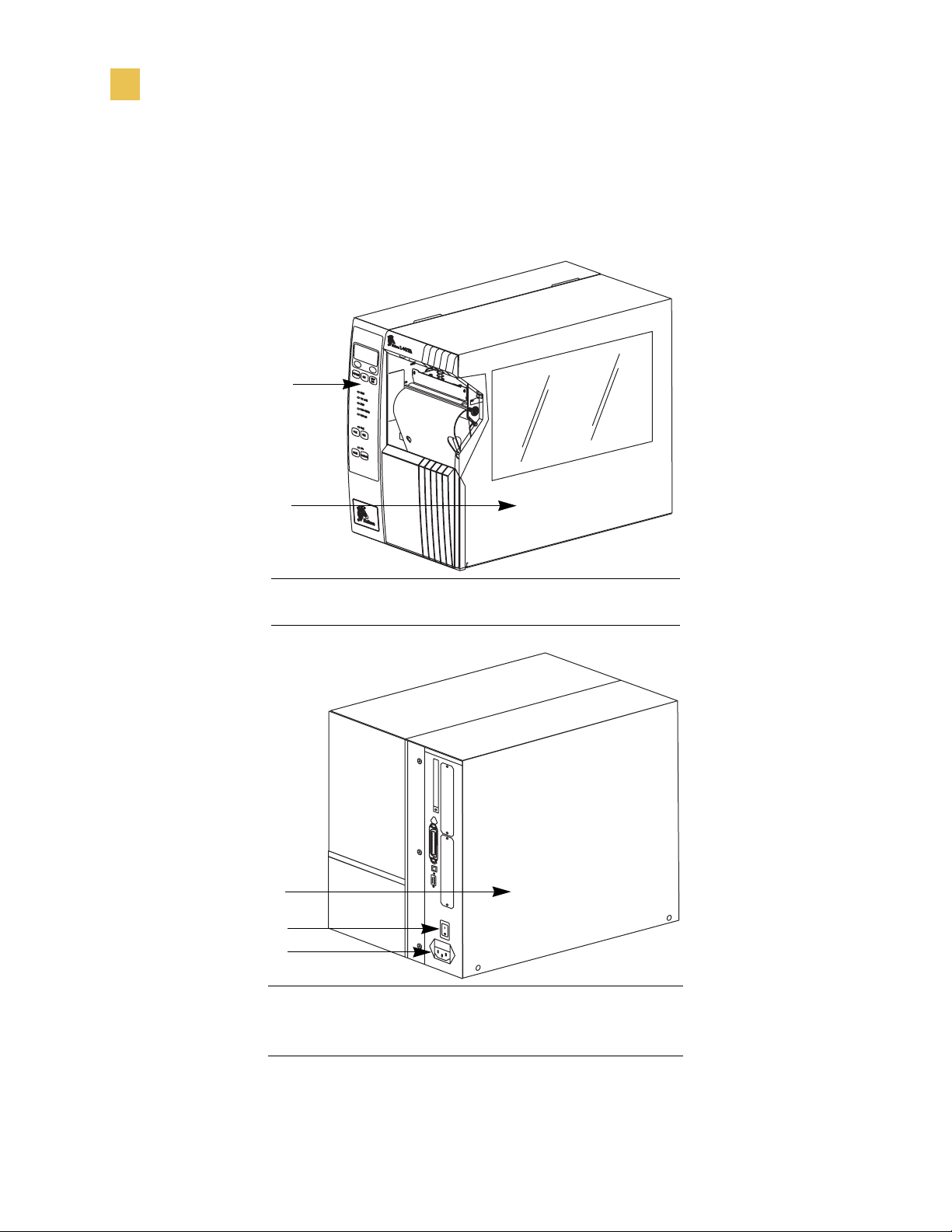
Exterior View
The following illustrations show the exterior of the printer.
1
2
Front panel
1
Media door
2
1
2
3
Electronics cover
1
Power switch
2
AC power cord connection
3
2 Bradyprinter THT X-Plus II Series User Guide
Page 31

Front Panel
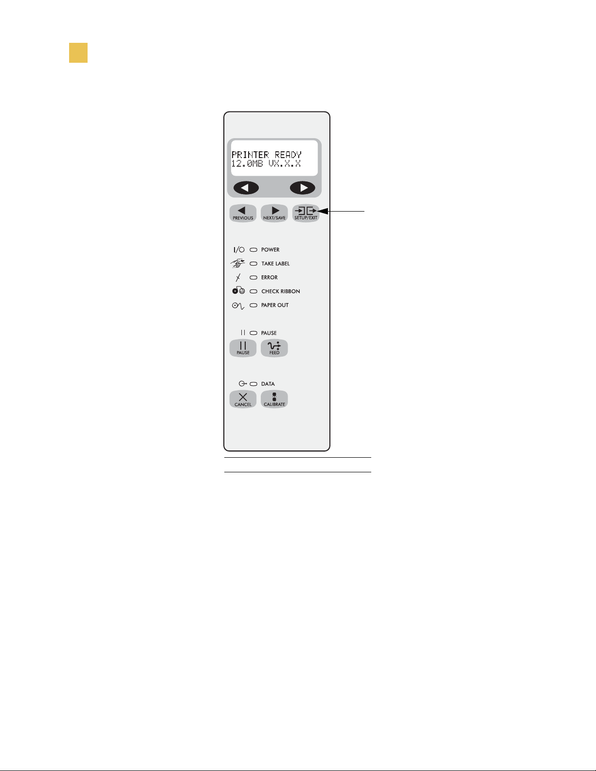
This illustration shows the buttons and lights on the front panel. For details, see Front
Panel Buttons on page 4 and Front Panel Lights on page 5.
Introduction
Front Panel
Bradyprinter THT X-Plus II Series User Guide 3
Page 32

Introduction
Front Panel
Front Panel Buttons
This table describes the function of the buttons shown in the illustration on page 2.
Button Details
LEFT OVAL Changes parameter values. Common uses are to increase/decrease a value,
answer yes or no, indicate on or off, scroll through several choices, input the
password, or set up the printer for a firmware download.
RIGHT
OVAL Changes parameter values. Common uses are to increase/decrease a value,
answer yes or no, indicate on or off, scroll through several choices, input the
password, or set up the printer for a firmware download.
PREVIOUS Scrolls to the previous parameter. Press and hold this button to scroll back
quickly through parameter sets.
NEXT/SAVE Scrolls to the next parameter. Press and hold this button to scroll forward
quickly through parameter sets.
SETUP/EXIT Enters and exits the setup mode.
PAUSE Starts and stops the printing process and allows other buttons to be used. If an
error messages is on the LCD, pressing this button removes the error.
FEED Forces the printer to feed a blank label each time the button is pressed.
• If the printer is not printing, one blank label immediately feeds.
• If the printer is printing, one blank label feeds after the current batch of
labels is complete.
CANCEL In the pause mode, this button cancels print jobs.
• If there are multiple print jobs in the print queue, press CANCEL once for
each print job to be deleted.
• To delete all print jobs, hold CANCEL for several seconds. The DATA light
turns off.
CALIBRATE This button can be used to calibrate the printer for the following:
• Media length
• Media type (continuous or non-continuous)
• Print mode (direct thermal or thermal transfer)
• Sensor values
For more information on calibration, see Calibrate the Printer on page 33.
4 Bradyprinter THT X-Plus II Series User Guide
Page 33

Front Panel Lights
This table details the lights shown in the illustration on page 2.
Light Details
Introduction
Front Panel
POWER
TAKE LABEL
ERROR
CHECK RIBBON
PAPER OUT
PAUS E
Indicates printer power status.
• Off — printer is off.
• On — printer is on.
• Off — Normal operation.
• Flashing — (Peel-Off Mode only.) The label is available. Printing is
paused until the label is removed.
Indicates printer operation.
• Off — printer is in Normal operation.
• Flashing — printer pauses until the label is removed.
• Off — Normal operation; ribbon (if used) is properly loaded.
• On — No media is under the label sensor. Printing is paused, the LCD
shows an error message, and the PAUSE light is on.
Indicates that labels need to be reloaded.
• Off — normal operation.
• On — all printing operations have stopped. Either PAUSE was pressed, a
pause command was included in the label format, the on-line verifier
detected an error, or a printer error was detected.
DATA
• Off — Normal operation. No data being received or processed.
• On/Blinking — Data processing or printing is taking place. Data is being
received.
Bradyprinter THT X-Plus II Series User Guide 5
Page 34

Introduction
Printer Components
Printer Components
This illustration shows a side view of the printer’s internal components.
Note • Depending on the printer options that you selected, your printer could look
slightly different. For more about printer options, go to www.bradyid.com.
123
14
13
12
11
10
4
5
6
9
7
8
6 Bradyprinter THT X-Plus II Series User Guide
Page 35

Printhead lever
1
Ribbon take-up spindle
2
Ribbon supply spindle
3
Ribbon dancer assembly (only on select models)
4
Media guide
5
Media dancer roller assembly
6
Media supply guide
7
Media supply hanger
8
Rewind spindle (optional)
9
Spindle hook
10
Lower roller
11
Snap plate
12
Platen roller
13
Tear-off bar
14
Introduction
Printer Components
Bradyprinter THT X-Plus II Series User Guide 7
Page 36

Introduction
Printer Components
8 Bradyprinter THT X-Plus II Series User Guide
Page 37

CHAPTER 2
Getting Started
This chapter provides the tasks that you must complete and the issues that you must
consider before you load and configure your printer.
Contents
Before You Begin . . . . . . . . . . . . . . . . . . . . . . . . . . . . . . . . . . . 10
Unpack and Inspect the Printer. . . . . . . . . . . . . . . . . . . . . . . . . 11
Report Shipping Damage . . . . . . . . . . . . . . . . . . . . . . . . . . . 11
Store or Reship the Printer . . . . . . . . . . . . . . . . . . . . . . . . . . 11
Select a Site for the Printer . . . . . . . . . . . . . . . . . . . . . . . . . . . . 12
Select a Surface . . . . . . . . . . . . . . . . . . . . . . . . . . . . . . . . . . 12
Provide Proper Operating Conditions . . . . . . . . . . . . . . . . . . 12
Allow Proper Space. . . . . . . . . . . . . . . . . . . . . . . . . . . . . . . . 12
Provide a Data Source . . . . . . . . . . . . . . . . . . . . . . . . . . . . . 12
Connect the Printer to a Power Source. . . . . . . . . . . . . . . . . . . 13
Power Cord . . . . . . . . . . . . . . . . . . . . . . . . . . . . . . . . . . . . . . 13
Communication Interfaces. . . . . . . . . . . . . . . . . . . . . . . . . . . . . 15
Data Cable Requirements . . . . . . . . . . . . . . . . . . . . . . . . . . . 16
Types of Media . . . . . . . . . . . . . . . . . . . . . . . . . . . . . . . . . . . . . 17
Continuous Media . . . . . . . . . . . . . . . . . . . . . . . . . . . . . . . . . 17
Non-Continuous Black Mark Media. . . . . . . . . . . . . . . . . . . . 17
Non-Continuous Web Media . . . . . . . . . . . . . . . . . . . . . . . . . 18
Ribbon. . . . . . . . . . . . . . . . . . . . . . . . . . . . . . . . . . . . . . . . . . . . 19
Bradyprinter THT X-Plus II Series User Guide 9
Page 38

Getting Started
Before You Begin
Before You Begin
Review this checklist, and resolve any issues before you begin setting up your printer.
When you are ready, continue with Printer Operation on page 21.
Unpack and Inspect Have you unpacked the printer and inspected it for
damage? If you have not, see Unpack and Inspect the Printer on page 11.
Select a Site Have you selected an appropriate location for the printer? If you
have not, see Select a Site for the Printer on page 12.
Attach Power Cord Do you have the correct power cord for your printer? If
you are unsure, see Power Cord on page 13. To attach the power cord and connect
the printer to a power source, see Connect the Printer to a Power Source
on page 13.
Connect to a Data Source Have you determined how the printer will be
connected to a data source (usually a computer)? For more information, see
Communication Interfaces on page 15.
Select Media Do you have the correct media for your application? If you are
unsure, see Types of Media on page 17.
Select Ribbon Do you need to use ribbon, and is the appropriate ribbon
available, if needed? If you are unsure, see Ribbon on page 19.
10 Bradyprinter THT X-Plus II Series User Guide
Page 39

Unpack and Inspect the Printer
When you unpack the printer, save all packing materials. When the printer is out of the
box, raise the printer’s media door, and remove the power cord.
Inspect the printer for possible damage incurred during shipment. Check all exterior
surfaces for damage. Raise the media door, and inspect the media compartment for
damage to components.
Report Shipping Damage
If you discover shipping damage upon inspection:
• Immediately notify the shipping company of the damage, and file a damage report
with them. Brady is not responsible for any damage incurred during shipment of
the equipment and does not repair this damage under warranty.
Getting Started
Unpack and Inspect the Printer
• Keep all packaging material for shipping company inspection.
• Notify your authorized Brady distributor.
Store or Reship the Printer
If you are not placing the printer into immediate operation, repackage it using the
original packing materials. You may store the printer under the following conditions:
• Temperature: –40° to 140°F (–40° to 60°C)
• Relative humidity: 5% to 85% non-condensing
If you must ship the printer, remove any ribbon and media from the supply spools to
avoid damaging the printer. Carefully pack the printer into the original container or a
suitable alternate container to avoid damage during transit.
Bradyprinter THT X-Plus II Series User Guide 11
Page 40

Getting Started
Select a Site for the Printer
Select a Site for the Printer
Consider the following when selecting an appropriate location for your printer.
Select a Surface
Select a solid, level surface of sufficient size and strength to accommodate the printer
and other equipment (such as a computer), if necessary. The choices include a table,
countertop, desk, or cart.
Provide Proper Operating Conditions
Because the printer was designed and is fabricated as an industrial-type unit, it
functions satisfactorily in a location that conforms to specified environmental and
electrical conditions, including a warehouse or factory floor. For more information on
the required conditions, see General Specifications on page 133.
The following table shows the temperature and relative humidity requirements for the
printer when it is operating.
Mode Temperature Relative Humidity
Thermal Transfer 41° to 104°F (5° to 40°C) 20 to 85% non-condensing
Direct Thermal 32° to 104°F (0° to 40°C) 20 to 85% non-condensing
Allow Proper Space
The printer should have enough space around it for you to be able to open the media
door. To allow for proper ventilation and cooling, leave open space on all sides of the
printer.
Caution • Do not place any padding or cushioning material behind or under the
printer because this restricts air flow and could cause the printer to overheat.
Provide a Data Source
If the printer will be located away from the data source, the selected site must provide
the appropriate connections to that data source. For more information on the types of
communication interfaces, see Communication Interfaces on page 15.
12 Bradyprinter THT X-Plus II Series User Guide
Page 41

Getting Started
Connect the Printer to a Power Source
Connect the Printer to a Power Source
Caution • For personnel and equipment safety, always use an approved
three-conductor power cord specific to the region or country intended for installation.
This cord must use an IEC 320 female connector and the appropriate region-specific
three-conductor grounded plug configuration.
To connect the printer to a power source, complete these steps:
1. Turn the printer power switch (located on the rear of the printer) to the Off (O)
position.
2. Plug the power cord into the mating connector on the rear of the printer.
3. Plug the other end of the power cord into the power source.
Power Cord
Depending on how your printer was ordered, a power cord may or may not be
included. If one is not included or if the one included is not suitable for your
requirements, refer to the following guidelines.
Your power cord must meed these standards:
• The overall length must be less than 9.8 ft (3.0 m).
• It must be rated for at least 5 A, 250 V.
• The chassis ground (earth) must be connected to ensure safety and reduce
electromagnetic interference.
The ground connection is handled by the third wire (earth) in the power cord as
shown in the following illustration.
1 2 3 4
AC power plug for your country
1
3-conductor HAR cable
2
IEC 320 connector
3
Neutral earth live in contact view
4
Bradyprinter THT X-Plus II Series User Guide 13
Page 42

Getting Started
Connect the Printer to a Power Source
• The AC power plug and the IEC 320 connector must bear the certification mark of
at least one of the known international safety organizations shown in this
illustration.
+
R
14 Bradyprinter THT X-Plus II Series User Guide
Page 43

Communication Interfaces
The way that you connect your printer to a data source depends on the communication
options installed in the printer. The standard communication interfaces are an RS-232
serial data port, a bi-directional parallel port, and a USB 2.0 port.
Note • RS-422 and RS-485 serial data ports are available through an adapter. A DB-25
cable and a USB 2.0 cable are also available.
The following illustration shows the location of the communication interfaces on the
back of the printer. For more information about these interfaces, see Data Ports
on page 55.
Getting Started
Communication Interfaces
1
2
3
Parallel port
1
Serial port
2
USB 2.0 port
3
Other options for connecting your printer to a data source include the following:
• The optional BradyConnect®PrintServer II, which enables the printer to be
connected to 10Base-T Ethernet networks.
• A wireless card socket option.
• The IBM® Twinax or IBM® Coax option for those applications that require them.
Bradyprinter THT X-Plus II Series User Guide 15
Page 44

Getting Started
Communication Interfaces
Data Cable Requirements
Data cables must be fully shielded and fitted with metal or metallized connector shells.
Shielded cables and connectors are required to prevent radiation and reception of
electrical noise.
To minimize electrical noise pickup in the cable:
• Keep data cables as short as possible.
• Do not bundle the data cables tightly with the power cords.
• Do not tie the data cables to power wire conduits.
Note • Brady printers comply with FCC Rules and Regulations, Part 15 for Class B
Equipment using fully shielded, 6.5 ft (2 m) data cables. Use of unshielded cables may
increase radiation above the Class B limits.
Note • RS-422 and RS-485 applications should use twisted shielded pairs as
recommended in the TIA/EIA-485 Specification.
16 Bradyprinter THT X-Plus II Series User Guide
Page 45

Types of Media
The printer can use media that is on rolls or in fan-folded stacks. The difference
between media types is in whether the media is continuous or non-continuous.
We strongly recommend the use of Brady-brand supplies for continuous high-quality
printing. A wide range of paper, polypropylene, polyester, and vinyl stock has been
specifically engineered to enhance the printing capabilities of the printer and to ensure
against premature printhead wear.
Note • Because print quality is affected by media and ribbon, printing speeds, and
printer operating modes, it is very important to run tests for your applications.
Continuous Media
Getting Started
Types of Media
Continuous media is one uninterrupted length of material that allows the image to be
printed anywhere on the label. The individual labels can be cut apart or stored in a roll
for later use.
This illustration shows a sample of continuous media.
Non-Continuous Black Mark Media
Non-continuous black mark media has black marks printed on the back, which
indicate the start and end of each label. This illustration shows a sample of
non-continuous black mark media.
Bradyprinter THT X-Plus II Series User Guide 17
Page 46

Getting Started
Types of Media
Non-Continuous Web Media
Non-continuous web media refers to individual labels that are separated by a gap,
notch, or hole. When you look at the media, you can tell where one label ends and the
next one begins.
Important • The life of the printhead may be reduced by the abrasion of exposed
!
paper fibers when using perforated media.
This illustration shows samples of non-continuous web media.
18 Bradyprinter THT X-Plus II Series User Guide
Page 47

Ribbon
The media determines whether you need to use ribbon and determines the minimum
width of the ribbon. Consider the following:
• Thermal transfer — ribbon needed.
• Direct thermal transfer — no ribbon needed.
Getting Started
Ribbon
The ribbon must be as wide as or wider than the media being used. If the ribbon is
narrower than the media, areas of the printhead are unprotected and subject to
premature wear.
When printing in direct thermal mode, ribbon is not used and should not be loaded
in the printer.
Bradyprinter THT X-Plus II Series User Guide 19
Page 48

Getting Started
Ribbon
20 Bradyprinter THT X-Plus II Series User Guide
Page 49

CHAPTER 3
Printer Operation
If you have completed the tasks and resolved the issues in the checklist in Before You
Begin on page 10, follow the instruction in this chapter to load and calibrate your
printer and to print a configuration label.
Contents
Load the Printer. . . . . . . . . . . . . . . . . . . . . . . . . . . . . . . . . . . . . 22
Load Roll Media . . . . . . . . . . . . . . . . . . . . . . . . . . . . . . . . . . 22
Load Fanfold Media. . . . . . . . . . . . . . . . . . . . . . . . . . . . . . . . 24
Load Ribbon . . . . . . . . . . . . . . . . . . . . . . . . . . . . . . . . . . . . . 26
Remove Used Ribbon . . . . . . . . . . . . . . . . . . . . . . . . . . . . . . 30
Print a Configuration Label . . . . . . . . . . . . . . . . . . . . . . . . . . . . 31
Calibrate the Printer . . . . . . . . . . . . . . . . . . . . . . . . . . . . . . . . . 33
Adjust Sensors . . . . . . . . . . . . . . . . . . . . . . . . . . . . . . . . . . . . . 34
Media and Ribbon Sensor Calibration. . . . . . . . . . . . . . . . . . 34
Transmissive (Media) Sensors . . . . . . . . . . . . . . . . . . . . . . . 36
Adjust the Printhead . . . . . . . . . . . . . . . . . . . . . . . . . . . . . . . . . 39
Bradyprinter THT X-Plus II Series User Guide 21
Page 50

Printer Operation
Load the Printer
Load the Printer
This section gives you a series of instructions to load labels and ribbon (if used). The
instructions that follow are for a standard printer in Tear-Off Mode. To choose
different printing modes, see Print Modes on page 41.
Caution • Be sure the printer is Off (O) if you have connected the power cable.
Load Roll Media
Roll media feeds through the printer from the media hanger or media supply spindle.
This illustration identifies the components of the printer that you need to be familiar
with to load roll media.
1
2
Printhead lever
1
Media guide
2
Media back plate
3
Optional media spindle
4
3
4
22 Bradyprinter THT X-Plus II Series User Guide
Page 51

Printer Operation
1
Load the Printer
To load roll media, complete these steps:
1. Open the printhead.
2. Slide the media guide away from the printer frame. You might need to loosen the
media guide screw.
3. Put the roll of media on the media hanger.
4. Push the label core toward the printer frame. The labels must be aligned with the
label core.
5. Feed the media under the media guide roller and under the printhead.
6. Do you have the Cutter option?
• No — continue with the next step.
• Yes — feed the media through the cutter.
Caution • The cutter blade is sharp. Do not rub or touch the blade
with your fingers.
7. Adjust the media supply guide so it is just touching, but does not restrict, the edge
of the media. The labels should lie flat as shown in the illustration.
3
2
Printhead
1
Media guide roller
2
Labels/media
3
8. Are you using direct thermal labels?
• Yes — close the printhead and go to Print a Configuration Label on page 31.
• No — go to Load Ribbon on page 26.
Bradyprinter THT X-Plus II Series User Guide 23
Page 52

Printer Operation
Load the Printer
Load Fanfold Media
Fanfold media feeds through either the bottom or rear access slot from outside the
printer. The media hanger and media supply spindle are not used with fanfold media.
To load fanfold labels, complete these steps:
1. Slide the printhead lever to the Open position.
2. Slide the media guide as far from the printer frame as possible.
3. How do you want to feed the fanfold labels?
• From the bottom slot in the printer body.
This illustration shows the printer with fanfold labels loaded through the
bottom slot.
1
Printhead lever
1
(shown in the Open position)
Media guide
2
Fanfold labels
3
2
3
24 Bradyprinter THT X-Plus II Series User Guide
Page 53

Printer Operation
Load the Printer
• From the rear slot in the printer body.
This illustration shows the printer with fanfold labels loaded through the rear
slot.
1
2
3
Printhead lever (shown in the Open position)
1
Media guide
2
Fanfold labels
3
4. Do you have the Cutter option?
• No — continue with the next step.
• Yes — feed the fanfold media through the cutter.
Caution • The cutter blade is sharp. Do not rub or touch the blade
with your fingers.
5. Adjust the media guide so it just touches, but does not restrict, the edge of the
labels. The labels should lie flat.
6. Are you using direct thermal labels?
• Yes — close the printhead and go to Print a Configuration Label on page 31.
• No — go to Load Ribbon on page 26.
Bradyprinter THT X-Plus II Series User Guide 25
Page 54

Printer Operation
Load the Printer
Load Ribbon
Before you load ribbon, make sure that the labels that you are using need ribbon. Only
thermal transfer labels require ribbon. Do not load ribbon if the printer is to be used
with direct thermal labels.
Caution • Use ribbon that is wider than the thermal transfer media. If the
printhead is not protected by the ribbon, the resulting abrasion from the media
may cause premature printhead wear.
A ribbon leader makes it easier to load and unload ribbon. Make a leader for your
ribbon roll if it does not already have one.
To make a ribbon leader, complete these steps:
1. Unroll the ribbon about 6 in. (15 cm).
2. Tear off a strip of labels and backing about 6 in. (15 cm) long from the label roll.
3. Peel a label from the backing.
4. Overlap the ribbon and the backing with the ribbon on top, and use the label to tape
them together. This serves as a ribbon leader.
26 Bradyprinter THT X-Plus II Series User Guide
Page 55

Printer Operation
Load the Printer
To load the ribbon, complete these steps:
1. Align the segments of the ribbon supply spindle as shown in the following
illustration.
2. Place the roll of ribbon on the ribbon supply spindle, and push the core as far back
as it can go. The following illustration shows the printer components that are
mentioned in this procedure.
1 2
3
7
4
6
5
Top roller
1
Ribbon take-up spindle
2
Ribbon supply spindle
3
Ribbon guide roller
4
Ribbon leader attached to ribbon
5
Platen roller (not shown)
6
Printhead lever
7
(shown in the Open position)
3. If the printhead is closed, open it using the printhead lever.
4. Thread the ribbon leader and attached ribbon under the ribbon guide roller, through
the print mechanism, and past the platen roller.
Note • For the BP THT 360X-Plus II, thread the leader first through the
ribbon dancer roller assembly.
Bradyprinter THT X-Plus II Series User Guide 27
Page 56

Printer Operation
Load the Printer
5. Pull the ribbon leader over the printhead and above the top roller as shown in the
following illustration.
2
1
Ribbon leader
1
Printhead
2
6. Bring the ribbon leader and ribbon under the ribbon take-up spindle, and wrap
them around the spindle. The following illustration shows the ribbon leader
wrapped around the ribbon take-up spindle.
1
2
Ribbon leader
1
Ribbon take-up spindle
2
7. Turn the spindle counterclockwise until the ribbon stays on the spindle.
28 Bradyprinter THT X-Plus II Series User Guide
Page 57

Printer Operation
Load the Printer
8. Close the printhead.
The following illustration shows how your printer should look with the media and
ribbon loaded.
9. To remove the ribbon, refer to Remove Used Ribbon on page 30.
Bradyprinter THT X-Plus II Series User Guide 29
Page 58

Printer Operation
Load the Printer
Remove Used Ribbon
When the ribbon has run out or must be changed, remove the used ribbon from the
take-up spindle. This illustration shows the ribbon take-up spindle.
1 2
Used ribbon
1
Ribbon take-up spindle
2
Ribbon release bars
3
Notch in ribbon take-up spindle
4
Arrow on ribbon take-up spindle
5
Ribbon release knob
6
3
4
To remove used ribbon, complete these steps:
1. Open the printhead.
5
6
2. Has the ribbon run out?
• Yes — continue with the next step.
• No — tear or cut the ribbon as close to the ribbon take-up spindle as possible.
Caution • Do not cut through the ribbon that is on the take-up spindle
because you may damage the spindle. Use the release knob to slide the ribbon
off of the spindle.
3. While holding the ribbon take-up spindle, turn the ribbon release knob clockwise
until it stops. This causes the ribbon release bars to pivot down, easing the
spindle’s grip on the used ribbon.
4. Slide the used ribbon off of the ribbon take-up spindle.
5. Align the arrow on the ribbon take-up spindle knob with the notch in the ribbon
take-up spindle.
6. To load new ribbon, see Load Ribbon on page 26.
30 Bradyprinter THT X-Plus II Series User Guide
Page 59

Print a Configuration Label
When you have loaded the media and ribbon (if necessary), print a configuration label
to use as a record of your printer settings. Keep the configuration label for baseline
information on your printer when troubleshooting printing problems.
Caution • For personal and equipment safety, always use an approved threeconductor power cord specific to the region or country intended for installation. This
cord must use an IEC 320 female connector and the appropriate region-specific threeconductor grounded plug configuration.
To print a configuration label, complete these steps:
1. Connect the power cord to the power connection on the back of the printer.
2. To confirm the power connection, turn the printer On (I).
The printer performs the power-up self test (POST). When the test is complete,
PRINTER READY displays on the front panel LCD.
Printer Operation
Print a Configuration Label
3. Does the front panel LCD display PRINTER READY?
• Yes — continue with the next step.
• No — go to Troubleshooting on page 111.
4. Turn the printer Off (O).
5. Press and hold CANCEL while turning the printer On (I).
6. Release CANCEL when the DATA light turns off (approximately five seconds).
The configuration label prints. A sample label, which may look different than
yours, is shown below.
Bradyprinter THT X-Plus II Series User Guide 31
Page 60

Printer Operation
Print a Configuration Label
7. Did the label print?
• Yes, a configuration label printed. Connect the printer to your data source.
Communication can be handled in many different ways. More information
about the standard interfaces is available in Standard Ports on page 56.
• No, a label did not print. Sensors out of position is a common cause of printing
problems. Refer to Adjust Sensors on page 34. For additional assistance, refer
to Troubleshooting on page 111.
32 Bradyprinter THT X-Plus II Series User Guide
Page 61

Calibrate the Printer
There are five different ways that the printer can be calibrated. You may calibrate the
printer as needed.
• Auto-calibration occurs when the printer feeds media after the printhead is closed
and when the printer is first turned on (see Media Power Up on page 89 and Head
Close on page 89 for options). The printer automatically sets the value it detects
for the spaces between labels. This type of calibration also happens as part of both
the sensor profile and media and ribbon sensor calibration procedures.
• Long Calibration, which you select by pressing PAUSE then CALIBRATE,
calibrates the printer for media length, media type (continuous or non-continuous),
and print mode (thermal or direct thermal transfer) and updates the sensor values.
• Short Calibration, which you select by pressing just CALIBRATE, uses current
sensor values rather than detecting the spaces between labels and resetting the
sensors. This calibration sequence uses fewer labels than the long calibration
sequence, but it is less reliable because the values that are stored in the sensors
could be incorrect.
Printer Operation
Calibrate the Printer
Note • If you press CALIBRATE and nothing happens, you may need to
upgrade your firmware. Print a configuration label to see which version of
firmware that is installed on your printer. To upgrade your firmware or to
check if you have the latest version, go to
http://www.bradyid.com/brady/isdwebv2.nsf/webpages/downloads.
• Sensor Profile Calibration, which you select through the front panel,
auto-calibrates the printer and prints a media sensor profile. See Sensor Profile
on page 83 for instructions.
• Media and Ribbon Sensor Sensitivity Calibration, which you select through the
front panel, resets the sensitivity of the sensors to detect correctly the media and
ribbon that you are using. See Media and Ribbon Sensor Calibration on page 34
for instructions. If you change the type of ribbon and/or media, you might need to
reset the sensitivity of the media and ribbon sensors. When the sensors are at their
new sensitivity, the printer performs an auto-calibration.
Bradyprinter THT X-Plus II Series User Guide 33
Page 62

Printer Operation
Adjust Sensors
Adjust Sensors
This section describes how to adjust and calibrate sensors.
Media and Ribbon Sensor Calibration
Media and ribbon sensor calibration is one of the most common adjustments to the
printer settings. This procedure is performed through the front panel.
Indications that the sensitivity may need to be reset are:
• The CHECK RIBBON light is on even though the ribbon is properly installed.
• Non-continuous labels are being treated as continuous labels.
Note • Before you begin the calibration procedure, make sure that the maximum
length is set to a value 1 in. (25.4 mm) greater than the length of the labels that you are
using. If the maximum length is set to a lower value, the calibration process assumes
that continuous media is in the printer.
!
Important • This procedure must be followed exactly as presented. All of the steps
must be performed even if only one of the sensors requires adjustment. You may press
the left oval at any step in this procedure to cancel the procedure.
To adjust the sensitivity of media and ribbon sensors, complete
these steps:
1. From the front panel, press the right oval to start the calibration procedure.
The LOAD BACKING prompt displays.
2. Open the printhead.
3. Remove approximately 8 in. (203 mm) of labels from the media backing, and pull
the media into the printer so that only the backing is between the media sensors.
4. Leave the printhead open.
5. Press the right oval to continue.
The REMOVE RIBBON prompt displays.
6. Remove the ribbon.
7. Close the printhead.
34 Bradyprinter THT X-Plus II Series User Guide
Page 63

Printer Operation
Adjust Sensors
8. Press the right oval to continue.
The message CALIBRATING PLEASE WAIT displays.
The printer adjusts the scale (gain) of the signals that it receives from the media
and ribbon sensors. On the sensor profile, this essentially corresponds to moving
the peak of the graph up or down to optimize the readings for your application (for
more information, see Sensor Profile on page 83).
When calibration is complete, RELOAD ALL displays.
9. Open the printhead and pull the media forward until a label is positioned under the
media sensor.
10. Reload the ribbon back into to its proper position.
11. Close the printhead.
12. Press the right oval to continue.
The printer does a calibration equivalent to pressing CALIBRATE; during this
process, the printer determines the label length. To see the new readings on the
new scale, print a sensor profile.
Bradyprinter THT X-Plus II Series User Guide 35
Page 64

Printer Operation
Adjust Sensors
Transmissive (Media) Sensors
The transmissive sensor consists of two sections: a light source (the lower media
sensor) and a light sensor (the upper media sensor). The media passes between
the two. The upper media sensor can be positioned along the inside half of the media
(the side closest to the back of the printer) or the outside half of the media (the side
farthest from the back of the printer).
Adjust these sensors only when the printer cannot detect the top of the label. The front
panel LCD displays ERROR CONDITION PAPER OUT, even though there are labels loaded
in the printer.
To adjust the upper media sensor for the inside half of the
media, complete these steps:
1. Remove the ribbon (if ribbon is used).
2. Locate the upper media sensor as shown in the following illustration. The upper
media sensor eye is directly below the adjustment screw head.
1
Upper media sensor adjustment screw
1
Upper media sensor
2
2
3. Slightly loosen the upper media sensor adjustment screw using a Phillips-head
screwdriver.
4. Using the tip of the screwdriver, slide the upper sensor along the slot to the desired
position (for non-continuous media with a notch or hole in the media, the sensor
must be directly above the notch or hole).
5. Tighten the adjustment screw to secure the upper media sensor.
36 Bradyprinter THT X-Plus II Series User Guide
Page 65

Printer Operation
Adjust Sensors
To adjust the upper media sensor for the outside half of the
media:
1. Remove the ribbon (if ribbon is used).
2. Locate the upper media sensor. The upper media sensor eye is directly below the
adjustment screw head.
3. Remove the upper media sensor adjustment screw using a Phillips-head
screwdriver.
4. Lift the upper media sensor assembly from the slot, and move it and the wire cover
to the outside slot. Carefully pull the wires through the cable tie. You may need to
set aside the sensor wire cover if the adjustment is too far to the outside.
5. Replace and slightly tighten the adjustment screw.
6. Slide the upper media sensor along the slot to the desired position (for
non-continuous media with a notch or hole in the media, the sensor must be
directly above the notch or hole).
7. Tighten the adjustment screw.
8. Make sure that the wires are routed back into the groove of the media sensor
bracket.
Bradyprinter THT X-Plus II Series User Guide 37
Page 66

Printer Operation
Adjust Sensors
To adjust the lower media sensor, complete these steps:
1. Locate the lower media sensor assembly under the rear roller. (The sensor is a
spring clip holding a circuit board.)
1
Lower media sensor
1
2. Slide the sensor until the two brass-colored infrared emitters are under the upper
media sensor. Gently pull wires out as needed (wires should have a little slack).
3. If you move the sensor inward and a large loop of wire develops, remove the
electronics cover from the side of the printer, and gently pull the wires through.
Clamp the wires so that they do not rub any drive belts.
38 Bradyprinter THT X-Plus II Series User Guide
Page 67

Adjust the Printhead
Important • Print quality depends on the labels and ribbon used as well as the toggle
!
pressure. Make sure your labels and ribbon are right for your application.
• Direct thermal labels do not need ribbon.
• Thermal transfer labels need thermal transfer ribbon.
Printhead pressure and the darkness setting affect print quality. If the darkness setting
is too high for the labels and ribbon being used, it causes premature printhead wear. If
the toggle pressure is not even, labels and ribbon may slip.
Toggle adjustment may be needed if printing is too light on one side or if thick labels
are used. Make sure that the toggles are positioned properly.
The toggles should be positioned so they provide even pressure on the labels. The
toggles are positioned by sliding them to the desired location. If the labels are too
narrow to fit both toggles, position one toggle over the center of the labels and
decrease the pressure on the unused toggle.
Printer Operation
Adjust the Printhead
If positioning the toggles properly does not solve the problem, adjust printhead
pressure. Printhead life can be maximized by using the lowest pressure that produces
the desired print quality.
Caution • Observe proper electrostatic safety precautions when handling any staticsensitive components such as circuit boards and printheads.
To adjust printhead pressure, complete these steps:
1. Print some labels at 2.4 in. (61 mm) per second by running the PAUSE Self Test
on page 125.
2. While printing labels, use the front panel controls to lower the darkness setting
until the labels are printing gray instead of black.
3. Loosen the locking nuts at the top of the toggle assemblies.
Bradyprinter THT X-Plus II Series User Guide 39
Page 68

Printer Operation
Adjust the Printhead
1
2
Locking nuts
1
Adjusting nuts
2
4. Some media types require higher pressure to print well. For these media types,
increase or decrease pressure using the adjusting nuts until the left and right edges
of the printed area are equally dark.
5. Increase the darkness level using the front panel controls until the printing is clear.
6. Tighten the locking nuts.
40 Bradyprinter THT X-Plus II Series User Guide
Page 69

CHAPTER 4
Print Modes
This chapter describes the available print modes.
Contents
Select a Print Mode . . . . . . . . . . . . . . . . . . . . . . . . . . . . . . . . . . 42
Remove Backing from Rewind Spindle . . . . . . . . . . . . . . . . . . . 53
Tear-Off Mode . . . . . . . . . . . . . . . . . . . . . . . . . . . . . . . . . . . . 42
Peel-Off Mode . . . . . . . . . . . . . . . . . . . . . . . . . . . . . . . . . . . . 43
Cutter Mode. . . . . . . . . . . . . . . . . . . . . . . . . . . . . . . . . . . . . . 45
Rewind Mode . . . . . . . . . . . . . . . . . . . . . . . . . . . . . . . . . . . . 47
Rewind Mode with Cutter Option. . . . . . . . . . . . . . . . . . . . . . 50
Bradyprinter THT X-Plus II Series User Guide 41
Page 70

Print Modes
Select a Print Mode
Select a Print Mode
The options on your printer may let you set up additional print modes. Use the front
panel controls to set up the printer to the print mode that you wish to use.
The following are the available print mode selections:
• Tear-off
• Peel-off
• Cutter
• Rewind
• Applicator (used only if a machine will apply printed labels to something)
To select a print mode, complete these steps:
1. From the front panel, press SETUP/EXIT.
2. Press NEXT/SAVE until the LCD reads PRINT MODE.
3. Use the right or left oval to scroll though the choices. Be sure to select a print mode
that your hardware supports—some of the selections displayed are for optional
printer features.
4. To save your selection, press SETUP/EXIT.
Tear-Off Mode
See Load the Printer on page 22 to set up labels in Tear-Off Mode.
42 Bradyprinter THT X-Plus II Series User Guide
Page 71

Peel-Off Mode
Peel-Off Mode advances one label at a time. The printer does not print another label
until the first label is removed. The TAKE LABEL light flashes until the label is
removed. The backing is wound on the rewind spindle, but the rewind plate is
not used.
This illustration shows the printer loaded with labels in Peel-Off Mode.
Print Modes
Select a Print Mode
10
1
9
8
1
Printhead lever
2
Media guide
3
Media supply guide
4
Media
5
Guide plate
6
Spindle hook
7
Rewind spindle
8
Label backing
9
Tear-off bar
10
Printed label
2 3
7 6
5
4
Bradyprinter THT X-Plus II Series User Guide 43
Page 72

Print Modes
Select a Print Mode
To set up the printer in Peel-Off Mode, complete these steps:
1. Remove the rewind plate (if installed) from the front of the printer. Store it on the
two mounting screws on the inside of the front panel.
2. From the front panel, select Peel-Off Mode.
3. Open the printhead.
4. Slide the media guide and media supply guide as far from the printer frame as
possible.
5. Flip down the media supply guide.
6. Put the roll of media on the media hanger.
7. Push the label core toward the printer frame. The labels must be aligned with the
label core.
8. Feed the media under the media guide roller and under the printhead.
9. Adjust the media supply guide so it is just touching the edge of the media.
10. When loading labels, allow approximately 36 in
. (915 mm) of labels to extend past
the tear-off/peel-off bar. Remove all labels from this portion to create a leader.
11. Remove the hook from the rewind spindle. If you are using a core, slide it onto the
rewind spindle until it is flush against the guide plate.
12. Wind the label backing around either the 3 in. (76 mm) core or the rewind spindle
and reinstall the hook.
13. Flip up the media supply guide. Slide in the media guide and media supply guide
so they just touch, the edge of the labels. The labels should lie flat.
14. Before closing the printhead, make sure that:
• The labels are positioned against the inside guides.
• The labels are taut and parallel with the pathway when wound onto the rewind
spindle or core.
15. Close the printhead.
The backing winds on the rewind spindle or core.
44 Bradyprinter THT X-Plus II Series User Guide
Page 73

Cutter Mode
A cutter is a rotating knife with a self-sharpening blade that is attached to the front of
the printer. The cutter is used to cut individual labels as they are printed. See
www.bradyid.com for more information about the cutter option.
This illustration shows the printer loaded with labels in Cutter Mode.
Print Modes
Select a Print Mode
1
5
Printhead lever
1
Media guide
2
Media supply guide
3
Media
4
Cutter
5
2
4
3
To set up the printer in Cutter Mode, complete these steps:
1. Turn the printer On (I).
2. From the front panel, select Cutter Mode.
3. Open the printhead.
4. Slide the media guide and media supply guide as far from the printer frame as
possible.
5. Flip down the media supply guide.
6. Put the roll of media on the media hanger.
7. Push the label core toward the printer frame. The labels must be aligned with the
label core.
8. Feed the media under the media guide roller and under the printhead.
Bradyprinter THT X-Plus II Series User Guide 45
Page 74

Print Modes
Select a Print Mode
Caution • The cutter blade is sharp. Do not rub or touch the blade with your fingers.
9. Feed the labels through the cutter mechanism.
10. Flip up the media supply guide.
11. Slide in the media guide and media supply guide so they just touch, but do not
restrict, the edge of the roll.
12. Before closing the printhead, make sure that:
• The labels are positioned against the inside guides.
• The labels are taut and parallel with the pathway when wound onto the rewind
spindle or core.
13. Close the printhead.
46 Bradyprinter THT X-Plus II Series User Guide
Page 75

Rewind Mode
Rewind Mode allows the media to be wound on a core after printing.
The following illustration shows the printer loaded with labels in Rewind Mode.
Print Modes
Select a Print Mode
1
9
8
1
Printhead lever
2
Media guide
3
Media supply guide
4
Labels
5
Guide plate
6
Spindle hook
7
Rewind spindle
8
Rewind plate
9
Printed labels
2 3
7 6
5
4
Bradyprinter THT X-Plus II Series User Guide 47
Page 76

Print Modes
Select a Print Mode
To install the rewind plate, complete these steps:
1. Remove the rewind plate from its storage location inside the printer.
2. Position the rewind plate so that the lip on the attached hook plate points down.
3. Insert the hook plate lip 1/2 in. (13 mm) into the lower slot in the side plate.
4. Align the upper end of the rewind plate with the matching slot in the side plate.
5. Slide in the rewind plate until it stops against the printer’s main frame.
This illustration shows the rewind plate and where it hooks to the printer.
1
Slots
1
Rewind plate
2
Lip
3
Adjustable hook plate
4
2
3
4
48 Bradyprinter THT X-Plus II Series User Guide
Page 77

Print Modes
Select a Print Mode
To set up the printer in Rewind Mode, complete these steps:
1. If you have not already done so, install the rewind plate.
2. From the front panel, select Rewind Mode.
3. Open the printhead.
4. Slide the media guide and media supply guide as far from the printer frame as
possible. Flip down the media supply guide.
5. Put the roll of media on the media hanger.
6. Push the label core toward the printer frame. The labels must be aligned with the
label core.
7. Feed the media under the media guide roller and under the printhead.
8. Adjust the media supply guide so it is just touching the edge of the media.
9. When loading labels, allow approximately 36 in. (915 mm) of labels to extend past
the printhead. Remove all labels from this portion to create a leader.
10. Remove the hook from the rewind spindle. If you are using a core, slide it onto the
rewind spindle until it is flush against the guide plate.
11. Wind the label backing around either the 3 in. (76 mm) core or the rewind spindle.
Reinstall the hook.
12. Flip up the media supply guide. Slide in the media guide and media supply guide
so they just touch the edge of the labels. The labels should lie flat.
13. Before closing the printhead, make sure that:
• The labels are positioned against the inside guides.
• The labels are taut and parallel to the pathway when wound onto the rewind
spindle or core.
14. Close the printhead.
The labels wind on the rewind spindle or core.
Bradyprinter THT X-Plus II Series User Guide 49
Page 78
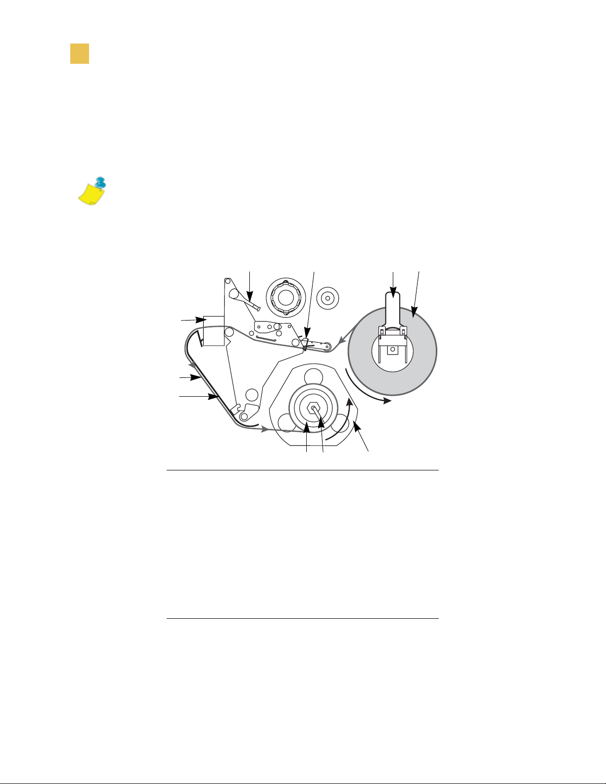
Print Modes
Select a Print Mode
Rewind Mode with Cutter Option
Printers with the cutter option can use the Rewind Mode to print and save a roll of
labels. See www.bradyid.com for more information about the cutter option.
Note • Rewind Mode cannot be used with the cutter option on the
BP THT 300X-Plus II and 600X-Plus II.
This illustration shows the printer loaded with labels in Rewind Mode with the cutter
option.
10
9
8
Printhead lever
1
Media guide
2
Media supply guide
3
Labels
4
Rewind spindle
5
Guide plate
6
Spindle hook
7
Rewind plate
8
Printed label
9
Cutter
10
1
2
7 6
5
4
3
50 Bradyprinter THT X-Plus II Series User Guide
Page 79

Print Modes
Select a Print Mode
To set up the Rewind Mode for printers with the cutter option,
complete these steps:
1. Turn the printer On (I).
The printer feeds out and cuts one label.
2. From the front panel, select Rewind Mode.
3. Remove the rewind plate from its storage location in front of the print mechanism
inside the media compartment.
4. Invert the rewind plate so that the lip on the attached hook plate points down.
5. Insert the hook plate lip 1/2 in. (13 mm) into the lower opening in the side plate.
Slide in the rewind plate until it stops against the printer’s main frame.
6. Insert the two small tabs on the rewind plate into the corresponding slots in the
cutter support bracket. (The rewind plate should spring into the proper position.)
7. Open the printhead.
8. Slide the media guide and media supply guide as far from the printer frame as
possible.
9. Flip down the media supply guide.
10. Put the roll of media on the media hanger.
11. Push the label core toward the printer frame. The labels must be aligned with the
label core.
12. Feed the media under the media guide roller and under the printhead.
Caution • The cutter blade is sharp. Do not rub or touch the blade with your fingers.
13. Feed the labels through the cutter mechanism.
14. When loading labels, allow approximately 36 in. (915 mm) of labels to extend past
the printhead. Remove all labels from this portion to create a leader.
15. Adjust the media supply guide so it is just touching the edge of the media.
16. Remove the hook from the rewind spindle.
17. If you are using a core, slide it onto the rewind spindle until it is flush against the
guide plate.
18. Wind the label backing around either the 3 in. (76 mm) core or the rewind spindle.
19. Reinstall the hook.
20. Flip up the media supply guide.
Bradyprinter THT X-Plus II Series User Guide 51
Page 80

Print Modes
Select a Print Mode
21. Slide in the media guide and media supply guide so they just touch, but do not
restrict, the edge of the roll.
22. Before closing the printhead, make sure that:
• The labels are positioned against the inside guides.
• The labels are taut and parallel with the pathway when wound onto the rewind
spindle or core.
23. Close the printhead.
The labels wind on the rewind spindle or core.
52 Bradyprinter THT X-Plus II Series User Guide
Page 81

Remove Backing from Rewind Spindle
Remove Backing from Rewind Spindle
Rewind Mode and Peel-Off Mode use the rewind spindle. The label backing must be
removed every time you change labels for the printer to work correctly.
Important • It is not necessary to turn off the power to remove backing from the
!
rewind spindle. If power is turned off, all label formats and images, as well as any
temporarily saved parameter settings stored in the printer’s internal memory, are lost.
When power is turned back on, these items must be reloaded.
To remove label backing from the rewind spindle, complete
these steps:
1. Have the labels run out?
• Yes — continue with the next step.
Print Modes
• No — unwind approximately 36 in. (915 mm) of backing from the rewind
spindle. Cut or tear it off at the spindle.
2. Pull out the spindle hook.
3. Slide the backing off of the rewind spindle and discard.
4. Replace the spindle hook.
Bradyprinter THT X-Plus II Series User Guide 53
Page 82

Print Modes
Remove Backing from Rewind Spindle
54 Bradyprinter THT X-Plus II Series User Guide
Page 83

CHAPTER 5
Data Ports
This chapter describes the standard communication ports on the printer.
Contents
Standard Ports. . . . . . . . . . . . . . . . . . . . . . . . . . . . . . . . . . . . . . 56
Parallel Port. . . . . . . . . . . . . . . . . . . . . . . . . . . . . . . . . . . . . . 56
Serial Port . . . . . . . . . . . . . . . . . . . . . . . . . . . . . . . . . . . . . . . 58
USB 2.0 Port . . . . . . . . . . . . . . . . . . . . . . . . . . . . . . . . . . . . . 64
Bradyprinter THT X-Plus II Series User Guide 55
Page 84

Data Ports
Standard Ports
Standard Ports
The different ports available to connect the printer to your computer or network
include:
• Parallel
• Serial RS-232
• USB
Parallel Port
When communicating via the parallel port, the values selected must be the same as
those used by the host equipment connected to the printer. Port selection for status
information is determined by the channel sending the request. The parallel port can be
set for bidirectional or unidirectional communication. The default setting is
bidirectional.
A standard 36-pin parallel connector (as shown below) is available on the back of the
printer for connection to the data source.
56 Bradyprinter THT X-Plus II Series User Guide
Page 85

Data Ports
Standard Ports
The following table shows the pin configuration and function of a standard computerto-printer parallel cable.
36-Pin
Description
Connectors
1 nStrobe/HostClk
2–9 Data Bits 1–8
10 nACK/PtrClk
11 Busy/PtrBusy
12 PError/ACKDataReq
13 Select/Xflag
14 nAutoFd/HostBusy
15 Not used
16, 17 Ground
18 +5 V at 750 mA
The maximum current draw may be limited by option configuration.
19–30 Ground
31 ninit
32 nFault/NDataAvail
33, 34 Not used
35 +5 V through a 1.8 KΩ Resistor
36 NSelectin/1284 active
Bradyprinter THT X-Plus II Series User Guide 57
Page 86

Data Ports
Standard Ports
Serial Port
To communicate using the serial data port of the printer, you must choose the number
of data and stop bits, parity, and handshaking. Parity applies only to data transmitted
by the printer because the parity of received data is ignored.
The values selected must be the same as those used by the host equipment connected
to the printer. Default settings are 9600 baud, 8 data bits, 1 stop bit, no parity, and
XON/XOFF.
Connect the serial data cable to the female DB-9 connector (shown below) on the back
panel of the printer.
Use a DB-9 to DB-25 interface module for all RS-232 connections through a DB-25
cable. An interface module is required for RS-422/RS-485 interface support
(see RS-422/RS-485 Interconnections on page 63).
Note • For all RS-232 input and output signals, the printer follows the specifications
of the Electronics Industries Association (EIA) RS-232 and the Consultative
Committee for International Telegraph and Telephone (CCITT) V.24.
58 Bradyprinter THT X-Plus II Series User Guide
Page 87

Data Ports
Standard Ports
Serial Pin Configuration
The table below shows the pin configuration and function of the rear panel serial data
connector on the printer.
Pin No. Name Description
1 — Not connected
2 RXD Receive data—data input to printer
3 TXD Transmit data—data output from printer
4 DTR Data terminal ready—output from printer
5 SG Signal ground
6 DSR Data set ready—input to printer
7 RTS Request to send—output from printer
8 CTS Clear to send—input to printer
9 +5 VDC +5 VDC signal output
Note • This pin is also available as a +5 VDC power
source at 750 mA. The maximum current draw may be
limited by option configuration. To enable this
capability, a jumper on the printer’s main logic board
needs to be installed on JP1, pins 2 and 3.
Bradyprinter THT X-Plus II Series User Guide 59
Page 88

Data Ports
Standard Ports
RS-232 Interface Connections
Direct Connection to a Computer
The printer is configured as Data Terminal Equipment (DTE).
Note • The cable used to connect the printer to a computer must be a null modem
(crossover) cable. To connect the printer to any other DTE devices, use a null modem
cable.
This illustration shows the internal connections of the printer’s RS-232 connector.
RS-232 Connector (DTE)
Rear Panel Female DB-9
2
3
RXD (receive data) input
TXD (transmit data) output
4
DTR (data terminal ready) output
5
SG (signal ground)
6
DSR (data set ready) input
7
RTS (request to send) output
8
+5 VDC
R1
1K
NOTE: Pin 1 is unused and unterminated.
CTS (clear to send) input
9
+5 VDC signal source
Note • Pin 9 is also available as a +5 VDC power source at 750 mA. The maximum
current draw may be limited by option configuration. To enable this capability, a
jumper on the printer’s main logic board needs to be installed on JP1, pins 2 and 3.
60 Bradyprinter THT X-Plus II Series User Guide
Page 89

Data Ports
Standard Ports
DB-9 to DB-25 Connections
An interface adapter is required to connect the printer’s DB-9 interface to a DB-25
connector. A generic DB-25 adapter CAN be used, although the +5 VDC signal source
would not be passed through the adapter.
This illustration shows the connections required for the DB-9 to DB-25 interface.
Male DB-9 Adapter
Connector
(plugs into printer)
RXD
2
TXD
3
DTR
4
SG
5
DSR
6
RTS
7
CTS
8
+5 VDC
9
SIGNAL
NOTE: Pin 1 of DB-9 connector is unused and unterminated.
Female DB-25 Adapter
Connector
(plugs into cable)
FG
1
TXD
RXD
RTS
CTS
DSR
+5 VDC
SIGNAL
DTR
SG
2
3
4
5
6
7
9
20
Bradyprinter THT X-Plus II Series User Guide 61
Page 90

Data Ports
Standard Ports
Modem Connection
When the printer is connected via its RS-232 interface to Data Communication
Equipment (DCE) such as a modem, use a standard RS-232 (straight-through)
interface cable.
This illustration shows the connections required for this cable.
DTE
(Printer)
2
3
4
5
6
7
8
9
NOTE: Pin 1 is unused and unterminated at the printer.
RXD (receive data)
TXD (transmit data)
DTR (data terminal ready)
SG (signal ground)
DSR (data set ready)
RTS (request to send)
CTS (clear to send)
+5 VDC signal source
DCE
(Modem, etc.)
2
3
4
5
6
7
8
9
62 Bradyprinter THT X-Plus II Series User Guide
Page 91

Data Ports
Standard Ports
RS-422/RS-485 Interconnections
Caution • A qualified service technician must install a jumper on the printer’s main
logic board at JP1, pins 2 and 3, for the RS-422/RS-485 interface adapter to function
properly.
An interface adapter is required to connect the printer’s RS-232 DB-9 interface to a
host computer through an RS-422 or RS-485 interface. A generic DB-25 adapter can
be used.
This illustration shows the cable wiring for interconnecting the DB-9 to the interface
adapter’s DB-25 female connector.
Female DB-25 Connector on
RS-422/RS-485 Adapter
Frame ground
+5 VDC 725 mA source
Signal ground ref.
Data input B (–)
Data output B (–)
Data input A (+)
Data output A (+)
NOTE: Pins 2–8, 10, 12, 15, 17, 18, and 20–25 are unused and unterminated.
1
9
11
13
14
16
19
Bradyprinter THT X-Plus II Series User Guide 63
Page 92

Data Ports
Standard Ports
USB 2.0 Port
A USB 2.0 port (which is USB 1.1 and 1.0 compatible) is available to connect your
printer to the host equipment. The industry-standard USB cable has an A-male
connector on one end and a B-male connector on the other end as shown in the
following illustration.
=
16.4 ft (5 m) maximum
Note • Use a USB 2.0-certified compliant cable no longer than 16.4 ft (5 m) long.
64 Bradyprinter THT X-Plus II Series User Guide
Page 93

CHAPTER 6
Memory Cards
This chapter describes the optional cards that can be used with the printer and gives
instructions for installation.
Contents
PCMCIA Card . . . . . . . . . . . . . . . . . . . . . . . . . . . . . . . . . . . . . . 66
CompactFlash Card . . . . . . . . . . . . . . . . . . . . . . . . . . . . . . . . . 68
Bradyprinter THT X-Plus II Series User Guide 65
Page 94

Memory Cards
PCMCIA Card
PCMCIA Card
A Type 1- or Type II-compliant PCMCIA card holds extra memory or font options for
the printer. The card is hot-swappable (it can be installed while the printer is on).
Caution • Observe proper electrostatic safety precautions when handling any
static-sensitive components such as circuit boards and printheads.
This illustration identifies the components used in this procedure.
1 2 3 4
PCMCIA card shield
1
Notch
2
PCMCIA card
3
Card-eject button
4
66 Bradyprinter THT X-Plus II Series User Guide
Page 95

Memory Cards
PCMCIA Card
To install the PCMCIA card, complete these steps:
1. Remove the PCMCIA card shield from the rear of the printer as shown.
2. Insert the PCMCIA card, with the notch up, into the card slot as shown. Insert it
far enough to make the eject button pop out.
3. Reinstall the PCMCIA card shield over the PCMCIA card and card slot.
The printer is ready to operate with the additional memory or font option. To be
sure that the card has successfully initialized, print a configuration label as
instructed in Print a Configuration Label on page 31 and review it to see whether
the new memory card information is listed.
Note • The PCMCIA card may take a few minutes to initialize. The
PAUSE light flashes while the card initializes. If the card is already
initialized, the PAUS E light flashes only once or twice after the card is
installed.
Bradyprinter THT X-Plus II Series User Guide 67
Page 96

Memory Cards
CompactFlash Card
CompactFlash Card
A CompactFlash card is a nonvolatile memory card that stores data even when the
power to the printer is turned off. A Type I-compliant CompactFlash card holds extra
memory or optional fonts for your printer.
This illustration shows the parts of the printer used in this procedure.
1
Electronics cover
1
Screws
2
Channel
3
Lip of cover
4
3
4
2
68 Bradyprinter THT X-Plus II Series User Guide
Page 97

Memory Cards
CompactFlash Card
Caution • This procedure should only be performed by qualified service technicians.
Caution • Observe proper electrostatic safety precautions when handling any
static-sensitive components such as circuit boards and printheads.
To install a CompactFlash card, complete these steps:
1. Turn the AC power Off (O).
2. Disconnect the AC power cord from the printer.
3. Remove the two screws near the bottom of the electronics cover.
4. Lift the electronics cover at the rear top corner. Pull the corner forward and up,
then lift the cover up and away from the printer.
5. Insert the CompactFlash card into the card slot on the upper portion of the option
board. Insert the card with the back (unlabeled) side of the card facing out. The
card can be inserted only one way and should snap into place.
The following illustration shows where to insert the CompactFlash card.
1 2 3
Option board
1
Card slot
2
Compact flash card
3
Bradyprinter THT X-Plus II Series User Guide 69
Page 98

Memory Cards
CompactFlash Card
6. Reinstall the electronics cover by lowering the cover so the lip of the cover goes
into the channel on the top of the printer.
7. Secure the cover by reinstalling the two screws near the bottom of the cover.
8. Reconnect the printer AC power cord.
9. Press and hold CANCEL while turning the printer On (I).
The printer prints a configuration label.
10. Check for the presence of additional memory or optional fonts by looking at the
information on the configuration label.
Note • The CompactFlash card may take a few minutes to initialize. If the
process is not successfully completed within 10 minutes, contact Technical
Support at http://www.bradyid.com for assistance.
70 Bradyprinter THT X-Plus II Series User Guide
Page 99

CHAPTER 7
Front Panel Controls
This appendix describes the function of the front panel.
Contents
Overview . . . . . . . . . . . . . . . . . . . . . . . . . . . . . . . . . . . . . . . . . . 72
Enter Setup Mode . . . . . . . . . . . . . . . . . . . . . . . . . . . . . . . . . 72
Leave Setup Mode . . . . . . . . . . . . . . . . . . . . . . . . . . . . . . . . 73
Password-Protected Parameters . . . . . . . . . . . . . . . . . . . . . . . 74
Default Password Value . . . . . . . . . . . . . . . . . . . . . . . . . . . . 75
Disable the Password Protection Feature. . . . . . . . . . . . . . . 75
Front Panel LCD . . . . . . . . . . . . . . . . . . . . . . . . . . . . . . . . . . . . 76
ZebraNet® PrintServer II Option Display . . . . . . . . . . . . . . . 98
Bradyprinter THT X-Plus II Series User Guide 71
Page 100

Front Panel Controls
Overview
Overview
After you have installed the labels and ribbon and printed a configuration label, you
can change the printer’s settings using the front panel controls. For an overview of
the front panel, including descriptions of the buttons and lights, see Front Panel
on page 3. If you need to restore the printer to its factory default settings, see FEED
and PAUSE Self Test on page 127.
Many printer settings may be controlled by your printer’s driver or label preparation
software. Please refer to the driver or software documentation for more information.
Enter Setup Mode
To enter Setup Mode, complete these steps:
1. Press SETUP/EXIT to enter Setup Mode.
2. Press either NEXT/SAVE or PREVIOUS to scroll to the parameter that you wish
to set.
72 Bradyprinter THT X-Plus II Series User Guide
 Loading...