

Page 1

USER'S
GUIDE
Bradyprinter THT Model
™
200M and 260M
Thermal Transfer Printer
W. H. BRADY CO.
AUTOMATIC IDENTIFICATION PRODUCTS
Page 2

Bradyprinter THT Model
TM
200M and 260M
Thermal Transfer Printer
USER'S
GUIDE
Manufacturer part # 31450LB-12 Rev. 1
W. H. BRADY CO.
AUTOMA TIC IDENTIFICATION PRODUCTS
Customer part #31450L-12
Page 3

Proprietary Statement
This manual contains proprietary infor m ation of Brady U S A, Inc. It is intended solely for the inf orm ation and use
of parties operating and maintaining the e q u i p m ent de sc rib ed here in. Suc h p r o pr iet ary inf o r m ati on may not
be us ed, reproduced, or disclosed to any other parties for any other purpose without the expressed written
permission of Brady USA, Inc.
Product Improvements
Continuou s impro ve ment of prod uc ts is a pol icy of Brady US A, Inc. All specific ations and signs are subjec t to chan ge
without notice.
FCC Compliance Statement
Note: This equipment has been tested and found to comply with the limits for a Class A digital Device, pursuant to
Part 15 of the FCC Rules . These limits are d esigned to provide reasonable protecti on again st harmful interfe rence when
the equipment is operate d in a com m ercial e n viro n ment . Thi s equipmen t gen e r ate s, uses and can radi a te ra d io fr e qu ency
energy and, if not installed and used in accordance with the instructions manual, may cause harmful interference to radio
communication s. Op eration of th is equipmen t in a residential area is likely to cause harmful interference in which
case the user will be required to correct the interference at his own expense.
In order to insure compliance, this printer must be used with a Shielded Power Cord and Shielded Communication
Cables.
“The user is caut io ne d t hat an y ch ang es or mod ifica t ions n ot exp re ssly a ppr ov ed by Brady USA, I nc. co ul d vo id th e u ser’s
authority to operate the equipment.”
Canadian DOC Compliance Statement
Thi s di gi tal apparatus do es not exceed t he C lass A l i mits f o r ra di o nois e emission s fr om dig i ta l app ar atus as set out in
the radio interference regulations of the Canadian Department of Communications.
Liability Disclaimer
Brady USA, Inc. takes steps to assure that its published Engineering specific ati ons and Manu als ar e cor rect; h owever,
errors do occur. Brady USA, Inc. has been advised of the possibility of such damages. Because some states do not
allow the e xclus ion or li mitati on of lia bility for c onse quentia l o r inci denta l damag es, th e ab ove limi tat ion may n ot apply
to you.
Copyrights
The copyrights in this manual and the label printer described therein are licensed to Brady USA, Inc. All rights are
reserved. Unauthorized reproduction of this manual or the software in the label printer may result in imprisonment of
up to one year and fines of up to $10,000 (17 U.S.C.506). Copyright violators may be subject to civil liability.
®
ZPL II
Centronics
IBM
© Zebra Technologie s Corporat ion , por tions © Brady USA, Inc.
and E3® are registered trademarks of Zebra Technologies Corporation
is a registered trademark of Genicom Corporation
is a registered trademark of IBM Corporation
Page 4

BradyprinterTHT Models 200M and 260M
WARRANTY INFORMATION
1. Printer Warranty
BRADY printers, excluding thermal printheads which are warranted separately below, are warranted
against defects in material or workmanship for six (6) months from the date of original shipment by BRADY
USA, INC. This warranty does not cover normal wear and tear and shall be null and void if the equipment
is modified, im properly installed or used, damaged by accident or neglect, or in the event any parts are
improperly installed or replaced by the user.
Since printhead w ear is part of normal operati ons, th e orig inal printhe ad and re pl acem ent prin thea ds
are covered by a limited warranty of six (6) months from the date of original shipme nt by BRADY
USA, Inc. To qualify for this warranty, the printer must be returned to the factory or other authorized
service center. Although the user is not required to purchase BRADY brand supplies (media and/or
ribbons), to the extent it is determined that the use of other supplies (media and/or ribbons) shall have
caused any defect in the thermal printhead for which a warranty claim is made, the user shall be
responsible for BRADY USA, INC.’s customary charges for labor and materials to repair such
defect. To th e e xtent that it is d e termi ned th at f ailu re to fo llo w t he p re vent ive main te nance s ched ule
and procedures liste d in the User G uide shall have caused any defect in the thermal printhead for
which a warra nt y cla im is made, this lim it ed wa rra nty s hall be v oi d.
BRADY USA, INC.’S SOLE OBLIGATION UNDER THIS WARRANTY SHALL BE TO
FURNISH PARTS AND LABOR FOR THE REPAIR OR REPLACEMENT OF
PRODUCTS FOUND TO BE DEFECTIVE IN MATERIAL OR WORKMANSHIP
DURING THE WA RRANTY P ERIOD.
As a condition of this warranty, the user must: (a) obtain a BRADY Return Authorization for the
printer, or subassembly(s); (b) ship the printer or subassembly(s), transportation prepaid to the
authorized service location; an d (c) inclu de with the P roduct or subassembly(s) a writ ten descriptio n
of the claimed defect. Unless BRADY USA, INC. authorizes return of the entire Product, the user
shall return only the subassembly(s). Products returned shall be packaged in the original packing and
shipping container or comparable container. In the event equip ment is not so packaged or if shipping
damage is evident, i t wi ll not b e a ccepted fo r service under wa rrant y. Surface tra nsportat ion charges
for the return of the printer to the customer shall be paid by BRADY USA, INC. within the 48
contiguous states and the District of Columbia. Customer shall pay shipping costs, customs
clearance, and other related charges outside the designated area. If BRADY USA, INC.
determines that the Product returned to it for warranty service or replacement is not defective
as her ein def ine d, BUY ER s hall pa y a ll co st s of h and lin g an d t ran spo rta tio n.
2. Supplies Warranty
BRADY supplies are warranted to be free from defects i n materials or workmanship for a period of
either the stated material shelf life or 6 months from date of shipment, whichever occurs first,
provided that the BUYER has complied with BRADY USA, INC.’s guidelines on storage, handling,
and usage of the labeling supplies in BRADY printers. BRADY USA, INC. does not warrant the
performance of BRADY labeling supplies on non-BRADY printers.
Any supplies product shown to the satisfaction of BRADY USA, INC., within the time provided, to
be so defective shall be replaced without charge, or BRADY USA, INC. may issue a credit in such an
amount as it deems reasonable.
i
Page 5

3. Warranty Exclusions and Conditions
The above warranties are in lieu of all other warranties, expressed or implied, oral or written, statutory
or otherwise, including any implied warranty of merchant-ability or fitness for a particular purpose.
BRADY USA, INC. shall not be responsible for the specific application to which any Products are
applied, including but not limited to compatibility wit h other equipment.
All statements, technical information and recommendations relating to BRADY Products are
based upon tests believed to be reliable but do not constitute a gua rantee or warranty.
BRADY USA, INC. SHALL NOT, UNDER ANY CIRCUMSTANCES WHATSOEVER,
BE LIABLE TO BUYER OR ANY OTHER PARTY FOR LOST PROFITS,
DIMINU TION OF GOOD WILL OR ANY O THER SPECIAL OR CONSEQUEN TIAL
DAMAGES WHATSOEVER WITH RESPECT TO ANY CLAIM HEREUNDER. IN
ADDITION, BRADY USA, INC.’S LIABILITY FOR WARRANTY CLAIMS SHALL
NOT, IN ANY EVENT, EXCEED THE INVOICE PRICE OF THE PRODUCT
CLAIME D DEFECTIVE, NOR SHALL BRADY USA, INC. BE LIABLE FOR DELAYS
IN REPLACEMENT OR REPAIR OF PRODUCTS.
No salesperson, representative or agent of BRADY USA, INC. is authorized to make any
guarantee, warranty, or representati on in addition to the foregoing warranty.
NO WAIVER, ALTERATION, ADDITION, OR MODIFICATION OF THE
FOREGO IN G W AR RA NT I ES SHALL BE VAL I D UN L ESS M A DE IN WRI T IN G AN D
SIGNED BY AN EXECUTIVE OFFICER OF BRADY USA, INC.
ii
Page 6

Introduction
Scope............................................ 1-1
Model Designation.................................. 1-1
System Overview................................... 1-1
Additional System Requirements ...................... 1-3
Media and Ribbon Requirements...................... 1-3
Warnings and Precautions............................ 1-4
Printer Specifications................................ 1-6
Table of Contents
Printer Warranty .............................. i-i
Supplies Warranty ............................ i-i
Warranty Exclusions and Conditions ............. i-ii
Communication Capabilities .................... 1-2
Thermal Transfer Printer Internal Functions ........ 1-2
Print Mechanism Capabilities ................... 1-2
MediaTransportMechanismCapabilities.......... 1-2
Installation .................................. 1-4
240 VAC Operation............................ 1-4
Use of Shielded Cable ......................... 1-4
RibbonsandPrintheadWear.................... 1-5
Repacking ................................... 1-5
Printing Considerations........................ 1-6
Print Speeds ................................. 1-6
MediaHandling .............................. 1-6
Media ...................................... 1-7
Ribbon...................................... 1-8
Zebra Programming Language II (ZPL II
BarCodes................................... 1-8
Standard Fonts............................... 1-9
Standard Printer Font Examples............. 1-10
Physical..................................... 1-11
Electrical.................................... 1-11
Communications Interface...................... 1-12
Environmental Ranges......................... 1-12
Options..................................... 1-12
Accessories ................................. 1-12
®
)......... 1-8
Installation
Unpacking......................................... 2-1
Inspection......................................... 2-1
Reporting Damage .................................. 2-1
iii
Page 7
StorageandReshipping ................................ 2-1
Power Connection ..................................... 2-2
Site Requirements ..................................... 2-4
RibbonLoading ....................................... 2-4
Media Loading ........................................ 2-7
RemovingUsedRibbon................................. 2-11
InitialPrinterPowerUp ................................. 2-11
Operation
Operating Your Brady M-Series Printer .................... 3-1
Printer Operating Modes ................................ 3-1
Front Panel Keys....................................... 3-3
Front Panel Lights...................................... 3-5
PowerOnSelfTest..................................... 3-6
Printer Self Tests....................................... 3-6
ACVoltageSelectionProcedure................. 2-2
AC Power Fuse Replacement ................... 2-3
100-120 VAC Operation ........................ 2-3
220-240 VAC Operation ........................ 2-3
Permasleeve Printing .......................... 2-7
RollMedia................................... 2-7
Tear-OffMode................................ 2-9
RewindMode................................ 2-9
Peel-OffMode................................ 2-9
Fanfold Media................................ 2-10
MediaSensingModes......................... 3-1
Transmissive Sensing Mode ................ 3-1
Black-Mark Sensing Mode.................. 3-2
MediaTransportModes........................ 3-2
Tear-OffMode............................ 3-2
Peel-OffMode............................ 3-2
RewindMode............................ 3-3
PAUSEKey.................................. 3-3
FEEDKey ................................... 3-3
CANCEL Key................................. 3-4
MODEKey .................................. 3-4
Introduction ................................. 3-6
CANCEL Key Self Test ......................... 3-7
PAUSE Key Self Test .......................... 3-8
FEEDKeyTest................................ 3-9
FEEDKeyandPAUSEKey...................... 3-10
MODEKeyTest............................... 3-10
iv
Page 8
PAUSEKeyandCANCELKeyTest............... 3-10
FEEDKeyandCANCELKeyTest................. 3-11
Extended Printer Diagnostics ......................... 3-11
Battery Replacement
(200M Only)
Configuration and Calibration
OptionSwitches.................................... 4-1
Bank 1
Bank 2
Configuration Mode................................. 4-4
Calibration................................... 4-4
Adjust the Print Darkness ...................... 4-6
AdjusttheMediaRestPosition.................. 4-6
AdjustthePositionoftheTopoftheLabel......... 4-6
(For Serial-Interface Printers Only)
(260M Printers Only)
Interconnections
System Components ................................ 5-1
System Considerations .............................. 5-1
Communications Code ........................ 5-1
Interfaces ................................... 5-1
DataSpecifications ........................... 5-2
RS-232SerialDataPort.............................. 5-2
Hardware Control Signal Descriptions............ 5-3
RS-232 Cabling Requirements .................. 5-3
Interconnect to DTE Devices.................... 5-4
Interconnect to DCE Devices.................... 5-4
Parallel Cabling Requirements................... 5-5
Parallel Interface .............................. 5-5
Signal Descriptions ........................... 5-6
....................... 3-11
.............. 4-2
....................... 4-3
Preventive Maintenance
Overview.......................................... 6-1
Cleaning .......................................... 6-1
Exterior Surfaces ............................. 6-1
Interior...................................... 6-1
PrintheadandPlatenRoller..................... 6-2
Media, Ribbon, and Label Available Sensors....... 6-3
Lubrication.................................. 6-3
Adjustments
Toggle Positioning .................................. 7-1
Printhead Pressure Adjustment........................ 7-1
Black-Mark Media Sensor Position Adjustment ........... 7-2
Transmissive Media Sensor Position Adjustment ......... 7-2
v
Page 9

Transmissive Media Sensor Positioning Using the
Locator.................................... 7-3
Lower Transmissive Media Sensor Position
Adjustment................................. 7-6
Media and Ribbon Sensor Sensitivity Adjustment ........... 7-7
Troubleshooting
Options
Peel-OffOption........................................ 9-1
RewindOption........................................ 9-1
OptionalPrinterFonts .................................. 9-1
220-240 VAC Factory Setup.............................. 9-2
MemoryOptions ................................... 9-2
512 KB DRAM Memory Expansion ............... 9-2
256 KB SRAM Non-volatile Memory Expansion .... 9-2
6-Dot/mm Printhead
(200M Only)
........................... 9-2
Appendix A - 240 VAC Power Cord
240VACPowerCord................................... A-1
Appendix B - ASCII Code Chart
Appendix C - Adjusting Bar Code Darkness
Adjusting Darkness For In-Spec Bar Codes ............... C-1
AppendixD-Optional Printer Fonts
Appendix E - Support Services
How to Reach Us ...................................... E-1
TechnicalSupport ..................................... E-1
Technical Support Service via Telephone.......... E-2
TechnicalSupportviaE-mailorFax.............. E-2
Product Service and Support Programs ................... E-4
AppendixF-Permasleeve Printing
Instructions for One-Sided Permasleeve Printing ............ F-1
SensorLocation.............................. F-1
Toggle Setup ................................ F-1
Printer Function Setup......................... F-1
Loading Permasleeve.......................... F-2
Printer Calibration ............................ F-3
VerifyingCalibration........................... F-3
Leader Instructions............................ F-3
Printing..................................... F-4
Save Settings................................ F-4
Instructions for Two-Sided Permasleeve Printing ............ F-4
vi
Page 10
Scope
Introduction
Thi s us er’s g ui d e c on ta in s de sc ri pt i ve in f or ma ti on and operational
instructions for the Brady 200M and 260M thermal transfer demand
printers.
This user’s guide contains information on how to set up and
operate the printer as well as adjustment and maintenance
procedures that can be performed by the operator. Information
covering the use and operation of Brady M-Series Printer options
is also included.
Additional documentation for the Brady M-Series Printer is
available.
• The ZPL II
• The two-volume Maintenance Manual:
Volume 1: General Maintenance contains the information
you will need to maintain your printer.
Volume 2: Circuit Descriptions and Electrical Schematics
contains the information you will need to repair the circuit
boards at the component level.
®
Programming Guide.
n
o
i
t
c
u
d
o
r
t
n
I
Model Designation
Labels located inside the media compartment above the frame
support at the rear of the M-Series Printer include both the serial
number and model designation. If you need to contact our
t ec hni ca l support staff for assistance, please have both the model
designation and serial number available so that we may help
you more efficiently.
System Overview
The M-Series Pri nter, wh en conn ected t o an app ropri ate ASCII
data sour ce, functions as a complete label, tic ket, and tag printing
system. Customer-supplied asynchronous modems may be used to
connect remote hosts to the M-Series Printer.
1-1
Page 11
Introduction M-Series User s Guide
Connection of the M-Series Printer to data sources using data
codes other than ASCII requires the use of an appropriate
protocol convert er. Connecti on to data sources using int erfaces
other than the type installed in the printer requires the use of an
appropriate interface converter.
Communi cat io n Ca pabi li ties
The M-Series Printer comes with either an Electronics Industries
Association (EIA) RS-23 2 serial data i nterfac e or a
factory-in stal led pa rall el inter face . In b oth cas es, t he r equire d
interface cable is not supplied with the printer.
Thermal Transfer Print er Int ern al Funct ion s
Command/control data signals are received via the RS-232 port,
parallel port, or DIP switches and are sent to the main logic
board. The microprocessor continuously monitors these signals
along with the inputs received from the control panel and various
sensors. The microprocessor interprets this information and
controls th e M-S eries Pri nter me chanic s, pri nthead ,
communications, command interpretation, label formatting, media
control, an d mech anical drive .
Print Mec hani sm Ca pabil ities
The print mechanism has been designed to print random
information labels, tickets, and tags. It uses a square dot thermal
printhead that heats a ribbon as it passes beneath the print elements ,
melting its ink onto the media (direct thermal uses heat-sensitive
media instead of an inked ribbon). Constant print speeds may be
selected vi a soft ware con trol.
The s tand ar d printhead for the M-Se ries Printer has a print
resolution of 8 dots/mm (203.2 dots/inch). An optional printhead is
available for the 200M that has 6 dots/mm (152 dots/inch) resolution.
Media Transport Mecha nism Ca pa bili ti es
The media transport mechanism of the M-Series Printer has been
desi gn ed to ac c omm od at e va ri ous t y pe s of me di a, i nc lu di ng
1-2
Page 12
M-Series User s Guide Introduction
die-cut labels, ticket and tag stock, continuous roll, and fanfold
media.
Media may be rewound internally onto standard three-inch cores
if the Rewind Spind le option is installed. With the Peel-off
option, backing material may be rewound internally.
Ribbons for the M-Series Printer are supplied on cores in standard
widths and lengths.
Additional System Requirements
In addition to the Brady M-Series Printer, you will need the
following items to form a complete label preparation system:
• Label, ticket, or tag stock
• An intellig ent de vice, s uch as a comp uter, f or d ata ent ry
or entry of ZPL II formats
• A data communication cable to connect the controlling de-
vice to the printer (remote installations may require additional cables and communication devices, such as modems
and/or protocol converters)
n
o
i
t
c
u
d
o
r
t
n
I
• Thermal transfer ribbon (if using Thermal Transf er Mode)
Media and Ribbon Requirements
Print quality not only depends on the Brady M-Series Printer, but
also on the print media . Fact ors such as ref lectivi ty and contra st
are important for bar code scanning applications. Factors such as
paper abrasion and temperature requirements are important in
maintaining the li fe of the pri nthead.
We STRONGLY RECOMMEND the use of Brady-brand media
for continuous high quality printing. A wide range of paper,
polypropylene, polyester, and vinyl stock has been specifically
engineered to enhance the printing capabilities of the printer and
to ensure agai nst premature pri nthead we ar.
Continuous roll form paper, fanfold media, or cardstock with
optional perforations and registration holes may be used. The
260M can use “ black-mark media” —media having a black mark
printed on the liner side for use in positioning the labels. The life
1-3
Page 13
Introduction M-Series User s Guide
of the printhead may be reduced by abrasion from exposed paper
fibers when u sing p erfo rated media .
Since print quality is affected by media and ribbon, printing
speeds, and printer operating modes, it is very important to run
tests for your applications. This is especially true if you’re
operating in “Peel-Off” mode, where thes e variab les co mbine
with labe l size , backi ng content, diecut depth, and even humidity
to affect printer operation.
Warnings and Precautions
Installation
CAUTION: To ensure that the Brady M-Series Printer has
proper cooling, do not place any padding or cushioning
material on the back of, or underneath, the unit.
240 VAC Operation
CAUTION: Refer to Section 2 for instructions on configuring
your printer for 240 VAC operation before connecting to a
240 VAC power source.
Use of Shiel ded Cable
CAUTION: Refer to t he Inte rconnect ions Secti on.
Brady printers comply with FCC “Rules and Regulations”,
Part 15, Subpart J, for Class A Equipment, using fully shielded
data cables. Use of unshielded cables may increase radiated
emissions above the Class A limits and is not recommended.
Brady printer s c o m p ly with inte rn at iona l regulations governing
radiated emission s when using fully shielded data cables. Use
of unshield ed c ab le s m ay increase radiated emissions above the
regulated limits.
1-4
Page 14
M-Series User s Guide Introduction
Ribbons a nd Prin thead Wear
CAUTION: Ribbons used in the Brady USA, Inc. Printer
MUST be as wide as or wider than the media. Brady-brand
ribbons provide an extremely smooth backing surface that
protects the pr inthead from ab rasi on by the media. I f the r ibbon
is narrower than the media, areas of the printhead will be
unprotecte d and subject to p rematur e wear .
Repacking
CAUTION: If shipment of your printer is necessary, carefully
pack the printer in a suitable container to avoid damage during
transit. Whenever poss ible, use t he ori ginal cont ainer f rom t he
factory. If using a different container, a procedure similar to
the original factory packaging should be followed.
Refer to Chapt er 2 f or furth er repack ing ins tructio ns.
n
o
i
t
c
u
d
o
r
t
n
I
1-5
Page 15
Introduction M-Series User s Guide
Printer Specifications
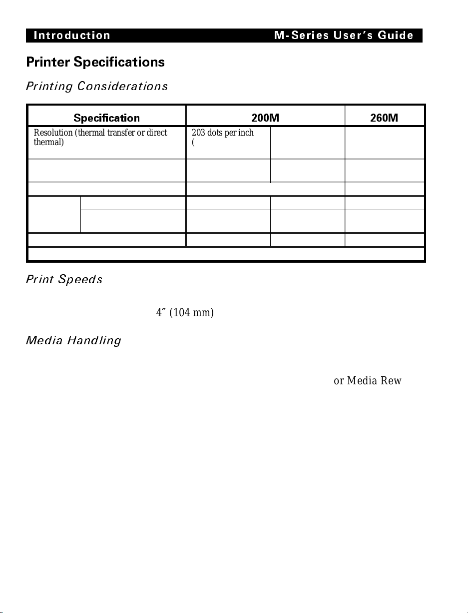
Printi ng Consi derat ions
Specification 200M 260M
Resolution (thermal transfer or direct
thermal)
Dot size 0.00492"
Maximum pr in t widt h 4.09" (104 mm ) 6.30" (160 mm)
Maximum
print length
Bar code m odulus (“X”) dimen si o n 5 mil to 55 mil 6.6 mil to 72 mil 5 mil to 55 mil
Thin film print he ad with Ene rg y Contro l
Standar d mem or y 15" (381 mm) 26" (660 mm ) 9.5" (241 mm )
With 512 KB additional
memory
Print S peeds
Programmable constant printing speeds of 2″ (51 mm),
3″ (76 mm), 4″ (104 mm), 5“ (127 mm), and 6″ (152 mm) per second.
203 dots pe r inc h
(8 dots per mm )
(0.125 mm )
39" (991 mm) 39" (991 mm) 25" (635 mm)
Optional 152 dot s
per inch ( 6 dot s
per mm )
0.00656"
(0.16 7 m m )
203 dots per inch
(8 dots per mm)
0.00492"
(0.125 mm)
Media Ha ndli ng
• Tear-off mode: Pr oduced in stri ps.
• Peel-off mode: Requires Peel-Off option or Media Rewind
option. Labels are dispensed and peeled from the liner,
and the liner is rewound internally.
• Rewind mode: Requires Media Rewind Option. A full roll
of pri n te d la be ls a re r e wo und in te rn al ly.
1-6
Page 16
M-Series User s Guide Introduction
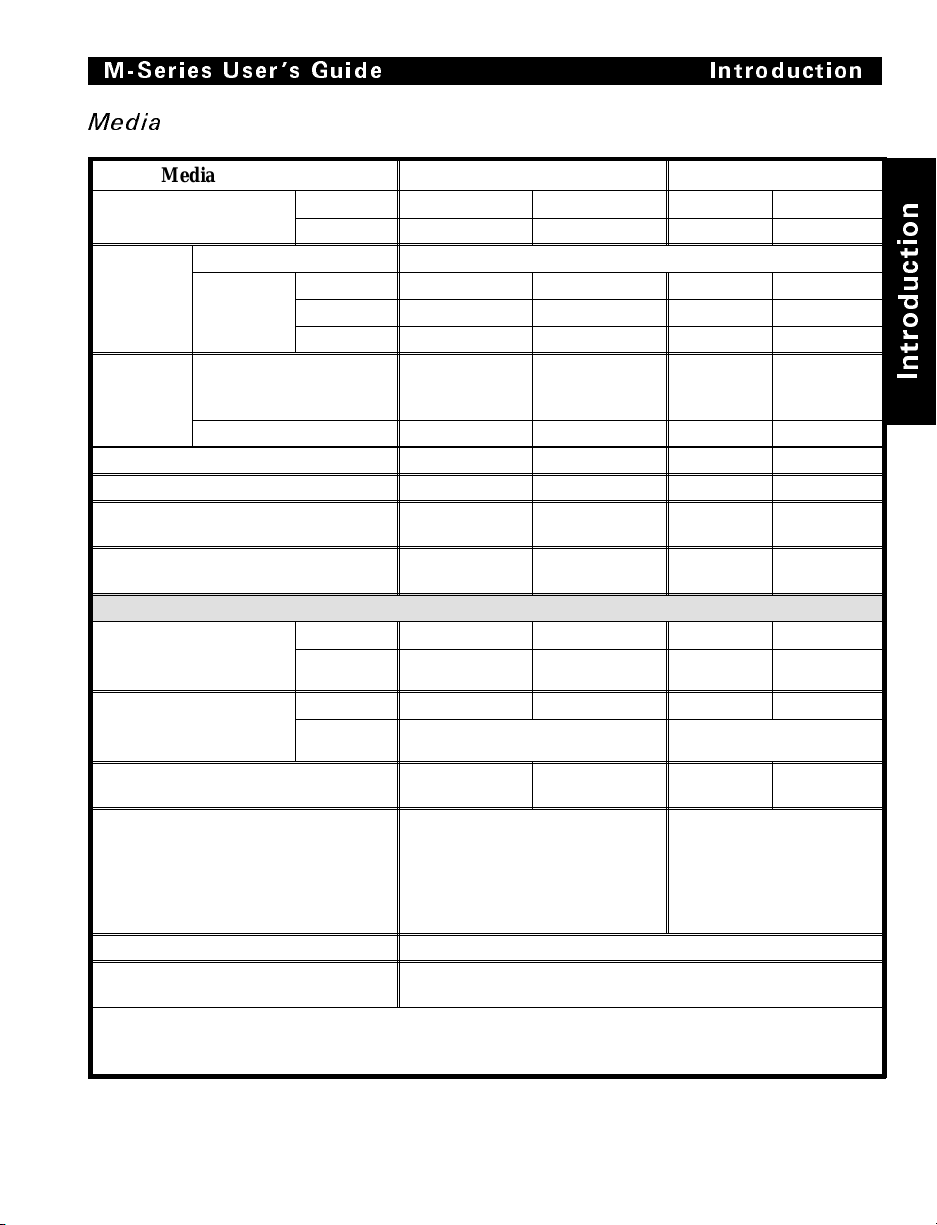
Media
Media Spe ci fi cation s 200M 260M
Total media width Maximum 4.5" 115 mm 7.2" 182.9 mm
Minimum 0.75" 19 mm 2.0" 50.8 mm
Label
length
Total
thic kn e ss
(includes
liner)
Core size 3.0" 75 mm 3.0" 75 mm
Maxi m um ro ll di amet er 8.0" 203 mm 8.0" 203 m m
Interlabel gap
(0.115"/3 mm preferred)
Maximum internal fanfold media pack
size (L x W x H)
Additional Specificat i ons for Black-Mark Medi a*
Mark thickness
(mea suring parallel to
label/tag edge)
Mark width (measuring
perpendi cu la r to
label/tag edge)
Mark -t o- m ar k leading edg e re gi st rati on
tole ra n c e
Mark location Mark is recommended to be
Mark density > 1.0 ODU (Optical Dens ity Unit )
Density of the back of the medi a on
which the black mark is printed
* The 200M ca n be f ie l d-e qui pped wit h an op ti onal refl ec t iv e (b la ck -m a rk) m edi a sen sor which repl a ce s
the factory- inst al led trans m iss iv e sens or. The blac k-m a rk medi a specificat io ns shown f or the 200M re quire
that the optional reflective sensor kit be installed.
Maximum Refer to “Printing Cons ider ati ons ” on page 1-6.
Minim um Tear-Off 0.5" 12.8 mm 0.63" 16. 00 m m
Peel- Off 0.5" 12. 8 mm 0.75" 1 9. 05 m m
Rewi nd 0.5" 12.8 mm 0.75" 19. 05 m m
Maximum (P rinthead
position m a y nee d to be
adjusted a bove 0.01" )
Minimum 0.0023" 0.058 mm 0.0023" 0.058 mm
Minimum 0.12" 3 mm 0.12" 3 mm
Maximum 0.43" 11 mm 0.43" 11 mm
Minimum 0.43" 11 mm 0.43" 11 mm
Maximum Full media width. Full media width.
0.012" 0.304 mm 0.012" 0.304 mm
0.079" - 0.157" 2 - 4 mm 0.079" -
8.0" x 4.5" x
6.2"
+ /- 0.016" +/- 0.4 mm +/- 0.016" +/- 0.4 mm
located on the inside of the media
(closest to the printer’s mainframe
when loaded in the printer). If
mark is located elsewher e, tes t for
your application.
0.5 ODU maximum
203 x 105 x
158 mm
0.157"
8.00" x
7.2 " x 6.2"
Marks m ust be located on
the insi de of the me di a
(clo sest to th e printer’ s
mainframe when loaded in
the printer) .
2 - 4 mm
203 x 183 x
158 mm
n
o
i
t
c
u
d
o
r
t
n
I
1-7
Page 17

Introduction M-Series User s Guide
Ribbon
Ribbon Widt h
Brady recommends using ribbon at least
as wide as the media you are using to
protect t he printhea d from w ear.
Standard
Lengths
Roll s iz e Inner diamet e r of core 1.0" 25.6 m m 1.0" 25.6 mm
2:1 media to ribbon r ol l rati o 984 ft 300 m 984 ft 300 m
3:1 media to ribbon r ol l rati o 1476 ft 450 m 1476 ft 450 m
Outside diameter of full roll of ribbon 3.2" 81 mm 3.2" 81 mm
Maximum 4.33" 110 mm 6.85" 174 mm
Mini m um 0. 95" 24 mm 2.0" 50.8 mm
200M 260M
Zebra Programm ing Lan guage II (ZPL II®)
° Downloadable graphics with data compres-
sion
° Bit image data transfer and printing, includ-
ing mixi ng of t ext a nd gr aph ics
° Format inversion
° Mirror image printing
° Four-position field rotatio n
(0°, 90°, 180°, 270°)
° Bitmap and s calab le font s
° Programmable quantity with print pause
° Communic ates in pr intab le ASCI I cha rac-
ters
° Controlled by a mainframe, minicomputer,
PC, or o the r da ta en try d ev ice
° Seriali zed fiel ds
° In-Spec OCR-A and OCR-B
° UPC/EAN [nominal 100% magnification
(6 dots/mm only)]
Bar C odes
° Code 11, Code 49, Code 93
° Code 39 (S up port s ra ti os of 2: 1, 3 :1, 5 :2,
7:3)
° Code 128 (Supports serialization in subsets
B and C and UCC Case C Codes)
° CODABAR (Sup po rts R ati os of 2: 1, 3:1 ,
and 5:2)
° Interleaved 2 of 5 (Supports Ratios of 2:1,
3:1, and 5:2; also su ppor ts Modul us 10
Check Digit )
° Indu str ial 2 of 5, S tand ard 2 of 5
° Ples sey
° CODABLOCK
° MAXICODE
° UPC-A, UPC-E, UPC EXTENSIONS
° PDF 417
° POST NET
° Check-digit calculation where applicable
° MSI
° EAN-8, EAN-13, EAN EXTENSIONS
° LOGMARS
1-8
Page 18
M-Series User s Guide Introduction
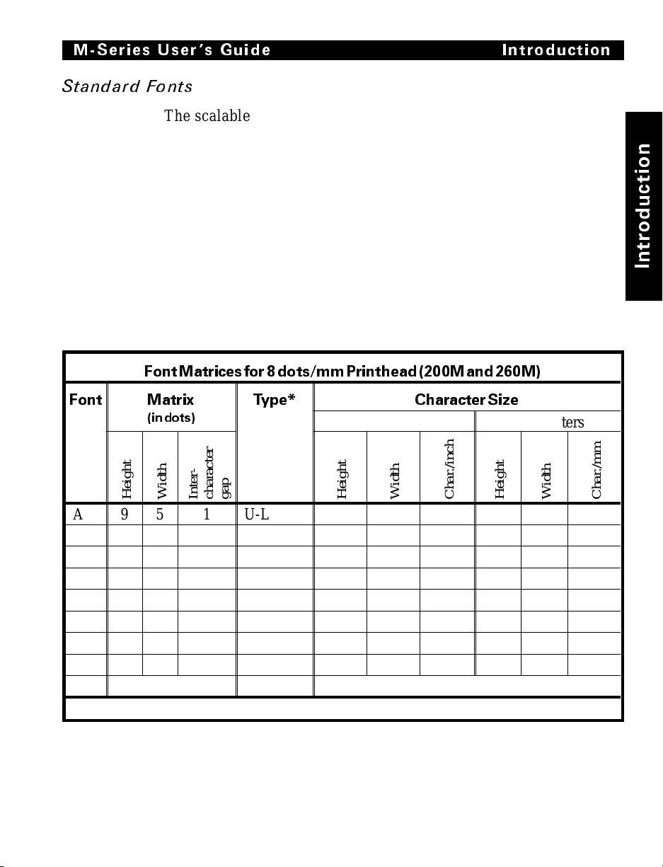
Standard Fonts
The scalable smooth font (CG Triumvirate Bold Condensed) is
expandable on a dot-by-dot basis, height- and width-independent,
while maintaining smooth edges. Maximum size depends on
available m emory.
Fonts A, B, C, D, E, F, G, H, and GS are expandable up to 10
times, height- and width-independent; however, fonts E and H
(OCR-A and OCR -B) ar e not consid ered in -spec when expand ed.
IBM Code Pag e 850 int ernati onal characte r sets are av ailab le in
fonts A , B, C , D, E , F, G, and Ø t hrough s oftware contro l.
Note: See the Op tion s Sectio n for the a va ilability of additional
fonts.
FontMatricesfor8dots/mmPrinthead(200Mand 260M)
n
o
i
t
c
u
d
o
r
t
n
I
Font Matrix
(indots)
Height
Width
Inter-
A 9 5 1 U-L-D 0.044 0.029 33.90 1.13 0 .75 1.33
B 11 7 2 U 0.054 0.044 22.60 1.38 1.13 0.89
C, D 18 10 2 U-L-D 0.088 0.059 16.95 2.25 1.50 0.67
E 28 15 5 OCR-B 0.138 0.098 10.17 3.50 2.50 0.40
F 26 13 3 U-L-D 0.128 0.079 12.71 3.25 2.00 0.50
G 60 40 8 U-L-D 0.295 0.236 4.24 7.50 6.00 0.17
H 21 13 6 OCR-A 0.103 0.093 10.71 2.63 2.38 0.42
GS 24 24 0 SYMBOL 0.118 0.118 8.48 3.00 3.00 0.33
Ø Default: 15 X 12 U-L-D Scalable
* U = Uppercase, L = Lowercase, D = Descenders
Type* CharacterSize
Inches Millimeters
character
gap
Height
Width
Char./inch
Height
Width
Char./mm
1-9
Page 19
Introduction M-Series User s G uide
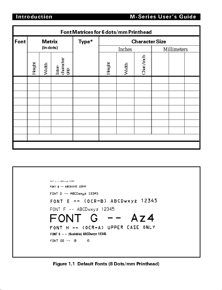
FontMatricesfor6dots/mmPrinthead
Font Matrix
(indots)
Height
Width
Inter-
character
Type* CharacterSize
Inches Millimeters
gap
Height
Width
Char./inch
Height
Width
A 9 5 1 U-L-D 0.059 0.039 25.40 1.50 1.00 1.00
B 11 7 2 U 0.072 0.059 16.93 1.83 1.50 0.67
C, D 18 10 2 U-L-D 0.118 0.079 12.70 3.00 2.00 0.50
E 21 10 3 OCR-B 0.138 0.085 11.72 3.50 2.17 0.46
F 26 13 3 U-L-D 0.171 0.105 9.53 4.33 2.67 0.38
G 60 40 8 U-L-D 0.394 0.315 3.18 10.00 8.00 0.13
H 17 11 4 OCR-A 0.112 0.098 10.16 2.83 2.50 0.40
GS 24 24 0 SYMBOL 0.157 0.157 6.35 4.00 4.00 0.25
Ø Default: 15 X 12 U-L-D Scalable
* U = Uppercase, L = Lowercase, D = Descenders
Standard P rinter Font Examples
Char./mm
Figure 1.1 Default Fonts (8 Dots/mm Printhead)
1-10
Page 20
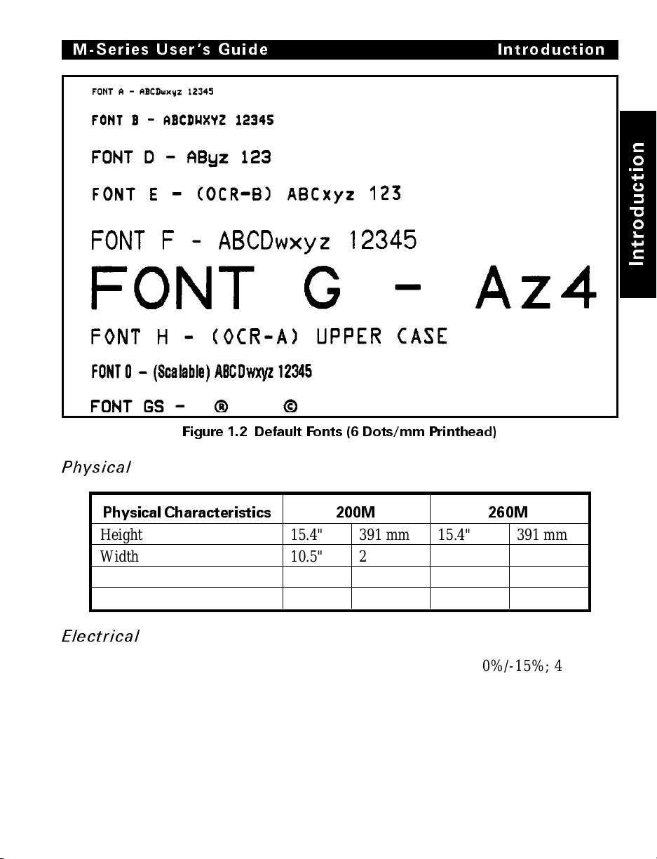
M-Series User s Guide Introduction
Figure 1.2 Default Fonts (6 Dots/mm Printhead)
n
o
i
t
c
u
d
o
r
t
n
I
Physica l
PhysicalCharacteristics 200M 260M
Height 15.4" 391 mm 15.4" 391 mm
Width 10.5" 267 mm 13.1" 333 mm
Depth 18.9" 480 mm 18.9" 480 mm
Weight (option-dependent) 43 lbs. 19.5 kg 55 lbs. 2 4.9 kg
Electrical
100-120 VAC +10%/-15% or 220-240 VAC +10%/-15%; 48-62 Hz
5 Amps @ 115V, 3 Amps @ 230V
UL 1950 Listed-Certified to CAN/CSA-C22.2 No. 950- M89;
Classified to IEC 950; complies with FCC and Canadian DOC
class “A” rules
Carries the C E mark of c ompliance .
1-11
Page 21
Introduction M-Series User s Guide
Communi cat ions Int erfac e
• RS-232 at 110 to 19,200 baud (select from standard rates).
Baud rate, data bits, parity, error detection protocol, and
XON-XOFF or DTR/DSR handshaking are all switchselectabl e.
• 200M: Centronics
ity Mode Parallel Interface. Maximum cable length: 10 ft.
(304.8 cm)
®
paralle l int erface. 260M : Co mpati bil-
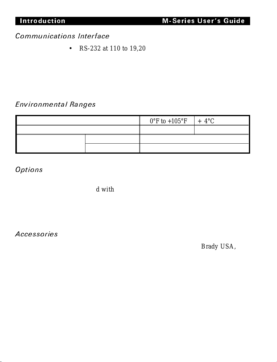
Environ mental Ranges
Operating temperature +40°F to +105°F + 4°C to +41°C
Storage temperature −40°F to +158°F −40°C to +70°C
Non-condensing
relative humidity
Operating 20% to 85%
Storage 5% to 85%
Options
6-dots/mm printhead (200M only)
Media Rewind with rewind and peel-off capabilities
Peel-Off cap abil ity only
Additional 512 KB memory
256 KB non-volatile memory (200M only)
Scalable and bit-mapped smooth fonts
Accessories
A Printer Cleaning Kit (PCK-2) is available from Brady USA, Inc.
1-12
Page 22
Unpacking
When unpacking the Brady M-Series Printer, make sure you save
all packing materials. Once the printer is out of the box, raise the
printer’s Media Access Door and remove the power cord.
Inspection
Inspect th e printe r for possibl e damage i ncurre d durin g shipme nt.
• Check all ext erior s urfaces for damage.
• Raise the Me dia Acces s Door and in spect compartm ent for
damage to components.
Reporting Damage
If you discover shipping damage upon inspection:
1. Immediately notify the shipping company of the damage.
2. Retain all packaging material for shipping company inspection.
3. File a damage report with the shipping company and no tify
your local distributo r and Brady USA, Inc. of the damage.
Brady USA, Inc. is not resp onsi ble for any damag e incu rred
during shipm en t of the equipmen t and will no t repair this
damage under warranty. Immediate notification of damage to
the shipping com pany or its in suring agency will generally
result in ensuring any damage claim validity and ultim ate
monetary compensation .
Installation
n
o
i
t
a
l
l
a
t
s
n
I
Storage and Reshipping
If you are not placing the printer into operation immediately,
repackage it using the original packing materials. The M-Series
Printer may be stored under the following conditions.
• Temperature: -40° to +158° F (-40° to +70° C)
• Relative humidity: 5% to 85% non-condensing
2-1
Page 23
Installation M-Series Users Guide
Should it become necessary to ship your printer, remove any
ribbon and pape r roll from the supply spools, otherwise damage
to the printer could result. Carefully pack the printer in a suitable
container to avoid damage during transit. Whenever possible, use
the original container and packaging material from the factory. If
you use a different container, a procedure similar to the original
fac tor y pa ck ag in g s h oul d be fo l low e d.
CAUTION: Do not package the printer in a rigid container
without utilizing shock mounts or shock-absorbing packing
material. A rigid container will allow shock on the outside to
be transmitted undampe d to the unit, which ma y caus e dama ge .
Power Connection
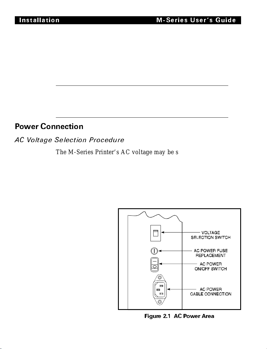
AC Voltage Selection Procedure
The M-Series Printer’s AC voltage may be set for either
100-120 VAC or 220-240 VAC operation. To match the printer’s
power entry s elec tion to the avai lable power s ource, r efer to
Figure 2.1 and follow the procedure outlined below:
1. Locate the AC p ower area at the re ar of the printer.
2-2
2. Using a small flatblade screwdriver or similar tool, move the
Voltage Selection switch to the 100-120 V or 220-240 V position as required. (The initial position of
the switch depends on how
the printer was
ordered.) Make
sure that t he appropriate fuse
is in place. See
Fig. 2.1.
Figure 2.1 AC Power Area
Page 24

M-Series User s Guide Installation
AC Power Fuse Replacement
A user-repl aceable AC Po wer Fuse is loca ted just ab ove t he
Power ON/OFF Switch. (See Figure 2.1.) For a 100-120 VAC
inst a llat ion, th e replacement fuse is a 3AG Fast Blow style rated at
5 Amp/250VAC. For a 220-240 VAC installation, the fuse is the
sam e s tyl e bu t ra te d at 3 Amp/250VAC. Make sure the fuse you
use is correct for the voltage source.
Before replacing the fuse, turn the AC Power Switch OFF and
unplug the AC Power Cable.
To replace th e fuse, insert t he ti p of a flat b lade screwdri ver into
the slot in the end of the Fuse Holder End Cap. Press in slightly
on the End Cap and turn the screwdriver slightly
counter-clockwise. This will disengage the End Cap from the
Fuse Holder and allow you to remove the fuse. To install a new
fuse, reverse the proced ure.
100-120 VAC Operati on
1. Confirm that the voltage selector switch is set to 120 V.
2. Attach the suppl ied power co rd to t he AC p ower recep tacle l o-
cated on the rear of the printer.
n
o
i
t
a
l
l
a
t
s
n
I
3. Connect the opposite end of the power cord to a properly
grounded source of 100-120 VAC (50 or 60 Hz) power rated
for at leas t 5 Amps.
220-240 VAC Operati on
1. Confirm that the voltage selector switch is set to 240 V.
2. Depending on how the printer was ordered, a power cord may
or may not be provided for 220-240 VAC operation. If not provided, obtain a cord set with the proper AC Power plug. The
cord may th en be con nected to t he sta ndar d (inter natio nal)
IEC-type 3-prong AC connector provided on the M-Series
Printer. Refer to Appendix A for more information.
2-3
Page 25
Installation M-Series U sers Guide
Site Requirements
CAUTION: To ensure that the M-Series Printer has proper
ventilation and cooling, do not place any padding or cushioning
material on the back of or underneath the unit because this will
restrict t he air flow .
The M-Series Printer may be installed on any solid, level surface
of sufficient size and strength to accommodate the unit. The area in
which the printer will operate must meet the e nvironmental
conditions specifie d .
Since the Brady M-Series Printer was designed and is fabricated
as an industrial-type unit, it will function satisfactorily i n ar e as
such as a warehouse or factory floor that conform to the specified
environmental and el ectrica l co ndition s.
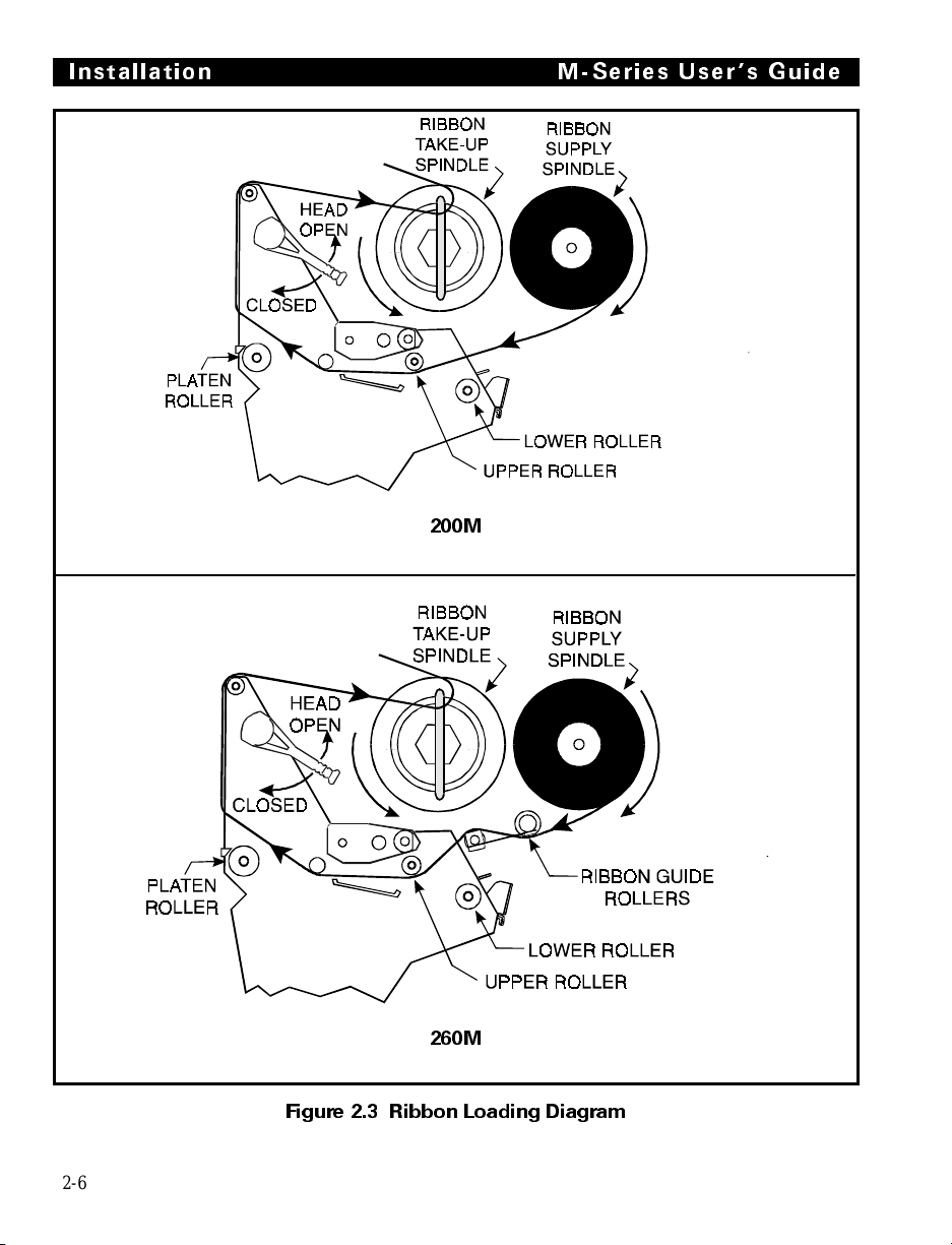
Ribbon Loading
Refer to Figure 2.3 throughout this procedure.
Note: When placing the ribbon roll on the Ribbon Supply Spindle,
make sure that the core is pushed up against the stop on the
ribbon supply spindle and that th e ribbon is aligne d
squarely with its core. If this is not don e, the ribbo n may
not cover the inside edge of the printhead, exposin g print
elements to potentially damaging cont act wit h the media.
2-4
Note:
CAUTION: Do not use ribbon that is narrower than the media. If
the printhead is not protected by the smooth backing of the ribbon,
excessive abrasion may cause premature printhead failure.
Do not load ribbon if the printer is to be used in the Direct
Thermal Mode.
Page 26

M-Series User s Guide Installation
1. Align the segments of the Ribbon Supply Spindle. See Fig-
ure 2.2. The Ribbon Supply Spindle is actually made up of
either two or three segments that rotate independently. Each
segment has a Spring Plate on it. It is important that these
Spring Plates be in alignment prior to installing the ribbon
roll on the spindle.
2. Place the Ribbon Roll on the Ribbon Supply Spindle.
3. Open the printhead by moving the handle to the OPEN posi-
tion.
4. Impo rtan t. .... To make ribbon loading and unloading easier,
make a leader for your ribbon roll if it doesn’t already have
one:
Tear off a strip of media (labels and backing) about 6 to 12 inches long
from the roll . Peel o ff a lab el fr om th is str ip. Re move the re maini ng l abels. Apply h alf of th is la bel to the end o f the s tri p and the ot her half to
the end of the ribbon. This acts as a ribbon leader.
5. Thread the leader and attached ribbon as shown in the illustra-
tion. Be careful not to crease or wrinkle the ribbon.
6. Remove the Hook from the Ribbon Take-Up Spindle.
7. Place the leader under the long leg of the Hook and wind several
turns.
n
o
i
t
a
l
l
a
t
s
n
I
8. Close the printhead by moving the lever to the CLOSED posi-
tion.
Align the blades on the Ribbon
Supply Spindle before loading
the ribbon roll.
Figure 2.2 Ribbon Supply Spindle Alignment
2-5
Page 27
Installation M-Series U sers G uide
200M
2-6
260M
Figure 2.3 Ribbon Loading Diagram
Page 28

M-Series User s Guide Installation
Media Loading
To load media, move th e Pri nthea d Locking Lever to the OP EN
position. Refer to Figures 2.4, 2.5, and 2.6. When the media is
loaded, close the printhead by moving the lev er on th e up per
printh ead mechani sm to th e CLOS ED position.
Note: The first time you load media and whenever you
subsequently change the med ia type you must r e -calibrate
the printer. See the Configuration and Cali b ration S ection.
Permasleev e Pri nt in g
For information about Permasleeve Printing, refer to Appendix F.
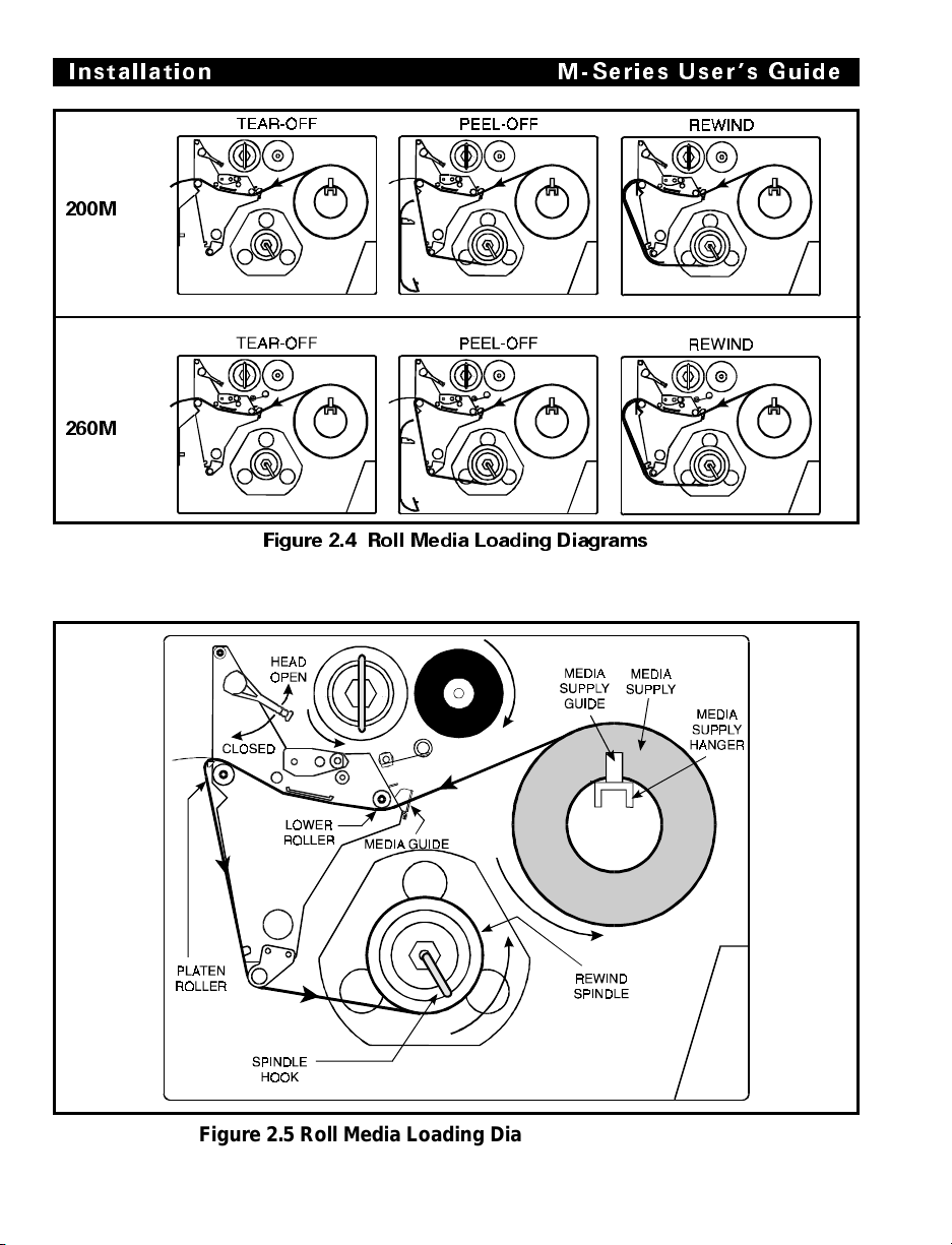
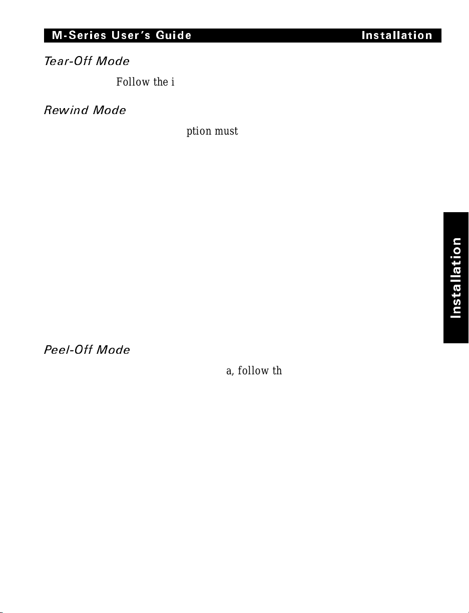
Roll Media
Roll media may contain labels of a fixed length with gaps
in-between or it may be formed as one continuous length with no
gaps (see Continuous Media.) Both types of roll media mount
inside the printer in the same manner. To load roll media, refer to
Figure 2.4 and/or 2.5 and do the following.
1. Move the Media Guide and Media Supply Guide as far away
from the printer frame as possible.
2. Place the med ia rol l on the Media S upply Hanger.
3. Push the Media Supply Guide inward until it is just touching
the outer side of the Media Supply Roll, then lock the guide in
place with i ts lock ing sc rew. (T he Guide must n ot cause pressure or excessive dr ag on the Media Supply Rol l.)
4. Thread the media through the printhead as shown in the illus-
trations.
5. Adjust the Med ia Guide and Medi a Suppl y Guide until they
just touch the outer edge of the media without causing it to
buckle.
6. Close the printhead by moving the lever located on the upper
printhea d asse mbly to the C LOSE D pos itio n.
n
o
i
t
a
l
l
a
t
s
n
I
2-7
Page 29
Installation M-Series U sers Guide
200M
260M
Figure 2.4 Roll Media Loading Diagrams
2-8
Figure 2.5 Roll Media Load i ng Diagram ( with Peel-O ff )
Page 30
M-Series User s Guide Installation
Tear-Off Mode
Follow the instructions described in Roll Media.
Rewind Mode
The Rewind Option must be installed in the printer. To initially
configure t he prin ter for this mode, fo llow t hese s teps:
1. Remove the Medi a Rewind P lat e from i ts sto rage locatio n in
front of the printhead inside the media compartment.
2. Invert the Rewi nd Pl ate so that the l ip on th e attach ed Hook
Plate points down.
3. Insert the Hook Plate lip a short distance (1/2") into the lower
opening in the Side Plate.
4. Align the upper end of the Rewind Plate with the correspond-
ing opening in the Side Plate and slide the Rewind Pl at e in s o
that it stops against the Main Frame.
5. Remove the Hook from the Take-Up Spindle Shaft.
6. Rou te th e m ed i a as s ho w n in F igu re s 2. 4 an d 2. 5, w ind i t 1 - 2
times aro und a 3" core .
n
o
i
t
a
l
l
a
t
s
n
I
Peel- Off Mode
After loading the media, follow these steps:
1. Remove the Rewind Plate if one is present and store it on the
2. Load media as shown in Figures 2.4 and 2.5.
3. Remove the Hook from the Take-Up Spindle Shaft.
4. Remove several labels from the media backing and then wind
two mounting screws on the inside of the front panel. Align
the notch or web in the media so that the Take Label Sensor
can sense a peeled label .
the backing 1-2 times around the Media Take-Up Spindle and
reins tal l the Hoo k.
2-9
Page 31

Installation M-Series U sers G uide
Fanfold Media
To load fanfold media, place the fanfold media in the bottom or
to the rear of the media compartment and thread it through the
printhead as shown in Figure 2.6. Adjust the media guide using
the thumb screw to keep the media from drifting left or right.
Fanfold media from outside the printer feeds through one of the
two access slots, one at the bottom of the printer and one at the
rear.
2-10
200M
260M
Figure 2.6 Fanfold Media Loading Diagrams
Page 32

M-Series User s Guide Installation
Removing Used Ribbon
To remove used ribbon, refer to Figure 2.7 and follow the steps
below.
1. Pull the hook out slightly, then rotate the hook back-and-forth
several times as shown and remove it from the spindle.
2. Grasp the used rib-
bon and remove it
from the Ribbon
Take-Up Spindle.
3. Remove the
empty core from
the Ribbon Supply Spindle.
4. Follow the Rib-
bon Loading procedu re o n pa ge
2-4 to load the
new ribbon.
Figure 2.7 Removing Used Ribbon
n
o
i
t
a
l
l
a
t
s
n
I
Initial Printer P ower Up
After you finish loading the ribbon and media, continue reading
through Sections 3 and 4. Perform the following initial printer
power-up steps as you come to them:
1. Power ON Self Test (POST)
2. Calibration
Subsequent power-ups will not necessarily require step 2 to be
performed. See Sections 3 and 4 for further information.
2-11
Page 33

Installation M-Series U sers G uide
2-12
Page 34

Operating Your Brady M-Series Printer
Now that your printer is ready for operation, how does it work?
The Brady M -Seri es Pr inter is des igne d to r eceive i ns tructi ons
from a host comput er, such as an IBM-c ompat ible P C. To creat e a
label, you will either need to use label design software or write a
format in ZPL II
label formats. If you are using label design software, refer to the
instructions provided with your software package to determine
how t o pr oc ee d.
If you are using, or plan to use, ZPL II, make sure you have a
copy of the ZPL II Programming Guide. This free guide was
available at the time you ordered your printer, but if you do not
have a copy then submit the mail- or fax-in card in the front of
this book to get a copy.
®
, which is a programming language for creating
Printer Operating Modes
The M-Series Pri nter can be co nfigured for several d iffe rent
modes of operation by sending the proper commands from the
host computer. For 260M printers, operating modes may also be
configured via a bank of DIP switches at the rear of the printer.
(See Chapter 4 for more information about DIP switches.)
Media Sensi ng Modes
There are two basic modes by which the printer can sense the
position of the media: Transmissive Sensing Mode and
Black-Mark Sensing Mode. The 260M comes standard with both
Transmissive Sensing Mode and Black-Mark Sensing Mode
capabilities. The 200M comes standard with Transmissive
Sensing Mode capability, but you may field-retrofit it for
Black-Mark Sensing by replacing the Transmissive Sensor with a
Black Mark Sensor.
Transmissive Sensing Mode
In Transmissive Sensing Mode, a sensor detects a light shining
through a web, notch, or hole in non-continuous media. In this
way, the printer determines the position of the label/tag.
Operation
n
o
i
t
a
r
e
p
O
3-1
Page 35

Operation M-Series User s Guide
Black-Mark Sensing Mode
In Black-Mark Sensing Mode, you use continuous media (no
notch or gap) having black marks printed on the back of the label
liner for each label . T o determi ne the l abel l engt h and top of
label, the pr int er’s Bl ack Mark S ensor detect s the black mark
similar to the way in which the Transmissive Sensor detects the
notch or gap in the media.
Media Transport Modes
Tear-Off Mode
When the media is in the rest (idle) position, the webbing
between labels is over the Tear-Off/Peel-Off Bar. To print a label,
the printe r first backfe eds the media u ntil t he st art of the label is
directly under the printhead and then prints the entire label.
After a label is printed, the media feeds forward until the end of
the label is past the Tear-Off/Peel-Off Bar. This label position is
determined by commands sent to the printer from the host
computer.
When a quanti ty of labels i s re quired, a format for printi ng a
batch of labels can be sent to the printer. Once a label is printed,
the media wi ll feed forwa rd to the star t of the nex t labe l and
printing will continue. In this way, the printer will print the batch
and stop when it reaches the quantity required.
When a quantity of individual labels is required, the format for
printing a batch of labels can still be sent to the printer. The
operator can use the PAUSE Key to cycle the printing one label at
a time. The oper ator can then tear off e ach lab el befo re p rinti ng
the next one.
Peel-Off Mode
When the med ia is in th e res t (idle) posi tion , the s tart of the la bel
to be printed is slightly in front of the printhead. To print a label,
the printe r first backfe eds the media u ntil t he st art of the label is
directly under the printhead and then prints the entire label.
In this mode, once the label is printed, the media passes over the
Tear-Off/Peel -Of f Bar a t an ext remel y shar p angle. The back ing
material is peeled away from the label and winds around the
Peel-Off Sp indle or t he Me dia Rewi nd Spi ndle. The m edia fee ds
forward until most of the label hangs loose from the backing. The
3-2
Page 36

M-Series User s Guide Operation
label is held in this position by that portion of the backing that
has not crossed the Tear-Off/ Peel-Off Bar .
The Label Available Sensor is located on the printer in a position
where it is activated by the label. When the operator removes the
label, the printer backfeeds the media either to the rest (idle)
position or to the printing position and prints the next label.
When it is necessary to remove the media backing from the
Take-Up Spindle, you do not need to turn the printer OFF.
Rewind Mode
Some applications call for the media to be rewound onto a core as
the labels are printed.
When the med ia is in th e res t (idle) posi tion , the s tart of the next
labe l i s d ir e ct l y unde r the pr in t h e ad . A fter the label is printed, the
media feeds forward until the start of the ne xt la bel is under the
printhead. The med ia nev er b ac kf ee ds i n th is mo de .
When the printer completes a batch of labels, printing will stop.
Front P anel Keys
PAUSE Key
The PA USE key st ops a nd res tar ts the pr inti ng pr oc ess.
If the printer is idle (not printing) when the PAUSE key is
pressed, no printing can occur. If the PAUSE key is pressed while
printing is in progress, the printing stops once the current label is
complete.
Pressing the PAUSE key a second time resumes the printing
process.
n
o
i
t
a
r
e
p
O
FEED Key
The FEED key forces the printer to feed one blank label. If the
printer is idle (not printing), or if the PAUSE function is active
when the FEED key is pressed, one blank label feeds from the
printer immediately. If the printer is printing, then one blank
label feeds out after completion of the current batch of labels.
After one blank label feeds out, pressing FEED again provides
anot he r b l ank la be l.
3-3
Page 37

Operation M-Series User s Guide
CANCEL Key
The CANCEL key is only
recognized in PAUSE m ode.
Press CANCE L to can cel the
current label format. If no
format is printing, then the next
one to be printed will be
canceled. If no fo rmats a re in
memory , the CAN CE L k ey i s
igno red.
If the CANCEL key is pressed
for an extended period of time
(3 seconds), the printer cancels
all formats in memory and the
DATA light turns OFF.
MODE Key
The MODE key puts the printer
in Configuration Mode. In this
mode, you can adjust the Print
Darkness, Media Tear-off
Position, and Label Top
Position, or perform a
Calibration. See Section 4.
Figure 3.1 Printer Front Panel
3-4
Page 38

M-Series User s Guide Op eration
Front Panel Lights
Refer to Figure 3.1 for the location of the lights.
Note: If an operating condition which causes a light to be ON
constantly and one which causes the same light to Flash
occur simultaneousl y, the light Flashes.
Light(LED)
Name
POWER ON Printer is ON.
PRINTHEAD OFF Normal operation.
PAPER/
RIBBON
PAUSE OFF Normal operation.
DATA OFF Normal operation, no data being received.
DARKEN ON Printer is in the Config uration M ode. See Section 4,
POSITION ON
CALIBRATE ON
Status Indication
ON Head Over Temperature condition. Printing stops until the
printhead cools down. Printing resumes au tom ati cally.
Printhead Und e r Temperature co ndition. Printing continues.
Power Supply Over Temperature condition. Printing stops
until the power supply cools do wn. Printing r esumes
automatically.
Flashing Printhead Open.
OFF Media and ribbon (if used) are properly loaded.
ON Paper out.
Flashing 1. In Thermal Transfer Mode: Ribbon is out.
2. In Direct Thermal Mode: Ribbon is in the printer.
ON Printer has stopped all printing op eratio ns.
ON Labels are printing.
Single
flash
Flashing Receiving data from host computer.
Slow
flashing
The CANCEL key was pressed and a format was
successfully deleted from the print queue.
Printer sent a “stop transmittin g” command to the host
computer.
Configuration and Calibration, for more information.
n
o
i
t
a
r
e
p
O
3-5
Page 39

Operation M-Series User s Guide
Power On Self Test
A Power ON Self Test (POST) is performed each time the printer is
turned ON. This test checks for proper initialization of various
electronic circuits and establishes starting par ameters as those stored
in the printer’s memory. During this test sequence, the front panel
lights will turn ON and OFF to ensure proper operation. At the end
of this self test, only the POWER light w ill r emain lit. If othe r lights
are also lit, refer to the Troubleshooting Se ction.
Printer Self Tests
Introduc tion
These self tests produce sample labels and provide specific
information that helps determine the operating conditions for the
printer.
Each self test is enabled by holding in a specific Front Panel key
or combination of keys while turning the Power Switch ON.
Keep th e ke y depr esse d unt il th e Fron t Pa nel L ight s turn ON.
When the Power On Self Test is completed, the selected self test
automatically starts.
Notes: When performing self tests, all data interface cables
connected to the rear of the printer must be removed.
When canceling a self test before its actual completion,
always turn the printer Power OFF and then back ON to
reset the printer.
When performing these self tests in the Peel-Off Mode, the
operator must remove the labels as they become available.
Unless specifically stated, all tests print in Tear-Off mode
in Tear-Off printers and in Peel-Off Mode for Peel and
Rewind printers.
If your media is not wide enough, the test labels will only
print out to the edge of the label. If your media is too short,
the test label will continue printin g on the next label.
3-6
Page 40

M-Series User s Guide Operation
CANCEL Key S elf Test
This self test prints a single label which contains a listing of the
printer’s current configuration parameters stored in Configuration
(EEP ROM) Me mor y. Pres s the CAN CEL key whil e turn ing th e
AC Power Switch ON. See Figure 3.2.
The configuration may be changed either temporarily (for specific
label formats or ribbon and label stock), or permanently (by saving
the new parameters in EEPROM Memory.) Saving new parameter s
occurs whenever a Pri nter
Cali brat io n proc ed ure is
performed. Re f e r t o the
procedure in Section 4,
Configuration and
Calibrat ion.
n
o
i
t
a
r
e
p
O
Figure 3.2 Cancel Key Test Sample Printout
3-7
Page 41

Operation M-Series User s Guide
PAUSE Key Self Test
This self test is actually comprised of four individual test
features.
1. The initial self test prints 15 labels at speed “A” (2" per second) then automatically PAUSES the printer. Each time the
PAUSE key is pressed, an additional 15 labels print out.
2. While the printer is PAUSED, pressing the CANCEL key once
alters the self test. Now each time the PAUSE key is pressed the
printer prints 15 labels a t spe ed “D” ( 6" pe r second).
3. While the printer is PAUSED, pressing the CANCEL key a second time alters the self test again. Now, each time the PAUSE
key is pressed the printer prints 50 labels at speed “A”.
4. While the printer is PAUSED, pressing the CANCEL key
once alter s the se lf t est a t hird time. Now, each t ime t he
PAUSE key is pr essed the pr inter pr ints 50 labels at speed “D”.
Note: On printers with either the rewind or peel option installed,
the Peel Mode is activated during the first half (steps 1–4)
of the PAUSE Key Self Test. On printers with a rewind
option, the rewind plate must be removed for proper
function of the peel sensors during the test. The first label
to print will say, “PEEL OPTION INSTALLED”. Each
label must be manually removed from the sensor path
before the next label will print. Steps 1–4 will then be
repeated in Rewind Mode.
Figure 3.3 Pause Key Test Sample Printout
3-8
Page 42

M-Series User s Guide Ope ration
This self test can be used to provide the test printouts required
when making adjustments to the printer’s mechanical assemblies.
See the sample printout in Figure 3.3.
FEED Key Test
The CANCEL Key Self Test should be performed before this self
test.
Information on the “Configuration” printout (CANCEL Key Self
Test) will be used with the results of this self test to determine
the best Darkness Setting for a specific media/ribbon
combination.
The FEED Key Self Test printout will print at various PLUS or
MINUS Darkness settings relative to the Darkness value shown
on the Configuration Label. This test
makes 7 printouts at speeds “ A” (2"
per second) and “ C” (4" per second).
Inspect th ese pri ntouts an d de t e rm in e
which one has the best darkness
settin g for the application.
The value on that printout is added to
(plus) or su btracted from (m inus) th e
“D arkness” value specified on the
Configuration printout.
The resulting numeric value (0 to 30)
is the best darkness value for that
specific media/ribbon combination.
The plus or minus value can be
entered by the operator while
performing a Label Darkness
Adjustment procedure. Enter the
PLUS value by pressing the UP
(FEED) key, or ent er the MINUS
value by pressing the DOWN
(CANCEL) key the appropriate
number of times.
n
o
i
t
a
r
e
p
O
Optionally, the Darkness value can be
programmed into the ZPL II formats
Figure 3.4 Feed Key Test Sample Printout
3-9
sent to the printer.
Page 43

Operation M-Series User s Guide
FEED Key a nd PAUSE Key
Pressing these two keys at the same time, while turning the Power
ON, temporarily resets the Printer Configuration to the factory
default values. These values will be active until Power is turned
OFF. When ever th e printer is reset to facto ry defaults, a Med ia
Calibra tion procedure
must be perfo rmed immediately.
MODE Key Test
This test places the printer in the Communications Diagnostics
Mode. In this m ode, t he pri nter pri nts t he ASCI I char acters and
their corresponding hexadecimal val ues for any data r eceived
from the host computer. A typical printout from this test is shown
in Figur e 3.5.
Note: This label will be inverted when printed. )
Figure 3.5 Results of Communications Diagnostic Test
PAUSE Key and CANC EL Key Test
This test prints a maximum of 500 Head Test labels. Each label
backfeeds prior to printing and feeds forward to the rest position
after printing. A serialized number prints on each label. Press the
PAUSE key or turn the printer power OFF to stop printing. The
labels look like the one in Figure 3.3 except that a serialized
number will print on each label.
3-10
Page 44

M-Series User s Guide Opera tion
FEED Key a nd CANCE L Key Test
This test prints seven pre-programmed label formats at different
speeds. The pri nt er automa ticall y paus es after eac h forma t. The
sequence of label formats is as follows.
Label Format Qty Speed
Left Ribbon Wrinkle Test 20 D
Right Ribbon Wrinkle Test 20 D
C39 Wrinkle Test 20 D
Left Ribbon Wrinkle Test 20 A
Right Ribbon Wrinkle Test 20 A
C39 Wrinkle Test 20 A
Usable Area Test 10 D
Extended Printer Diagnostics
Extended diagnostic tests are available. The maintenance manual
provides the information needed to perform these additional tests.
Battery Replacement
One of the factory-installed options for the 200M is the Battery
Backed-up 256 KB Non-volatile SRAM Memory. The battery
used with this option is a 3 VDC lithium battery.
It is reco mmended that a qualifi ed ser vice t echnic ian repl ace this
battery since it requires internal access to the electronics area of
the printer. Further information regarding the replacement of this
battery is contained in the Maintenance Manual, Vol. 1: General
Maintenance.
(200M Only)
Label Format Qty Speed
Head Temperature Test 10 D
Upper Smear Test 10 D
Lower Smear Test 10 D
Usable Area Test 10 A
Head Temperature Test 10 A
Upper Smear Test 10 A
Lower Smear Test 10 A
n
o
i
t
a
r
e
p
O
CAUTION: Danger of explosion if battery is incorrectly
replaced. Replace only with the same or equivalent type
recommended by the manufacturer. Discard used batteries
according to the ma nufact urer’s i nstr uctions.
3-11
Page 45

Operation M-Series User s Guide
3-12
Page 46

Option Switches
These switches are located at the
rear of the printer above the Si gnal
Interface Cable C onnec tion. S ee
Figu re 4. 2.
In the tables on the following
page, an “R” means the switch is
OFF (positioned to the right),
while an “ L” means the switch is
ON (positioned to the left). All
switches are in the OFF positio n
when the printer is shipped from
the factor y.
Configuration and Calibration
Figure 4.1 Option Switches
n
o
i
t
a
r
b
i
l
a
C
d
n
a
n
o
i
t
a
r
u
g
i
f
n
o
C
200M 260M
Figure 4.2 Location of Option Switches
4-1
Page 47

Configuration an d Calibra tion M-Series U ser s Guide
Bank 1
(For Serial-Interface Printers O nly)
The M-Seri es P rinter , wit h the RS-232 S erial I nterface , us es eig ht
miniature switches located on the rear of the printer, above the
Signal Interf ace Cable C onnec tor. Th e ON/OFF p ositions of these
switches establish some of the Printer Configuration Parameters.
Bank 1 switches must be
properly positioned to
establish serial data
communications with the host
computer. Th ereaft er, the
position of these switches
shou ld n ot be c ha nge d.
Note: Parallel-interface
printers do not require
these configuration
parameters, therefore
they have no Bank 1
switches.
If these switches are in the
proper position to match the
communication configuration
of the host computer, and the
printer is not r eceivi ng data,
refer to the I nterc onne cti ons
Section and make sure the
correct in terfac e cable is
bein g use d.
Note: The printer is fixed at
1 stop bit, so m ak e su re
that your host device is
also set at 1 stop bit.
Bank1
(Serial-Interface Printers Only)
Switch
3 2 1
R R R 9600 baud
R R L 19200 baud
R L R 110 baud
R L L 300 baud
L R R 600 baud
L R L 1200 baud
L L R 2400 baud
L L L 4800 baud
Switch
4
R7 Data bits
L8 Data bits
Switch
6 5
R R Even parity
R L Parity di s a ble d
L R Odd parity
L L Parity disabled
Switch
7
R XON/XOFF control
L DTR/DSR control
Switch
8
R No erro r dete cti on
L Error detec tion active
(If you choose 7 data bits, you must
choose either even or odd parity.)
Baud Rate
Data Bits
(
Must be set to 8 Data Bits
to use Code Page 850.)
Parity
Communication
Handshake Contr ol
Error Detection Protocol
T a bl e 4.1
4-2
Page 48

M-Seri es Use r s Gui de Configuratio n and Ca libra tion
Bank 2
Switch
3 2 1
R R L Reserved
R L L Tear-Off
L R L Peel-Off
L L L Rewind
- - R Override is disabled
Switch
6 5 4
R R L Black-mark sensing mode
R L L Transmissive sensi ng mo de
L L L Transmissive sensing mod e
- - R Override is disabled
Switch
R L Thermal transfer
L L Direct thermal
- R Override is disabled
(260M Printers Only)
These swit ches can manu ally ov errid e any ZPL I I com mands t hat
affect print mode, media mode, and media type. They can also
override settings established during the calibration procedure.
Reasons why would might want to use these override switches:
Bank2
8 7
(260M Printers Only)
Print Mode
Media Mode
with non-contin uous media
(detects a web/notch)
with continuous media
Media Type
Tab le 4.2
• Troubleshooting. By using these
switches, you know beyond a doubt
what operating mode your printer is in.
• Lets you use a single ZPL II label for-
mat for many different printers—without worrying if t he form at conta ins a
mode command that is inappropriate
for your printer configuration.
• Some t hir d-par ty la be l de sig n s of tw a re
packages work bet ter i f thes e swi tches
control the mode.
If you do not want to override ZPL II or
the calibration settings, disable one or
more of the override options by setting
switches 1, 4, and/or 7 to the R (OFF)
position and turning the power ON. With
these disabled, the 260M will require
ZPL II commands and/or re-calibration to
set print mode, media mode, and/or media
type.
To override, set the switches to one of the
modes shown in the table. If you are in the
process of printing, this change takes
effect on the next label printed. If you
change the switches from active to
disabled after printer power-up, the printer
remains in the current mode until a ZPL II
command or re-calibration changes the
mode.
n
o
i
t
a
r
b
i
l
a
C
d
n
a
n
o
i
t
a
r
u
g
i
f
n
o
C
4-3
Page 49

Configuration an d Calibratio n M-Series User s Guide
Configuration Mode
The Configuration Mode allows you to fine-tune the internal
printer configuration settings for your application. In this mode,
you can change the following parameters:
• Print in g dar kne ss
• Rest position of the media with respect to the “web” or
“interlabel gap”
• Position of printing relative to the top of the label
• Media and Ribbon Sensor values
• Label length
• Printing method
• Media type (continuous or non-continuous)
You can get a printout of the printer configuration (the values for
each of these parameters) at any time by performing the CANCEL
Key Self Te st ( See Ch apter 3).
If it is ever necessary to reset the printer configuration to the
factory defaults, refer to the “FEED Key and PAUSE Key” Self
Test description in Chapter 7.
The ZPL II Programming Guide contains information on
instructions which may be sent to the printer to disable the
MODE key and set specific label format values for each of these
parameters. If you are not using ZPL II, refer to the instructions
provided with your software package to determine if you also
have this capability.
Calibration
IMPORTANT: Perform the Calibration Procedure when media and
ribbon are first installed and each time a different type of
media or ribbon is installed.
During this procedure, the printer automatically determines the
media type, label length, media and ribbon sensor settings, and
printing method. Media type is determined by sensing either
continuous or non-continuous media as blank labels move through
4-4
Page 50

M-Seri es Users Guide Configura tion a nd Ca librat ion
the printer. If non-continuous media is sensed, Label Length is
also calibrated. If ribbon is sensed, the Thermal Transfer Print
Method is configured. If no ribbon is present, the Direct Thermal
Print Method is configured.
The results of this calibration are stored in the printer’s memory.
These par a me te rs w i ll r ema in in ef f ect un til t he n ex t c a lib rat i on is
performed. The Printer Configuration Printout, which prints when
the CANCEL Key Self Test is performed, lists these results as
well as other printer parameters.
Note: If the printe r is in the Peel-Off Mode, the operator must
“catch” the labels as they are peeled away from the
backing duri ng thi s procedure.
1. Load media and ribbon (if used). Make sure the Media Sensor
is properly positioned (see Chapter 7 “Adjustments”).
IMPORTANT: To use a 260M in Black-Mark Sensing Mode,
make sure you set the Bank 2 DIP switches appropriately
(see page 4-3).
2. Turn the power s wit ch ON. When t he Po wer ON Sel f T est is
complete, the POWER, PAUSE, and PAPER/RIBBON lights
will be ON.
n
o
i
t
a
r
b
i
l
a
C
d
n
a
n
o
i
t
a
r
u
g
i
f
n
o
C
3. Press the MODE key 3 times briefly. PAUSE and CALIBRATE lights turn ON.
4. Press UP (FEED Key) to calibrate. The printer feeds some media. The MODE l ights will flash ON and OFF to i ndicate that
the settings have been saved in memory.
5. Press PAUSE to exit PAUSE mode. PAUSE light turns OFF.
4-5
Page 51

Configuration an d Calibration M-Se ries User s Guide
Adjust the Print Da rkness
This procedure sets the darkness of the printing on the label. Use
the lowest setting which provides the necessary print quality.
1. Press the MODE key. PAUSE and DARKEN lights turn ON.
2. Press UP or DOWN to adj ust t he curr ent se tting.
3. Press the MODE key 3 times. The MODE lights will flash ON
and OFF to indicate that the settings have been saved in memory.
4. Press PAUSE to exit PAUSE mode. PAUSE light turns OFF.
Adjust the Media Rest Posit ion
This procedure sets the end-of-label position relative to the
Tear-Off Bar o r Cutter .
1. Press the MODE key twice briefly. PAUSE and POSITION
lights turn ON.
2. Press UP or DOWN to adj ust t he curr ent se tting.
3. Press the MODE key twice briefly. The MODE lights will
flash ON and OFF to indicate that the settings have been
saved in memory.
4. Press PAUSE to exit PAUSE mode. PAUSE light turns OFF.
Adjust the Position o f the Top of t he Label
This procedure positions the printing on the label relative to the
top edge of the label.
1. Press the MODE twice briefly then press and hold for about 5
seconds until the lights change. PAUSE and DARKEN and
CALIBRATE lights turn ON.
2. Press UP or DOWN to adj ust t he curr ent se tting.
3. Press the MODE key twice briefly. The MODE lights will
flash ON and OFF to indicate that the settings have been
saved in memory.
Press PAUSE to exit PAUSE mode. PAUSE l ight turns OFF.
4-6
Page 52

System Components
Interconnections
BRADY PRINTER
Figure 5.1 System Components
System Considerations
Communi cat ions Co de
The Brady M-Se ri es Pr inter sends and re cei ves Ameri can
Standard Code for Information Interchang e (ASCII). This c ode
consists of 128 characters (256 for Code Page 850) including
upper and lower case letters, punctuation marks, and various
control codes.
Interfac es
The method of interfacing the Brady M-Series Printer to a data
source depends on the communication options installed in the
printer. Depending on how the printer was ordered, the interface
is either an RS-232 serial data port or a parallel port.
HOST
I.E.: COMPUTER
s
n
o
i
t
c
e
n
n
o
c
r
e
t
n
I
5-1
Page 53

Interconnections M-Series User s Guide
Data Specifications
When communicating via the serial data port (RS-232), the baud
rate, number of data bits, and the parity are user-selectable (see
Section 4 for acceptable setting combinations). Parity only
ap p lies t o d a ta t ra n s m itt ed b y th e p r in ter , since it ignores the parity
of received data. T he M -S er i e s P ri n te r i s fi xe d at 1 s t op bit, s o
make sure that your host is also set at 1 stop bit.
When communicating via the parallel port, the previously
mentioned parameters are not considered.
RS-232 Serial Data Port
The connections for the standard interface are made through the
DB25S connector on the rear panel. For all RS-232 input and output
signals, the M-Series Printer follows both the Electronics Industries
Asso ci ation’s (EIA) RS-232 and the C on sult ati ve Com m ittee fo r
International Telegra p h a n d Te l ep hone (CCITT) V.24 standard
signal level speci fica tions.
PinNo. Description
1
2
3
4
6
7
20
Frame Ground for Cable Shield
TXD (Transmit Data) output from the printer
RXD (Receive Data) input to the printer
RTS (Request To Send) output from the printer
DSR (Data Set Ready) input to the printer
Signal Ground
DTR (Data Terminal Ready) output from the printer
Note: Pins 5, 8, 10-19, and 21-25 are not used and are unterminated.
Tabl e 5.1 RS-232C Pinouts
5-2
Page 54

M-Ser ies U ser s Guide Interco nnectio ns
Hardwa re Cont rol S igna l Descr ipti ons
Request To Send (R TS) is a Control Si gnal from the M-Seri es
Printer to the host computer. RTS is always in the ACTIVE
condition (positive voltage) whenever the printer is powered ON.
Data Set Ready (DSR) is a control signal from the host computer
to the printer. When DSR is in the ACTIVE condition (positive
voltage), t he pri nte r can tr ansmi t stat us t o the host. Wh en CT S is
in the INACTIVE condition (negative voltage), the printer will
not transmit any data .
When DTR/DSR handsh aking i s sel ected , via DI P S witc h # 7 at
the rear of the pr inter, t he Data Te rminal R eady (DTR ) Control
Signal output from the printer controls when the host computer
may send data. DTR ACTIVE (Positive voltage), permits the host
to send data . When t he pri nter pl aces DTR in t he INACT IVE
(negative voltage) state, the host must not send data.
Note: When XON/XOFF hand shakin g is selected, data flow is
controlled by the ASCII Con trol Codes DC1 (XON) and
DC3 (XOFF). The DTR Control lead will have no effect.
RS- 232 C ab ling Requirement s
The required cable must have a 25-pin “ D” Type (DB25P) male
connector on one end, which is plugged into the mating (DB25S)
female connec tor loca ted at the upper rea r of t he pri nter. Tight en
the locking screws.
The other end of the Signal Interface Cable connects to an
appropriate point at the host computer. This cable will be one of
two types depending on the specific interface requirements. Refer
to the following pages for information on the standard and null
modem cables.
Data cables must be fully shielded and fitted with metal or
metallize d connec tor shells . Shiel ded ca bles a nd c onnecto rs ar e
required to p revent radiat ion and rece ption of elect rica l noi se.
To minimize elect rica l noi se pi ckup in t he ca ble:
1. Keep data cables as short as possible.
2. Do not bundle the data cables tightly with power cords.
3. Do not tie data cables to power wire conduits.
5-3
s
n
o
i
t
c
e
n
n
o
c
r
e
t
n
I
Page 55

Interconnections M-Series User s Guide
Interco nnect to DTE Dev ices
The printer is configured as Data
Terminal Equipment (DTE). To
connect the printer to other DTE
devices (such as the serial port of a
PC), use an RS-232 Null Modem
(crossover) cab le. Fi gure 5.2
illustrates the connections required
for this cab le.
Figure 5.2 DTE to DTE Connections
Interco nnect to DCE D evices
When the printer is connected via
its RS-232 interface to Data
Communication Equipment (DCE)
such as a modem, u se a st andard
RS-232 (straight-through) interface
cable. Figure 5.3 illustrates the
connections required for this
cable.
Figure 5.3 DCE to DTE Connections
5-4
Page 56

M-Ser ies Use r s Guid e Inte rconnectio ns
Parallel Cabling Requirements
The required cable must have a standard 36-pin parallel connector
on one end, which is plugged into the mating connector located at
the upper re ar of the pr inter. T he para llel i nterfa ce c able i s
connected using bail clips, instead of screws, in a similar position
to that of the serial data cable.
The other e nd of the pa rall el inter face cabl e connect s t o an
appropriate point at the host computer.
Data cables must be fully shielded and fitted with metal or
metallize d connec tor shells . Shiel ded ca bles a nd c onnecto rs ar e
required to p revent radiat ion and rece ption of elect rica l noi se.
To minimize elect rica l noi se pi ckup in t he ca ble:
1. Keep data cables as short as possible.
Maxi mum le ngth : 10 ft.
2. Do not bundle the data cables tightly with power cords.
3. Do not tie data cables to power wire conduits.
Parallel Interfac e
The Parallel Inter face provid es a means of communicat ion which
is typically faster than the previously mentioned Serial Interface
method. In this method, the bits of data which make up a character
are sent all at one time over several wires in the cable, one bit per
wire.
Data signals are defined as either HIGH or LOW, while Control
Signals are either Active or Inactive. Some Control Signals are
active HI while others are active LOW. The voltage levels
which represent these conditions are:
Data Signal Voltage Level
HIGH +5 VDC
LOW 0 V DC
s
n
o
i
t
c
e
n
n
o
c
r
e
t
n
I
5-5
Page 57

Interconnections M-Series User s Guide
Signal Descript ions
The follo wing char t pr ovides a descr ipti on of each of the pins i n
the parallel connector. A standard parallel data cable will provide
the required interconnection between the computer and the
prin ter.
IEEE 1284-B Conn ect or Pin Assignm e nt s
Pin No. Descrip tion
1
2-9
10 The nAck output is an active LOW pulse used to indicate termination. nAck is a driven
11 The Busy output is active HIGH whenever the printer
12 The PError signal is active HIGH whenever the printer is out of media or ribbon.
13 The Select signal function is determined by an additional configuration option which
14 nAutoFd (not connected)
15 Not defined
16 Logic Gn d
17 FRAME GROUND is at the same potential as Logic Gnd (pin 16).
18 FUSED 5 V - 1 A maximum.
19 - 30 SIGNAL GROUNDS are the Logic Grounds and Returns for all input and output signals.
31 - 35 NOT USED - These leads should be left unconnected.
36 NSelectIn (not connected)
The nStrobe printer input has internal 3.3 kWpull-up resistors to 5 V
designed to receive a signal driven open collector VOL<= 0.8 V . This pin is a signal
from the host computer . The nStrobe input is debounced on a LOW going edge to
require an active width greater than 0.5µs before data is latched.
Data inputs have TTL input characteristics with internal 3.3 kWpullups and represent 1
TTL unit load or less. The Data inputs are positive logic with a HIGH voltage level
corresponding to a logic 1. Pin 2 through Pin9=D0throughD7respectively .
open collector with a 3.3 kWinternal pull-up. The output sinks 7 mA to a V
cannot
normal or abnormal condition, including buffer overflow, head open, over temperature,
and media error conditions. Busy is a driven open collector with a 3.3 kWinternal pull-
up. The output sinks 7 mA to a V
becomes active when the port is present. In the default condition, Select is active HIGH
whenever the parallel port is powered up and the parallel port is enabled. In the non-
default condition, Select will go active LOW whenever the printer is printing.
<= 0.4 V .
OL
(I
= 1.5 mA) and is
OL
<= 0.4 V .
OL
accept data due to any
5-6
Page 58

Overview
This section cont ains Pr eventi ve Maint enance informat ion f or the
Brady M-Series Printer. These procedures may be performed by
the operator.
Cleaning
Exterio r Sur fac es
The exterior surf aces of the printer may be cleaned as required by
using a lint free cloth. Do not use harsh or abrasive cleaning
agents or solvents. If necessary, a mild detergent solution or
desktop cleaner may be used sparingly.
Interior
Remov e a ny a cc umu la ted di rt /l in t fro m th e int er io r o f the pr int er
using a soft bristle brush and/or vacuum cleaner. This area should
be inspected after every four rolls of media.
The cleaning supplies are found in the Printer Cleaning Kit (PCK-2).
Preventive Maintenance
e
c
n
a
n
e
t
n
i
a
M
e
v
i
t
n
e
v
e
r
P
AREA METHOD INTERVAL
Print head Alcoh ol After every roll of
Platen Roller Alcohol
Upper and Lower
Media Sensors
Media Path Alcohol
Ribbon Sensor Air Blow
Peel/Tear Ba r Alcohol As needed .
Label Available Sensor Air Blow Monthly.
Table 6.1 Cleaning Schedule
Air Blow
media (or 500 ft. of
fanfold medi a) when
printing direct thermal
or after every roll of
ribbon when printing in
thermal tr an sfe r mo de .
6-1
Page 59

Preventive Maintenance M-Series Users Guide
Printhea d and Platen Roller
Inconsistent print quality, such as voids in the bar code or
graphics, may indicate a dirty printhead. For optimum
performance, Brady recommends performing the cleaning
procedure on page 6-3 after every roll of ribbon (after every roll
of media, for direct thermal printing).
Note: Label Available Sensors are shown for location purposes
only. They are not standard on all printers.
Figure 6.1 Printhead Cleaning
6-2
Page 60

M-Series User s Guide Preventive Maintenance
It is not necessary to turn printer power OFF prior to cleaning. If power
is turned OFF, all label formats, images, and parameter settings
stored in the printer’s formatting RAM will be lost. Permanent
parameter settings stored in EEPROM will be retained. When power
is turned back ON, it may be necessary to reload some items.
To clean the printhead and platen roller, open th e media
compartment door, refer to Figure 6.1, and perform the following steps:
1. Open printhead by moving prin thead handle to th e OPEN posit ion.
2. Remove the media and ribbon (if present).
3. Moisten an applicator tip with Brady USA, Inc.-recommended
solvent and wipe the print elements from end to end. (The print
elements form the gray/black strip just behind the chrome strip.
See Figure 6.1.) Allow a few seconds for the solvent to evaporate.
4. Rotate the platen roller and clean thoroughly with so lvent.
5. Brush/vacuum any accumulated paper lint and dust aw ay from the
rollers and the media and ribbon sensors.
6. Reload ribbon and/or media, close and latch the printhead, restore
power (if necessary) and continue printing after the self test.
e
c
n
a
n
e
t
n
i
a
M
e
v
i
t
n
e
v
e
r
P
Media, Ri bbon, a nd La bel Availa bl e Sensor s
These sensors should be cleaned on a regular basis to ensure
proper operation of the printer. To locate th e posi ti on of t he se
sensor s, r efer to Fig ures 6-1, 7- 2, and 7-3.
Lubrica tion
CAUTION: Some commercially available lubricants will
damage the printer if used.
Lubrication of the Brady M-Series Printer should be performed by
a qualifi ed servi ce technici an a ccordi ng to t he di rectio ns prov ided
in the Volume 1 of the Maintenance Manual.
6-3
Page 61

Preventive Maintenance M-Series Users Guide
6-4
Page 62

Toggle Positioning
Note: The 200M has one toggle, the 260M printe r has two toggles.
The toggle(s) should be positioned to provide even pressure on
the media. Toggles are positioned by sliding them left or
ri g h t to the de sired location. On the 200M, the single toggle
should normally be positioned over the center of the media. If
your printer has two toggles and you are using media too narrow
to accommodate both toggles, position one toggle over the center
of the media and decrease the pressure on the unused toggle.
Printhead Pres sure Adjustment
If printing is too light on one side, or if thick media is used, you
may need to adjust the printhead pressure. Refer to Figures 7.1
and 7.2 and follow the procedure below.
1. Perform a PAUSE Key S elf Test .
2. Lower the Darkness Setting until the printing is gray.
3. Loosen the Toggle Position locking nut(s) located inside the
“U ” shaped bracket at t he to p of t he to ggle.
4. Slide toggle(s) in the direction of the light printing.
5. Using the knurled Adjusting Nuts on the shaft(s) of the toggle(s), incr eas e or decrea se spr ing pres sure u ntil t he l eft and
right edges of printed area are equa lly dark.
6. Increase Darkness to optimum level for the media being used.
Adjustments
s
t
n
e
m
t
s
u
j
d
A
7. Retighten the Toggle Position locking nut(s).
Note: Printhead life can be maximized by using the lowest
pressure that produces the desired print quality.
7-1
Page 63

Adjustments M-Series User s Guide
Figure 7.1 Printhead Pressure Adjustment
Black-Mark Media Sensor Position Adjustment
This sensor position requires no adjustment or calibration by the
user.
Trans missive Media Sensor Position Adjustment
The transmissive media sensor senses either the “web” between
labels or a hole or notch in the media to determine the length of the
label or ticket.
The locator is a device designed to make media sensor positioning
easier and more accurate. The locator minimizes the position the
upper media sensor can maintain. See Figures 7.2 through 7.5. All
Brady media requires an upper media sensor position which can
be attained wi th the loca tor in p lace . The lo wer medi a senso r
should remain at its factory-set position 0.6" away from the fire
wall at all times.
Other brands of media may require the locator to be removed. In
those cases , refer t o “Upper Transmi ssive M edia S ensor Pos itio n
7-2
Page 64

M-Series User s Guide Adjustments
Adjustment” and “Lower Media Sensor Position Adjustment”
later in this chapter.
Transmissive Media Sensor Positioni ng Using t he Loca tor
Brady materials require only two distinct upper media sensor
positions. These two positions are shown as position A and
position B in Figure 7.4.
The lower media sensor should not be repositioned when using
Brady media; it should remain at its factory-set position of 0.6"
away fr om the f ire wa ll at a ll tim es.
Figure 7.2 Upper Media Sensor
7-3
s
t
n
e
m
t
s
u
j
d
A
Page 65

Adjustments M-Series User s Guide
Figure 7.3 Sensor Guide Plate
Figure 7.4 Locator
Refer to Figures 7.3 and 7.4 while performing this procedure.
7-4
1. Position the upper media sensor (approximately 1 inch from
the sensor guide p late e dge) such that a s the loca tor is
dropped in place, the sensor (Phillips head screw) will protrude through the locator slot.
2. Place the l ocato r on t he sen sor g uide pl ate so that the t hree l ocator pins (see Figure 7.4) fit securely in the sensor guide
plate slot. Make sure the locator slot is positioned to the inside of the printer near the printer fire wall.
Note: The magnetic s urface of the locator will eliminate t h e
chance of it becoming accidentally dislodged.
3. The sensor can now be easily repositioned to meet the media
requirement s:
• Position A is for all Brady THT products except Per-
mashield and Permasleeve.
• P osition B is for Brady Permashield and Brady Per-
masle eve.
Page 66

M-Series User s Guide Adjustments
Upper Transmi ssive Media Sensor Posi tion Adjustment
To adjust the upper media sensor t o accommodate
non-Brady-brand media, refer to Figure 7.2 and follow these steps.
1. Remove the ribbon and locate the Upper Media Sensor.
2. Loosen the Phillips head screw.
3. Slide the upper sensor along the slot to the desired position.
When using media that has a web between labels, position the
media sensor anywhere along the web (except if you have labels
with rounded corners, do not position the sensor where the
rounded corners of the label might be detected). When using tag
stock, position the upper sensor directly over the hole or notch.
4. Tighten the Phillips head screw.
260M only: To adjust the upper section of the Transmissive
Media Sensor for the outside half of the media width, call a
service technici an.
7-5
s
t
n
e
m
t
s
u
j
d
A
Page 67

Adjustments M-Series User s Guide
Lower Transmissi ve Media Sensor Posit ion Adju stment
To adjust the lower media sensor, follow these steps.
1. Locate the lower me dia sensor a ssemb ly (a s pri ng clip holdi ng
a small printed-circuit board) under the rear idler roller.
2. Position the sensor so that the two brass-colored infrared emitters are under the upper sensor by sliding it in its slot.
3. Gently pull wires out of the printer frame as required. (Wires
should have a little slack.)
Note: If the sensor is being moved inward and a large loop of
wire develops, remove the cover from the electronics side
of the printer and gently pull the wires through. It is
important that the wires be properly clamped so that they
are not rubbed by any belts.
7-6
Figure 7.5 Lower Transmi ss ive Media Sensor Locations
Page 68

M-Series User s Guide Adjustments
Media and Ribbon Sensor Sensitivity Adjustment
Note: This adjustment is initially set during final printer
calibration. Under normal circumstances, further
adjustments should not be necessary. The exception to this
might be the use of media with exceptionally thi ck or thin
backing, which could requ ire re-adjustm ent of the Senso r
Sensitivity.
This adjustment may need to be performed if the Paper/Ribbon
light comes ON with (1) the media and ribbon properly installed
for thermal transfer mode or (2) media only properly installed for
the direct thermal mode.
The following procedure is used to perform the Media and Ribbon
Range Ad jus t ment .
1. Turn the printer OFF.
2. Open the Pri nthead.
3. Remove as many label s as n eeded t o cr eate a t leas t 12 in ches
of blank backing material. Load the blank backing material under the printhead.
Note: Be sure that blank backing material is positioned between
the upper and lower Media Sensors.
4. Remove the ribbon. (Sliding it as far from the printer wall as
possible will have the same effect as removing it.)
5. Close the P rinthea d.
6. Hold the Pause, Feed, and Cancel keys depressed while turn-
ing the pr in te r ON. On ce the pr in te r is O N, re le a se the k eys.
7. The following two sets of lights will begin flickering, signify-
ing that the adjustment has been made.
The PRINTHEAD and PAPER/RIBBON lights.
The DARKEN and POSITION lights.
Note: If only one pair of lights is flickering, it indicates that the
adjustment was not successfu l. Go back to Step 1 and start
over.
8. Open the Pri nthead.
7-7
s
t
n
e
m
t
s
u
j
d
A
Page 69

Adjustments M-Series User s Guide
9. Pull the media out of the printer until a label is positioned under the Printhead. Move the ribbon back to its normal position.
Note: Be sure that label is positioned between the upper and
lower Media Sensors.
10. Close th e Pri nthea d.
11. Press the MODE key to print a Media and Sensor Profile and
save the new values. (See Figure 7.4.)
12. Perform t he Med ia Ca librat ion proced ure in chapt er 4.
7-8
Figure 7.6 Media Sensor Profile Sample Printout
Page 70

Troubleshooting
This section contains troubleshooting charts used to localize and
repair the printer when fau lts occur. Th e pr ocedures call ed out in
the ACTION column may be performed by the operator or by a
service te chnici an when indic ated .
Brady’s Technical Support Telephone Number is:
(800) 643-8766.
SYMPTOM DIAGNOSIS ACTION
All lights never light. No AC Power applied to
the Printer.
Faulty AC Power Fuse. Refer to Installation Section
No voltage available
from the internal Power
Supply.
Printer locks up when
running Power On Self
Test.
POWER light ON, other
lights all OFF or all ON
and the printer locks up.
CALI BRAT E ligh t i s OFF
but all other lights are ON.
CALIBRATE light and
POSITION light OFF but
all other lights ON
PRINTHEAD light is
ON, printing continues.
An improper
configuration was set.
ROM CRC Test has
failed.
Dynamic RAM failed. Call a service technician.
FONT ROM Error Call a service technician
Printhead Under
Tempe ratu re Co ndit ion.
Ensure that the AC Power
Cable is connected to a
working voltage source.
for Fuse replacement
procedures.
Call a service technician.
Reload factory defaults. Then, set
correct parameters. See
Operation Section.
Call a service technician.
Wait until printhead w arms up.
If condition persists and print
quality is affected, move
printer to a warmer
environment. If print quality is
acceptable, no action is
required.
g
n
i
t
o
o
h
s
e
l
b
u
o
r
T
8-1
Page 71

Troubleshooting M-Series U sers Guid e
SYMPTOM DIAGNOSIS ACTION
Printer stops. PAUSE light
and PAPER/RIBBON light
both ON.
Media incorrectly
loaded or not loaded.
Misadjusted M edi a
Sensor.
Load media correctly. See
Media Loading in Installation
Section.
Check Position and Sensitivit y
of Media Sensor and/or
Calibrate Media. See
Media not Calibrated.
Adjustments in Configuration
and Calibration Section.
Printer stops. PAUSE
light ON and PAPER/
RIBBON light
FLASHING.
Printer stops. PAUSE light
ON and PRINTHEAD light
FLASHING.
Ribbon incorrectly
loaded or not loaded.
Malfunctioning Ribbon
Sensor.
Printhead is not fully
closed.
Printhead Open Sensor not
Load ribbon correctly. See Ribbon
Loading in Installation Section.
Call a service technician.
Close printhead completely .
Call a service technician.
detecting its position flag.
Printer stop s. PAUSE light and
PRINTHEAD light both ON.
Printhead element is
overheated. (200M or
260M)
Printer resume s printing when the
printhead el ement cools. If
condition persists, move printer to a
cooler environment.
On the 260M only,the
power supply is
overheated.
Printer resume s printing when the
power sup ply cool s. If condition
persists, move printer to a cooler
environment.
Dots missing in print ed
area of label.
Loss of printing
registration on labels.
Printhead element going
bad.
Possible Media Sen sor
or Calibration pro blem.
Call a service technician.
Adjust Media Sensor Position
or Calibrate Media. Call a
service technician if
necessary.
Printer set for noncontinu ous m ed ia, bu t
Set printer for correct media.
See Installation Secti on.
continu ous med ia loaded.
For Peel-Off Mode.
Excessive vertical drift in
top-of-form registration.
Improperly adjusted
Media Edge Guides.
Incorrect media
loading.
Refer to Installation Section.
See Media Loading in the
Installation Section.
8-2
Page 72

M-Seri es Use r s G uide Troubleshoot ing
SYMPTOM DIAGNOSIS ACTION
Light vertical lines
approxim at ely 0. 005"
wide running through all
labels.
Light printing or no
printing on the left or
right side of the label.
Short printed lines at 45°
to label edge on left or
right side of label.
Fine gray lines on blank
labels at angles.
Truncated print, no print,
or FEED butt on
operates incorrectly
while using noncontinuous media.
Long tracks of missing
print on several labels.
In Peel-Off Mode,
skewed or stuck labels.
Dirty head or ribbon
rollers.
Defective printhead
elemen ts .
Printhead needs
balancing.
Too mu c h p rin th ead
pressure.
Wrinkled ribbon. See Wrinkled Ribbon in this
Media or ribbon
improperly loaded.
Wrinkled ribbon. See Wrinkled Ribbon in this
Print element damaged. Call a service technician.
Glue material from back
of labels causing medi a
movement problems.
Media and backing no t
properly aligned in
printer.
See Printhead Cleaning in
Preventive Maintenance
Section.
Call a service technician.
Adjust Toggle Pressure and/or
position.
Adjust Toggle Pressure and/or
position.
Table.
See Media and Ribbon Loading
instructions in the Installation
Section.
Table.
Refer to Preventive
Maintenance Section and
perform maintenance and
cleaning of the printer.
Refer to Operation Section.
g
n
i
t
o
o
h
s
e
l
b
u
o
r
T
8-3
Page 73

Troubleshooting M-Series U sers Guide
SYMPTOM DIAGNOSIS ACTION
Wrinkled ribbon. Ribb on fed through
machine incorrectly.
Incorrect Darkness
setting.
Incorrect printhead
position or pressure.
Media not feeding
prop erly ; i t is w a lkin g
See Ribbon Load ing in the
Operation Section.
Set to the lowest value needed
for good pri nt qu ali ty.
Adjust Toggle Pressure and/or
position.
Make sure the media is snug by
adjusting the media guides.
from side to side.
Continui ng sym pto ms. Call a service technician.
Continued wrinkled
ribbon.
Misregistr ation and
misprint of 1 to 3 labels.
Changes in parameter
settings did not take
effect.
Strip plate needs
adjusti ng.
Media was pulled when
motor was not moving.
Incorrect Media Sensor
position.
Media or ribbon
improperly loaded.
Incorrect Media Sensor
Position or Sensitivity.
Parameters are set or
saved incorrectly.
Call a service technician.
Enter Calibrate Mode and
recalibrate.
See Media Sensor Pos itio n in
the Adjustm ents S ection.
See Media and Ribbon Loading
procedures in Installation Section.
See Configuration and
Calibration Section.
Reload the factory defaults.
Refer to the Operation Section
and Calibrate the printer. Then,
cycle the Power ON/OFF Switch.
If problem continues,
Call a service technician.
there may be a problem
on the Main Logic
Board.
8-4
Page 74

M-Seri es User s Guide Troubles hooting
SYMPTOM DIAGNOSIS ACTION
ZPL II was sent to
printer, but not
recognized. The DATA
light remain s OFF.
260M printer does not
operate in the mode
specified in ZPL II or by
calibration
Printer does not feed
media with black marks
correctly.
Communications
parameters or DIP
Switches are set
incorrectly.
Prefix and delimiter
characters set in printer
configuration do not
match the ones sent in
the ZPL II Label
Formats.
Bank 2 DIP switches set
to override ZPL II and
calibration.
Printer not set up
correctly.
Sensor is broken. (No
red light is visible when
looking throu gh the
front of the printer with
the printhead open.)
See the Operation Section and
perform MODE Key Self Test.
Check for format or overrun
errors. Reset Communication
parameters if needed.
Set the characters in the printer
to match ZPL II format.
Check Configur ation Label for
correct characters.
If problem continues, check
the ZPL II format for changed
^CC, ^CT, and ^CD
instructions.
Check Bank 2 DIP switch
settings.
See Chapter 4—
recalibrate printer.
See Chapter 4 to check Bank 2
DIP switch settings.
Call a service technician.
g
n
i
t
o
o
h
s
e
l
b
u
o
r
T
8-5
Page 75

Troubleshooting M-Series U sers G uide
8-6
Page 76

Peel-Off Option
Your B rad y M- Ser ie s Pr in t er may be equipped with a Peel-Off
Option. In the Peel-Off Mode , only the la bel backing r ewinds onto
the Rewind Spindle. The Peel/Tear Bar separates the label from the
backing and the Label Available Sensor activates the PAUSE
mode to allow the operator to remove a printed label before
subsequent labels print.
Rewind Option
Your M- Se r ie s P r int er may be equipped with a Media Rewind
Option. This option supports both the Rewind and Pee l-Off
modes of operation.
Options
In Rewind mode, both labels and backing material rewind
inte r nally onto a user-supplied 3 inch core . A Rew i nd B r acket
guides the media back to the Rewind Spindle after printing.
(See Peel-Off Option for Peel-Off mode of operation.)
Optional Printer Fonts
The M-Series Printer can be optioned with character fonts in
addition to those which are standard in the unit.
Only one additional font can be installed in the printer at a time.
This installation should be performed by a service technician.
Once instal led, t his font can be used in addi tion t o the stan dard
fonts availa ble in t he pri nter. Ref er to t he ZP L II Programmi ng
Guide for further application information.
Once an optional font is installed in the printer, the Configuration
printout from the CANCEL Key Self Test will indicate the font
type.
The following option al scal able s mooth fonts ar e pres entl y
available (e ach i s s upplie d as a c omple te set of st andard , bold,
italic, and bold italic styles): CG Triumvirate, C G Ti mes, CG
Palacio, Futura ,
Univers®.
s
n
o
i
t
p
O
9-1
Page 77

Options M-Series User s Guide
The following Bitmap Smooth Fonts (supplied in bold style only)
are presentl y available:
CG Triumvirate Bold, CG Triumvirate Bold Condensed,
Futura Bold, Univers
Palacio Bold (Type sizes of 6pt, 8pt, 10pt, 12pt, 14pt, 18pt,
24pt, 30pt, 36pt are available.)
Examples of these Optional Fonts can be found in Appendix D.
®
Bold, CG Tim esBold an d CG
220-240 VAC Factory Setup
Your Brady M-Series Printer will be factory set for 220-240 VAC
operation if requested when the order was placed. If it is
necessary to reconfigure your printer for operation at
110-120 VAC, see Chapter 2.
Memory Options
512 KB DR AM Memory Expansion
This option increases the printer’s dynamic memory capacity
from 1/2 MB to 1 MB. This supports longer label lengths and
provides more capacity for downloadable fonts and large graphic
image files. Extra memory may be installed at the factory or in
the field.
256 KB S RAM Non- volat ile Mem ory Expa nsion
Non-volatile memory provides battery backed-up storage of label
formats, fonts, and/or graphics. Improves productivity by
eliminating lengthy file download operations at every power-on.
6-Dot/mm Printhead
Optional 152 dot-per-inch printhead density satisfies specified
requirements for printing UPC/EAN symbologies.
9-2
(200M Only)
(200M O nly)
Page 78

Appendix A - 240 VAC Power Cord
240 VAC Power Cord
Depending on how the Brady printer was ordered, a power cord
may or may not be included when the printer is optioned for
240 VAC, 50/60 Hz. operation.
If a power cord is not supplied, you will need to obtain one with
the following specifications.
1. The overall length must be less than 3.8 meters.
2. It must be rated for at least 5 amps, 250V
3. The CHASSIS GROUND (EARTH) MUST BE CONNECTED
to assure safety and reduce electromagnetic interference. This
is done by the third wire in the power cord.
4. The plug cap should bear the certification mark of a known international safety organization (See Figure A.2).
Figure A.1 AC Power Cord
Figure A.2
A-1
A
x
i
d
n
e
p
p
A
Page 79

Appendix A - 240 VAC Power Cable M-Series User s Guide
A-2
Page 80

Appendix B - ASCII Code Chart
HEX CHAR HEX CHAR HEX CHAR HEX CHAR
00 NUL 20 space 40 @ 60 ‘
01 SOH 21 ! 41 A 61 a
02 STX 22 “ 42 B 62 b
03 ETX 23 # 43 C 63 c
04 EOT 24 $ 44 D 64 d
05 ENQ 25 % 45 E 65 e
06 ACK 26 & 46 F 66 f
07 BEL 27 ’ 47 G 67 g
08 BS 28 ( 48 H 68 h
09 HT 29 ) 49 I 69 i
0A LF 2A * 4A J 6A j
0B VT 2B + 4B K 6B k
0C FF 2C , 4C L 6C l
0D CR 2D - 4D M 6D m
0E SO 2E . 4E N 6E n
0F SI 2F / 4F O 6F o
10 DLE 30 0 50 P 70 p
11 DC1 31 1 51 Q 71 q
12 DC2 32 2 52 R 72 r
13 DC3 33 3 53 S 73 s
14 DC4 34 4 54 T 74 t
15 NAK 35 5 55 U 75 u
16 SYN 36 6 56 V 76 v
17 ETB 37 7 57 W 77 w
18 CAN 38 8 58 X 78 x
19 EM 39 9 59 Y 79 y
1A SUB 3A : 5A Z 7A z
1B ESC 3B ; 5B
1C FS 3C < 5C \ 7C |
1D GS 3D = 5D
1E RS 3E > 5E ^ 7E ~
1F US 3F ? 5F
Shaded values are NOT recommended for Command Prefix,
Format Pref ix, or Del imit er cha racter s.
[
]
_
7B {
7D }
7F DEL
B
x
i
d
n
e
p
p
A
B-1
Page 81

Append ix B - ASCII Code Char t M-Series User s G uide
B-2
Page 82

Appendix C - Adjusting Bar Code Darkness
Adjusting Darkness For In-Spec Bar Codes
All direct thermal and thermal transfer materials do not use the
same Darkness setting. The best way to check for the proper
Darkness is to use a bar code veri fier that a ctually measu res
bars/spaces and will calculate the PCS ratio. Without the
assistance of a verifier, your eyes and/or the scanner to be used in
the system may be used for picking the optimum Darkness setting.
What follows is a simple yet effective method for adjusting the
Darkness to print “in-spec” bar codes.
1. Load media according to the appropriate media loading
and ribbon loading ins truction s in the Installat ion Secti on.
Ensure that the proper print method has been selected.
2. To pri n t a lab el for evaluation, use t h e follo wing procedure:
A. With Power OFF, press and hold the FEED key.
B. Turn the printer power ON, then release the
FEED key. The printer begins printing test
labels.
3. Print a la bel , th en p re ss the PAU SE k e y. Th e la be l w ill c o n tai n
several bar codes as well as other printer information. Normal
bar codes are printed in a horizontal format as they feed out of
the printer. Rotated bar codes are printed in a vertical format.
4. Compare the test label printed, to the bar codes in Figure C.1.
If the test label appears too dark or too light, increase or
de c r e a s e t h e D a r k n e s s s e t t i n g acco rdingl y.
5. Resume printing by press ing th e PAUSE key again. Print
a few labels at the new setting and verify that proper “inspec” bar codes are being printed. Repeat steps 3, 4, and 5
until satisfied.
6. To stop printing test labels, press the PAUSE key, then
press the CANCEL key.
C
x
i
d
n
e
p
p
A
C-1
Page 83

Appe ndix C - Da rkness A djustme nts M-Ser ies Use r s Guid e
Too Dark - Dar k la be ls a re f ai rl y obv i ous . T he no rm al b ar code
bars increase in size, and the openings in small alphanumeric
characters may fill in with ink. It may be readable but not
“in- spec”. Rotated bar code bars and spaces will run together.
Slightly Dark
normal bar code will be “in-spec” . Small character
alphanumerics will be bold and could be slightly filled in. The
rotated bar code s paces ar e sma ll when c ompared t o th e “in-spec”
code, possibly making the code unreadable..
Slightly Light
preferred to slightly dark for “in-spec” bar codes. Both normal
and rotated bar codes will be “ i n-spec”, but small alphanumeric
characters m ay no t be co mplet e.
Too Light
rota ted ba r codes have i ncompl ete bar s an d spac es. S mall
alphanumeric charac ters are unr eadabl e.
“In-Spec”
verifier, but it should exhibit some very visible characteristics. The
normal bar code will have complete, even bars and clear, distinct
spaces. The rotat ed bar c ode will also have com plete bars and
clear distinct spaces. Although it may not look as good as a slight l y
dark bar code, it will be “in-spec”. In both normal and rotated
styles, smal l al phanumeri c cha racter s will look c omplete .
- Slightly dark labels are not as obvious. The
- Slightly lig ht labels are, in some cases,
- Light labels are obvi ous. Both normal and
- The “in-spec” bar code can only be confirmed by a
C-2
Page 84

M-Series User s Guide Appendix C - Dark ness A djustments
C
x
i
d
n
e
p
p
A
Figure C.1 Bar Code Examples
C-3
Page 85

Appe ndix C - Da rkness A djustment s M-Ser ies Use r s Guide
C-4
Page 86

Appendix D - Optional Printer Fonts
Your printe r can be optio ned with ch aract er fo nts in additi on to
those which are standard in the unit. The following pages
illustrate the Optional Fonts in each of the available styles. From
time to time, additions may be made to the list of available fonts.
Contact Brady USA, Inc. or your sales representative for further
information.
Only one additional font can be installed in the printer at a time.
This installation should be performed by a service technician.
Once instal led, t his font can be used in addi tion t o the stan dard
fonts available in the printer. Refer to the ZPL II Programming
Guide for further application information.
Once an optional font is installed in the printer, the Configuration
Label printed during the CANCEL Key Self Test will indicate the
font type as the “ Socket 2 ID”.
Optional Printer Fonts Currently Available
Scalable Smooth Fonts (each is supplied as a complete set of Normal,
Bold, Italic, and Bold Italic styl es)
CG Triumvirate CG Triumvirate
—- CG Triumvirate Condensed*
CG Times CG Times
CG Palacio CG Palacio
Futura Futura
Univers
®
Bitmap Smooth F onts (suppli ed only in
Bold). Type sizes: 6 pt, 8 pt, 10 pt, 12 pt, 12
pt, 14 pt, 18 pt, 24 pt.
Univers
®
D
x
i
d
n
e
p
p
A
Compugraphic i s a regi stered tradem ark and CG T riumvi rate, CG
Triumvirat e Co ndensed, CG P alacio , and C G Ti mes are all trademarks of AGFA Corporation.
Futura is a trademark of Fundicion Tipografica Neufville, S.A.
Uni ve rs i s a re gi s te re d t r a de mar k of Li no t ype A G a nd / or i ts su b sidiaries.
D-1
Page 87

Appendix D - Optional Printer Fonts M-Series U sers G uide
CG Triumvir ate - Normal 0123456789.,?!AaBbCc
CG Triumvir ate - Bold 0123456789.,?!AaBbCcDd
CG Triumvir ate - Italic 0123456789.,?!AaBbCcDdEe
CG Triumvir ate
CG Times - Normal 0123456789.,?!AaBbCcDdEeFfGg
CG Times - Bold 0123456789.,?!AaBbCcDdEeFfGgHh
CG Times - Italic 0123456789.,?!AaBbCcDdEeFfGgHhIi
CG Times - Bold Italic 0123456789.,?!AaBbCcDdEeFf
CG Palacio - Normal 0123456789.,?!AaBbCcDdEeFf
CG Palacio - Bold 0123456789.,?!AaBbCcDdEeFfGg
CG Palacio - Italic 0123456789.,?!AaBbCcDdEeFfGg
CG Palacio
CG Futura- Normal 0123456789.,?!AaBbCcDd
CG Futura- Bold 0123456789.,?!AaBbCcDdEe
CG Futura- Italic 0123456789., ?!AaBbCcDdEeFf
CG Futura- Bold Italic 0123456789.,?!AaBbCc
Univers® - Normal 0123456789.,?!AaBbCcDdEeFf
Univers® - Bold 0123456789.,?!AaBbCcDdEeFfGgHh
Univers® - It alic 0123456789.,?!AaBbCcDdEeFfGgHh
Univers® - B old Italic 0123456789.,?!AaBbCcDdEe
- Bold Italic 0123456789.,?!AaBb
- Bold Italic 0123456789. ,?!AaBbCcDdEe
D-2
Figure D.1 Scalable Smooth Fonts (Optional)
CG Triumvirate - Bold 012 3456789. ,?! AaBbCcD d
CG Triumvir ate Condensed - Bold 0123456789.,?!AaBb
CG Futura- Bold 0123456789.,?!AaBbCcDdEe
Univers® - Bold 0123456789.,?!AaBbCcDdEeFfGgHh
CG Times - Bold 0123456789.,?!AaBbCcDdEeFfGgHh
CG Palacio - Bold 0123456789.,?!AaBbCcDdEeFfGg
Figure D.2 Bitmap Smooth Fonts (Optional)
Page 88

M-Series User s Guide Appendix D - Optional Printer Fonts
Figure D.3 Point Size Examples
D-3
D
x
i
d
n
e
p
p
A
Page 89

Appendix D - Optional Printer Fonts M-Series U sers Guide
D-4
Page 90

Appendix E - Support Services
How to Reach Us
Which num ber do you nee d ? Brady, USA
Technical Support: For que sti ons re lat in g to the mecha nic a l
operation of Bra dy e qui pm en t you alre ad y own, conta c t the
Brady Te ch nic a l Sol ution Cen te r.
Technical Support
Sometime during the life of your Brady equipment you may find
yourself i n need of tech nical ass istance . We provid e a
full y- tr ai ne d te ch ni ca l spec ia li s ts to a ns we r any q uest i ons y ou
may have.
Phone: 1-800-643-8766
Fax: 414-358-676 7
E-m ai l: brad yts@execpc.com
E-1
E
x
i
d
n
e
p
p
A
Page 91

Appendix E - Support Services M-Series User s Guide
Technical S upport Service v ia Telephone
Before you call - Misunderstanding instructions or omitting a step are
the most common sources of error. Please consult the manual and use
the table of contents and appendixes for help.
Be prepar ed - Only with ALL of the information requested can
we give you accurate and fast assistance. Also, you should be able
to answer the following questions when you call:
• Does the printer pe rform all self te st f unctions properly?
• Does the printer work properly with some equipment but
not with others?
• Are the cables the same? Were the configuration settings
changed?
• Is the problem limited to one label, or does it occur on all
labels?
The Techni cal Solut ion Center is a vail able M onday - Fr iday. Call
us directly at:
1-800-643-8766 7:00 a.m. to 7:00 p.m. CST
Technical Support via E-mail or Fax
If you prefer to seek assistance in writing, please e-mail or fax a
detailed description of your problem to the e-mail address or fax
number shown below. We recommend using the included
customer se rvice form . Encl ose any sample print outs t hat mig ht
illustrat e th e probl em.
FAX: (414) 358-6767
E-mail: bradyt s@ex ecpc.c om
E-2
Page 92

M-Series User s Guide Appendix E - Support Services
W.H. BRADY CO.
Customer Service Form
This form should be completed in full before requesting
techncia l a ssist ance.
Complete this form before requesting technical assistance.
Serial # ______________________________________________________________
Model # __________________________________________________________
(Be speci fic: inc lude AL L le tter s an d numbe rs)
Company _____________________________________________________________
Address __________________________________________________________
City _____________________________________________________________
State, Zip _________________________________________________________
Phone # (_______) _________________________________________________
Contact __________________________________________________________
Hours available for return call ____________________________________________
Hardware interface type _________________________________________________
Unit int erf aced wi th ____________________________________________________
Description of problem, including actions taken just prior to problem occurring:
_________________________________________________________________
_______________________________________________________________________
_______________________________________________________________________
_______________________________________________________________________
E-3
E
x
i
d
n
e
p
p
A
Page 93

Appendix E - Support Services M-Series User s Guide
Product Service and Support Programs
At Brady, our service and support goal is to keep your printer
performing optimally. Our service department provides a broad
range of service options and are your expert sources for your
support and maintenance needs. If you find yourself in need of
technical as si stance or re pair servi ces, our Tech nical Sol utions
Center stands ready with answers to any questions you may have.
E-4
Page 94

Appendix F - Permasleeve Printing
First-time operators should refer to chapters 1 and 2 for more
in-depth information on printer and sensor positions.
Instructions for One-Sided Pe rmasleeve Printing
Sensor Loca tio n
Position the upper media sensor (Phillips head screw) directly
over the 0.230 inch x 0.082 inch rectangular registration holes
stamped in t he Perm asleev e carri er. Th e lower m edia s ensor
should remain at its factory-set position, 0.6 inches from the
printer fire wall. The Locator may be used to position the upper
media sensor more easily and accurately. Refer to, “ Transmissive
Media Sensor Positioning Using the Locator” in chapter 7.
Note: Make sure the Upper Media Sensor is tighten ed in place to
prevent it from being unintentionally moved as media
travels beneath it.
Toggle Setup
Above the printhead is a toggle or cam. This toggle is adjustable
in position and pressure. The pressure is controlled by the degree
of spring compression found on the toggle. The optimum toggle
position is located directly above the center of the sleeves. The
optimum pressure can be obtained by adjusting the toggle thumb
screws such that a spring height of 0.813 inches for the M-Series
printer is obtained.
Printer Function Set up
The recommended burn temperature is 26.
F-1
F
x
i
d
n
e
p
p
A
Page 95

Appendix F - Permasleeve Printing M-Series Users Guide
Loading Perm asleeve
Load Permasleeve and Brady 4300A or 4300 ribbon as instructed
in chapter 2. The Permasleeve roll should be loaded on the
spindle such that:
• One-sided Perma sleeve : Prin table area o f sleev es is face-
up.
• Two-sided Per masl eeve: P ermas leev e sid e not constri cted
by two strips of adhesive tape is face-up for first-side
printing.
Note: Permasleeve must be positio ned such that th e re ctangular
registration holes punched in the Permasleeve carrier are to
the inside of the printer (towards the fire wall).
Note: Permasleeve may be run directly out of the box through th e
slot located in the back of the pritner, or it can be placed on
the media spindle located within the printer. A larg e roll of
Permasleeve should be run directly out of the box to
prevent it from rubbing against the printer housing.
Figure F.2 Permasleeve Positioning
F-2
Page 96

M-Series User s Guide Appendix F - Permasleeve Printing
Printer Calibr ati on
Once the media and ribbon are loaded and the media sensor is in
place, the print er mus t be ca libr ated.
For the M-Series printer, this is accomplished by pressing the
MODE Key until the CALIBRATE light is on and then pressing
the FEED Key.
Note: Every time a different type or size of media is run (labels
or Permasleeve), this Calibration procedure must be
repeated.
Verifying C al ib ra t ion
After the calibration process is completed, make sure the process
was successful by pressing the FEED Key repeatedly, verifying
that one s leeve i s ej ected p er p ress o f the F EED Key.
Once the cal ibrat ion pr ocess is co mpleted , the m edi a can be
rewound by opening the printhead, manually rewinding the
material, and closing the printhead. The printer is now in the
PAUSE Mode. Press PAUSE to t ake the printer out of PAUSE
Mode. Five inches of material will then feed out. See leader
instructions to eliminate this five inches of waste.
Leader Instr ucti ons
Whenever the Print head is opened, the printer goes off-line and
the PAUSE light is lit. To put the printer back on-line, press the
PAUSE Key. When it is pressed, five inches of media is ejected.
This five inches of waste is avoided on the first print job of every
new roll because there is a leader of empty carrier provided.
When starting a print job in the middle of the roll, this empty
carrier fro m the front of the ro ll can be cut o ff an d rea ttache d to
the leading edge of the media. This should be reattached using
cellophane (transparent) tape. This provides the user with a
method of printing without wasting any sleeves.
F-3
F
x
i
d
n
e
p
p
A
Page 97

Appendix F - Permasleeve Printing M-Series Users Guide
Printi ng
Once the material is loaded and the printer is calibrated, a sample
sleeve should then be printed to accurately center the printing on
the sleeve. Once y ou have centere d the imag e on t he sl eeve, th e
origin does not need t o be rea djus ted ag ain even when ch anging
sides in two-sided printing. If initially the print is not centered on
the sleeve, adjust your label format.
The Brady 200M printer is now ready for Permasleeve printing.
Save Settings
To save these settings permanently, press the MODE Key four
times.
Instructions for Two-Sided Permasleeve Printing
1. Follow the instructions for One-Sided Permasleeve Printing to
print side one.
Note: There should be a five inch leader preceding printed
sleeves on side one. This will also serve as a trailer on side
two ensuring that all sleeves on side two will be printed. If
there is no trailer on side two, the printer will warn the
operator that the media is out and will not allow the last
five inches of sleeves to print.
2. Cut a five in ch pie ce of empty car rier ( leader) from the be ginning of the roll and splice it to the front of side two (with cellophane tape ) to s erve as a leader . You should now have a five
inch leader and tr ailer o n the swatch of mat erial .
3. Turn Permasleeve o ver to p rint sid e two. The firs t slee ve
printed on side two should be the last sleeve printed from side
one. Brady Labelmark software will automatically invert the
order in which a batch is printed.
Example: I f sl eeve 1 r epres ents the fi rst sleeve ejected fr om the
printer and 001 represents the incremental information printed on
the sleeve sent in a batch format, the printing will occur as
follows:
F-4
Page 98

M-Series User s Guide Appendix F - Permasleeve Printing
Side1
Sleeve 1 001
Sleeve 2 002
Sleeve 3 003
Sleeve 4 004
Sleeve 5 005
Side2
(Side 2 willautomatically invert the
printingorderknowing thatsleeve 5
willbethe firstsleeve printed)
Sleeve 5 005
Sleeve 4 004
Sleeve 3 003
Sleeve 2 002
Sleeve 1 001
This will ensure that what is printed on Side 1 of the sleeve is the
exact same information as what is printed on Side 2.
4. Print side 2 of Perm asl eeve maki ng sure the fi rst sleeve
printed on side two was the last sleeve printed on side one.
This will ensure that the information on both sides of the
sleeves m atches . The f inal s leeve will prin t as l ong as t here is
five inches o f carri er left at the e nd of the medi a.
Note: The image will appear in the same spot as side one without
any additional adjus tment s.
F-5
F
x
i
d
n
e
p
p
A
Page 99

Appendix F - Permasleeve Printing M-Series Users Guide
F-6
Page 100

INDEX
100/120 VAC Operation, 2-3
220/240 VAC Operation, 2-3
240 VAC Power Cord, A-1
6-Dot/mm Printhead, 9-2
A
Additional System Requirements, 1-3
Adjustments
Bar Code Darkness, C-1
Lower Transmissive Media
Sensor, 7-6
Media and Ribbon Sensor
Sensitivity, 7-7
Printhead Pressure, 7-1
Upper Transmissive Media
Sensor, 7-5
ASCII Code Chart, B-1
ASCII Control Codes, 5-3
B
Battery (Lithium)
Replacement, 3-11
Baud Rate (Setting), 4-2
C
CANCEL Key, 3-4
CANCEL Key Self Test, 3-7
Cleaning
Exterior Surfaces, 6-1
Interior, 6-1
Printhead and Platen Roller, 6-2
Schedule, 6-1
Sensors, 6-3
Communications
Diagnostic Test, 3-10
Communications Capabilities
Asynchronous Modems, 1-1
Host Systems, 1-1
Connection Recommendations and
Cautions, 1-4
D
Damage Report, 2-1
Data Bits (Setting), 4-2
Data Signal Levels, 5-5
DCE Devices, 5-4
DTE Devices, 5-4
DTR (Data Terminal Ready), 5-3
DTR/DSR Data Control (Setting), 4-2
E
Electrical Noise, 5-3, 5-5
Error Detection (Setting), 4-2
Extended Printer Diagnostics, 3-11
F
Factory Defaults, 4-4
FCC Rules and Regulations, 1-4
FEED and PAUSE Key Self Test, 3-10
FEED Key, 3-3
FEED Key Self Test, 3-9
FRONT PANEL LIGHTS
CALIBRATE LIGHT, 3-5
DARKEN LIGHT, 3-5
DATA LIGHT, 3-5
PAPER/RIBBON LIGHT, 3-5
PAUSE LIGHT, 3-5
POSITION LIGHT, 3-5
POWER LIGHT, 3-5
PRINTHEAD LIGHT, 3-5
x
e
d
n
I
Index - 1
 Loading...