

Bradley Corporation SN2003, SN2004, SN2023, SN2024, SN2005 Service manual
...
Parts & Service
Sentry Washfountain
Discontinued Models Prior to
February 1, 2013
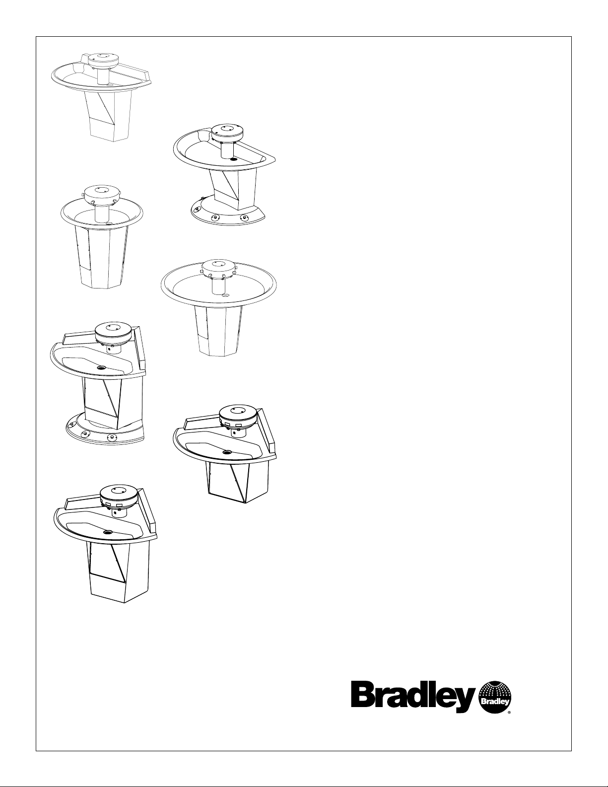
SN2003 (AST shown)
SN2005 (AST shown)
SN2013 (AST-4 shown)
SN2004 (AST-F shown)
SN2008 (AST shown)
SN2003
36" Semi-Circular, Floor-Mounted
SN2004
54" Semi-Circular, Floor-Mounted
SN2023
36" Semi-Circular, Wall-Mounted
SN2024
54" Semi-Circular, Wall-Mounted
SN2005
36" Circular, Floor-Mounted
SN2008
54" Circular, Floor-Mounted
SN2013
54" Corner, Floor-Mounted
SN2033
54" Corner, Wall-Mounted
SN2033 (IR shown)
SN2023 (IR shown)
215-1473 Rev. D; ECN 15-00-002
© 2015 Bradley
Page 1 of 31 3/24/2015
Table of Contents
How to Determine Drain Type ...................................................... 2
IR Assemblies, Troubleshooting and Wiring ................................ 3
Sentry Transformers ................................................................... 13
Supply Valves ........................................................................... 14
AST4 Assemblies, Adjustments and Troublshooting ................. 16
Thermostatic Mixing Valve Troubleshooting ............................... 23
Manual Mixing and Control Valves............................................. 25
Check Valve Troubleshooting Instructions ................................. 26
Care and Cleaning of Stainless Steel Sentry Washfountains .... 26
Soap System ............................................................................. 27
Pedestal Assembly..................................................................... 29
Backsplash Retrofit Kits ............................................................. 30
Shroud/Towel Dispensers .......................................................... 31
P.O. Box 309, Menomonee Falls, WI USA 53052-0309
800 BRADLEY (800 272 3539) +1 262 251 6000
bradleycorp.com
Sentry Washfountain Parts and Service Guide (Prior to February 1, 2013)
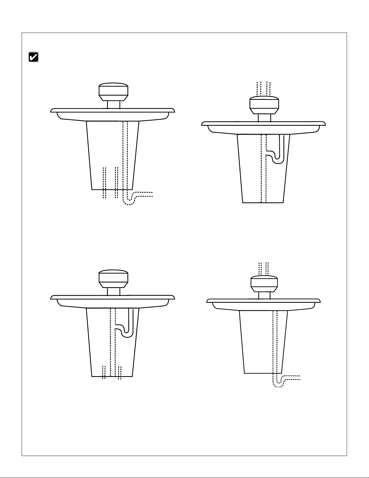
How to Determine Drain Type
Parts may vary depending upon drain type. Identify your drain type before continuing.
TYPE A:
SUPPLIES BELOW
VENT OFF DRAIN
P-TRAP FURNISHED BY OTHERS
TYPE B:
SUPPLIES ABOVE
CENTRALLY-RISING VENT
P-TRAP FURNISHED
TYPE H:
SUPPLIES BELOW
CENTRALLY-RISING VENT
P-TRAP FURNISHED
2
3/24/2015 Bradley • 215-1473 Rev. D; ECN 15-00-002
TYPE O:
SUPPLIES ABOVE
VENT OFF DRAIN
P-TRAP FURNISHED BY OTHERS
Parts and Service Guide (Prior to February 1, 2013) Sentry Washfountain
Infrared (IR) — Sprayhead Assembly
1
2
7
6
8
3
4
5
9
10
12
11
Parts List — Infrared Sensor and Module
Item Part No. Description
1 — Shell 1 1 1 1 1
2 269-982 Lens (window) 3 3 4 5 8
3 160-245 Screw 10-24 x 1/2" 6 6 8 10 16
4 142-002BT Lock Washer 6 6 8 10 16
5 142-002AV Flat washer 6 6 8 10 16
6 269-1184 Sensor 3 3 4 5 8
7 182-100 Lens Support (Rubber Block) 3 3 4 5 8
8 159-363 Sensor Mounting Bracket 3 3 4 5 8
9 161-082 Nut - Extension 1/4"-20 x 5-1/8" 2 2 2 2 2
10 269-621 Terminal - female disconnect 9 9 12 15 24
11 S05-157 Aerator Assembly (Std 0.5 GPM) 3 3 4 5 8
11 S05-172 Aerator Assembly (Optional 1.5
GPM)
12 110-115 Nut - 1/2" - 14 3 3 4 5 8
54" Corner
Qty.
3 3 4 5 8
36" Semi
Qty.
54" Semi
Qty.
36" Circle
Qty.
Parts List — Aerator Assembly
Item Part No. Description
1 S05-142A Std. Aerator, 0.5 GPM 1 —
1 153-397 Extra Flow Aerator, 1.5 GPM — 1
2 153-402A Adapter 1 1
3 145-090 90° Connector 1/4" tube x 1/8" NPT 1 1
4* 130-141 Spanner Wrench for Aerator — —
*Spanner wrench not included in Assemblies
S05-157 S05-172
Qty
4
3
54" Circle
Qty.
2
1
Bradley • 215-1473 Rev. D; ECN 15-00-007 3/24/2015
3

Sentry Washfountain Parts and Service Guide (Prior to February 1, 2013)
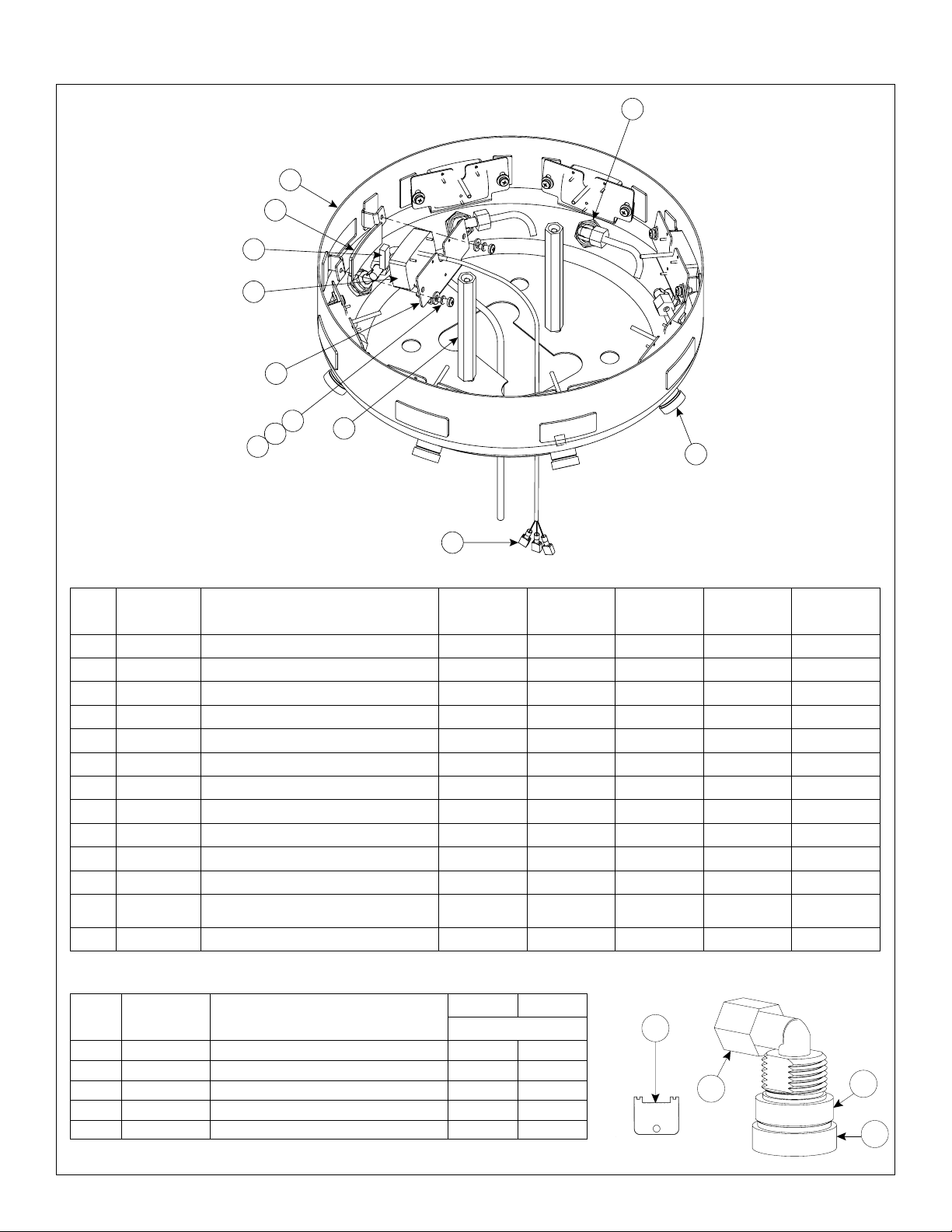
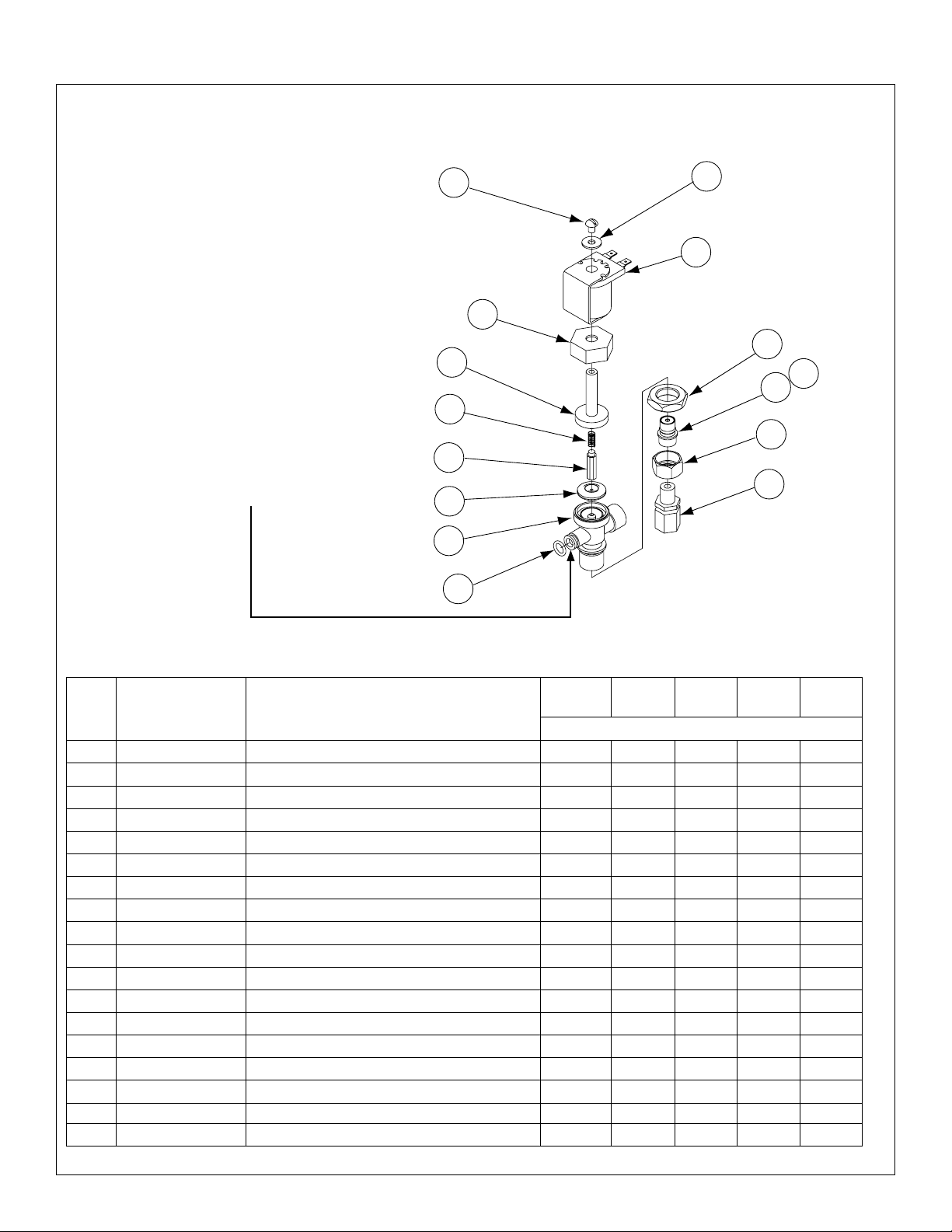
Infrared (IR) Part 1 — Solenoid Valve Assembly (24V Transformer)
Prior to February 1, 2013
6
5
4
3
2
14
1
11
7
8
12
10
13
3 Valve Assembly
Shown
9
Parts List — Solenoid Valve Assembly
54"
Item Part No. Description
1 S27-102 Stop/Check Valve 2 2 2 2 2
2 269-1735 Flex Hose 2 2 2 2 2
3 140-928 Bracket 1 1 1 — —
* 140-940 Bracket — — — 1 —
* 140-941 Bracket — — — — 1
4 269-625 Terminal Block 1 1 — 2 —
* 269-647 Terminal Block — — 1 — 2
5 P18-054 Screw #10-24 x 3/8 2 2 2 2 2
6 160-447 Screw #8-16 x 5/8 3 3 4 5 8
7 S01-524 Thermostatic Mixing Valve 1 1 1 1 1
8 S39-685 Adapter (Optional Single Tempered Line) 1 1 1 1 1
9 S07-067 Solenoid Valve - Closed Body (Black) 1 1 1 1 1
10 S07-067A Solenoid Valve - Thru Body (Gray) 2 2 3 4 7
11 R68-600011-B Tubing 1/4 OD Black ** ** ** ** **
12 R68-600011-G Tubing 1/4 OD Green ** ** ** ** **
13 R68-600011-R Tubing 1/4 OD Red ** ** ** ** **
* R68-600011-Y Tubing 1/4 OD Yellow — — ** ** **
* R68-600011 Tubing 1/4 OD Clear — — — ** —
14 S45-2146 Valve Assembly TMA 36S and 54K 1 1 — — —
* S45-2148 Valve Assembly TMA 54S — — 1 — —
* S45-2150 Valve Assembly TMA 36C — — — 1 —
* S45-2152 Valve Assembly TMA/IR 54C — — — — 1
Corner
36"
Semi
54"
Semi
Qty.
36"
Circle
54"
Circle
* Not Illustrated.
** Specify Length in feet.
4
3/24/2015 Bradley • 215-1473 Rev. D; ECN 15-00-002

Parts and Service Guide (Prior to February 1, 2013) Sentry Washfountain
Infrared (IR) Part 1 — Solenoid Valve Assembly (24V Transformer)
Prior to May 2, 2005
4
2
12
1
5
3
9
5
7
5 Valve Assembly
Shown
8
6
11
8
10
4 Valve Assembly
Shown
2
5
9
7
3
Supply Parts shown in
Supply Section
1
12
Parts List — Solenoid Valve Assembly
54"
Item Part No. Description
* S08-061 3 Valve Assy. with Bracket 1 1 — — —
1 S08-062 4 Valve Assy. with Bracket — — 1 — —
1 S08-358 5 Valve Assy. with Bracket — — — 1 —
* S08-359 8 Valve Assy. with Bracket — — — — 1
2 160-245 Screw for valve bracket 2 2 2 2 2
3 140-917 Valve Bracket - Semi & Corner 1 1 1 — —
3 140-918 Valve Bracket - Circle — — — 1 1
4 160-329 Screw 6-32 x 3/8" for terminal block 2 2 2 4 4
* 161-069 Lock Nut 6-32 for terminal block 2 2 2 4 4
5 269-625 Terminal Block - 3 Station 1 1 — 2 —
5 269-647 Terminal Block - 4 Station — — 1 — 2
* S53-128 Wire Assy. Black 3 3 4 5 8
* S53-129 Wire Assy. Red 3 3 4 5 8
* 269-645 Transformer 4RT Hard Wire 24V 1 1 1 — —
* 269-703 Transformer 8RT Hardwire 24V - Circle — — — 1 1
6 269-1248 U-Bolt 1 1 1 1 1
7 161-026 Nut 1/4"-20 2 2 2 2 2
8 269-1365 Hose - Braided Flexible 1 1 1 2 2
9 R68-600011 Tubing 1/4" OD (Specify Length in feet) — — — — —
10 269-1150 Tee - 1/2" Brass — — — 1 1
11 113-006DH 1/2" Close Nipple — — — 2 2
12 124-051 Anti-Rotation Gasket 1 1 — 2 —
12 124-052 Anti-Rotation Gasket — — 1 — 2
Corner
36"
Semi
54"
Semi
Qty.
36"
Circle
6
8
54"
Circle
* Specify Length in feet.
Bradley • 215-1473 Rev. D; ECN 15-00-007 3/24/2015
5
Sentry Washfountain Parts and Service Guide (Prior to February 1, 2013)
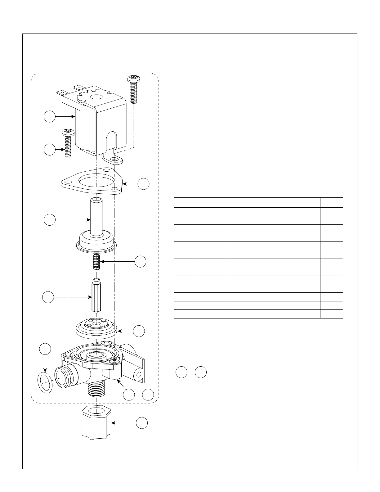
Infrared (IR) Part 2 — Solenoid Valve Assembly (24V Transformer)
Prior to February 1, 2013
11
10
9
Parts List — Solenoid Valve Assembly
Item Part No. Description Qty.
1 110-231 Nut 1/4 Tube 1
8
7
6
5
4
2 118-307 Valve Body 1/4" Closed 1
3 118-307A Valve Body 1/4" Thru 1
4 125-165 O-Ring 1
5 269-983 Diaphragm 1
6 269-577 Armature 1
7 269-578 Spring 1
8 269-1729 Armature Housing 1
9 269-1730 Clamp 1
10 160-447 Screw #8-16 x 5/8 3
11 269-579 Coil, Solenoid Valve 1
12 S07-067S Solenoid Valve Closed Body (Black) 1
13 S07-067AS Solenoid Valve Thru Body (Gray) 1
12 or
13
or
3
1
2
6
3/24/2015 Bradley • 215-1473 Rev. D; ECN 15-00-002
Parts and Service Guide (Prior to February 1, 2013) Sentry Washfountain
Infrared (IR) Part 2 — Solenoid Valve Assembly (24V Transformer)
S07-040 Individual (End), S07-041 Ganged
(Prior to May 2, 2005)
S07-040 Solenoid Valve (Individual)
Used by itself, or is the last one (opposite
end of the water inlet) in a group.
S07-041 Solenoid Valve (Ganged)
Used in a group, except the last in line.
Body is drilled to allow water to pass thru
into the next in line. This valve includes
O-Ring 125-145 to seal to the next valve.
1
4
5
6
7
8
2
3
11
13
12
14
15
9
10
Parts List — Solenoid Valve Assembly
54"
Item Part No. Description
1–9 S07-040 Valve Individual 1 1 1 2 2
1–10 S07-041 Valve Ganged 2 2 3 3 6
1 160-066 Screw 10-24 x 1/4 RD 3 3 4 5 8
2 142-002AZ Washer Stainless Steel 3 3 4 5 8
3 269-579 Coil - Solenoid Valve 3 3 4 5 8
4 110-194 Nut - Bonnet 3 3 4 5 8
5 121-028 Bonnet 3 3 4 5 8
6 269-578 Spring 3 3 4 5 8
7 269-577 Armature 3 3 4 5 8
8 269-580 Diaphragm 3 3 4 5 8
9 118-237 Valve Body Individual 1 1 1 2 2
9 118-238 Valve Body Ganged 2 2 3 3 6
10 125-145 O-Ring (for ganged valve body) 2 2 3 3 6
11 110-224 Nut 3 3 4 5 8
12 129-049 Tailpiece 3 3 4 5 8
13 125-145 O-Ring 3 3 4 5 8
14 110-195 Tailpiece Nut 3 3 4 5 8
15 145-090 Elbow, 1/8 NPTM x 1/4 Tube 3 3 4 5 8
Corner
36"
Semi
54"
Semi
Qty.
36"
Circle
54"
Circle
Bradley • 215-1473 Rev. D; ECN 15-00-007 3/24/2015
7
Sentry Washfountain Parts and Service Guide (Prior to February 1, 2013)
Infrared (IR) — Sensor and Solenoid Valve Troubleshooting
If a station is not functioning properly it is most likely either the solenoid valve or the sensor.
Troubleshooting multi station units is fairly easy, as you can swap parts (actually just by changing the wires) and use
the process of elimination to figure out which of the 2 parts is causing the problem.
How the system operates:
1. The transformer sends 24 volts to the sensor.
2. The sensor acts only as a switch.
3. When hands go into the active field of the sensor, the sensor activates and sends a power signal on to the
solenoid valve.
4. The power signal activates and opens the solenoid valve which allows the water to flow to the sprayhead.
The solenoid valve stays open allowing water to flow as long as it is receiving a signal form the sensor
(hands remain in the active field).
5. When hands are removed from the active field, the sensor turns off (note some models have a slight delay
feature built-in.) and shuts off the power signal to the solenoid valve.
CAUTION: Turn off water supplies to unit before troubleshooting.
Problem Cause Solution
An individual
operating station
fails to shut off and
drips.
An individual
operating station
fails to turn on.
There is debris
trapped between
the diaphragm
and the valve
seat.
A failed coil for
the valve or
loose electrical
connection to the
terminal.
Remove debris between diaphragm and the valve seat.
1. Remove the three #8 Phillips-head screws that hold the solenoid valve assembly
together. Be careful not to lose the armature or spring.
2. Remove the diaphragm. Remove any particles that have been trapped between the
diaphragm and the valve seat. Rinse off the diaphragm and inspect for damage.
Make sure the center orifice and both small side orifices are open.
3. Reassemble in reverse order, being careful not to overtighten the Phillips-head
screws or you may crack the plastic valve body. Tighten until the armature plate
makes contact with the plastic body.
4. Reconnect the wiring per the appropriate diagram on next 4 pages.
Test the station to determine cause.
1. Disconnect the wires from the coil of an adjacent valve. Disconnect the wires from
the problem valve and reconnect to the adjacent valve.
2. Turn on electrical and water supplies to the unit. Pass your hand in front of the
sensor of the problem station, and the adjacent station should turn on.
a. If the adjacent station turns on and cycles normally, replace the coil on the
b. If the adjacent valve fails to turn on, inspect the wires from the sensor cable
problem valve.
and do the following:
• make sure there are no breaks and that the fully insulated disconnect
terminals are firmly crimped in place;
• turn off the electrical and water supplies;
• reconnect to the adjacent valve and turn on the water supplies to the unit;
• pass your hand in front of the sensor. If the station still fails to turn on,
replace the sensor.
8
3/24/2015 Bradley • 215-1473 Rev. D; ECN 15-00-002

Parts and Service Guide (Prior to February 1, 2013) Sentry Washfountain
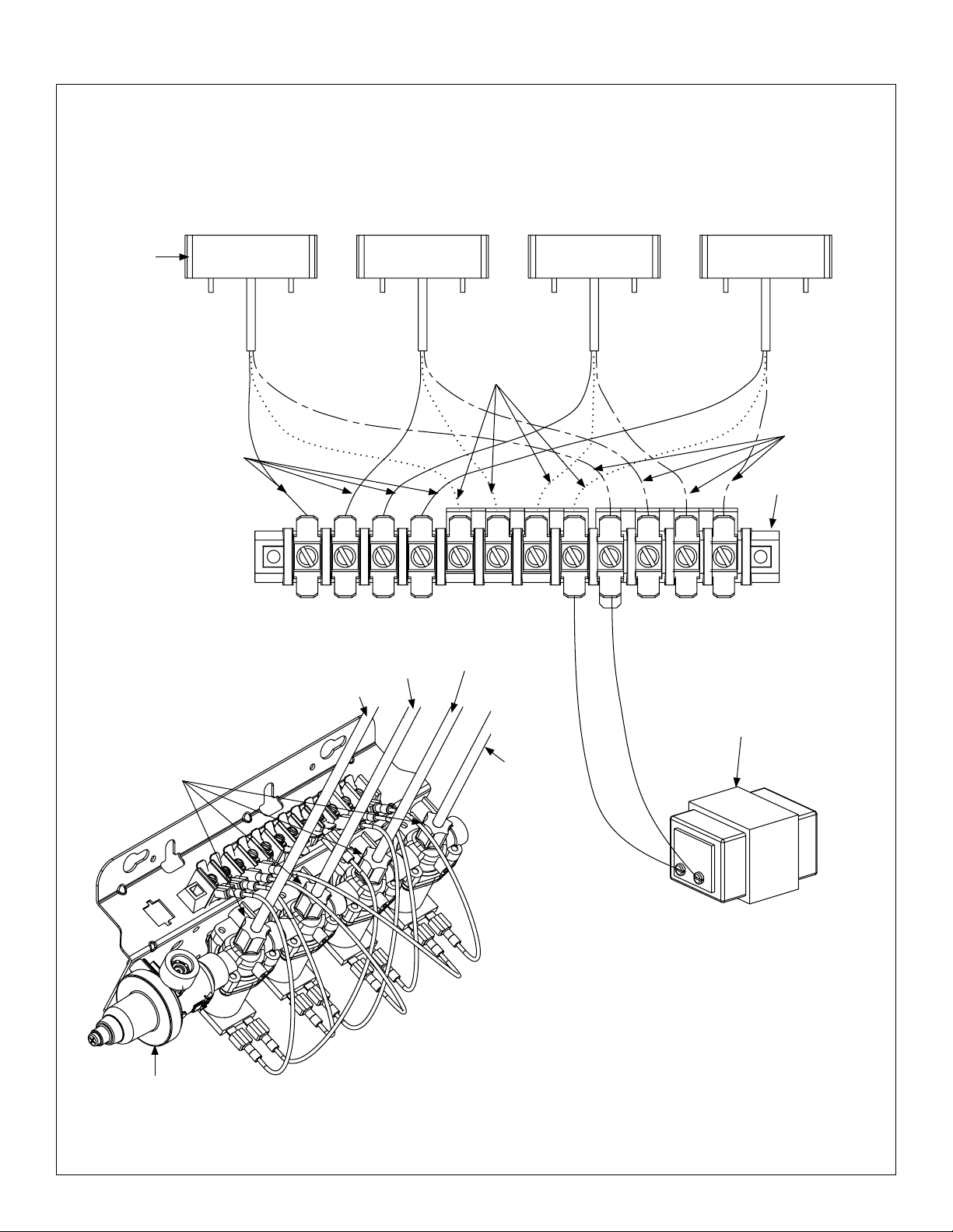
Infrared (IR) SN2003, SN2023, SN2013, SN2033 Wiring Diagram
Prior to February 1, 2013
IR Sensor
(269-1184)
Black
Left
Sensor
(Black)
3
Black
Center
Sensor
(Green)
2
Blue
Blue
Right Sensor
(Red)
1
Red
Terminal Block
(269-625)
Brown
To p
Navigator Mixing
Valve or Tempered
Line Adaptor
Transformer
(269-645)
Green Supply Tube
Black Supply Tube
Compression Nut
Red Supply
Tube
To p
Valve Set
(S45-2521 or S45-2522)
1
2
3
Bradley • 215-1473 Rev. D; ECN 15-00-007 3/24/2015
9
Sentry Washfountain Parts and Service Guide (Prior to February 1, 2013)
Infrared (IR) SN2004, SN2024 Wiring Diagram
Prior to February 1, 2013
IR Sensor
(269-1184)
Sensor
(Yellow)
Black
Sensor
4
Black Blue Red
(Black)
3
Blue
Sensor
(Green)
2
Sensor
(Red)
1
Brown
Terminal Block
(269-647)
To p
RightLeft
Compression Nut
Navigator
Mixing Valve or
Tempered Line
Adaptor
Black Supply Tube
Yellow Supply Tube
3
4
Green Supply
Tube
Transformer
(269-645)
Red Supply
Tube
To p
1
2
Valve Set
(S45-2523 or S45-2524)
10
3/24/2015 Bradley • 215-1473 Rev. D; ECN 15-00-002
 Loading...