

Page 1
Parts & Service
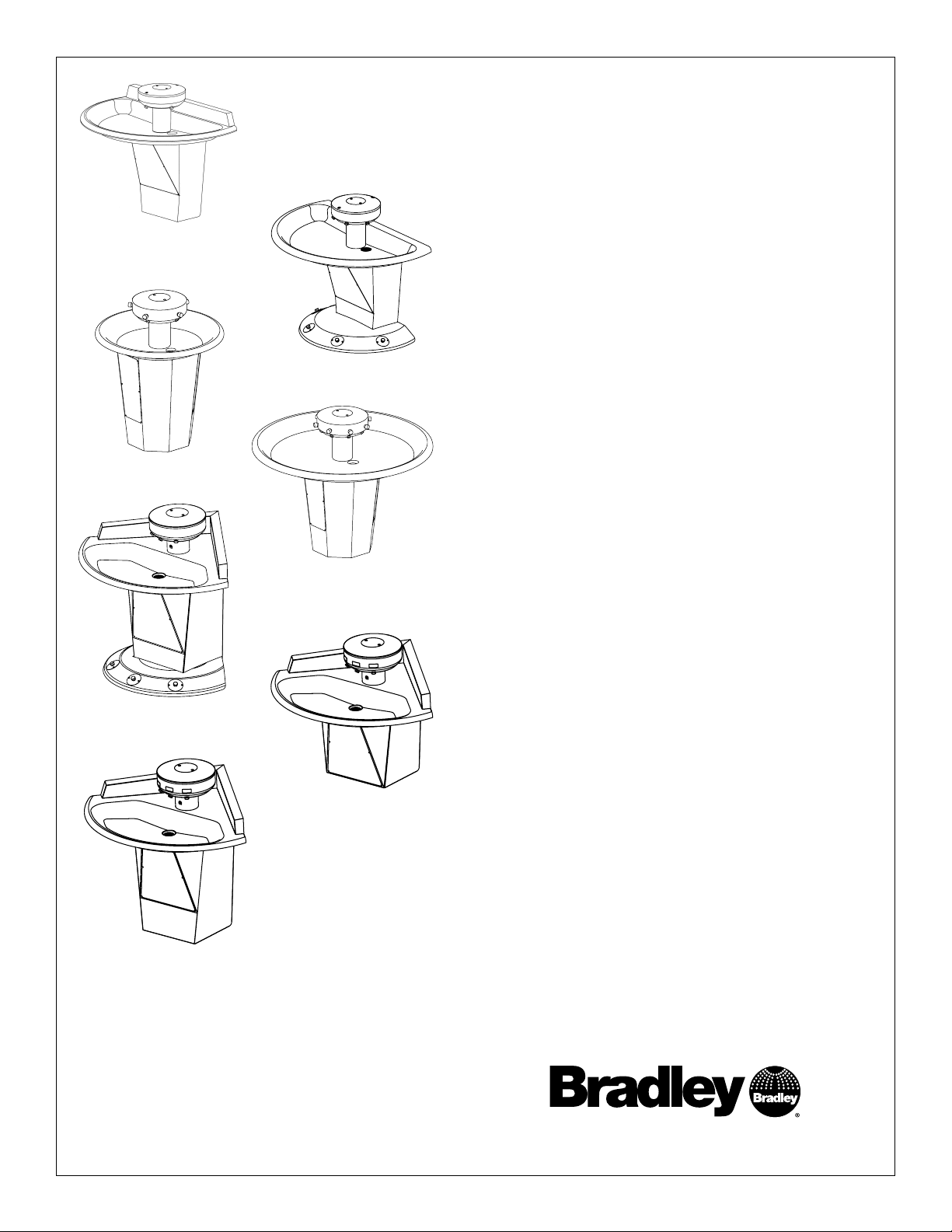
Sentry Washfountain
Discontinued Models Prior to
February 1, 2013
SN2003 (AST shown)
SN2005 (AST shown)
SN2013 (AST-4 shown)
SN2004 (AST-F shown)
SN2008 (AST shown)
SN2003
36" Semi-Circular, Floor-Mounted
SN2004
54" Semi-Circular, Floor-Mounted
SN2023
36" Semi-Circular, Wall-Mounted
SN2024
54" Semi-Circular, Wall-Mounted
SN2005
36" Circular, Floor-Mounted
SN2008
54" Circular, Floor-Mounted
SN2013
54" Corner, Floor-Mounted
SN2033
54" Corner, Wall-Mounted
SN2033 (IR shown)
SN2023 (IR shown)
215-1473 Rev. D; ECN 15-00-002
© 2015 Bradley
Page 1 of 31 3/24/2015
Table of Contents
How to Determine Drain Type ...................................................... 2
IR Assemblies, Troubleshooting and Wiring ................................ 3
Sentry Transformers ................................................................... 13
Supply Valves ........................................................................... 14
AST4 Assemblies, Adjustments and Troublshooting ................. 16
Thermostatic Mixing Valve Troubleshooting ............................... 23
Manual Mixing and Control Valves............................................. 25
Check Valve Troubleshooting Instructions ................................. 26
Care and Cleaning of Stainless Steel Sentry Washfountains .... 26
Soap System ............................................................................. 27
Pedestal Assembly..................................................................... 29
Backsplash Retrofit Kits ............................................................. 30
Shroud/Towel Dispensers .......................................................... 31
P.O. Box 309, Menomonee Falls, WI USA 53052-0309
800 BRADLEY (800 272 3539) +1 262 251 6000
bradleycorp.com
Page 2
Sentry Washfountain Parts and Service Guide (Prior to February 1, 2013)
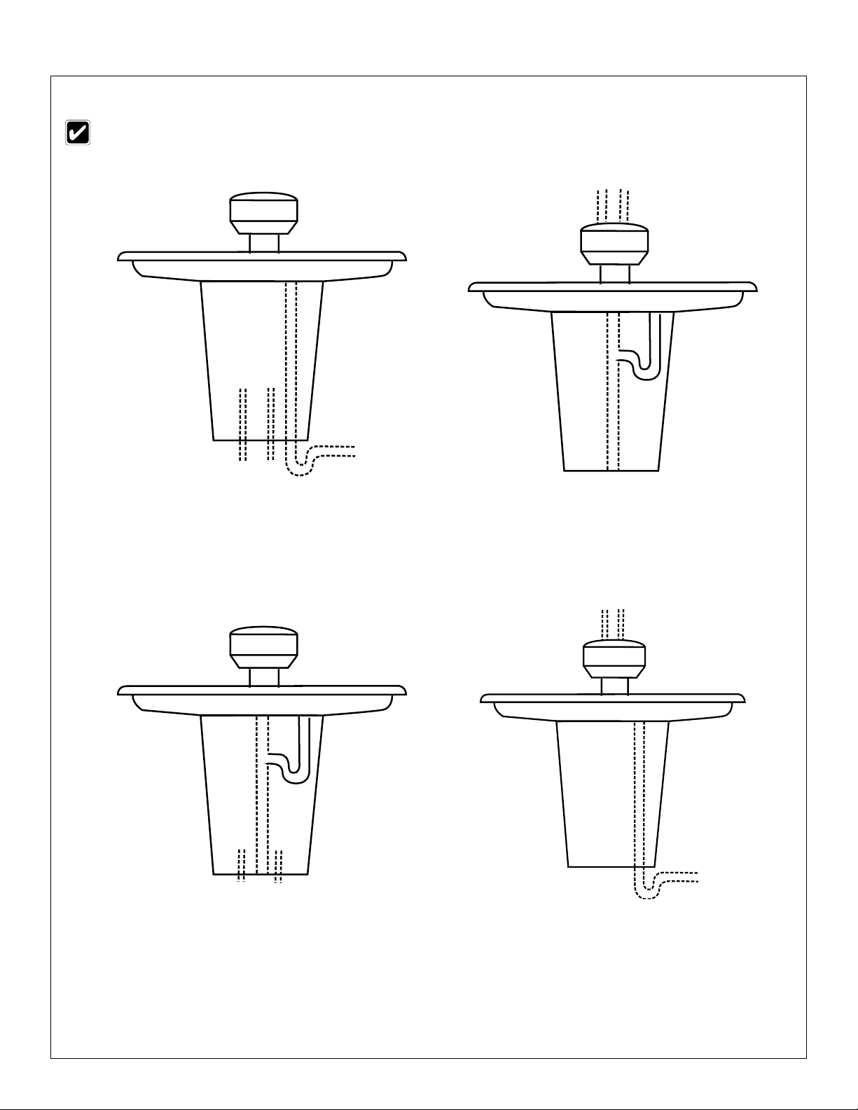
How to Determine Drain Type
Parts may vary depending upon drain type. Identify your drain type before continuing.
TYPE A:
SUPPLIES BELOW
VENT OFF DRAIN
P-TRAP FURNISHED BY OTHERS
TYPE B:
SUPPLIES ABOVE
CENTRALLY-RISING VENT
P-TRAP FURNISHED
TYPE H:
SUPPLIES BELOW
CENTRALLY-RISING VENT
P-TRAP FURNISHED
2
3/24/2015 Bradley • 215-1473 Rev. D; ECN 15-00-002
TYPE O:
SUPPLIES ABOVE
VENT OFF DRAIN
P-TRAP FURNISHED BY OTHERS
Page 3
Parts and Service Guide (Prior to February 1, 2013) Sentry Washfountain
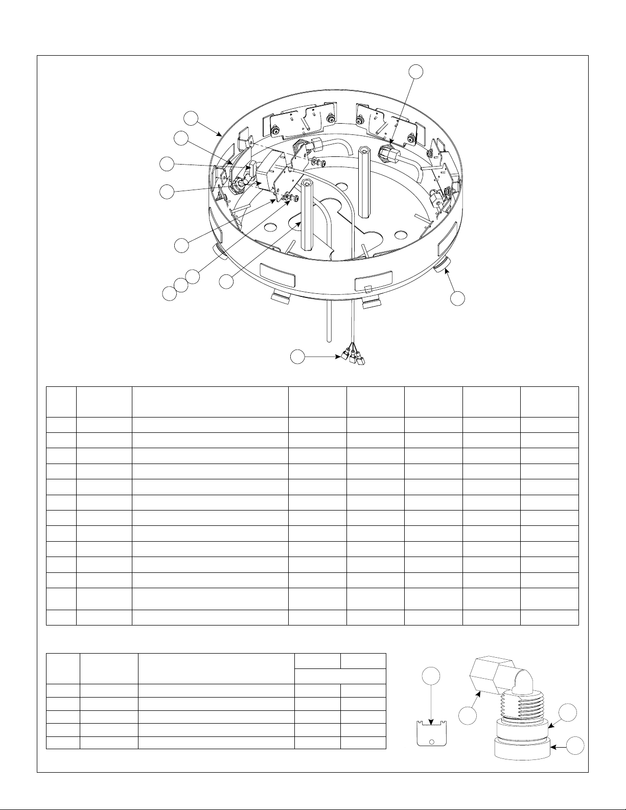
Infrared (IR) — Sprayhead Assembly
1
2
7
6
8
3
4
5
9
10
12
11
Parts List — Infrared Sensor and Module
Item Part No. Description
1 — Shell 1 1 1 1 1
2 269-982 Lens (window) 3 3 4 5 8
3 160-245 Screw 10-24 x 1/2" 6 6 8 10 16
4 142-002BT Lock Washer 6 6 8 10 16
5 142-002AV Flat washer 6 6 8 10 16
6 269-1184 Sensor 3 3 4 5 8
7 182-100 Lens Support (Rubber Block) 3 3 4 5 8
8 159-363 Sensor Mounting Bracket 3 3 4 5 8
9 161-082 Nut - Extension 1/4"-20 x 5-1/8" 2 2 2 2 2
10 269-621 Terminal - female disconnect 9 9 12 15 24
11 S05-157 Aerator Assembly (Std 0.5 GPM) 3 3 4 5 8
11 S05-172 Aerator Assembly (Optional 1.5
GPM)
12 110-115 Nut - 1/2" - 14 3 3 4 5 8
54" Corner
Qty.
3 3 4 5 8
36" Semi
Qty.
54" Semi
Qty.
36" Circle
Qty.
Parts List — Aerator Assembly
Item Part No. Description
1 S05-142A Std. Aerator, 0.5 GPM 1 —
1 153-397 Extra Flow Aerator, 1.5 GPM — 1
2 153-402A Adapter 1 1
3 145-090 90° Connector 1/4" tube x 1/8" NPT 1 1
4* 130-141 Spanner Wrench for Aerator — —
*Spanner wrench not included in Assemblies
S05-157 S05-172
Qty
4
3
54" Circle
Qty.
2
1
Bradley • 215-1473 Rev. D; ECN 15-00-007 3/24/2015
3
Page 4

Sentry Washfountain Parts and Service Guide (Prior to February 1, 2013)
Infrared (IR) Part 1 — Solenoid Valve Assembly (24V Transformer)
Prior to February 1, 2013
6
5
4
3
2
14
1
11
7
8
12
10
13
3 Valve Assembly
Shown
9
Parts List — Solenoid Valve Assembly
54"
Item Part No. Description
1 S27-102 Stop/Check Valve 2 2 2 2 2
2 269-1735 Flex Hose 2 2 2 2 2
3 140-928 Bracket 1 1 1 — —
* 140-940 Bracket — — — 1 —
* 140-941 Bracket — — — — 1
4 269-625 Terminal Block 1 1 — 2 —
* 269-647 Terminal Block — — 1 — 2
5 P18-054 Screw #10-24 x 3/8 2 2 2 2 2
6 160-447 Screw #8-16 x 5/8 3 3 4 5 8
7 S01-524 Thermostatic Mixing Valve 1 1 1 1 1
8 S39-685 Adapter (Optional Single Tempered Line) 1 1 1 1 1
9 S07-067 Solenoid Valve - Closed Body (Black) 1 1 1 1 1
10 S07-067A Solenoid Valve - Thru Body (Gray) 2 2 3 4 7
11 R68-600011-B Tubing 1/4 OD Black ** ** ** ** **
12 R68-600011-G Tubing 1/4 OD Green ** ** ** ** **
13 R68-600011-R Tubing 1/4 OD Red ** ** ** ** **
* R68-600011-Y Tubing 1/4 OD Yellow — — ** ** **
* R68-600011 Tubing 1/4 OD Clear — — — ** —
14 S45-2146 Valve Assembly TMA 36S and 54K 1 1 — — —
* S45-2148 Valve Assembly TMA 54S — — 1 — —
* S45-2150 Valve Assembly TMA 36C — — — 1 —
* S45-2152 Valve Assembly TMA/IR 54C — — — — 1
Corner
36"
Semi
54"
Semi
Qty.
36"
Circle
54"
Circle
* Not Illustrated.
** Specify Length in feet.
4
3/24/2015 Bradley • 215-1473 Rev. D; ECN 15-00-002
Page 5

Parts and Service Guide (Prior to February 1, 2013) Sentry Washfountain
Infrared (IR) Part 1 — Solenoid Valve Assembly (24V Transformer)
Prior to May 2, 2005
4
2
12
1
5
3
9
5
7
5 Valve Assembly
Shown
8
6
11
8
10
4 Valve Assembly
Shown
2
5
9
7
3
Supply Parts shown in
Supply Section
1
12
Parts List — Solenoid Valve Assembly
54"
Item Part No. Description
* S08-061 3 Valve Assy. with Bracket 1 1 — — —
1 S08-062 4 Valve Assy. with Bracket — — 1 — —
1 S08-358 5 Valve Assy. with Bracket — — — 1 —
* S08-359 8 Valve Assy. with Bracket — — — — 1
2 160-245 Screw for valve bracket 2 2 2 2 2
3 140-917 Valve Bracket - Semi & Corner 1 1 1 — —
3 140-918 Valve Bracket - Circle — — — 1 1
4 160-329 Screw 6-32 x 3/8" for terminal block 2 2 2 4 4
* 161-069 Lock Nut 6-32 for terminal block 2 2 2 4 4
5 269-625 Terminal Block - 3 Station 1 1 — 2 —
5 269-647 Terminal Block - 4 Station — — 1 — 2
* S53-128 Wire Assy. Black 3 3 4 5 8
* S53-129 Wire Assy. Red 3 3 4 5 8
* 269-645 Transformer 4RT Hard Wire 24V 1 1 1 — —
* 269-703 Transformer 8RT Hardwire 24V - Circle — — — 1 1
6 269-1248 U-Bolt 1 1 1 1 1
7 161-026 Nut 1/4"-20 2 2 2 2 2
8 269-1365 Hose - Braided Flexible 1 1 1 2 2
9 R68-600011 Tubing 1/4" OD (Specify Length in feet) — — — — —
10 269-1150 Tee - 1/2" Brass — — — 1 1
11 113-006DH 1/2" Close Nipple — — — 2 2
12 124-051 Anti-Rotation Gasket 1 1 — 2 —
12 124-052 Anti-Rotation Gasket — — 1 — 2
Corner
36"
Semi
54"
Semi
Qty.
36"
Circle
6
8
54"
Circle
* Specify Length in feet.
Bradley • 215-1473 Rev. D; ECN 15-00-007 3/24/2015
5
Page 6
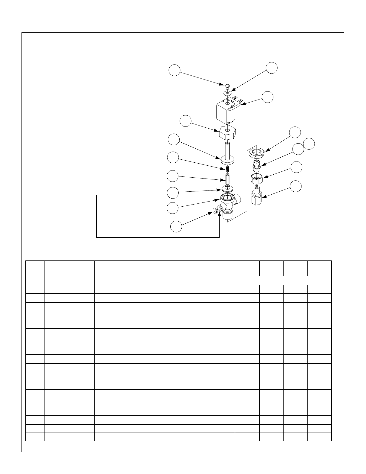
Sentry Washfountain Parts and Service Guide (Prior to February 1, 2013)
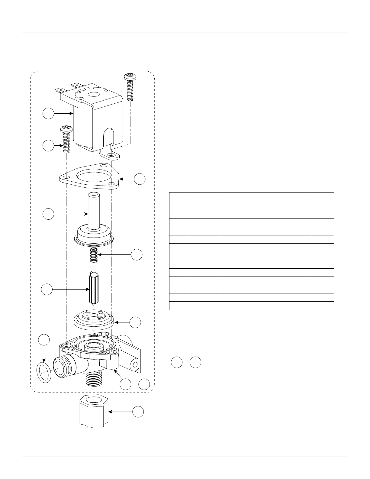
Infrared (IR) Part 2 — Solenoid Valve Assembly (24V Transformer)
Prior to February 1, 2013
11
10
9
Parts List — Solenoid Valve Assembly
Item Part No. Description Qty.
1 110-231 Nut 1/4 Tube 1
8
7
6
5
4
2 118-307 Valve Body 1/4" Closed 1
3 118-307A Valve Body 1/4" Thru 1
4 125-165 O-Ring 1
5 269-983 Diaphragm 1
6 269-577 Armature 1
7 269-578 Spring 1
8 269-1729 Armature Housing 1
9 269-1730 Clamp 1
10 160-447 Screw #8-16 x 5/8 3
11 269-579 Coil, Solenoid Valve 1
12 S07-067S Solenoid Valve Closed Body (Black) 1
13 S07-067AS Solenoid Valve Thru Body (Gray) 1
12 or
13
or
3
1
2
6
3/24/2015 Bradley • 215-1473 Rev. D; ECN 15-00-002
Page 7
Parts and Service Guide (Prior to February 1, 2013) Sentry Washfountain
Infrared (IR) Part 2 — Solenoid Valve Assembly (24V Transformer)
S07-040 Individual (End), S07-041 Ganged
(Prior to May 2, 2005)
S07-040 Solenoid Valve (Individual)
Used by itself, or is the last one (opposite
end of the water inlet) in a group.
S07-041 Solenoid Valve (Ganged)
Used in a group, except the last in line.
Body is drilled to allow water to pass thru
into the next in line. This valve includes
O-Ring 125-145 to seal to the next valve.
1
4
5
6
7
8
2
3
11
13
12
14
15
9
10
Parts List — Solenoid Valve Assembly
54"
Item Part No. Description
1–9 S07-040 Valve Individual 1 1 1 2 2
1–10 S07-041 Valve Ganged 2 2 3 3 6
1 160-066 Screw 10-24 x 1/4 RD 3 3 4 5 8
2 142-002AZ Washer Stainless Steel 3 3 4 5 8
3 269-579 Coil - Solenoid Valve 3 3 4 5 8
4 110-194 Nut - Bonnet 3 3 4 5 8
5 121-028 Bonnet 3 3 4 5 8
6 269-578 Spring 3 3 4 5 8
7 269-577 Armature 3 3 4 5 8
8 269-580 Diaphragm 3 3 4 5 8
9 118-237 Valve Body Individual 1 1 1 2 2
9 118-238 Valve Body Ganged 2 2 3 3 6
10 125-145 O-Ring (for ganged valve body) 2 2 3 3 6
11 110-224 Nut 3 3 4 5 8
12 129-049 Tailpiece 3 3 4 5 8
13 125-145 O-Ring 3 3 4 5 8
14 110-195 Tailpiece Nut 3 3 4 5 8
15 145-090 Elbow, 1/8 NPTM x 1/4 Tube 3 3 4 5 8
Corner
36"
Semi
54"
Semi
Qty.
36"
Circle
54"
Circle
Bradley • 215-1473 Rev. D; ECN 15-00-007 3/24/2015
7
Page 8

Sentry Washfountain Parts and Service Guide (Prior to February 1, 2013)
Infrared (IR) — Sensor and Solenoid Valve Troubleshooting
If a station is not functioning properly it is most likely either the solenoid valve or the sensor.
Troubleshooting multi station units is fairly easy, as you can swap parts (actually just by changing the wires) and use
the process of elimination to figure out which of the 2 parts is causing the problem.
How the system operates:
1. The transformer sends 24 volts to the sensor.
2. The sensor acts only as a switch.
3. When hands go into the active field of the sensor, the sensor activates and sends a power signal on to the
solenoid valve.
4. The power signal activates and opens the solenoid valve which allows the water to flow to the sprayhead.
The solenoid valve stays open allowing water to flow as long as it is receiving a signal form the sensor
(hands remain in the active field).
5. When hands are removed from the active field, the sensor turns off (note some models have a slight delay
feature built-in.) and shuts off the power signal to the solenoid valve.
CAUTION: Turn off water supplies to unit before troubleshooting.
Problem Cause Solution
An individual
operating station
fails to shut off and
drips.
An individual
operating station
fails to turn on.
There is debris
trapped between
the diaphragm
and the valve
seat.
A failed coil for
the valve or
loose electrical
connection to the
terminal.
Remove debris between diaphragm and the valve seat.
1. Remove the three #8 Phillips-head screws that hold the solenoid valve assembly
together. Be careful not to lose the armature or spring.
2. Remove the diaphragm. Remove any particles that have been trapped between the
diaphragm and the valve seat. Rinse off the diaphragm and inspect for damage.
Make sure the center orifice and both small side orifices are open.
3. Reassemble in reverse order, being careful not to overtighten the Phillips-head
screws or you may crack the plastic valve body. Tighten until the armature plate
makes contact with the plastic body.
4. Reconnect the wiring per the appropriate diagram on next 4 pages.
Test the station to determine cause.
1. Disconnect the wires from the coil of an adjacent valve. Disconnect the wires from
the problem valve and reconnect to the adjacent valve.
2. Turn on electrical and water supplies to the unit. Pass your hand in front of the
sensor of the problem station, and the adjacent station should turn on.
a. If the adjacent station turns on and cycles normally, replace the coil on the
b. If the adjacent valve fails to turn on, inspect the wires from the sensor cable
problem valve.
and do the following:
• make sure there are no breaks and that the fully insulated disconnect
terminals are firmly crimped in place;
• turn off the electrical and water supplies;
• reconnect to the adjacent valve and turn on the water supplies to the unit;
• pass your hand in front of the sensor. If the station still fails to turn on,
replace the sensor.
8
3/24/2015 Bradley • 215-1473 Rev. D; ECN 15-00-002
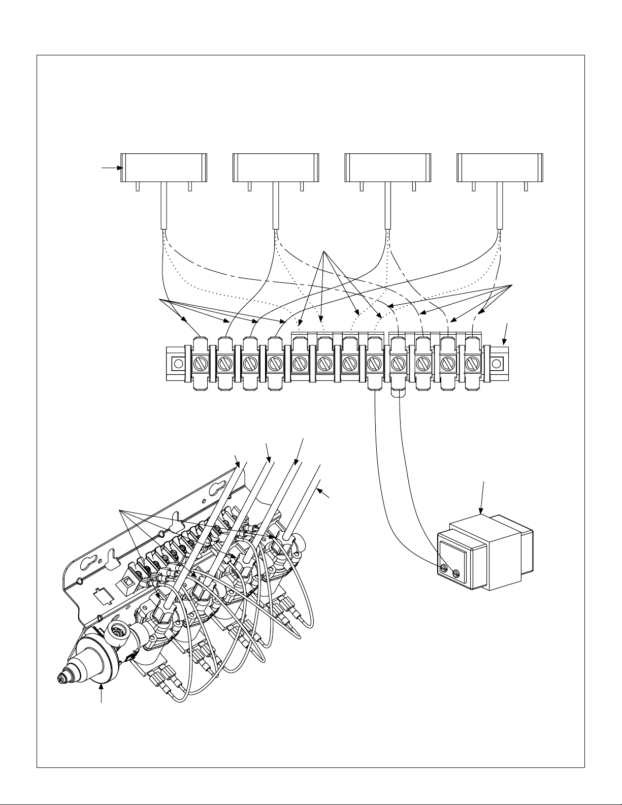
Page 9

Parts and Service Guide (Prior to February 1, 2013) Sentry Washfountain
Infrared (IR) SN2003, SN2023, SN2013, SN2033 Wiring Diagram
Prior to February 1, 2013
IR Sensor
(269-1184)
Black
Left
Sensor
(Black)
3
Black
Center
Sensor
(Green)
2
Blue
Blue
Right Sensor
(Red)
1
Red
Terminal Block
(269-625)
Brown
To p
Navigator Mixing
Valve or Tempered
Line Adaptor
Transformer
(269-645)
Green Supply Tube
Black Supply Tube
Compression Nut
Red Supply
Tube
To p
Valve Set
(S45-2521 or S45-2522)
1
2
3
Bradley • 215-1473 Rev. D; ECN 15-00-007 3/24/2015
9
Page 10
Sentry Washfountain Parts and Service Guide (Prior to February 1, 2013)
Infrared (IR) SN2004, SN2024 Wiring Diagram
Prior to February 1, 2013
IR Sensor
(269-1184)
Sensor
(Yellow)
Black
Sensor
4
Black Blue Red
(Black)
3
Blue
Sensor
(Green)
2
Sensor
(Red)
1
Brown
Terminal Block
(269-647)
To p
RightLeft
Compression Nut
Navigator
Mixing Valve or
Tempered Line
Adaptor
Black Supply Tube
Yellow Supply Tube
3
4
Green Supply
Tube
Transformer
(269-645)
Red Supply
Tube
To p
1
2
Valve Set
(S45-2523 or S45-2524)
10
3/24/2015 Bradley • 215-1473 Rev. D; ECN 15-00-002
Page 11

Parts and Service Guide (Prior to February 1, 2013) Sentry Washfountain
Infrared (IR) SN2005 Wiring Diagram
Prior to February 1, 2013
IR Sensor
(269-1184)
Black
Sensor
(Clear)
5
Blue
Sensor
(Yellow)
4
Brown
Sensor
(Black)
3
Black
Sensor
(Green)
2
Blue
Transformer
(269-645)
Sensor
(Red)
1
RedBlueBlackRedBlueBlack
Brown
To p
Terminal Block
(269-625)
Clear Supply Tube
Compression Nut
Navigator
Mixing Valve or
Tempered Line
Adaptor
Black Supply Tube
Yellow Supply Tube
4
5
S45-2525 or S45-2526
Green Supply
Tube
Red Supply
Tube
To p
1
2
3
Valve Set
Bradley • 215-1473 Rev. D; ECN 15-00-007 3/24/2015
11
Page 12

Sentry Washfountain Parts and Service Guide (Prior to February 1, 2013)
Infrared (IR) SN2008 Wiring Diagram
Prior to February 1, 2013
IR Sensor
(269-1184)
Black
Sensor
(Yellow)
8
Black
Sensor
(Black)
7
Sensor
(Green)
6
Blue
Blue Red
Yellow Supply Tube
Sensor
(Red)
5
Brown
Black
Yellow Supply Tube
Red Supply Tube
Green Supply Tube
Black Supply Tube
Sensor
(Yellow)
4
Black
Transformer
(269-645)
Black Supply Tube
Sensor
(Black)
3
Blue
Blue Red
Green Supply Tube
Sensor
(Green)
2
Terminal Block
Red Supply Tube
Sensor
(Red)
1
Brown
To p
(269-647)
12
Compression Nut
Navigator®
Mixing Valve or
Tempered Line
Adaptor
3/24/2015 Bradley • 215-1473 Rev. D; ECN 15-00-002
To p
1
2
3
4
5
6
7
8
Valve Set
S45-2527 or S45-2528
Page 13

Parts and Service Guide (Prior to February 1, 2013) Sentry Washfountain
Sentry Transformers
Model Description
Part Number Qty. Part Number Qty.
SN2003 36" Semi-Circular – Floor Mounted S45-2045 1 269-645 1
SN2004 54" Semi-Circular – Floor Mounted S45-2045 1 269-645 1
SN2023 36" Semi-Circular – Wall Mounted S45-2045 1 269-645 1
SN2024 54" Semi-Circular – Wall Mounted S45-2045 1 269-645 1
SN2005 36" Circular – Floor Mounted S45-2045 2 * 269-703 1
SN2008 54" Circular – Floor Mounted S45-2045 2 * 269-703 1
SN2013 54" Corner – Floor Mounted S45-2045 1 269-645 1
SN2033 54" Corner – Wall Mounted S45-2045 1 269-645 1
Current Prior to May 2003
* Available for service
Bradley • 215-1473 Rev. D; ECN 15-00-007 3/24/2015
13
Page 14

Sentry Washfountain Parts and Service Guide (Prior to February 1, 2013)
Supply Valves
5
6
MMV — Manual Mixing
Complete Assy. as Shown - S67-203
(Prior to May 2, 2005)
8
4
6
5
1
4
2
4
4
5
5
6
TMA — Thermostatic Mixing
Complete Assy. as Shown - S67-571
(Prior to May 2, 2005)
14
7
4
5
6
5
TL — Tempered Line
Complete Assy. as Shown
S45-1966 (Prior to May 2, 2005)
12
13
4
13
5
5
10
PBV — Pressure Balancing
Complete Assy. as Shown - S67-516
(Prior to May 2, 2005)
11
9
TMA — Thermostatic Mixing
(Prior to February 1, 2013)
(Prior to February 1, 2013)
5
TL — Tempered LIne
Parts List — Supply Valves
MMV TMA TL PBV TMA TL
Item Part No. Description
(Prior to May 2, 2005)
Qty.
1 S01-038B Mixing Valve - Manual 1 — — — — —
2 S01-116B Mixing Valve - Thermostatic - Vernatherm — 1 — — — —
4 269-653 SS Flex Hose 1/2" NPT 2 2 1 2 — —
5 S27-102 Check Stop 2 2 1 2 2 1
*6 269-1188 Filter Washer 2 2 1 2 — —
7 113-006DH 1/2 x 1-1/2 Brass Pipe Nipple — — — 1 — —
8 S67-594 Valve — — — 1 — —
9 128-161 Handle for valve — — — 1 — —
*10 160-214 Screw for handle (PBV Valve only) — — — 1 — —
11 169-168 Pipe Plug for bottom of valve — — — 1 — —
12 S39-685 Adapter (Optional Single Tempered Line) — — — — — 1
13 269-1735 Flex Hose — — — — 2 1
14 S01-524 Thermostatic Mixing Valve — — — — 1 —
* Not Illustrated.
(prior to
Feb. 1, 2013)
14
3/24/2015 Bradley • 215-1473 Rev. D; ECN 15-00-002
Page 15

Parts and Service Guide (Prior to February 1, 2013) Sentry Washfountain
Air Metering Valve (AST4) — Hand Pushbutton and Sprayhead
(Prior to May 2, 2005)
Pushbutton Replacement
CAUTION: Turn off water supplies before replacing the
pushbutton.
1. Remove the sprayhead cover by removing the two
screws holding the cover to the sprayhead module.
2. Inside sprayhead, unscrew the two screws that hold
the actuator body to the bracket being careful of the
spring that will release.
3. Unscrew and remove the coupling if necessary.
4. Unscrew and remove the brass nut if necessary.
This will allow the pushbutton assembly to be
removed.
5. Carefully take apart the assembly and replace the
parts as needed.
6. After replacement is complete, reassemble the
pushbutton and sprayhead as shown.
11
14
10
9
8
7
2
16
20
17
12
13
5
4
3
2
6
16
15
18
Parts List — Pushbutton
21
Item Part No. Description
1 — Shell 1 1 1 1 1
2 S08-324 Pushbutton Assy. (includes items 3–5) 3 3 4 5 8
3 128-090 Pushbutton Only 3 3 4 5 8
4 179-102 Guide for Pushbutton 3 3 4 5 8
5 147-033 Screw for Pushbutton 3 3 4 5 8
6 140-743 Bracket - Actuator 3 3 4 5 8
7 110-115 Nut 1/2"-14 3 3 4 5 8
8 169-890 Connector 1/8" tube x 10-32 Thd. 3 3 4 5 8
9 269-1186 "L" Fitting Adjustable 3 3 4 5 8
10 118-279 Actuator Body 3 3 4 5 8
11 135-065 Spring 3 3 4 5 8
12 125-099 U-Cup for piston 3 3 4 5 8
13 119-227 Piston 3 3 4 5 8
14 160-165 Screw - Body mounting 6 6 8 10 16
15 R68-600008 Tubing 1/8" OD (specify length in feet) — — — — —
*16 S05-157 Aerator Assembly (Std 0.5 GPM) 3 3 4 5 8
*16 S05-172 Aerator Assembly (Optional 1.5 GPM) 3 3 4 5 8
17 110-115 Nut - 1/2" - 14 3 3 4 5 8
18 161-082 Nut - Extension 1/4"-20 x 5-1/8" 2 2 2 2 2
19 130-141 Spanner Wrench for Aerators 1 1 1 1 1
20 R68-600011 Tubing 1/4" OD (specify length in feet) — — — — —
21 130-023 Spanner Wrench for Pushbuttons 1 1 1 1 1
54" Corner
Qty.
Prepack S65-168A * See page 3 for additional information.
36" Semi
Qty.
54" Semi
Qty.
36" Circle
Qty.
54" Circle
Qty.
Bradley • 215-1473 Rev. D; ECN 15-00-007 3/24/2015
15
Page 16

Sentry Washfountain Parts and Service Guide (Prior to February 1, 2013)
Air Metering Valve (AST4-F) — Foot Pushbutton and Actuator
(Prior to May 2, 2005)
Parts List — Aerator Assembly
Item Part No. Description
1 S05-142A Standard Aerator, 0.5 GPM 1 —
1 153-397 Extra Flor Aerator, 1.5 GPM — 1
2 153-402A Adapter 1 1
3 145-090 90° Connector 1/4" tube x 1/8" NPT 1 1
4* 130-141 Spanner Wrench for Aerator — —
Foot Pushbutton Assembly
S45-1543
3
6
8
1
S05-157 S05-172
Qty.
Actuator Assembly S08-288
4
3
9
2
1
4
3
2
1
8
7
4
5
Parts List — Foot Pushbutton
Assembly (S45-1543)
Item Part No. Description Qty.
1 S08-288 Actuator Assy. 1
2 140-604 Bracket 1
3 150-198 Escutcheon 1
4 128-090 Pushbutton 1
5 179-071 Pushbutton Guide 1
6 110-115 Nut 1/2"-14 1
7 119-132 Plunger 1
8 160-245 Screw for escutcheon 2
2
5
7
6
Parts List — Actuator
Assembly (S08-288)
Item Part No. Description Qty.
1 160-276 Screw 8-32 x ¾" 4
2 140-493 Mounting Plate 1
3 269-612 Diaphragm 1
4 269-613 Back Plate 1
5 161-062 Nut 8-32 4
6 269-1186 Fitting adjustable "L" 1
7 142-002CR Washer #8 lock 4
8 125-001CZ O-Ring 1
9 169-890 Fitting - tube connector 10-32 x 1/8" 1
16
3/24/2015 Bradley • 215-1473 Rev. D; ECN 15-00-002
Page 17

Parts and Service Guide (Prior to February 1, 2013) Sentry Washfountain
Air Metering Valve (AST4) Part 1 — Assembly and Components
(Prior to February 1, 2013)
10
4
1211
3 Valve Assembly
Shown
5
3
6
16
8
14 15
13
7
2
1
9
Parts List — Air Metering Valve Assembly
54"
Item Part No. Description
1 S27-102 Stop/Check Valve 2 2 2 2 2
2 269-1735 Flex Hose 2 2 2 2 2
3 140-928 Bracket 1 1 1 — —
* 140-940 Bracket — — — 1 —
* 140-941 Bracket — — — — 1
4 P18-054 Screw #10-24 x 3/8 2 2 2 2 2
5 160-447 Screw #8-16 x 5/8 3 3 4 5 8
6 S01-524 Thermostatic Mixing Valve 1 1 1 1 1
7 S39-685 Adapter (Optional Single Tempered Line) 1 1 1 1 1
8 S07-077A AST4 Valve, through body (Gray) 2 2 3 4 7
9 S07-077 AST4 Valve, closed body (Black) 1 1 1 1 1
10 R68-600011-B Tubing 1/4 OD Black ** ** ** ** **
11 R68-600011-G Tubing 1/4 OD Green ** ** ** ** **
12 R68-600011-R Tubing 1/4 OD Red ** ** ** ** **
* R68-600011-Y Tubing 1/4 OD Yellow — — ** ** **
* R68-600011 Tubing 1/4 OD Clear — — — ** —
13 R68-600008-B Tubing 1/8 OD Black ** ** ** ** **
14 R68-600008-G Tubing 1/8 OD Green ** ** ** ** **
15 R68-600008-R Tubing 1/8 OD Red ** ** ** ** **
* R68-600008-Y Tubing 1/8 OD Yellow — — ** ** **
16 S08-443TMA Valve Assembly AST 1 1 — — —
* S08-444TMA Valve Assembly AST4 — — 1 — —
* S08-445TMA Valve Assembly AST4 — — — 1 —
* S08-448TMA Valve Assembly AST4 — — — — 1
Corner
* Not Illustrated.
** Specify Length in feet.
36"
Semi
54"
Semi
Qty.
36"
Circle
54"
Circle
Bradley • 215-1473 Rev. D; ECN 15-00-007 3/24/2015
17
Page 18

Sentry Washfountain Parts and Service Guide (Prior to February 1, 2013)
Air Metering Valve (AST) Part 1 — Assembly and Components
(Prior to May 2, 2013)
3
2
8 Valve Assembly
Shown
10
11
3 Valve Assembly
Shown
3
5
7
4
6
Supply Parts shown in Supply Section
8
5
9
4
6
7
Parts List — Air Metering Valve Assembly
54"
Item Part No. Description
1 S67-205 Air Valve Assy. - Hand Control 1 1 — — —
1 S67-206 Air Valve Assy. - Foot Control 1 1 — — —
1 S67-207 Air Valve Assy. - Hand Control — — 1 — —
1 S67-208 Air Valve Assy. - Foot Control — — 1 — —
1 S67-209 Air Valve Assy. - Hand Control — — — 1 —
1 S67-210 Air Valve Assy. - Foot Control — — — 1 —
1 S67-211 Air Valve Assy. - Hand Control — — — 1
1 S67-212 Air Valve Assy. - Foot Control — — — 1
2 113-006DH Close Nipple 1/2" 2 2 3 4 7
3 169-168 Pipe Plug 1/2" 1 1 1 1 1
4 145-097 Connector 1/4" tube x 3/8" NPT 3 3 4 5 8
5 S07-058 Air Metering Valve - Hand Control 1 1 1 1 1
5 S07-059 Air Metering Valve - Foot Control 1 1 1 1 1
6 R68-600011 Tubing 1/4" OD (specify length in feet) — — — — —
7 R68-600008 Tubing 1/8" OD (specify length in feet) — — — — —
8 269-1248 U-Bolt — 1 1 — —
9 161-026 Nut 1/4" - 20 1 2 2 — —
10 110-115 Nut - 1/2" - 14 2 — — 1 1
11 153-409 Plug — — — 1 1
Corner
36"
Semi
54"
Semi
Qty.
36"
Circle
54"
Circle
18
3/24/2015 Bradley • 215-1473 Rev. D; ECN 15-00-002
Page 19

Parts and Service Guide (Prior to February 1, 2013) Sentry Washfountain
Air Metering Valve (AST4) Part 2 — Assembly and Components
(Prior to February 1, 2013)
AST4 S65-260 AST4 Foot Valve S65-280
S65-261
10
S65-262
7
6
5
15
12
9
8
3
2
1
11
S65-281
4
S65-261
13
5
14
7
11
15
4
3
2
1
Parts List - AST4 Valve
Item Description
1 Diaphragm 1 — 1 1 —
2 Armature 1 — 1 1 —
3 Spring 1 — 1 1 —
4 AST4 Valve Upper Body 1 — — 1 —
5 Magnet / Diaghragm Assembly 1 1 — 1 1
6 AST4 Valve Cover 1 1 — — —
7 AST4 Valve Clamp Nut 1 1 — 1 1
8 AST4 Valve Timer Assembly 1 — — — —
9 O-Ring (-012) 1 — — — —
10 AST4 Valve Timer Cover 1 — — — —
11 Screw, #8 x 7/8" 3 — — 3 —
12 Compression Nut, 1/8" Tube 1 1 — — —
13 AST4 Valve Cover Foot — — — 1 1
14 Tube Connector — — — 1 1
15 Compression Spring, AST4 1 1 — 1 1
AST4 Valve
S65-260
Repair Kit
(Upper)
S65-261
Repair Kit
(Lower)
S65-262
AST4
Foot Valve
S65-280
Repair Kit
Foot (Upper)
S65-281
Bradley • 215-1473 Rev. D; ECN 15-00-007 3/24/2015
19
Page 20

Sentry Washfountain Parts and Service Guide (Prior to February 1, 2013)
Air Metering Valve (AST) Part 2 — Assembly and Components
(Prior to May 2, 2005)
S07-058 – Air Valve - Hand Control (shown)
S07-059 – Air Valve - Foot Control
9
2
4
5
8
6
7
12
10
11
3
For foot control valve (S07-059)
Item 12 moves to this location and
Items 10 and 11 are removed.
Parts List - AST Valve
Item Part No. Description Qty.
1 S07-058 Air Valve - Hand Control 1
1 S07-059 Air Valve - Foot Control (does not use timer assy.) 1
2 118-183 Valve Body lower 1
3 117-036 Valve Seat 1
4 269-665 Rubber Diaphragm 1
5 269-664 Seat Guide 1
6 179-082 Armature w/ Grommet 1
7 135-053 Spring 1
8 S65-110 Repair Kit, Air Valve - Universal (Includes Items 4-7) —
9 S73-054A Repair Kit, Air Valve - Hand (Includes Items 4-12) —
9 S73-054B Repair Kit, Air Valve - Foot (Includes Items 4-7, & 12 —
10 S27-254 Timer Assy. (Not used in S07-059) 1
11 269-656 Cover for timer assy. (Not used in S07-059) 1
12 169-890 Tube Connector 1/8" straight 1
13 142-002CR Lockwasher #8 4
14 160-313 Screw 4
13
14
20
3/24/2015 Bradley • 215-1473 Rev. D; ECN 15-00-002
Page 21

Parts and Service Guide (Prior to February 1, 2013) Sentry Washfountain
Air Metering Valve Maintenance
(Prior to May 2, 2005)
Adjust Air Valve Meter Time
The air valve timer is located next to the tube connector
on the air valve body. The timer is capped with a filter to
prevent build-up on the timer. The air valve timing can
be adjusted from 0 to 45 seconds.
1. Remove filter cap and use a screwdriver to tighten or
loosen the timer. Turning the timer clockwise increases
the time; turning the timer counterclockwise decreases
the time.
2. Continue to adjust until the timer is set at desired length.
3. Replace filter cap over the timer.
Tube Connection Leaks
1. Push in the white manual release button while
pulling the tube out to disconnect the tube at the
connector. No tools are needed.
2. To correct a leak, press tubing firmly into the
connector and make sure it is seated.
3. If leak persists, remove tubing from the fitting and
trim the tubing end square with a razor-sharp knife.
If leak continutes, replace the fitting or contact your
Bradley representative for assistance.
Control Valve Illustrations
Hand Control Only
1/8" O.D. Control Tube
1/4" O.D.
Supply Tube
Manual
Release
Button
Sealing
Ring
Tube Stop
Foot Control Only
Air Valve
Tubing
Locking
Slope
Gripping
Ridge
1/4" O.D. Supply Tube
Aerator
1/8" O.D. Control Tube
Aerator
Push Button
Bradley • 215-1473 Rev. D; ECN 15-00-007 3/24/2015
Sprayhead
Foot Push Button
Air Valve
Air Valve
21
Page 22

Sentry Washfountain Parts and Service Guide (Prior to February 1, 2013)
Troubleshooting Air Metering Valve (AST4)
CAUTION: Turn off water supplies to unit before troubleshooting.
Problem Cause Solution
Water is dripping
from the aerators
Debris on valve
seat or orifices
Clean and inspect valve seat (Air Metering Valve Assembly and Components)
1. Remove screws and disassemble metering valve.
2. Clean valve seat and inspect for deep gouges or scratches. Replace if necessary.
3. Remove all debris that may be clogging center hole of the plastic diaphragm
assembly and offcenter hole in the rubber diaphragm.
Valve will not shut off Timing mechanism
Valve will not turn on Water is not being
Timing cannot be
adjusted for more
than five seconds
Pushbutton does not
work properly
Valve cycles
properly, but water
does not form
streams and drips
from aerator
is clogged
supplied to unit
There is an air leak Check assembly
Air volume may
not be sufficient to
operate valve
Tube connector
is not seated
properly
Clean timing mechanism
1. Remove plastic sleeve from timer assembly.
2. Blow water and debris from timing mechanism if compressed air is available.
3. Turn the adjusting screw in all the way but do not force screw.
4. Turn adjusting screw out to desired cycle time.
Open all stops on the valve assembly.
1. Check all tubing and fittings for proper assembly.
2. Tighten all screws which hold valve together.
Check all fittings for air leaks
Inspect and clean air flow control assembly
1. Replace 1/4" tubing as follows: cut 1/4" from the end of the tube to make sure
the end is square, then insert into tube connector fitting.
Tube Connector
22
Air Metering Valve
3/24/2015 Bradley • 215-1473 Rev. D; ECN 15-00-002
Page 23

Parts and Service Guide (Prior to February 1, 2013) Sentry Washfountain
Thermostatic Mixing Valve Troubleshooting
(Prior to February 1, 2013)
Before attempting to troubleshoot the valve or disassemble the components, check for the following
conditions:
• If stop valves are used, make sure that they are fully open.
• Make sure that the hot and cold inlet pipes are connected properly, and that there are no crossconnections or leaking stop valves.
• Check the hot water heater output to make sure that it is at least 20° F above the set temperature.
Be sure to close the appropriate shut-off valves prior to disassembly of the valve and reopen the valves after
inspection and repair is complete.
Problem Cause Solution
External leaks. Damaged O-rings. Replace O-rings where necessary. For replacement of the O-rings, contact
your Bradley representative and ask for Repair Kit (part number S65-259).
Improper water
temperature or
temperature
fluctuation.
Limited water flow. Dirt and debris have built up in
Thermostat is slowly failing or
not working at all.
Valve temperature is not
properly set.
the valve or strainer.
Check the thermostat for proper operation.
1. At room temperature (80° F or less) remove cap and thermostat.
2. Place thermostat into container with 115° F water. The pushrod should pop
out of the thermostat approximately 1/10".
3. If thermostat pushrod does not pop out, the thermostat must be replaced.
Contact your Bradley representative and ask for Repair Kit (part number
S65-259).
Adjust the temperature.
Check the valve's piston for free and smooth movement,
1. Remove the valve's cap and thermostat
2. Push down on the piston with your finger (the piston should move freely).
If the movement is not as it should be, the piston needs to be cleaned.
Follow the method outlined below for cleaning the piston and valve body:
• Remove the thermostat.
• Lift the piston out with a needle-nose pliers and remove the spring.
• Any cleaner suitable for brass and stainless steel may be used (if
cleaning with suitable cleaner is not sufficient to remove debris, a
400-grit sandpaper may be used to polish and hone the piston and
valve body).
• Snap spring into piston (will detent) and reassemble into the valve
body.
• Retest the piston.
3. If, after a thorough cleaning, the piston does not move freely, the piston
must be replaced. Contact your Bradley representative and ask for Repair
Kit (part number S65-259).
Bradley • 215-1473 Rev. D; ECN 15-00-007 3/24/2015
23
Page 24

Sentry Washfountain Parts and Service Guide (Prior to February 1, 2013)
Vernatherm Thermostatic Mixing Valve S01-116B
Maintenance and Troubleshooting (Prior to May 2, 2005)
* Repair kit S45-049 is pre-packaged and includes
O-Ring, Flip Ring, Power Element and Spring.
Maintenance Instructions
1. Disassemble the Vernatherm™ Valve as
shown, being careful not to damage the
power element. Replace the element, if
necessary.
2. If necessary, remove the old flip ring and
replace with a new ring.
An old or worn flip ring may cause temperature
fluctuation and/or water chatter.
3. Reassemble the power element and valve
body. Apply grease to the main valve slide
and gently ease into position, rotating so that
grease is applied to the flip ring. Do not force
the slide as this may push the flip ring from
its position. To test, rotate the slide; a slight
drag should be felt when correctly installed.
4. Reassemble the valve.
Service Suggestions
Body
S27-029
Power Element*
S27-019
Flip Ring*
125-015
Valve Slide
S01-039
Spring*
135-008
O-Ring*
125-001CH
Cover
107-261B
Screw
160-175
When servicing the Vernatherm™ valve, make sure it is installed in the correct position. The most common error that
occurs is when the valve is installed in the reversed position, that is, the hot line is connected to the cold line and the
cold is connected to the hot.
A red ring is painted on the hot side of the valve.
The table below lists conditions that occur when the valve is installed correctly, and when it is in the reversed position.
If Then
Valve Position is Hot Supply Cold Supply Valve Delivers
Correct Hot Cold Mixed 107°
Correct Hot No Water Valve shuts off or drips
Correct No Water Cold Valve shuts off or drips
Correct Hot Hot Hot
Correct Cold Cold Cold
Reversed Hot Cold Cold/below 107° Hot/above 107°
Reversed Hot No Water Hot
Reversed No Water Cold Cold
Reversed Hot Hot Hot
Reversed Cold Cold Cold
24
3/24/2015 Bradley • 215-1473 Rev. D; ECN 15-00-002
Page 25

Parts and Service Guide (Prior to February 1, 2013) Sentry Washfountain
Manual Mixing Valve — S01-038B (Prior to May 2, 2005)
Item Part No. Description Qty.
1 118-034B Mixing Valve Body - Brass 1
2 124-001BD Fiber Washer 1
3 125-001BC O-Ring 1
4 119-059 Mixing Valve Core 1
5 152-038 Roll Pin 1
6 121-016 Bonnet - Brass 1
7 160-197 Screw - Brass 1
— S45-197 Repair Kit (Items 2–7) —
4
3
2
1
1/2 - 14
5
6
7
1/2 - 14
NPT
1-1/2 - 14
NPT
NPT
Check Valve Troubleshooting Instructions
Problem Solution
If water just
dribbles or does
not flow from
sprayhead.
If water sprayhead
delivers all hot or
cold water.
1. Close stop/check valves that supply water to the washfountain.
2. Inspect stop/check valves for proper installation.
3. Remove flexible hoses at stop/check valves and clean the strainers if necessary.
1. Close stop/check valves that supply water to the washfountain.
2. Inspect stop/check valves for proper installation.
3. Remove flexible hoses at stop/check valves and clean the strainers if necessary.
4. Inspect mixing valve for proper installation.
• Hot inlet is marked with an"H".
Bradley • 215-1473 Rev. D; ECN 15-00-007 3/24/2015
25
Page 26

Sentry Washfountain Parts and Service Guide (Prior to February 1, 2013)
Care and Cleaning of Stainless Steel Sentry Washfountains
Stainless steel is extremely durable, and maintenance is simple and inexpensive. Proper care, particularly under
corrosive conditions, is essential. Follow the cleaning instructions listed below:
• Ordinary deposits of dirt and grease are quickly removed with soap and water. Whenever possible, the
metal should be thoroughly rinsed and dried after washing. To remove tightly adhering deposits, use
stainless steel polishing powder. In all cases, rub in the direction of the stainless steel grain.
Never use ordinary steel wool or steel brushes on stainless steel. Always use stainless steel wool or stainless
steel brushes.
• Avoid prolonged contact with chlorides, bromides, thiocyanates, and iodides on stainless steel equipment,
especially if acid conditions exist.
• Do not permit salty solutions to evaporate and dry on stainless steel.
• The appearance of rust streaks on stainless steel leads to the belief that the stainless steel is rusting. Look
for the actual source of the rust in some iron or steel particles which may be touching, but not actually a
part of the stainless steel structure. NOTE: Strongly acidic or caustic cleaners may attack the steel causing
a reddish film to appear. The use of these cleaners should be avoided.
26
3/24/2015 Bradley • 215-1473 Rev. D; ECN 15-00-002
Page 27

Parts and Service Guide (Prior to February 1, 2013) Sentry Washfountain
Soap System
Parts List — Sprayhead Cover and Soap System
Item Part No. Description Qty.
1 160-154 Screw for cover 2
2 — Cover - Call for part number 1
3 133-134 Tank (1 per semi, 2 per circle) 1 or 2
4 161-082 Nut - Extension 1/4"-20 x 5-1/8" for cover 2
* 153-330 Plug Button - to plug soap valve holes 2 or 4
* Not illustrated.
1
2
3
4
Soap Valve
Parts List — Soap Valve S09-007
Item Part No. Description Qty.
1 S09-007 Soap Valve - Valve only (Items 2-6) 1
1 S09-007S Soap Valve - Valve w/ Attaching Hardware (Items 2-9) 1
2 118-025 Valve Body 1
3 110-007 Packing Nut 1
4 135-001L Spring 1
5 125-001BU Washer - Rubber 1
6 119-028 Plunger 1
7 161-014 Nut 1
8 124-001BV Washer - Fiber 1
9 142-002AH Washer - Stainless Steel 1
3
This soap valve delivers soap with each upward stroke. This soap valve is not suited for lotion soaps.
Lotion soap will clog liquid soap valves.
6
4
1
2
7
7
8
5
Bradley • 215-1473 Rev. D; ECN 15-00-007 3/24/2015
27
Page 28

Sentry Washfountain Parts and Service Guide (Prior to February 1, 2013)
Soap System
Soap Recommendations
Quality soap dispensers require good quality soap and periodic maintenance to properly operate. Bradley soap
dispensers will provide dependable, consistent operation over the long term when soap with reasonable viscosity and
pH levels are used and when a minimal amount of periodic maintenance is performed on the valves.
Soap thickness is determined by a measurement called viscosity. Soap viscosity should be between 100 cps
(centerpoise) and 2500 cps for all Bradley soap dispensers. Thinner soaps are perceived by the users as being
"watered down" so users tend to take more than they need, resulting in waste. Thick soaps flow slower and inhibit
the "flushing" action of the valves, which allows the soap to congeal in the valve and cause clogs.
The pH (acid) level of the soap should be in the range of 6.5 to 8.5. More acidic soaps (pH levels lower than 6.5)
will corrode metal parts (even stainless steel!!) and degrade rubber and plastic components. They will also cause
skin irritation. Most inexpensive soaps (typically the pink lotion type) fall into this acidic category and will
eventually cause valve failure and metal corrosion. Base soaps (pH levels higher than 8.5) will cause swelling or
degradation of rubber and plastic parts and skin irritation.
Generally, any quality soap meeting the viscosity and pH guidelines above will work well with Bradley soap
dispensers. PCMX or Isapropanol based antibacterial soaps (within viscosity and pH limits) will also work with
Bradley dispensers. Soaps satisfying these basic guidelines will provide consistent flow and reduce clogs.
Most soap dispenser problems are caused by soap that is too thick or corrosive, or by a lack of maintenance. Many
soaps come in concentrate form which must be diluted with water. Often, the soap is improperly diluted or used
straight out of the bottle, which causes clogging and valve failure. If proper soap is being used, valves that have
never been cleaned are usually the source of dispensing problems. Bradley has entered into an agreement with
Champion Brand Products to provide additional customer service for purchasers of our dispensers regarding soap
issues. They are very helpful and can get to the bottom of almost any soap dispenser related problem. They also sell
an excellent "Bradley approved" soap. Please see Soap Instruction Sheet 215-1286 for details about soap valve
cleaning or how to contact Champion. With proper maintenance and soap, Bradley dispensers will provide long term,
trouble free operation.
Soap Dispenser Maintenance Instructions for Sentry Washfountains
Bradley soap dispensers will provide dependable, consistent operation over the long term when the proper soap is
used and when a minimal amount of periodic maintenance is performed on the valves. Valves must be maintained
(cleaned) to function properly.
To ensure proper operation of your soap dispenser, follow these instructions:
• Once per month, remove the cap from the soap tank and insert the draw tube (below the cap) into hot water
and soak it for 30 minutes.
• Push valve at least 20 times while it is soaking.
• Flush soap reservoir with hot water while valve is soaking.
In cases of extreme clogging, the valve should be disassembled and the parts should be soaked in hot water or
cleaning solution to restore proper functioning. Soap dispensers that will not be used for extended periods of time
(schools during summer break, etc.) should be drained, cleaned and left empty until put back into service. Soap left
on the outside of dispensers can cause discoloration and corrosion of the reservoir (even on stainless steel units). All
soap should be wiped or scrubbed off daily, then the outside of the dispenser should be rinsed with clear water and
dried with a soft cloth.
28
3/24/2015 Bradley • 215-1473 Rev. D; ECN 15-00-002
Page 29

Parts and Service Guide (Prior to February 1, 2013) Sentry Washfountain
Pedestal Assembly — Access Panels, Bowl Hardware, Drain Parts
7
6
5
Drain
8
9
10
3
11
12
1
2
4
Parts List — Access Panel
Model No. Part No. Height Qty.
SN2003 186-1207 STD/JUV 1
SN2004 186-1207 STD/JUV 1
SN2005 186-1202 STD/JUV 2
SN2008 186-1202 STD/JUV 2
SN2013 186-743 JUV 2
SN2013 186-669 STD 2
SN2023 186-1207 WALL 1
SN2024 186-1207 WALL 1
SN2033 186-757 WALL 2
Parts List— Drain
Item Part No. Description Qty.
1 S29-021 P-Trap 1-1/2" 1
2 113-731 Close Nipple 1-1/2" 1
3 269-557 Tee-Y 1-1/2" 1
4 S29-083 Tailpiece 1-1/2" 1
5 112-028 Drain Spud 1
6 173-002 Strainer 1
7 160-042 Screw for strainer 2
8 142-063 Washer for spud 1
9 161-148 Nut for spud 1
Access Panel Screws, #10-24 x 1/2” long (P/N 160-120)
Parts List— Bowl Hardware
Item Part No. Description Qty.
10 142-002AT Flat Washer 1/4" 3 or 4
11 142-002BS Lock Washer 1/4" 3 or 4
12 161-026 Hex Nut 1/4"-20 3 or 4
Bradley • 215-1473 Rev. D; ECN 15-00-007 3/24/2015
29
Page 30

Sentry Washfountain Parts and Service Guide (Prior to February 1, 2013)
Backsplash Retrofit Kits — 36" Semi and 54" Semi
Installation
1. Loosen the bowl anchors.
2. Slide the backsplash between the wall and bowl making sure the slots on the backsplash are aligned with
the bolts.
3. Caulk the lower edge of the backsplash where it meets the bowl.
4. Tighten the bowl anchors.
Sentry Bowl
Parts List— Bowl Hardware
Part No. Description Qty.
S65-237 36" Semi-Circle 1
S65-238 54" Semi-Circle 1
Bowl Anchor
Backsplash
Place a thin
bead of caulk
here
30
3/24/2015 Bradley • 215-1473 Rev. D; ECN 15-00-002
Page 31

Parts and Service Guide (Prior to February 1, 2013) Sentry Washfountain
Shrouds/Towel Dispensers
5
2
4
8
7
1
Parts List — Shroud Installations
Finished
Ceiling
3
6
5
2
3
1-1/2" NPT Pipe
(Supplied by
6
Installer)
1
4
7
Item Part No. Description Corner & Semi Qty. Circle Qty.
1 S70-095 Mounting Bracket - for shroud mtg. 2 2
2 S78-002 Towel Dispenser - Single fold 2 3
2 S78-001 Towel Dispenser - Multi fold 2 3
* S45-183 Prepack - For shroud mounting — —
3 160-169 Screw - Bracket to shroud (included in S45-183) 6 6
4 160-138 Screw - Shroud to cover 3 3
5 S57-040 Slip Ring for shroud 1 1
6 — Shroud - Call for part number 1 1
7 S10-009 Soap Filler Cap 2 2
8 107-445 Sprayhead Cover for Shroud 1 1
* Not illustrated.
Parts List — Pipe Installations
Item Part No. Description Corner & Semi Qty. Circle Qty.
1 S70-123 Mounting Bracket - for 1-1/2" pipe mtg. 2 2
2 S78-002 Towel Dispenser - Single fold 2 3
2 S78-001 Towel Dispenser - Multi fold 2 3
* S45-205 Prepack - For 1-1/2" pipe mounting — —
3 159-020 Tie Bar-Tie Pipe (included in S45-205) 2 2
4 160-208 Screw - Tie bar to pipe (included in S45-205) 6 6
5 160-111 Screw - Bracket to tie bar (included in S45-205) 4 4
6 169-986A Pipe Cap (included in S45-205) 1 1
7 113-170 Spacer Sleeve - for 1-1/2" pipe mtg. 1 1
* Not illustrated.
Bradley • 215-1473 Rev. D; ECN 15-00-007 3/24/2015
31
 Loading...