

Page 1
Installation
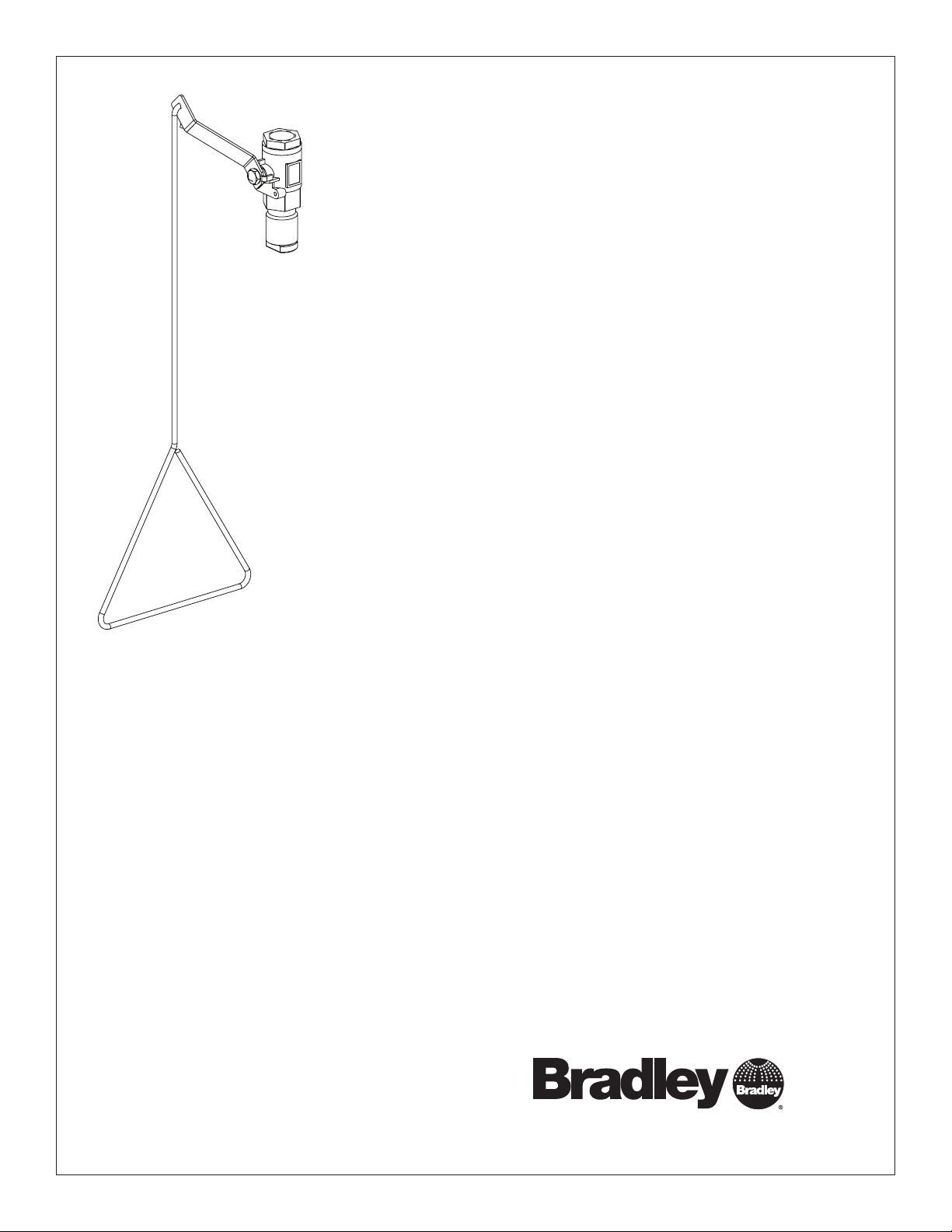
S19-130SS
Stainless Steel Drench Shower
Vertical Supply
Table of Contents
Pre-Installation Information ..........................2
Installation .......................................3
Assembly of Components and Parts List ...............4
215-292 Rev. F; ECN 12-05-016G
© 2012 Bradley
Page 1 of 4 11/12/2012
P.O. Box 309, Menomonee Falls, WI USA 53052-0309
PHONE 800.BRADLEY (800.272.3539) FAX 262.251 5817
bradleycorp.com
Page 2
S19-130SS Installation
IMPORTANT
Installation
R
WI 53051
alls,
HENTLICH ZU
WEEK
WÖC
P.O. Box 309, Menomonee F
DAIRE
e(s) each week and sign
UNIT EACH
y malfunctions immediatel
hentlich im
TEST THIS
hrift. Jeglic
DIESES GERÄT 1ST
ESSAI HEBDOMA
Test-operate valv
Report an
Ventil(e) wöc
t immédiatement.
durch Untersc
Test le fonctionnement des v
signe en bas. S'il y à quelqu
un rappor
Date
Datum
Date
114-051
PRÜFEN.
Testbetrieb prüfen,
he Störung sofor
Signed
Unterschrift
below.
bestätigt
t melden.
y.
alves chaque semaine et
e chose qui ne v
Date Signed
Signe
THIS
SIDE
UP
a pas fait
Signed
Signed
Date
Date
P.O. BOX 309, MENOMONEE FALLS, WI 53052-0309 USA
TEL: 1-800-BRADLEY FAX: (262-251-5817)
http://www.bradleycorp.com
Packing List
•
•
•
•
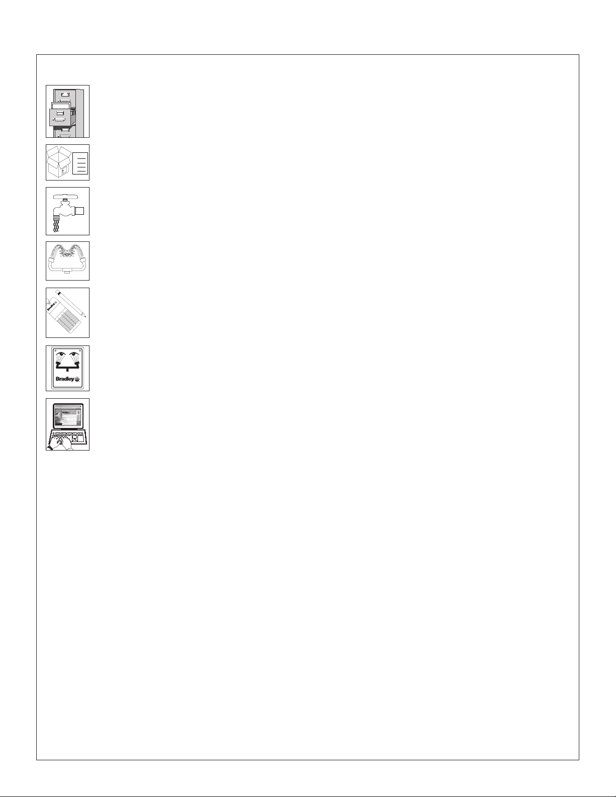
Read this installation manual completely to ensure proper installation, then file it with the owner
or maintenance department. Compliance and conformity to drain requirements and other local
codes and ordinances is the responsibility of the installer.
Separate parts from packaging and make sure all parts are accounted for before discarding
any packaging material. If any parts are missing, do not begin installation until you obtain the
missing parts.
Flush the water supply lines before beginning installation and after installation is complete. Test
the unit for leaks and adequate water flow. Main water supply to the eyewash should be “ON” at
all times. Provisions shall be made to prevent unauthorized shutoff.
The ANSI Z358.1 standard requires an uninterrupted supply of flushing fluid. Bradley plumbed
emergency fixtures require a minimum of 30 PSI (0.21 MPa) flowing pressure. Flushing fluid
should be tepid per ANSI Z358.1.
The inspection and testing results of this equipment should be recorded weekly to verify proper
operation. This equipment should be inspected annually to ensure compliance with ANSI
Z358.1.
Workers who may come in contact with potentially hazardous materials should be trained
regarding the placement and proper operation of emergency equipment per ANSI Z358.1.
For questions regarding the operation or installation of this product, visit www.bradleycorp.com
or call 1-800-BRADLEY.
Product warranties and service parts information may also be found under ”Products” on our
web site at www.bradleycorp.com.
2
11/12/2012 Bradley • 215-292 Rev. F; ECN 12-05-016G
Page 3

Installation S19-130SS
Installation
Supplies Required:
• Pipe sealant
• Piping to 1" NPT water supply inlet
• Adequate supply pipe supports
• Minimum 4" (102 mm) drain to
accommodate 30 gallons (115 liters) per
minute discharge for shower waste
• Sign-mounting hardware
Step 1: Assemble components
1. Assemble components as shown on page 4.
• Apply pipe sealant (supplied by installer)
to all male-threaded pipe joints.
• The bottom edge of the showerhead
should be 84" (2134 mm) from the floor.
7-3/4"
(197mm)
84"
(2134mm)
Suggested
Height to
Floor
6"
(152mm)
Ø 1-1/2"
(38mm)
25-1/2"
(648mm)
Step 2: Connect water supply
IMPORTANT! Do not rely on Bradley’s Drench
Shower to support supply piping.
1. Connect water supply piping to 1" NPT inlet
on unit (piping supplied by installer). Provide
adequate supports (supplied by installer)
for supply pipe using pipe hangers or other
means.
2. Mount the safety sign to the wall using signmounting hardware supplied by installer.
9"
(229mm)
All dimensions assume standard thread
engagement. Variations in manufacturing allow
for +/- ¹⁄₈” (3mm) per threaded joint. To find
the tolerance of a dimension, add the number
of thread joints in between a dimension and
multiply it by ¹⁄₈” (3mm).
Bradley • 215-292 Rev. F; ECN 12-05-016G 11/12/2012
3
Page 4

S19-130SS Installation
Assembly of Components
3
1" NPT
3.2
Supply Inlet
3.1
3.11
4
1
114-050
P.O. BOX 309, MENOMONEE FALLS, WI 53052-0309 USA
TEL: 1-800-BRADLEY FAX: (262-251-5817)
http://www.bradleycorp.com
2
R
P.O. Box 309, Menomonee Falls, WI 53051
TEST THIS UNIT EACH WEEK
DIESES GERÄT 1ST WÖCHENTLICH ZU PRÜFEN.
ESSAI HEBDOMADAIRE
Test-operate valve(s) each week and sign below.
Report any malfunctions immediately.
Ventil(e) wöchentlich im Testbetrieb prüfen, bestätigt
durch Unterschrift. Jegliche Störung sofort melden.
Test le fonctionnement des valves chaque semaine et
signe en bas. S'il y à quelque chose qui ne va pas fait
5
un rapport immédiatement.
Date
Signed
Date Signed
Datum
Unterschrift
Date
Signed
Date
Signe
Date
Signed
Items 3.1–3.2 come preassembled as Item 3.
Parts List
Item Part No. Qty. Description
1 S24-191 1 Stainless Steel Showerhead
2 128-156A 1 Pull Rod, 25½"
3 S30-062 1 1" Stay-Open Ball Valve Assembly
3.1 S27-276 1 1" Ball Valve with Nut
4
11/12/2012 Bradley • 215-292 Rev. F; ECN 12-05-016G
Item Part No. Qty. Description
3.11 161-079 1 Jam Nut Only
3.2 128-143 1 Handle
4 114-050 1 Safety Sign
5 204-421 1 Emergency Inspection Tag
 Loading...