

Bradford White RG140T*N, RG240T*N, RG230S*N, RG230T*N, RG240S*N Service Manual
...
Flammable Vapor Ignition Resistant
Water Heaters
SERVICE
MANUAL
Troubleshooting Guide
and Instructions for Service
(To be performed ONLY by
qualified service providers)
Manual 238-51542-00B REV 10/18
Models Covered
by This Manual:
RG130T*(N,X)
RG140T*(N,X)
RG150T(N,X)
LG250H65*(N,X)
RG230S*(N,X)
RG230T*(N,X)
RG240S*(N,X)
RG240T*(N,X)
RG250H*(N,X)
RG250L*(N,X)
RG250S*(N,X)
RG250T*(N,X)
(*) Denotes Warranty Years
Save this manual for future reference
Introduction 3 - - -
Troubleshooting Chart 4 - - -
Inner Door Gasket Removal, Inspection, and Replacement 9 RG-I
Thermocouple/Thermopile Testing and Replacement 12 RG-II
The Bradford White
®
Page Service Procedure
Pilot Assembly Inspection Cleaning and Replacement 15 RG-III
Piezo Igniter, Electrode Testing and Replacement 16 RG-IV
White Rodgers Gas Valve Testing and Replacement 17 RG-V
Honeywell Gas Control Testing, Disassembly, and Replacement 22 RG-VI
Burner Operation Inspection, Adjustment, Cleaning and Replacement 28 RG-VII
Resettable Thermal Switch Testing and Replacement 31 RG-VIII
ScreenLok
®
Flame Arrestor Cleaning
33 RG-IX
DipTube and Anode Inspection and Replacement 34 RG-X
Generic Parts List 36 - - -
2
2

INTRODUCTION
The Bradford White DEFENDER Safety System
®
The Bradford White DEFENDER Safety System®was designed to resist the ignition
of flammable vapors that can occur outside of the water heater. Use and installation
are nearly identical to previous versions of atmospherically fired and vented water
heaters. A number of exclusive design features are incorporated in the system that
will require additional knowledge on the part of the qualified service provider. The
following information will instruct service professionals on the function, proper
diagnosis and repair of water heaters employing the Bradford White DEFENDER
Safety System.
How the Safety System Works
During normal operation, air for combustion is drawn into the water heater through the
opening in the jacket. This air travels down and around the combustion chamber and
enters through holes in the very bottom of the corrosion-resistant combustion
chamber. The air then travels up through the oriented flame arrestor plate louvers,
where the velocity of the air is increased and its direction altered. The air then mixes
in a normal manner with the supplied gas and is efficiently combusted, producing very
low NOx emissions.
In the case where trace amounts of flammable vapors are present in the air flowing
into the combustion chamber, the vapors are harmlessly ignited by the burner / pilot
flame. If flammable vapors are in sufficient quantity to prevent normal combustion,
the burner/pilot flame is shut down.
Should the flammable vapors continue to the burner, the flame arrestor plate prevents
the flames from traveling backwards and igniting vapors outside of the combustion
chamber. The calibrated, multipurpose thermal switch recognizes this and shuts down
the pilot and main burner. This switch also deactivates the burner and pilot in the
unlikely event of restricted airflow caused by severe lint, dust or oil accumulation on
the arrestor plate.
3
3

White Rodgers Gas Control Troubleshooting Chart
Flammable Vapor Ignition Resistant Water Heaters
Symptom Probable Cause Corrective action
1.
Pilot will not light.
Pilot will not stay lit
when button is
released.
No incoming gas or too low
gas pressure.
2.
Gas control knob set to
wrong position.
3.
Pilot light button not being
fully depressed when
attempting to light pilot.
4.
Pilot orifice or pilot tube is
obstructed or kinked.
5.
Pilot electrode not sparking to
pilot.
6.
Piezo igniter not functioning.
1.
Poor thermocouple
connection at combination
thermostat/gas valve.
2.
Thermocouple not fully
engaged in pilot assembly
bracket.
3.
Pilot flame is not fully
enveloping the thermocouple
“hot” junction.
4.
Weak or defective
thermocouple.
5.
Open ECO on
combination thermostat/
gas valve.
6.
Defective magnet in
combination thermostat/gas
valve.
7.
Resettable thermal switch
has opened.
1.
Turn on gas supply and/or check
line pressure.
2.
Review lighting instruction. Set
combination/thermostat gas valve
to correct position.
3.
Review lighting instruction. Fully
depress pilot lighting button.
4.
Clean, repair or replace.
5.
Verify correct electrode position.
Replace pilot assembly.
6.
Replace piezo igniter.
1.
Check connection at combination
thermostat/gas valve. Proper
tightness should be finger tight
plus ¼ turn.
2.
Inspect thermocouple to ensure
that it is fully engaged into pilot
bracket.
3.
Adjust tip of thermocouple to be
fully engulfed by pilot flame.
4.
Check thermocouple and replace
if necessary.
5.
Check ECO continuity and replace
combination thermostat/gas valve
if necessary.
6.
Check magnet operation and
replace combination
thermostat/gas valve if necessary.
7.
Determine cause of switch
activation. To reset, depress
button on resettable thermal
Service
Procedure
1.
See Service
Procedure RG-V,
Page 12.
2.
See Service
Procedure RG-III,
Page 10.
3.
See Service
Procedure RG-III,
Page 10.
4.
See Service
Procedure RG-IV,
Page 11.
1.
See Service
Procedure RG-II,
Page 8.
2.
See Service
Procedure RG-V,
Page 14.
3.
See Service
Procedure RG-V,
Page 13.
switch located on inner door.
1.
Adjust temperature dial on
combination thermostat/gas
valve.
2.
Check temperature dial
setting on combination
thermostat/gas valve.
3.
Check gas supply and line
pressure.
4.
Check combination
thermostat/gas valve for
proper operation, replace if
necessary.
1.
See installation
and operation
manual.
2.
See Service
Procedure RG-V,
Page 12.
3.
See Service
Procedure RG-V,
Page 12.
Pilot will light but
the main burner
will not come on.
1.
Combination thermostat/gas
valve set too low for desired
water temperature.
2.
Combination
thermostat/gas valve
temperature is satisfied.
3.
Insufficient gas supply or
low gas pressure.
4.
Combination thermostat/gas
valve has wide differential or
is out of calibration.
4
4
White Rodgers Gas Control Troubleshooting Chart
Flammable Vapor Ignition Resistant Water Heaters
Symptom Probable Cause Corrective action
Pilot goes out
periodically (after
heating cycles,
once a day, once
a week etc.)
Not enough hot
water.
1.
Insufficient combustion air
supply.
2.
Incorrect, clogged vent
system/vent terminal or
location.
3.
Inconsistent gas supply or
gas pressure.
4.
Combination thermostat/gas
valve set too low for desired
water temperature.
5.
Cold inlet water temperature
is very cold.
6.
High demand periods.
7.
Incorrectly sized water
heater for application.
8.
Combination thermostat/gas
valve is out of calibration/not
functioning.
9.
Out of spec dip tube is
diluting hot water with cold
water.
1.
Verify adequate combustion air
is available to the unit. Check
and clear Jacket slot openings of
any dirt, dust, restrictions or
other obstructions. Inspect flame
arrestor plate and clean with stiff
bristled brush and/or vacuum to
remove any debris accumulation.
2.
Check venting for proper sizing
and proper operation
3.
Check gas supply and line
pressure.
1.
Check dial on combination
thermostat/gas valve.
2.
Extremely cold water going into
the heater will decrease the
amount of hot water produced. It
may be necessary to temper
incoming water supply.
3.
Adjust high demand usage.
4.
Contact Plumbing professional.
5.
Check combination
thermostat/gas valve for proper
operation, replace if necessary.
6.
Inspect dip tube and replace if
necessary.
Service
Procedure
1.
See Service
Procedure RGVIII, Page 22.
2.
See Service
Procedure RG-V,
Page 14.
1.
See Service
Procedure RG-V,
Page 12.
2.
See Service
Procedure RG-IX,
Page 23.
5
5
g
g
V
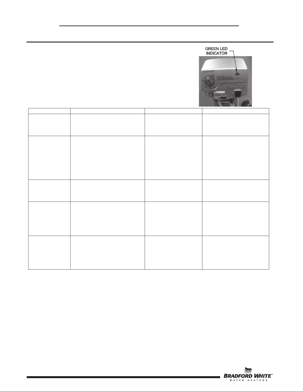
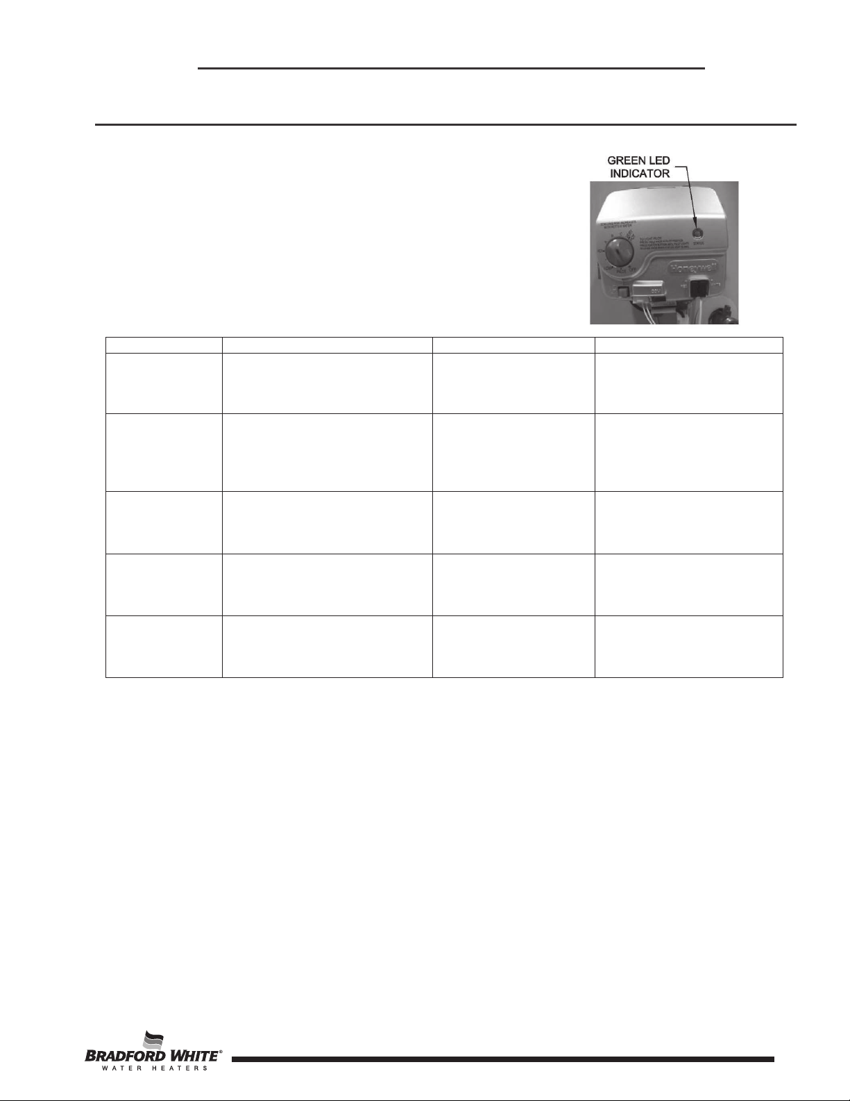
Observe green LED indicator on Gas Control.
Status flash codes are displayed with a three
second pause before repeating. Check and repair
the system as noted in the troubleshooting table
below.
Honeywell V1 Gas Control Troubleshooting Chart
Flammable Vapor Ignition Resistant Water Heaters
LED Status Control Status Probable Cause Service Procedure
If the pilot will not stay lit
None (LED not
on or flashing)
Pilot assembly is not lit
Gas control is not
powered. Light Pilot.
replace pilot assembly. If
problem persists replace
as control.
1.
One flash and
three second
pause
LED on
continuously
(solid)
If setpoint knob is in “PILOT”
position then pilot flame is
detected. Turn setpoint knob
to desired setting.
2.
If the setpoint knob is
already at the desired
setting, the water heater is
satisfied.
Setpoint knob has been recently
turned to the “OFF” position. Wait
until LED goes out before
attemptin
to relight.
1.
Gas control is
powered and waiting
for setpoint knob to
be turned to a water
temperature setting.
2.
Water heater is
satisfied and
operating normally.
Setpoint knob was
turned to “OFF”
position.
Normal operation.
LED will not go out and the
control will function
normally the is lit.
Two flashes
and three
second pause
Three flashes
and three
second pause
6
Weak pilot signal detected.
System will reset when pilot
flame is sufficient.
Insufficient water heating.
System will reset.
1.
Thermopile failure.
2.
Unstable pilot.
3.
Pilot tube block or
restricted.
1.
Thermal sensor out
of calibration.
2.
Faulty gas control.
1.
See service procedure IV
2.
See service procedure II
3.
See service procedure II
Replace gas control.
6
g
y
Observe green LED indicator on Gas Control.
Status flash codes are displayed with a three
second pause before repeating. Check and repair
Honeywell V1 Gas Control Troubleshooting Chart
Flammable Vapor Ignition Resistant Water Heaters
the system as noted in the troubleshooting table
below.
LED Status Control Status Probable Cause Service Procedure
Four flashes
three second
pause
Five flashes
and three
second pause
Six flashes
and three
second pause
Seven flashes
and three
second pause
Eight flashes
and three
second pause
Excessive tank temperature.
System must be reset.
Temperature sensor fault.
Water leak detected by
accessory module
Gas control electronic fault
detected.
Standing pilot remains on while
setpoint knob is in “OFF”
position.
1.
Temperature sensor
out of calibration.
2.
Faulty gas control.
1.
Damage to the
temperature sensor.
2.
Temperature sensor
resistance out of
ran
e.
Excessive amount of
water in drain pan/water
dam.
1.
Control needs to be
reset.
2.
Control is wet or
ph
sically damaged.
Pilot valve stuck in
open position.
Replace gas control
Replace gas control
1. Check T&P valve.
2. Check all water fittings.
3. Pressurize and leak test
tank.
1. Reset gas control
2. Replace gas control.
Replace gas control
7
7

Honeywell V2 Gas Control Troubleshooting Chart
Flammable Vapor Ignition Resistant Water Heaters
Observe colored LED indicator on Gas Control.
Status flash codes are displayed with a three
second pause before repeating. Check and repair
the system as noted in the troubleshooting table
below.
LED Status Control Status Probable Cause Service Procedure
If the pilot will not stay lit
replace pilot assembly. If
problem persists, replace
gas control.
Normal operation.
Normal operation.
1. See service procedure
IV.
2. See service procedure II.
3. See service procedure II.
None (LED not on
or flashing)
One flash every
four seconds
(LED green)
One flash every
second
(LED green)
Two flashes
(LED yellow)
Millivolt power is not
present. Light pilot.
Not an error. Indicates
pilot is lit and main
burner is off.
Not an error. Indicates
main valve is open and
main burner is lit.
Low thermopile voltage;
main valve not turned
ON.
Gas valve is functioning normally.
Gas valve is not powered. Light
pilot.
You can now turn the know to a
desired setpoint temperature
None. Control will automatically
shut main burner off when water
temperature reaches the setpoint
temperature.
Check thermopile and its
connections. Check pilot flame.
Check the valves and the water
temperature sensor. Reduce the
Four flashes
(LED red)
Temperature cut-out
limit reached.
water temperature setpoint.
Thoroughly check
out main valve operation and water
Replace gas control
temperature control before walking
away.
Check water temperature sensor
Five flashes
(LED red)
Water temperature
sensor failure.
and its connection for open
circuits, shorts, or differences in
resistance between the two sensor
Replace gas control
elements.
1. Check T&P valve.
Six flashes
(LED red)
Solid ON
(LED red)
8
Tank leakage detected
by accessory module.
Not an error-indicates
that the control is in
OFF mode.
Control recovers after receiving
message from accessory module.
None; wait until LED turns off if
you want to restart system.
2. Check all water fittings.
3. Pressurize and leak test
tank.
LED will go out and the
control will function normally
the pilot is lit.
8
Inner Door Removal Procedure
)
SERVICE PROCEDURE RG-I
Inner Door/Gasket Removal,
Inspection, and Replacement
Step 1.
Rotate knob of the combination
thermostat/gas valve to the “OFF” position.
Step 2.
Step 3.
Remove outer jacket burner access door.
Inner Door Removal.
a) Disconnect resettable thermal switch wire leads
(leading from gas control/gas valve).
b) Remove (2) hex drive screws from right side inner door.
c) Remove (2) hex drive screws from flange section of inner door.
d) Remove (2) hex drive screws from left side inner door.
e
Remove inner door and inspect per step 4.
Step 4. Fully inspect inner door gaskets for the following:
>Tears
>Missing material
>Cracks
>Other imperfections that will inhibit proper seal
>Gasket adhesion to inner door
>Material left on combustion chamber (around opening)
>Dirt or debris
If the gasket is not affected by any of the above, gasket replacement is not required. If replacement
is required, proceed to Inner Door Gasket Replacement Procedure.
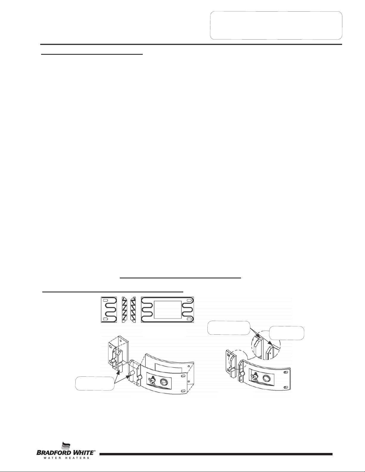
Inner Door Gasket Replacement Procedure
RECOMMENDED
PATTERN FOR RTV
SEALANT
PLACE FLANGE
SECTIONS FIRST
EXPANDED
VIEW
GASKET OVERLAP
MUST BE AS
SHOWN ±1/32"
VIEW WITH
GASKETS IN
PLACE
ENLARGED
VIEW OF
FLANGE AREA
9
9
SERVICE PROCEDURE RG-I
Inner Door/Gasket Removal,
Inspection, and Replacement
Installation of Inner Door with Gasket
Step 5.
Step 6.
Step 7.
Clean any residual gasket residue or other
debris from combustion chamber surface
before installing the inner door/gasket
assembly.
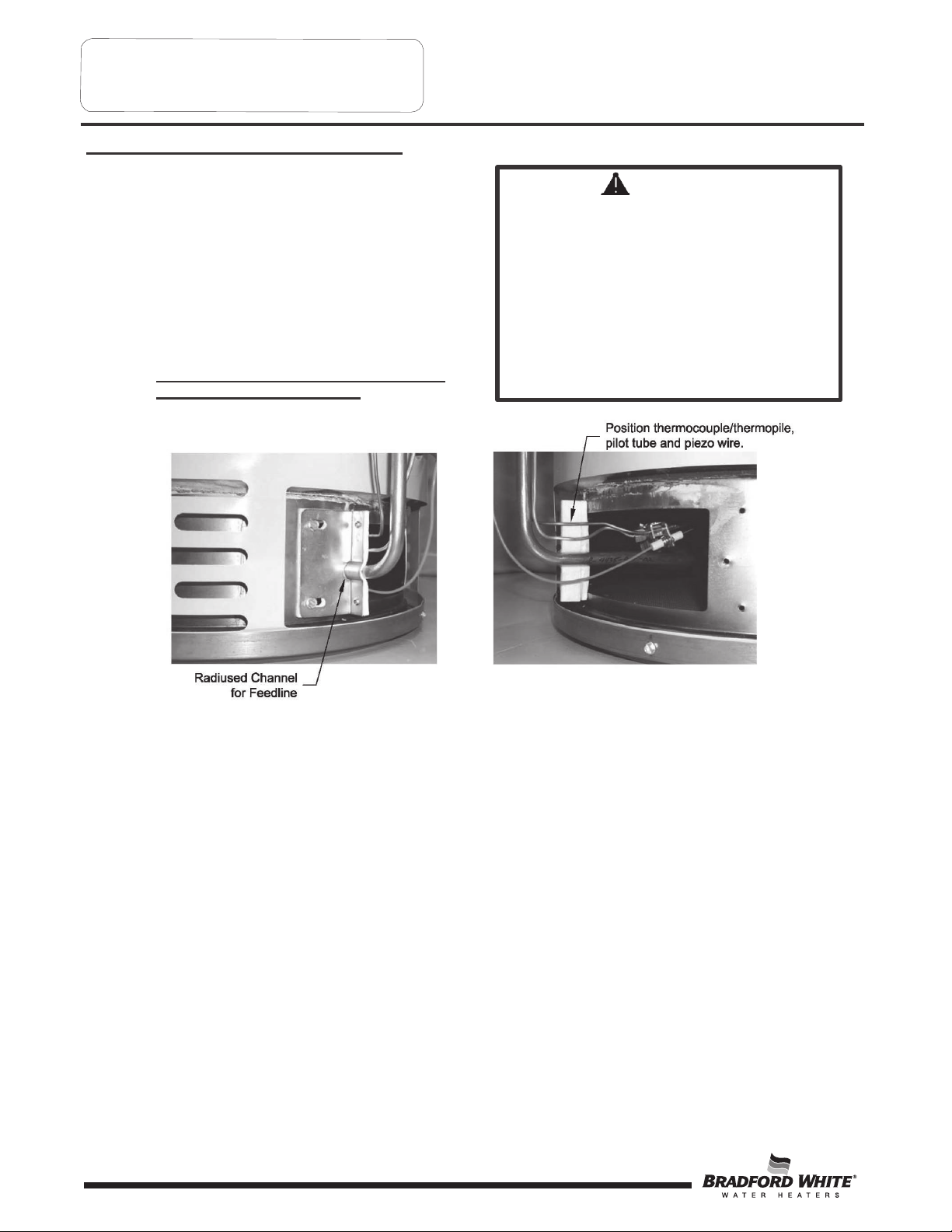
Place the left side inner door into position
first. Firmly position the radiused channel of
the inner door around the feedline. Using the
(2) hex drive screws from step 3d, secure left
side inner door in place
DO NOT OVER TIGHTEN SCREWS.
Position thermocouple, pilot tube and Piezo
wire against left side inner door flange gasket.
DO NOT ROUTE THROUGH RADIUSED
CHANNEL WITH FEEDLINE.
WARNING
Stripped fastener connections may allow
for seal breach of inner door. A seal
breach may result in a fire or explosion
causing property damage, personal injury
or death. Do not over tighten screws in
steps 8, 10 and 11.
If a fastener connection is stripped,
contact the manufacturer listed on the
water heater rating plate.
10
10
SERVICE PROCEDURE RG-I
Inner Door/Gasket Removal, Inspection
Replacement and Reinstallation
Step 8.
Step 9.
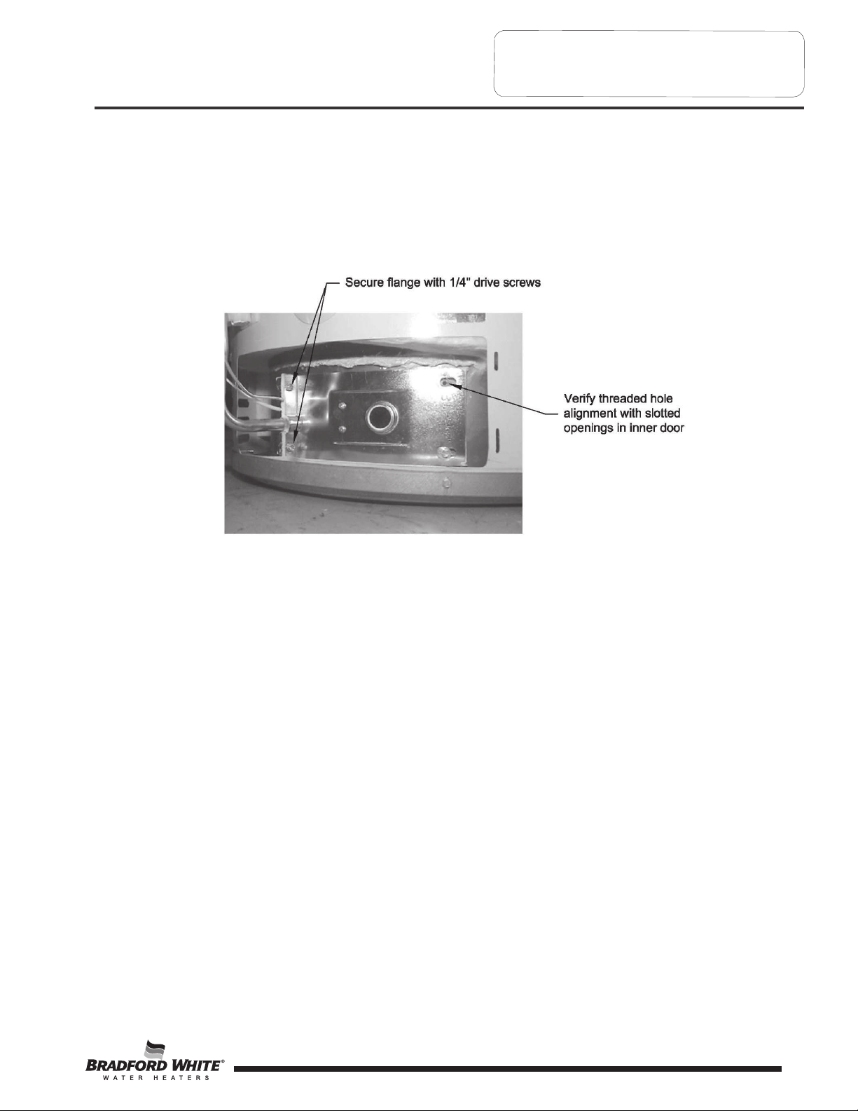
Firmly place right side inner door flange against the left side inner door flange and secure with (2)
hex drive screws from step 3c. DO NOT OVER TIGHTEN SCREWS.
Align right side inner door to combustion chamber and verify the fastener holes of the combustion
chamber are aligned with the right side inner door slotted opening. Verify seal integrity around
combustion opening. Secure right side inner door using (2) hex drive screws from step 3b.
DO NOT OVER TIGHTEN SCREWS. Verify both left and right sides of the inner door are properly
positioned and sealed against the combustion chamber.
Step 10.
Step 11.
Step 12.
Reconnect lead wires from combination thermostat/gas valve to resettable thermal switch (See
photo in step 3). Note, wire terminations are interchangeable with either resettable thermal switch
connections.
Replace outer jacket burner access door.
To resume operation, follow the instructions located on th e lighting instruction label or the lighting
instructions located in the installation and operation manual.
11
11

SERVICE PROCEDURE RG-II
Thermocouple/Thermopile Testing and
Replacement
CLOSED CIRCUIT THERMOCOUPLE TESTING (White Rodgers Control)
Step 1.
Closed circuit testing is the preferred method for testing thermocouple. Following the lighting
instruction label on the heater, proceed to light the pilot and allow to operate for three minutes. If
the pilot will not stay lit, hold the pilot button (located on the combination thermostat/gas valve)
down during this test.
Step 2.
Using a multimeter capable of measuring millivolts, connect one lead
using an alligator clip to the copper sheath of the thermocouple, use the second lead of the
multimeter to probe the top terminal located at the back of the combination thermostat/gas valve.
Step 3.
If meter reads 10 mv or higher, the thermocouple is OK. If reading is below 10 mv,
replace the thermocouple.
12
12
 Loading...