

Bradford White RE2H50, RE2H80 User Manual
Bradford White Heat Pump Water Heater RE2H50, RE2H80
IMPORTANT SAFETY NOTICE
This information is intended for use by individuals
possessing adequate background of electrical,
electronic and mechanical experience. Any attempt to
repair a major appliance may result in personal injury
and property damage. The manufacturer or seller
cannot be responsible for the interpretation of this
information, nor can it assume any liability in connection
with its use. This quick reference guide is provided for
information purposes only and does not replace, modify
or change in any manner the Owner’s Manual and
Installation Instructions.
DISCONNECT POWER BEFORE SERVICING
IMPORTANT- RECONNECT ALL GROUNDING
DEVICES
All parts of this appliance capable of conducting
electrical current are grounded. If grounding wires,
screws, straps, clips, nuts or washers used to complete
a path to ground are removed for service, they must
be returned to their original condition and properly
fastened.
SPECIFICATIONS
Capacity................................................50/80 US gal
Tank Max Working Pressure
........................150 PSI
Water Temperature Set Point Range ..100F - 140F
Electrical
........................... 240/208VAC 60 Hz 1-PH
Circuit Breaker
..............................................30 Amp
Upper Element Wattage
...........................4500/3380
Lower Element Wattage
...........................4000/3004
REFRIGERATION SYSTEM
Compressor .................................................... 500 W
Refrigerant Charge (R134a)
..................29.1/30.9 oz
(50Gal/80Gal)
Compressor LRA
........................................... 14.0A
Compressor RLA
........................................... 2.56A
Typical High Side Pressure (70°F amb)
.... 210-280
PSIA
Typical Low Side Pressure (70°F amb)
55-65 PSIA
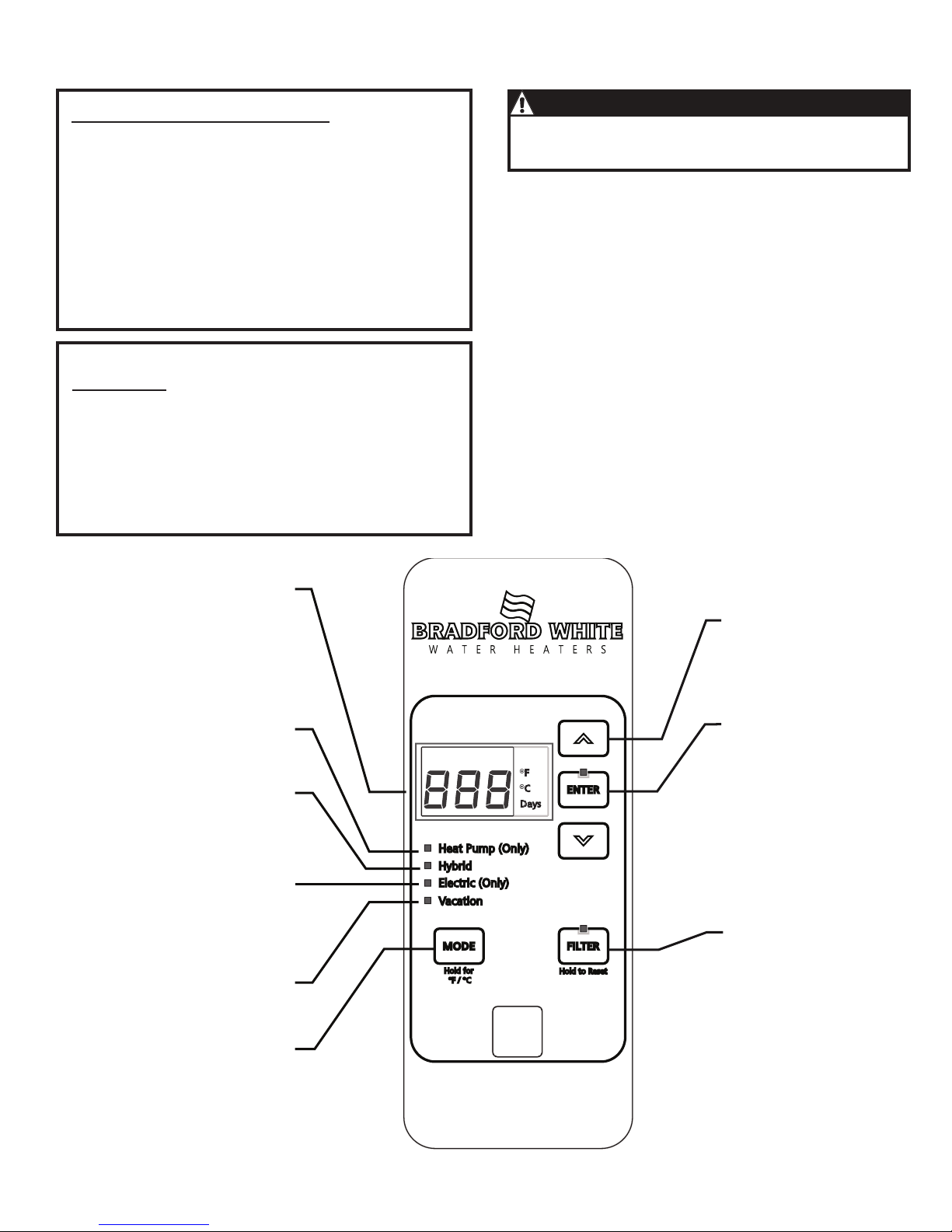
Heat Pump
(Only)
Utilizes heat pump only.
Hybrid
Utilizes the heat pump and
electric heating elements.
Electric
(Only)
Utilizes electric elements
only. Stops the fan, the
heat pump and the flow of
cool air.
Vacation
Use this mode for periods
away from home.
Mode
Press this button to toggle
through the various heating
modes. Press and hold to
switch between ºF and ºC.
Display
Displays the current
temperature or the number
of days for vacation mode.
To display setpoint if display
has gone blank, press any
button.
Arrow Pad
Use the up and down
arrows to manually change
the water temperature, or to
select days for Vacation Mode.
Enter
Press to confirm selections.
Filter
The red LED indicates that
the filter needs cleaning.
Press and hold to reset.
T2 Tank Sensor
T3b Evaporator
Outlet Sensor
T4 Compressor
Outlet Sensor
T3a Evaporator
Inlet Sensor
T5 Ambient Air
Sensor
Condensate
Overflow Senso
r
Double wall heat exchanger, suitable for potable water
connection.
CAUTION
238-52395-00 02/18
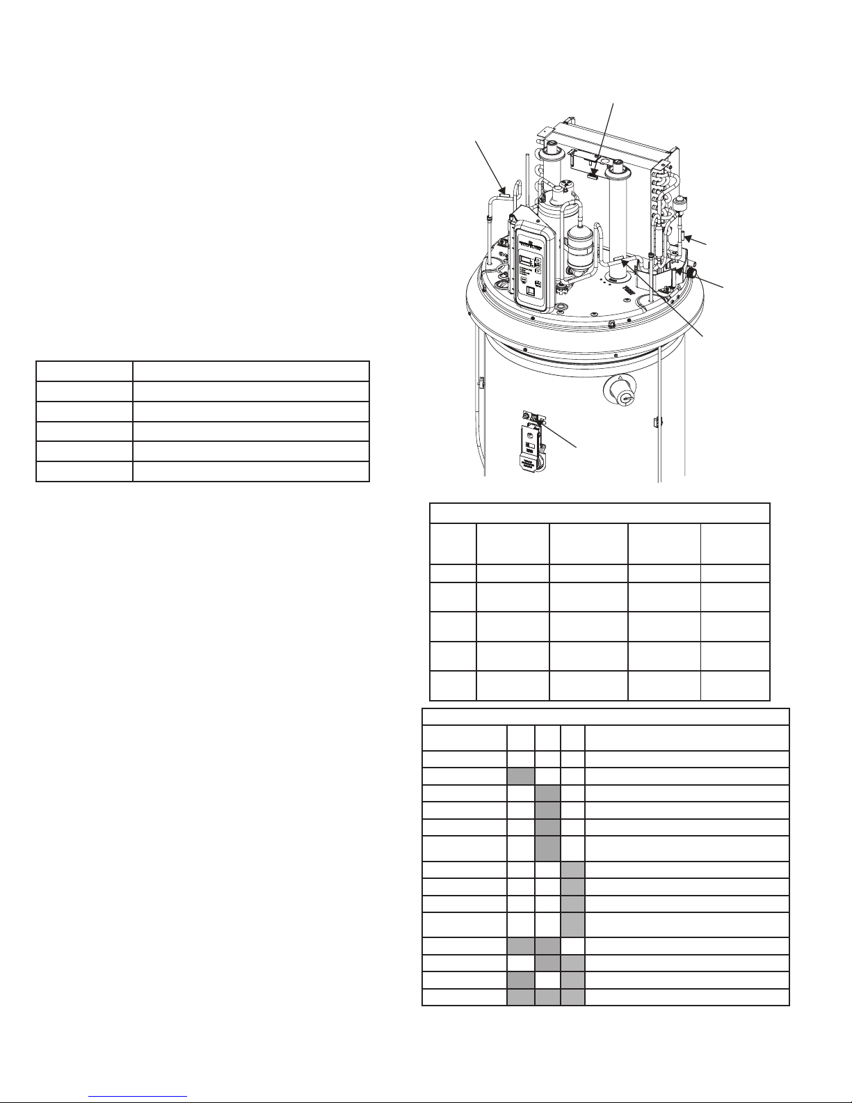
Temperature Sensors
Sensor Description
(wire color)
Normal
temperature
Range
Resistance
range in ohms
Resistance at
77º F
T2 Tank (white) 30º F-160º F 34K-1.75K 10K
T3a Evaporator
Inlet (red)
15º F-130º F 57K-3K 10K
T3b Evaporator
Outlet (white)
15º F-130º F 57K-3K 10K
T4 Compressor
Outlet (blue)
30º F-250º F 188K-3K 55K
T5
Ambient (yellow)
15º F-130º F 57K-3K 10K
SERVICE MODE
The Service Mode can be accessed by pressing and holding the UP
Arrow and Enter buttons simultaneously for 5 seconds. You will first
hear a single beep when pressing the buttons, then a two-tone sound
indicating the action was successful. A moment later, you will see
the first display of the thermistor T2 alternating with its temperature
displayed in the units selected (degrees F or C). The Service Mode
will time out after 15 minutes of button inactivity.
Five functions are available in Service Mode: View Thermistors,
Heating Component Status and Control, View Faults and Counters,
Personality, and Software Revision. You may switch from one function
to another by pressing the Mode button. The operating mode LED will
illuminate to indicate which service mode is selected. An explanation
of the five functions follows:
View Thermistor (Hidden LED) - Each of the 5 thermistors can be
monitored for the temperature they sense. The thermistor designation
appears on the display and alternates with the temperature in degrees
of the units selected - Fahrenheit or Celsius. Pressing the Down
Arrow button switches the display to the next thermistor in the list.
The following table shows the thermistors’ designations and their
function in the unit.
Designation Function
T2 Tank (Water) Temperature
T3a Evaporator Inlet Temperature
T3b Evaporator Outlet Temperature
T4 Compressor Discharge Temperature
T5 Ambient Air Temperature
Heating Component Status and Control, EEV Operation (Heat
Pump (Only) LED) - This function displays the status (on/off) for
each of the heating components - Lower Element, Upper Element,
Compressor (with fan), and Fan - and allows you to turn it on or off.
The first component is the Lower electric element (LE). On status is
signified by a 1 and off is 0. Pressing the Down Arrow button switches
to the Upper Element (UE). Pressing Down Arrow again switches to
the Compressor (with fan) (Co). Pressing the Down Arrow once more
switches to the fan (Fn) . Only one component can be on at one time.
The electric elements will only stay on for 5 minutes without refreshing
by pressing any button on the front panel. The compressor timeout
is 10 minutes. Press the Down Arrow button again to check EEV
Operation. The position will be displayed. Press the Enter button to
open the EEV in increments of 10, from 80 to 450. After reaching
450, pressing Enter will close the valve in increments of 10.
View Faults and Counters (Hybrid LED) - The control counts the
number of times a fault is recorded. A fault code is not displayed until
the number of counts in the fault table (refer to page 2) has been
reached. For example, if the upper element fails to draw current each
time the control energizes the upper element, the count will increase
by 1. However, if the element responds normally, the count will
decrement by 1.
The View Faults and Counters function displays any fault codes in the
system. Pressing the Down Arrow takes you to the next fault code, if
any. If no fault codes are active, “- - -” is displayed. Pressing the Filter
button switches the display to the fault counters. The displayed fault
code alternates with its count value. For example, if the thermistor
T3a has registered 3 failures, its value will be 3 and the display will
alternate between “F5” and “3”.
To clear all fault codes and fault counters, press and hold the Enter
button for 5 seconds and listen for the beep.
Personality (Electric (Only) LED)- This function allows the user to
verify that the correct parameter set has been programmed into the
control board (refer to Personality Table on page 2). The Personality
allows the software to properly control the heating system. The
Personality of the water heater cannot be changed, except by
replacing the control board.
Software Revision (Vacation LED) - This function allows the user
to view the software revision that is programmed into the control. If
the software revision is not correct, the correct revision should be
uploaded.
Exiting Service Mode - To exit Service Mode without waiting for
15 minute timeout, press and hold the Up Arrow and Down Arrow
simultaneously for 5 seconds and listen for two beeps.
T2 Tank Sensor
T3b Evaporator
Outlet Sensor
T4 Compressor
Outlet Sensor
T3a Evaporator
Inlet Sensor
T5 Ambient Air
Sensor
Condensate
Overflow Senso
r
PASS/FAIL COMPONENT OPERATION
Selected Mode SS LE UE Temporary Mode (if component failure is
detected)
Any P P P Runs in selected mode
Any F P P Electric (Only) mode
Hybrid P F P Hybrid Mode (but uses SS when LE is called for)
Electric (Only) P F P Electric (Only) Mode (UE only)
Heat Pump (Only) P F P Heat Pump (Only) mode
High Demand/Boost P F P High Demand/Boost (but uses SS when LE is called
for)
Hybrid P P F Control uses SS and LE based on demand algorithm
Electric (Only) P P F LE Only Mode
Heat Pump (Only) P P F Heat Pump (Only) Mode
High Demand/Boost P P F High Demand/Boost (but uses LE when UE called
for)
Any F F P Electric (Only) Mode (UE only)
Any P F F Heat Pump (Only) Mode
Any F P F LE Only Mode
Any F F F Electric (Only) Mode, displays 1 fault codes
SS = Sealed System
LE = Lower Element
UE= Upper Element
238-52395-00 02/18
Printed in USA
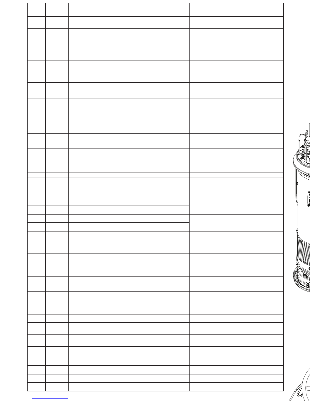
Electronic Expansion Valve (EEV)
This valve replaces the capillary tube typically used in
refrigeration appliances. The EEV meters the flow of liquid
refrigerant entering the evaporator at the rate that matches the
amount of refrigerant being boiled off in the evaporator (gas).
the valve also maintains the proper “superheat” (T3b-T3a).
+
Superheat is the temperature of a gas above the boiling point
of the liquid.
FAN SHROUD
CONDENSER COIL
(Non-replaceable)
Ω
L1
L2
Fault
Code
Displayed
Fault Counts
Before Code
Displayed
Condition Check
FC**
10
Control checks to ensure evaporator is free of frost. Continuously veries
that T3a sensor (evaporator inlet temperature) is greater than 20F after 30
minutes of run time.
Probable refrigerant leak. Find and Repair.
Check T3a sensor mounting, wiring and resistance.
Check EEV wiring at control, coil placement, and operation.
Fd**
10
Control checks to ensure evaporator superheat
+
is OK (controlled by EEV).
Continuously veries the temperature difference between T3a sensor (evap
inlet temp) and T3b sensor (evap outlet temp) is greater than 5F after 30
mins of run time. Control also veries that T3a is greater than 10F less than
T5 ambient sensor.
Possible refrigerant leak. Check sealed system for leak.
Check that lter is clean. Check T3a, T3b and T5 sensor
mounting, wiring and resistance.
Check EEV wiring at control, coil placement, and operation.
FE**
10
Control checks to ensure the compressor discharge temperature never
exceeds 240F. Continuously veries that T4 sensor (compressor outlet
temperature) is less than 240F every minute of run time.
Possible refrigerant leak. Check sealed system for leak.
Check T4 sensor mounting, wiring and resistance.
Check EEV wiring at control, coil placement, and operation.
FF**
10
Control checks to ensure the Electronic Expansion Valve (EEV) is operating
properly and valve rotation is within range.
Probable refrigerant leak. Find and Repair.
Check EEV wiring at control, placement of EEV coil on
EEV valve body, and operation. Conrm audible pulse of
valve homing sequence at power restart.
Check T3a and T3b sensors mounting, wiring and
resistance.
FG 10
Control checks to ensure Ambient temperature is within an acceptable range
of 35ºF < [T5 ambient] <120ºF before starting the heat pump. If not, the unit
will switch to Electric (Only) Mode for that heating cycle only.
NO fault code is shown on the display.
No failure is assumed, but this information is provided for
completeness.
FI** 10
Control checks to ensure evaporator superheat
+
is <20ºF AND the EEV
position is <450 after 30 minutes of run time. If outside these limits, this
provides an early indication of a refrigerant leak. (Note: Target superheat is
generally 10ºF, and EEV generally operates at a position much lower than
450.)
Probable refrigerant leak. Find and Repair.
Check T3a, T3b, T5 sensor mounting, wiring and resistance.
Check EEV wiring at control, coil placement, and operation.
FJ 10
Control checks to ensure that the AC current draw is <= 20.5A while the
compressor and lower heating element are both enabled. If current draw is
>20.5A, the compressor will be disabled.
Check lower heating element rated wattage. Element
wattage is stamped on the heating element terminal block.
Correct wattage can be found on the water heater’s rating
plate.
FL 10
Control checks to ensure that T3a and T3b evaporator inlet and outlet
temperatures are within 2.5ºF of the T5 ambient temperature 20
minutes after defrost begins.
Check airow: fan operation, dirty lter, dirty evaporator.
Check T3a, T3b, T5 sensor mounting, wiring and resistance. Check EEV wiring at control, coil placement, and
operation.
F2
1
T2 tank temperature sensor failure Just before compressor starts, control
checks T2 sensor is within 30F - 170F temperature range.
Check T2 sensor mounting, wiring and resistance.
Use service mode to monitor T2 sensor temperature.
If T2 sensor checks OK, control assembly may have failed.
F3
10
Compressor failure. Control energizes compressor, but current sensor
detects no current ow.
Check compressor run capacitor.
Check compressor, overloads, relay and wiring.
Use service mode to manually cycle compressor on/off.
F4 10 Fan Failure Check fan, wiring, and control connection.
F5
10
T3a sensor (evap inlet temperature) failure. The control detects the thermistor output is at or nearly shorted or open circuit.
Check respective temperature sensor mounting, wiring to
control and resistance.
Use service mode to monitor sensor temperature.
If temperature sensor checks OK, control assembly may
have failed.
F6
10
T3b sensor (evap outlet temperature) failure. The control detects the thermistor output is at or nearly shorted or open circuit.
F7
10
T4 sensor (compressor outlet) failure. The control detects the thermistor
output is at or nearly shorted or open circuit.
F8
10
T5 sensor (ambient temperature) failure. The control detects the thermistor
output is at or nearly shorted or open circuit.
F9 10
Lower heating element failure. Control energizes lower element, but cur
-
rent sensor detects no current ow.
Check respective heating element and wiring connections
at element and control.
Use service mode to cycle element and check current
draw. Control assembly may have failed.
F10 10
Upper heating element failure. Control energizes Upper element, but cur-
rent sensor detects no current ow.
F11 1
Dry Tank fault. Control checks to ensure that the T2 tank temperature
sensor has not risen more than 5ºF during the rst 22 minutes after the unit
is powered on. (The compressor is engaged for 20 minutes after a 2 minute
wait for the system to allow the high and low side pressures to equalize.)
After 1 failed Dry Tank test, “F11” is displayed. After 5 failed tests, an audible
alarm will sound.
Check to ensure the tank is full of water. If full:
Check T2 sensor mounting, wiring and resistance.
Use service mode to monitor T2 sensor temperature.
If T2 checks OK, control assembly may have failed.
bAd linE
(F12)
1
The voltage is too low at power-up. The control monitors the input line voltage1 minute after power-up, and if the voltage is below 155V, the fault code
will be displayed.
Check electrical supply line connections. Voltage should
measure within +10/-15% of either 208 or 240 VAC,
depending upon power supply. Badline counts stored in
“F12” and can be monitored via the Control when placed in
diagnostics mode.Check heating elements are not shorted
to ground.
F13
1
Stuck Key fault. This indicates there is a button on the front panel that is
stuck down. This button is inoperable. Other buttons work normally. If the
button becomes free, the fault code will clear by itself.
Check to see if all buttons are operable.
Ensure control board is fully snapped into control housing.
If board is fully seated, control assembly has failed.
DirtyFilter**
(F14)
5
Filter LED is on, and audible alarm is sounding. Filter is too dirty to enable
proper function of unit. Number of “Dirty Filter” counts are stored in the
“F14” code and can be monitored via the Control when it is placed in Diagnostics Mode. The evaporator is operating at a colder
temperature than the ambient temperature as measured by T5.
Check to ensure Filter is clean. Filter cleaning instructions
are found in the owner’s manual.
Repeated dirty lter alarms that do not resolve by cleaning
are an indication of a sealed system leak. Find and repair
AND ash software to version 4.21 or later, or replace
control.
F15 10
DataFlash fault. The microcontroller has detected a problem in the DataFlash (permanent memory storage).
Control assembly may have failed.
F18 10
Current transformer miswired. F3, F9, and F10 fault codes have all
occurred during the same heating cycle.
Check that red L2 wire is through the CT201 current
transformer on the board. If it is, board needs to be
replaced
F19 10
Low line voltage during compressor operation. Sagging voltage occurs
over time, not at startup like a fault F12- bAd linE.
Check incoming line voltage is within +10/-15% of either
208 or 240 VAC, depending upon power supply.
Check heating elements are not shorted to ground.
F20 10
Condensate drain pan port blocked. Water heater will only operate in
Electric (Only) mode until the drain port is cleared and the sensor
is no longer in contact with water.
Check main drain on condensate drain pan. Unblock if
necessary. Check that the sensor is in the correct position
in the drain pan, on the screw post near the main drain
port. Ensure drain ttings do not reduce diameter at the
drain pan port and cause water to build up in pan.
F21 1
Application Update Failure. A problem occurred while updating the control
application.
Cycle power and try to complete the update again. If prob-
lems persist, reash software or replace the control board.
F22 1
Parametric Data Update Failure. A problem occurred while updating
parametric data.
Cycle power and try to complete the update again. If prob-
lems persist, reash software or replace the control board.
F23 10
Micro A/D Failure. The control has detected a microcontroller input port has
failed.
The control needs to be replaced.
* on some models ** Technicians use TB01-16
238-52395-00 02/18
 Loading...