

Bradford White RE2H50S*-1NCWT Series, RE2H80T*-1NCWT Series Quick Manual
Quick Guide
RE
2H50S*-1NCWT
RE2H80T*-1NCWT
Heat Pump Water Heater
WATER HEATER SAFETY INFORMATION
This is the safety alert symbol. This symbol alerts you to potential hazards that can kill or hurt you and others. All safety
messages will follow the safety alert symbol and the word “DANGER”, “WARNING”, or “CAUTION”. These words are defined as:
DANGER
Indicates a hazardous situation which, if not avoided, will result in death or serious injury.
WARNING
Indicates a hazardous situation which, if not avoided, could result in death or serious injury.
CAUTION
Indicates a hazardous situation which, if not avoided, could result in minor or moderate injury.
IMPORTANT SAFETY INSTRUCTIONS
When using electrical appliances basic safety precautions should be followed, including the following:
WARNING
Risk of Fire - DO NOT store or use gasoline or other flammable vapors and liquids in the vicinity of this or any other appliance.
Keep rags and other combustibles away.
If the water heater has been subjected to flood, fire, or physical damage, turn off power and water to the water heater.
Do not operate the water heater again until it has been thoroughly checked by qualified service personnel.
READ ALL INSTRUCTIONS BEFORE USING.
Safety Precautions
A. Do turn off power to water heater if it has been subjected to overheating, fire, flood or physical damage.
B. Do Not turn on water heater unless it is filled with water.
C. Do Not turn on water heater if cold water supply shut-off valve is closed.
NOTE: Flammable vapors may be drawn by air currents from surrounding areas to the water heater.
D. If there is any difficulty in understanding or following the Operating Instructions or the Care and Cleaning section, it is recommended
that a qualified person or serviceman perform the work.
CAUTION
Risk of Fire - Hydrogen gas can be produced in a hot water system served by this water heater that has not been used for a long
period of time (generally two weeks or more). HYDROGEN GAS IS EXTREMELY FLAMMABLE!! To dissipate such gas and to reduce risk
of injury, it is recommended that the hot water faucet be opened for several minutes at the kitchen sink before using any electrical
appliance connected to the hot water system. If hydrogen is present, there will be an unusual sound such as air escaping through the
pipe as the water begins to flow. Do not smoke or use an open flame near the faucet at the time it is open.
SAVE THESE INSTRUCTIONS
238-52324-00 02/18
IMPORTANT SAFETY INSTRUCTIONS.
!
READ ALL INSTRUCTIONS BEFORE USING.
WATER TEMPERATURE ADJUSTMENT
Safety and energy conservation are factors to be considered
when selecting the water temperature setting via the water
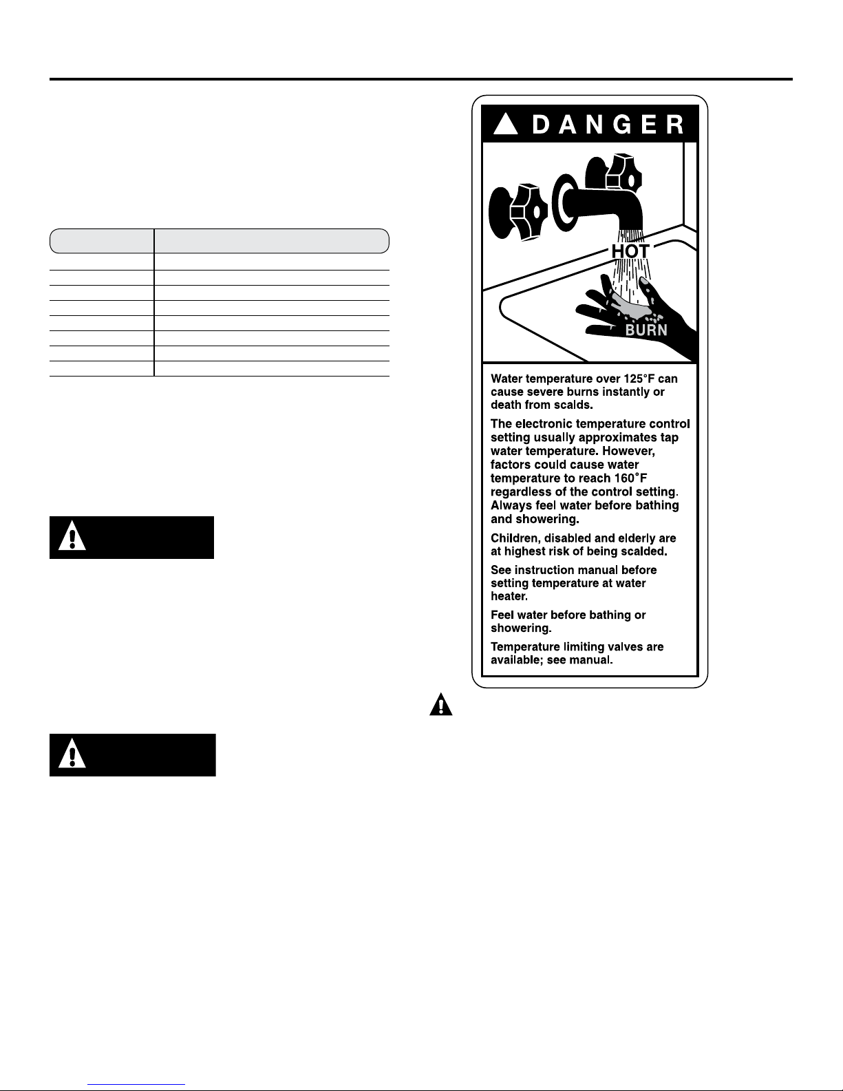
heater’s user interface. Water temperatures above 125°F can
cause severe burns or death from scalding. Be sure to read and
follow the warnings outlined on the label pictured below. This
label is also located on the water heater near the top of the tank.
Time/Temperature Relationship in Scalds
Temperature Time to Produce a Serious Burn
120°F (49°C) More than 5 minutes
125°F (52°C) 1-1/2 to 2 minutes
130°F (54°C) About 30 seconds
135°F (57°C) About 10 seconds
140°F (60°C) Less than 5 seconds
145°F (63°C) Less than 3 seconds
150°F (66°C) About 1-1/2 seconds
155°F (68°C) About 1 second
Table courtesy of Shriners Burn Institute
The chart shown above may be used as a guide in determining
the proper water temperature for your home.
Thermostat has been set at the factory to 120°F (49°C) to reduce
the risk of scald injury.
NOTE: Households with small children, disabled or elderly
persons may require a 120°F (49°C) or lower thermostat setting
to prevent contact with “HOT” water.
DANGER
There is a Hot Water SCALD
Potential if the control water
temperature is set too high.
Safety Controls
The water heater is equipped with a temperature-limiting control
(TCO) that is located above the heating element in contact with
the tank surface. If for any reason the water temperature becomes
excessively high, the temperature-limiting control (TCO) breaks
the power circuit to the heating element. Once the control opens,
it must be reset manually. Resetting of the temperature limiting
controls should be done by a qualified service technician.
CAUTION
condition must be investigated by a qualified service technician
and corrective action must be taken before placing the water
heater in service again.To reset the temperature-limiting
control:
1. Turn off the power to the water heater.
2. Remove the jacket access panel(s) and insulation.
The thermostat protective cover should not be removed.
3. Press the red RESET button.
4. Replace the insulation and jacket access panel(s) before
turning on the power to the water heater.
The cause of the high temperature
FOR INSTALLATIONS
IN THE STATE OF CALIFORNIA
California Law requires that residential water heaters must
be braced, anchored or strapped to resist falling or horizontal
displacement due to earthquake motions. For residential
water heaters up to 52 gallon (236.4 L) capacity, a brochure
with generic earthquake bracing instructions can be obtained
from: Office of the State Architect, 400 P Street, Sacramento,
CA 95814 or you may call 916.324.5315 or ask a water heater
dealer.
Applicable local codes shall always govern installation. For
residential water heaters of a capacity greater than 52
gallons (236.4 L) consult the local building jurisdiction for
acceptable bracing procedures.
California Proposition 65 Warning: This product contains
chemicals known to the State of California to cause cancer,
birth defects or other reproductive harm.
SAVE THESE INSTRUCTIONS
2
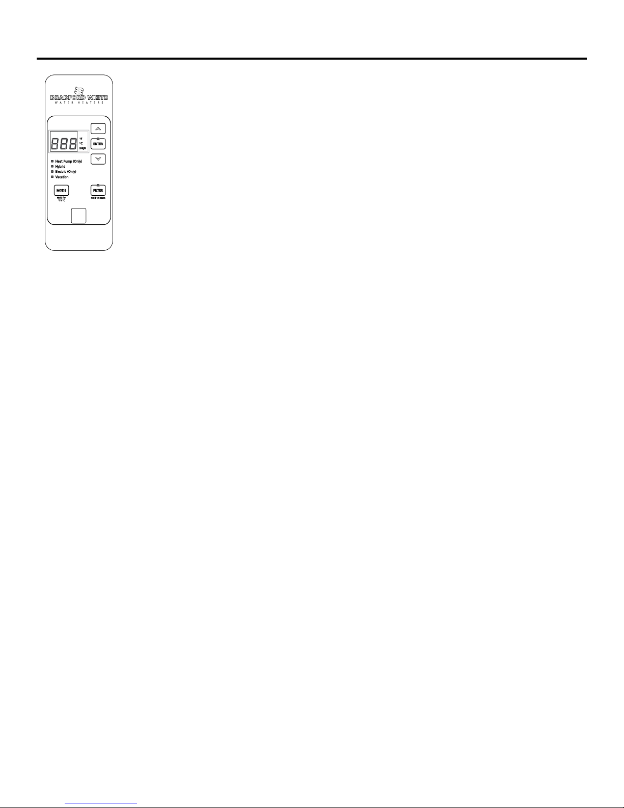
About the control panel.
This water heater defaults to the Hybrid
operating mode. Available modes are listed
below and can be selected using the MODE
button.
Heat Pump (Only) Mode—RECOMMENDED
FOR MAXIMUM SAVINGS
Heat Pump is the most energy-efficient mode
for this water heater. It takes heat from the
surrounding air to heat the water. The time
it takes to heat the water is longer in this
mode, so it may not be sufficient if you have
a high-demand situation such as a large
household or company.
Hybrid Mode
Hybrid mode combines the energy
efficiency of Heat Pump (Only) with the recovery speed
and power of the Electric (Only) mode in most water usage
situations. Hybrid mode will allow the unit to perform like
a standard electric water heater while providing significant
energy savings.
Cold Climate Eciency setting (CCE)
For installations where ambient conditions may be considered
cold, an available Cold Climate Eciency (CCE) setting can be
activated in the control to achieve additional energy savings
in Hybrid mode.
In some regions, rebates may be available which require
this setting to be used to qualify [e.g. compliance with NEEA
Northern Climate specication Tier 3 requirements]. Check
with your local utility for available rebates and requirements.
The CCE setting is activated by pressing and holding the
DOWN arrow and the Filter button at the same time for 5
seconds. “CCE” will display temporarily when CCE settings
have been activated [“dUC” may display on some models]. To
deactivate the CCE setting, press and hold the same buttons
[DOWN arrow & Filter button] at the same time for 5 seconds.
“Std” will display temporarily when CCE settings have been
deactivated and the water heater has returned to normal
operation of the selected mode.
A ducting kit is also available for use with your heat pump
water heater if desired. [see www.BradfordWhite.com for
details].
Ducting kits may be installed to achieve directed ow of
inlet and outlet air for heat pump operation independent of
whether the CCE setting is activated. Ducting kits may also
be installed to allow water heater installation in rooms less
than 700cu.ft. or without louvered doors, as specied in the
installation instructions.
NOTE: Energy Guide unit performance, energy consumption
and savings are based on non-ducted installations in Hybrid
mode operation at a temperature setting of
135°F (57°C).
Electric (Only) Mode
This mode uses only the upper and lower heating resistance
elements to heat the water, stopping the cool air discharge
during heat pump operation. The time it takes to heat the
water is less in this mode, but it is the LEAST energy-ecient
mode.
Follow these steps to set Electric (Only) mode:
1. Select Electric (Only) mode using the Mode button.
2. Input the total days to remain in Electric (Only) mode using
the UP arrow, or remain in Electric (Only) mode indenitely
by selecting “---”.
3. Press ENTER
At the end of the selected time period, the unit will switch
back to the previously selected more energy-ecient mode.
NOTE: In this mode the green LED light will ash after 48
hours as an indication that the unti is not operating in the
most energy ecient mode. The unit will continue to operate
in this mode and does not indicate an operating issue.
NOTE: With the CCE setting active, Electric (Only) mode can
be set for 1-7 days.
Vacation
This feature is used when you will be away from the home for an
extended period of time and hot water is not needed. In this mode,
the unit will drop the water temperature down to 50ºF (10°C) and
will use the most efficient heating mode to conserve energy while
the heater is sitting idle. The unit will automatically resume heating
one day before your return, so that hot water will be available.
For example if you will be gone 14 days, follow these steps:
1. Select VACATION by using the Mode button
2. Input total days you will be gone (in this example, 14) by pressing
the UP arrow button (the default is 7 days)
3. Press ENTER.
The unit will drop the water temperature down to 50ºF (10°C) for
one day less than you will be gone (in this example, for 13 days). At
the end of the day before you return (in this example, the 13th day),
it will automatically return to the previous operating mode and
heat the water to the original temperature setting so hot water is
available upon your return.
To access any of these modes:
1. Press the MODE button on the control to the desired operating
mode.
2. The green light will be illuminated on the chosen mode.
To Adjust the Temperature
Follow these steps:
1. Press the UP or DOWN arrow on the control panel key pad to
desired temperature.
2. Press ENTER to accept the new setting.
Note: To change between °F and °C, press and hold MODE.
In winter months, the water heater will take longer to heat
incoming water to a preset point due to the colder temperature of
the incoming water.
3
Care and cleaning.
DRAINING THE WATER HEATER
2. Turn o the cold water supply.
CAUTION: Risk of Shock - Shut off power to
the water heater before draining water.
DANGER: Risk of Scald - Before manually
operating the relief valve, make certain no one will be exposed
to the hot water released by the valve. The water drained from
the tank may be hot enough to present a scald hazard and
should be directed to a suitable drain to prevent injury or
damage.
To drain the water heater, follow these steps:
1. Attach a garden hose to the drain valve located at the
bottom of the unit and direct that hose to a drain.
EXTENDED SHUTDOWN PERIODS OR VACATIONS EXCEEDING VACATION MODE OPTIONS
If the water heater is to remain idle for an extended period of
time, the power and water to the appliance should be turned
off and the water heater drained to conserve energy and
prevent a buildup of dangerous hydrogen gas. This unit has
no power button, power can only be shut off at the circuit
breaker or disconnect switch.
If the water heater has an anode depletion sensing feature
(some models) and the water heater cannot be drained, it is
recommended to leave the power turned on with the water
heater in vacation mode to ensure that the feature will
continue to operate properly while still conserving energy.
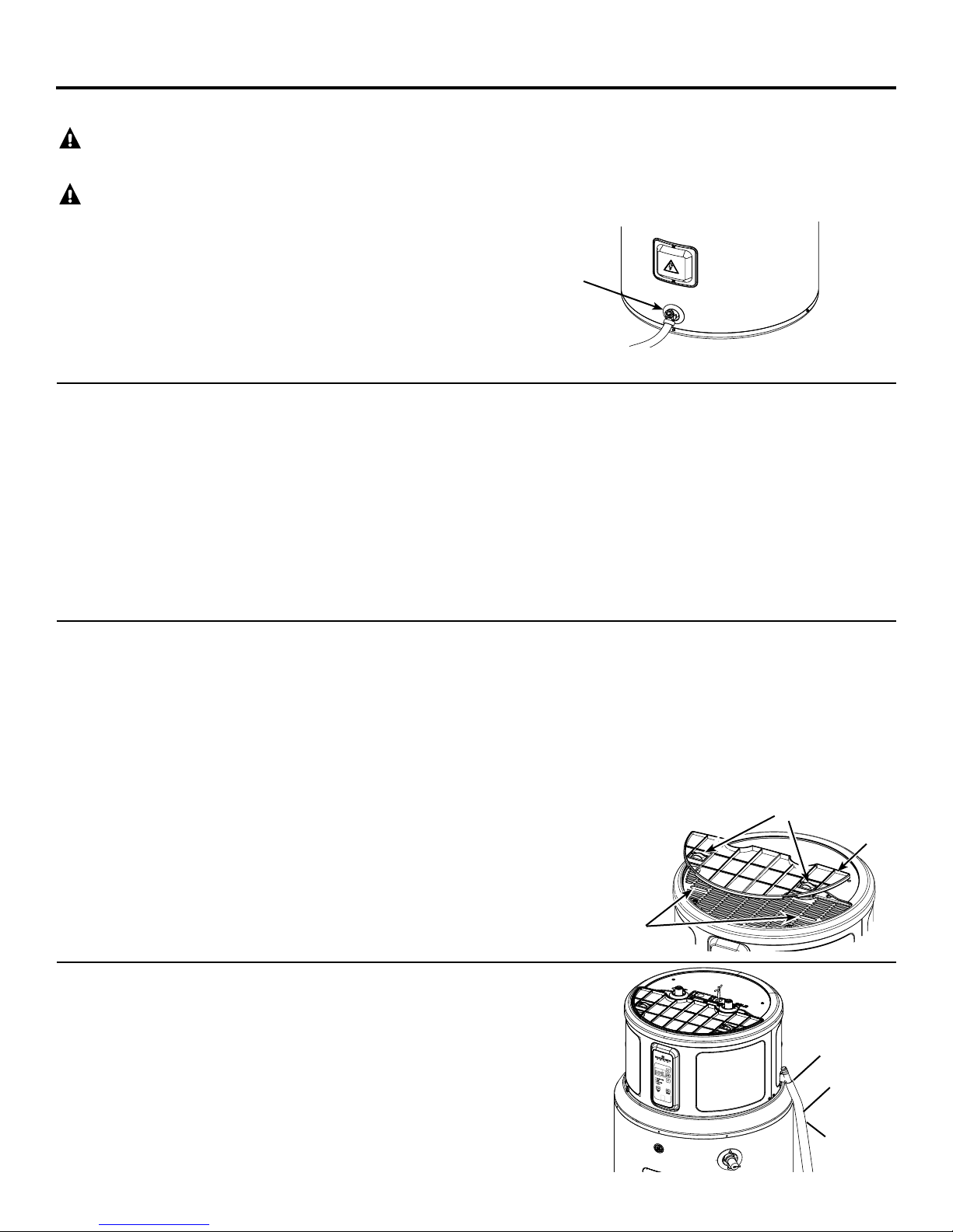
3. Admit air to the tank by opening a hot water faucet or
lifting the handle on the relief valve
4. Open the drain valve with a at screwdriver.
Note: See page 15 for product schematic.
Use a flat slot
screwdriver to
turn valve.
The water heater and piping should be drained if they might
be subjected to freezing temperatures.
After a long shutdown period, the water heater’s operation
and controls should be checked by qualified service
personnel. Make certain the water heater is completely filled
again before placing it in operation.
NOTE: Refer to the Hydrogen Gas Caution in the Operating
Instructions (see page 3).
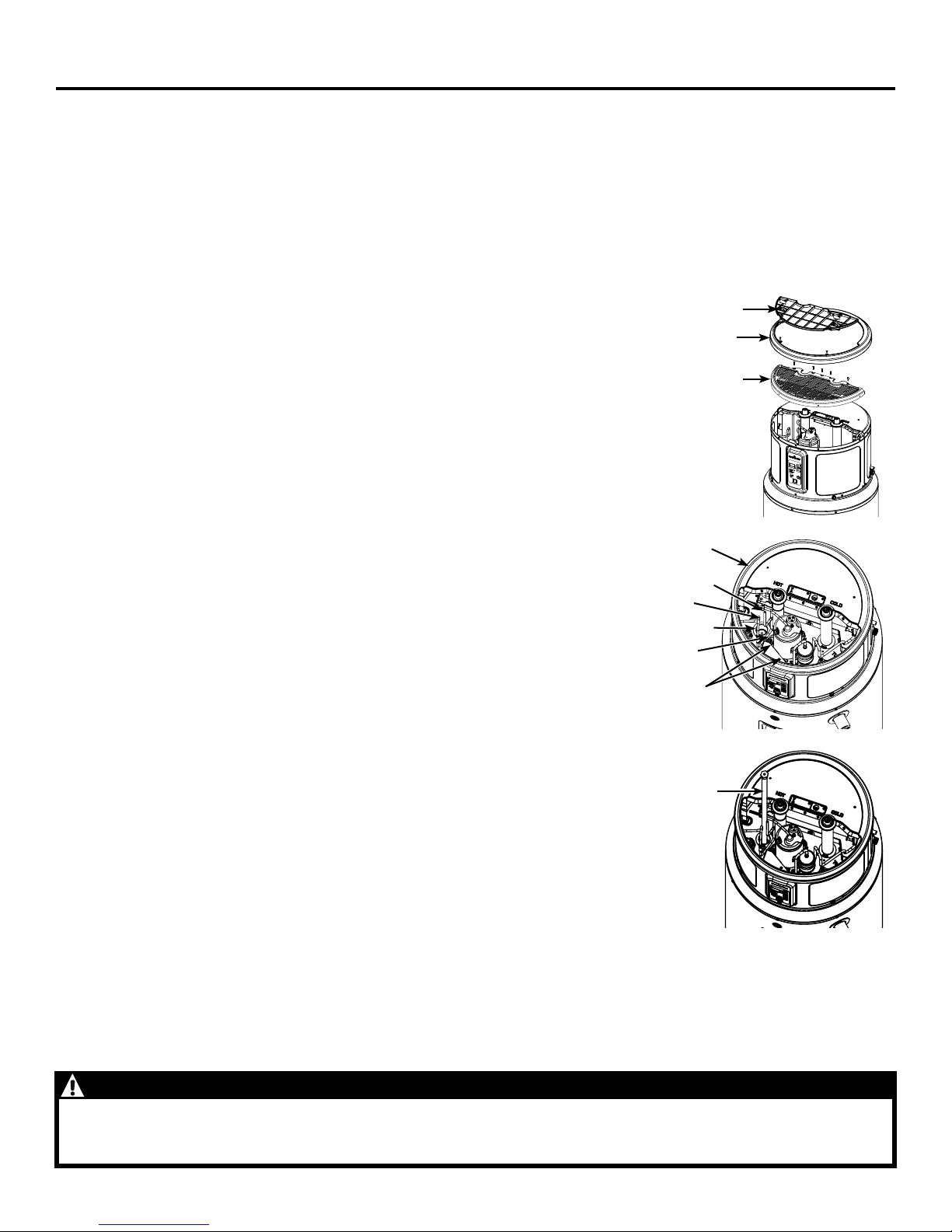
CLEANING THE FILTER
In the Hybrid, Heat Pump and High Demand/Boost modes, the heater
moves air through the system and out the back of the unit. The filter
is in place to protect the evaporator from dirt and dust.
A clean air filter is important to get the highest efficiency. Occasionally this filter will need to be cleaned (minimum once per year). When
the filter requires cleaning, the Red light above the Filter button will be
illuminated and an audible beep will sound.
NOTE: If the filter gets too dirty, the unit will automatically switch to
Electric/Standard mode and energy savings will be lost.
Leave the power on. Remove the filter from
the top of the unit. Squeeze two tabs and lift to remove the air filter.
Once it has been removed, the filter can be vacuumed or wiped clean
with a damp cloth or rinsed with warm water.
Once the filter has been cleaned and dried, it can be replaced by
aligning it into the slots in the top of the unit and pushing it down into
place.
CLEARING THE CONDENSATION DRAIN TUBE
The main drain is intended to carry all condensate away. If it is
clogged, the heat pump will stop operating, the display will show
F20, and an alarm will sound. Press any button to silence the
alarm, then clear the condensate drain by removing any drain
lines and connections, and clearing debris. Reattach drain lines
and connections, then allow the water heater to run.
Periodically inspect the drain lines and clear any debris that may
have collected in the lines.
After the clean filter has been reinstalled, press and hold the FILTER
button. If a heating cycle is on when the filter fault is reset, it will continue in electric mode to finish the cycle. After that, it will automatically revert to the mode it was in prior to being switched.
IMPORTANT: Filter must be cleaned when the alarm is displayed. A
dirty filter will make the system work harder and result in a reduction
of efficiency and possible damage to the system. In order to get the
best energy efficiency available, make sure your filter is clean.
Tabs
Filter
Slots
See Installation
Instructions for
more information.
Overow
Main drain line
Direct the
main drain
tube into a
drain
4
Anode Rod Maintenance and Service.
ANODE ROD
The anode rod should be removed from the water heater’s tank and
inspected once every 3 years service, and replaced when more than
6” (15.2 cm) of core wire is exposed at either end of the rod. For more
information contact us at www.bradfordwhite.com.
NOTE: Artificially softened water requires that the anode rod be
inspected annually.
Due to shock hazard and to prevent accidental water leaks, this
inspection should be done by a qualified servicer or plumber, and
requires that the electric power and cold water supply be turned off
before servicing the anode rod.
NOTICE: Do not remove the anode rod from the water heater’s tank
except for inspection and/or replacement, as operation with the
anode rod removed will shorten the life of the glass-lined tank and
will void warranty coverage.
The anode rod consumption and replacement are not covered by
warranty.
Some areas have water conditions that may cause an odor to
develop in the water heater. Aluminum-Zinc alloy replacement rods
are available to address the condition.
Additional information for products with an anode depletion
sensing feature:
When the system indicates that the anode depletion sensing anode
rod is approaching end of life, it is recommended to replace it. To
silence the alarm, press the Anode button once. Call Bradford White
Tech Service to order or to replace the anode depletion sensing
anode rod. After replacing, reset the Anode alarm by pressing and
holding the Anode button for 10 seconds until the control beeps and
the LED above the button turns off.
If an Aluminum-Zinc anode rod is installed to address a water odor
condition, the anode depletion sensing feature must be disabled.
Upon power-up after installing an Aluminum-Zinc anode rod, the
control will sound an alarm. To quiet the alarm and disable the
feature, first press the Anode button once to silence the alarm, then
press the Anode button 3 times. The control will beep and a message
will scroll on the display confirming that the feature has been
disabled. Annual inspections of the anode rod are recommended
since the water heater will no longer be capable of alerting for a
depleted anode rod. To enable the feature if an anode depletion
sensing anode rod is installed, press the Anode button 3 times. The
control will beep and a message will scroll on the display confirming
that the feature has been enabled.
NOTE: If the water heater has been installed with a device that
periodically cuts power to the water heater, the accuracy of the
anode rod depletion sensing feature may become compromised and
anode rod inspection every 2-3 years is recommended.
If the water heater will be inactive for a long period of time and the
water heater cannot be drained, it is recommended to leave the
power turned on with the water heater in vacation mode to ensure
that the feature will continue to operate properly while still conserving
energy.
NOTE: Refer to the Hydrogen Gas Caution in the Operating
Instructions (see page 1).
Tools needed:
• T20 Torx Screwdriver • Socket Extention 12” long
• Slot Screwdriver • 1-1/16” Socket
• Tape • Socket Wrench
• Softset Sealant • Anode Rod, if needed
To service the Anode Rod:
1. Disconnect power, shut off the water supply, and partially drain
2. Remove the filter, trim ring,
3. Reinstall the trim ring,
4. Remove insulation to
5. Using a 1-1/16”
6. To install the
7. Turn water supply on, open a tap to remove any air in
one or two gallons from the water heater through the lower
drain valve.
and front top cover as
show in Illustration A.
place a protective layer
of tape on sheet metal
edges, as show in
Illustration B.
uncover the anode rod
as show in Illustration
B. Unplug anode wire (on
some models).
Trim Ring
socket and
extension,
unscrew the
anode rod, then
lift out to inspect
as show in
Illustration C.
anode rod, seal
the threads with
soft set sealant,
thread into the port
and using the torque
wrench tighten to
50 ± 5 ft-lbs of
torque. Plug in the
wire for the anode
rod if present.
Reinstall the anode
rod insulation. If an
Aluminum-Zinc or
other non-sensing
anode rod is
installed, the anode depletion sensing feature must be disabled
and the wire end taped (some models).
plumbing system, inspect for leaks, then reassemble the unit
in reverse order as shown in Illustration A, and turn the power
on. Reset the Anode button (some models) by pressing and
holding for 10 seconds to indicate that a new anode depletion
sensing anode rod is installed.
Tape Process
Tube Pinch O
Wires
Anode Rod
Insulation Foam
Wires
Tape Corner
and Edges
Illustration B
Anode Rod
Illustration C
Filter
Trim Ring
Front
Top Cover
Illustration A
CAUTION - IMPORTANT SAFETY NOTICE
This information is intended to use by individuals possessing adequate background of electrical, electronic and mechanical experience. Any attempt to repair a major appliance may result in personal injury and property damage. The manufacturer or seller
cannot be responsible for the interpretation of this information, nor can it assume any liability in connection with its use.
5
Installation
8”
(20.3cm)
LOCATION
The water heater and water lines should be protected from freezing
temperatures and high-corrosive atmospheres. Do not install the water
heater in outdoor, unprotected areas.
CAUTION: Risk of Property Damage -
water heater should not be located in an area where leakage of
The
CATCH PAN INSTALLATION (If required)
NOTE: Auxiliary catch pan MUST conform to local codes.
Catch Pan Kits are available from the store where the water heater was
purchased, a builder store or any water heater distributor. The catch pan
should be 2” (5.1 cm) minimum larger than the Water Heater base diameter.
To prevent corrosion and improve Drain Valve access it is recommended that
the water heater be placed on spacers inside the catch pan.
the tank or connections will result in damage to the area
adjacent to it or to lower floors of the structure. Where such
areas cannot be avoided, it is recommended that a suitable
catch pan, adequately drained, be installed under the water
heater.
NOTE: The heat pump operating range is 35°F to 120°F (2°C to 49°C).
If the ambient temperature is outside of this range, the heat pump
will turn off and the electric elements will be used until the ambient
temperature
returns to within the operating range.
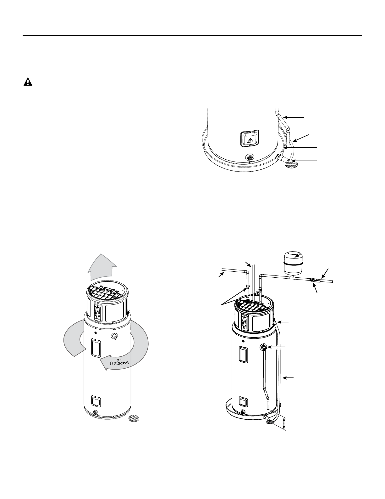
REQUIRED CLEARANCES:
There must be a 7” (17.5 cm) clearance between any object and the rear
and sides of the water heater in the event service is needed. A minimum 8“
(20.3cm) clearance above the water heater to remove the lter for cleaning
and for service access, and clear access to the front of the water heater, is
recommended. Installations that require 6” clearance on the sides or rear of
the water heater for earthquake straps are also acceptable. In these cases,
additional clearance must be provided on the opposite side of the unit to
allow for service access. The hot and cold water plumbing and electrical
connections must not interfere with the removal of the lter.
If a separate ducting kit is purchased, additional space is required above
and to the rear of the water heater for installation. Consult the ducting kit
manual for specific instructions. See www.bradfordwhite.com for details.
THERMAL EXPANSION
If check valve is present on inlet water line, use of a thermal expansion
tank is recommended. Check valves on the inlet water line are referred
to as a "closed system." A closed system can cause the check valve on
the water heater to operate more than intended, causing premature
failure. The suggested method of controlling thermal expansion is to
install an expansion tank in the cold water line between the water
heater and the check valve as shown.
TYPICAL INSTALLATION
To Electrical Junction Box
(use only copper conductors)
Hot water
outlet to
xtures
(suggested)
Relief Valve Drain
Condensate Drain
Catch Pan
Catch Pan
Drain
Thermal
expansion tank
To cold
water supply
Shut-o valve
Union
Model appearance may vary
6
Model appearance may vary
3/4” FNPT tting to
Condensate Drain Pan
Temperature &
Pressure Relief Valve
Condensate Drain
Tube
Relief Valve discharge
6” (15.2 cm) minimum
from the oor
or
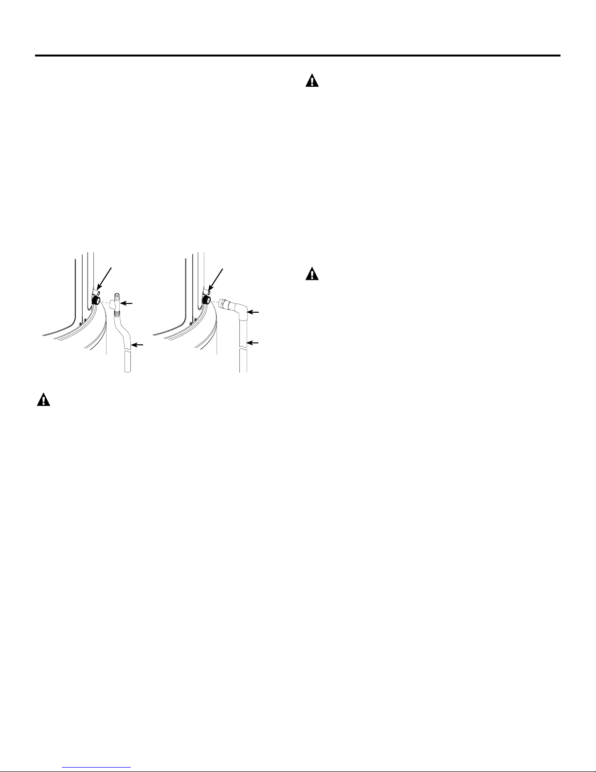
CONDENSATION DRAIN CONNECTION
This unit has a condensate drain; therefore a floor or other drain no
higher than 36” (91.4cm) above the floor must be available in close
proximity to the water heater to allow for the shortest possible drain
line with minimal turns to be installed. Drain must meet state and
local codes. It is important to install a 3/4” FNPT fitting suitable for
either rigid or flexible drain line to the primary drain port coming off
the side of the unit. Diameter reductions from a 3/4” drain line are
not recommended.
Ensure that the rigid or flexible drain line maintains a downward
slope to allow for proper gravity drainage of condensate to the drain
and to allow for proper function of the condensate drain blockage
sensor (see page 12). If no drain is available, then a common
condensate pump with a capacity no less than 1 gallon (3.8L)/day
must be purchased and installed. It is important to route the flexible
or rigid drain line so that the discharge water cannot contact live
electrical parts or cause water damage .
Condensate
Drain Overow
Fitting
Drain
Line
Condensate
Drain Overow
Fitting
Drain
Line
RELIEF VALVE
WARNING: Risk of Unit Damage - The
pressure rating of the relief valve must not exceed 150 PSI (1.03
kPa), the maximum working pressure of the water heater as
marked on the rating plate.
A new combination temperature/pressure-relief valve, complying with
the Standard for Relief Valves and Automatic Gas Shut-Off Devices for
Hot Water Supply Systems, ANSI Z21.22, is supplied and must remain
installed in opening provided and marked for the purpose on the water
heater. No valve of any type should be installed between the relief valve
and the tank. Local codes shall govern the installation of relief valves.
The BTUH rating of the relief valve must not be less than the input rating
of the water heater as indicated on the rating label located on the front
of the heater (1 watt=3.412 BTUH).
Connect the relief valve outlet to a suitable open drain so the discharge
water cannot contact live electrical parts or persons and to eliminate
potential water damage.
Piping used should be of a type approved for hot water distribution. The
discharge line must be no smaller than the outlet of the valve and must
pitch downward from the valve to allow complete drainage (by gravity)
of the relief valve and discharge line. The end of the discharge line should
not be threaded or concealed and should be protected from freezing. No
valve of any type, restriction or reducer coupling should be installed in the
discharge line.
CAUTION:
To reduce the risk of excessive pressures and temperatures in this
water heater, install temperature and pressure protective equipment
required by local codes and no less than a combination temperature
and pressure relief valve certified by a nationally recognized testing
laboratory that maintains periodic inspection of production of listed
equipment or materials, as meeting the requirements for Relief Valves
and Automatic Gas Shutoff Devices for Hot Water Supply Systems,
ANSI Z21.22. This valve must be marked with a maximum set pressure
not to exceed the marked maximum working pressure of the water
heater. Install the valve into an opening provided and marked for this
purpose in the water heater, and orient it or provide tubing so that
any discharge from the valve exits only within 6 inches above, or at
any distance below, the structural floor, and does not contact any live
electrical part. The discharge opening must not be blocked or reduced
in size under any circumstances.
TO FILL THE WATER HEATER
WARNING: Risk of Unit Damage - The tank
must be full of water before heater is turned on. The water
heater warranty does not cover damage or failure resulting
from operation with an empty or partially empty tank.
Make certain the drain valve is completely closed.
Open the shut-off valve in the cold water supply line.
Open each hot water faucet slowly to allow the air to vent from the
water heater and piping.
A steady flow of water from the hot water faucet(s) indicates a full water
heater.
"F11” fault code during installation: If the unit is powered on without a
full tank, the error code “F11” will show in the display. Turn o the power,
ll the tank with water (see above), then turn the power back on.
NOTE: The DRY TANK DETECTION feature on tank is for the aid of installer
and should NOT be used as the primary control to prevent operation with
an empty or partially lled tank. Power should NEVER be applied to the
water heater until installer has veried tank is lled and all air has been
purged from system.
NOTICE:
Do not mis-wire electrical connections. 240V AC or 208AC must be
applied across L1 and L2 wires as shown in ‘Water heater junction
box’ illustration. Failure to do so will VOID the warranty, and can result
in 120V applied to water heater, which may damage the compressor
or other electrical components.
If 4-conductor wire is supplied to the water heater, cap the neutral,
and connect the remaining wires as illustrated.
NOTE REGARDING UTILITY POWER-MANAGEMENT DEVICES
(Sometimes called Peak Load Reduction Switches):
Some power-management switching devices or even some basic
timer switches exist that REDUCE voltage from 240V to 120V during
high-electricity-demand periods. These devices must be removed
from the circuit providing power to the water heater because of the
potential unit damage noted above.
However, switching devices which cut power from 240V to 0V on a
periodic basis are acceptable.
“bAd linE” fault code during installation: If “bAd linE” is shown on
the display, the unit is not receiving the correct voltage as a result of
incorrect wiring. To correct this fault, turn the power o to the unit,
correct the wiring issue, then turn the power back on.
7
Installation
ELECTRICAL CONNECTIONS
A separate branch circuit with copper conductors, overcurrent protective
device and suitable disconnecting means must be provided by a qualified
electrician.
All wiring must conform to local codes or latest edition of National Electrical
Code ANSI/NFPA 70.
The water heater is completely wired to the junction box at the top of the
water heater. An opening for 1/2” electrical fitting is provided for field wiring
connections.
The voltage requirements and wattage load for the water heater are
specified on the rating label on the front of the water heater.
The branch circuit wiring should include either:
1. Metallic conduit or metallic sheathed cable approved for use as a
grounding conductor and installed with fittings approved for the
purpose.
2. Nonmetallic sheathed cable, metallic conduit or metallic sheathed
cable not approved for use as a ground conductor shall include
a separate conductor for grounding. It should be attached to the
ground terminals of the water heater and the electrical distribution
box.
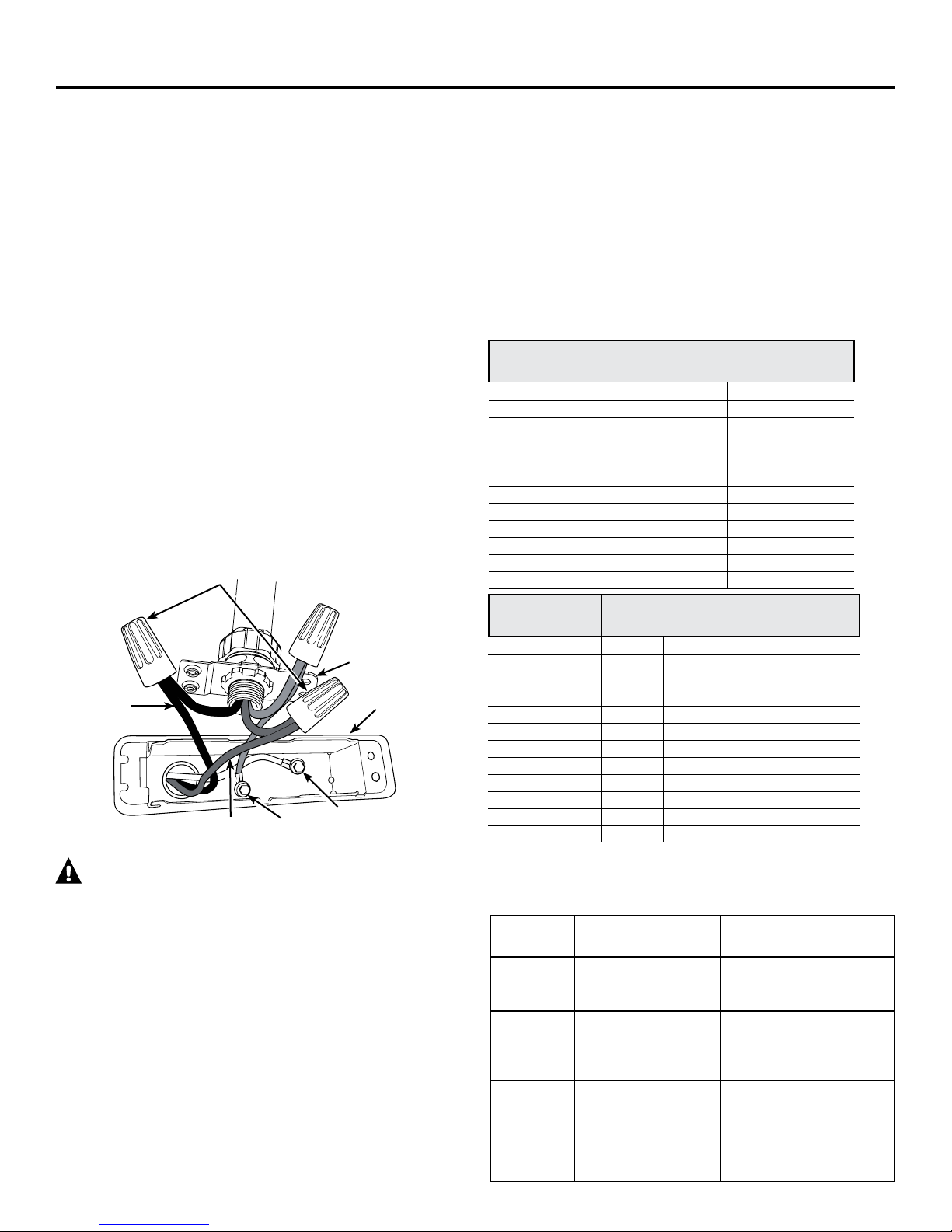
To connect power to the water heater:
1. Turn the power o.
2. Remove the screw/screws holding the junction box top cover.
3. Install L1 to L1, L2 to L2 and ground to the green ground wire
connected to the bottom of the junction box.
NOTE: Install electric connections according to local codes or latest
edition of National Electrical Code ANSI/NFPA 70.
240V
Application of any external insulation, blankets or water pipe insulation
to this water heater will require careful attention to the following:
• Do not cover the temperature and pressure-relief valve.
• Do not cover access panels to the heating elements.
• Do not cover the electrical junction box of the
water heater.
• Do not cover the operating or warning labels attached to the water heater
or attempt to relocate them on the exterior of the insulation blanket.
• Do not block the air inlet/outlets in the top covers or rear of the unit.
NOTE: This guide recommends minimum branch circuit sizing based on
the National Electric Code. Refer to wiring diagrams in this manual for
eld wiring connections.
BRANCH CIRCUIT SIZING GUIDE
Total Water Recommended Over-Current Protection
Heater Wattage (fuse or circuit breaker amperage rating)
208V 240V 277V 480V
3,000 20 20 15 15
4,000 25 25 20 15
4,500 30 25 25 15
5,000 30 30 25 15
5,500 35 30 25 15
6,000 40 35 30 20
8,000 50 45 40 25
9,000 – 50 45 25
10,000 – – 50 30
11,000 – – 50 30
12,000 – – – 35
L1 (Black)
L2 (Red)
House Ground
(Green)
WARNING: Proper ground connection is essential.
The presence of water in the piping and water heater does not
provide sufficient conduction for a ground. Nonmetallic piping,
dielectric unions, flexible connectors, etc., can cause the water
heater to be electrically isolated. Do not disconnect factory
ground.
The manufacturer’s warranty does not cover any damage or defect caused
by installation, attachment or use of any type of energy-saving or other
unapproved devices (other than those authorized by the manufacturer)
into, onto or in conjunction with the water heater. The use of unauthorized
energy-saving devices may shorten the life of the water heater and may
endanger life and property.
The manufacturer disclaims any responsibility for such loss or injury resulting
from the use of such unauthorized devices.
If local codes require external application of insulation blanket kits, the
manufacturer’s instructions included with the kit must be carefully followed.
8
Junction box
cover
Junction box
Factory Ground
Total Water Copper Wire Size AWG Based
Heater Wattage on N.E.C. Table 310-16 (167°F/75°C.)
208V 240V 277V 480V
3,000 12 12 14 14
4,000 10 10 12 14
4,500 10 10 10 14
5,000 10 10 10 14
5,500 8 10 10 14
6,000 8 8 10 12
8,000 8 8 8 10
9,000 – 8 8 10
10,000 – – 8 10
11,000 – – 8 10
12,000 – – – 8
NORMAL STARTUP CONDITIONS:
Once tank is full and power is energized, you may experience the following:
NOTE: Heat Pump operating range is 35°F - 120°F (2°C-49°C).
Elapsed
Time
0 to 2 minutes
2 to 22
minutes
22
minutes
and beyond
HEWH Actions Comments
Unit will go through
self-check and display
countdown
Compressor and fan
turn on
Compressor and fan turn
off, heating elements
turn on. After initial
heat-up, elements turn
off and compressor
turns on.
This 2-minute off-time prevents compressor damage.
This 20-minute period is used
to ensure the tank is full of
water (Dry-fire prevention
algorithm).
The water heater is operat
ing in Hybrid mode. Quickly
provides initial amount of hot
water, then switches to effi
cient heat pump for majority
of heating.
-
-
Troubleshooting…
Before you call for service.... Save time and money! Review the chart below first and you may not need to call for service.
Problem Possible Causes What To do
CAUTION: For your safety, DO NOT attempt repair of electrical wiring, controls, heating elements or other
safety devices. Refer repairs to qualied service personnel.
Water heater makes sounds A fan is used to move air through
Water heater is making the
room cooler
Water dripping down the
outside of the heater
Not enough or not hot water Water temperature may be set
Water is too hot
Rumbling noise Water conditions in your home
The heater is beeping and the
display says F11
The heater is beeping and the
screen says “F17”
The heater is beeping and the
screen says, “FA-F8”
The heater is beeping and the
screen ashes an error code
Hot water has a rotten egg or
sulphur smell
the system
Room is not vented properly or is
too small
Heat is removed from the air to
heat the water
Condensate drain is clogged • Clear out any debris in the drain port on the unit.
Hot/Cold water connections are
not tightened
too low
Hot water usage pattern exceeds
the capability of the water heater in
current mode
Leaking or open hot water faucets
Long runs of exposed pipe, or hot
water piping on outside wall
Not enough clearance to allow air
to circulate for the heater pump
Room size is not appropriate for
water heater
Inadequate wiring • See the Installation Instruction section.
Manual reset limit (TCO) • See the Safety Control section, see page 4.
Water connections to unit re-
versed
Water temperature is set too high
Electric control has failed • Call for service.
caused a buildup of scale or
mineral deposits on the heating
elements
The water heater has not been
lled with water before powering up. Powering up the heater
without water will damage the
electric heaters. The water heater
warranty does not cover damage
or failure resulting from operation
with an empty or partially empty
tank.
The anode rod is not connected
properly and the water heater may
not be protected from corrosion.
There is an issue with the heat
pump system.
There is an issue with the water
heater that requires immediate
attention.
Certain water supplies with high
sulphate content will react with
the anode rod that is present in
all water heaters for corrosion
protection of the tank
• Some amount of fan sound is normal. If you hear an abnormal sound or the sound
level seems unusually loud, then contact service.
• If the room is smaller than 10’ x 10’ x 7’ (3m x 3m x 2.1m) then it must have a louvered door or other means to allow air exchange with surrounding rooms.
• This is normal.
• Tighten the inlet and outlet pipe connections.
• See About the Water Temperature Setting section.
• Change to dierent mode.
• Wait for the water heater to recover after an abnormal demand.
• Make sure all faucets are closed.
• Insulate piping.
• Make sure unit is 7" away from the wall and has 8" clearance above the air lter.
• If room size is less than 10’ x 10’ x 7’ (700 cu. ft.), install louvered door or similar
ventilation.
• Correct piping connections.
• See About the Water Temperature Setting section.
• Remove and clean the heating elements. This should only be done by a qualied
service personnel.
• Fill the tank completely with water. Press ENTER to stop the alarm and then cycle
power when the tank has been lled.
• If the unit has been conrmed to be lled with water, and an F11 code is expe-
rienced, it is possible that the code may be a false indicator due to certain unique
environment conditions encountered during the start up. If the unit is full of water,
turn the breaker off for about 10 minutes to allow the water temperature to
stabilize, then turn the breaker back on. If the F11 code persists, schedule service.
• Check that the tank is lled completely with water.
• If the tank is full of water and the F17 code persists, contact
service.
• The unit will automatically switch to another available mode to ensure you continue to have hot water. Contact service immediately and give them the codes listed on
the display screen.
• The heater may switch to another available heating mode. Contact service immediately. To stop the beeping noise (unless error code F2, F11, F17 or bAd linE) press
either the UP or DOWN arrow button and the alarm will stop and the display will go
back to normal (set temperature).
• The odor can be reduced or eliminated in most water heaters by replacing the
anode rod with less-active material rod. In some cases, an added step of chlorinating
the water heater and all hot water lines may be necessary, contact your local water
professional or plumber for options and instructions. A qualified servicer or plumber
should do this replacement.
9

Notes.
10
 Loading...