

Page 1
Bradford White Heat Pump Water Heater RE2H50, RE2H80
IMPORTANT SAFETY NOTICE
This information is intended for use by individuals
possessing adequate background of electrical,
electronic and mechanical experience. Any attempt to
repair a major appliance may result in personal injury
and property damage. The manufacturer or seller
cannot be responsible for the interpretation of this
information, nor can it assume any liability in connection
with its use. This quick reference guide is provided for
information purposes only and does not replace, modify
or change in any manner the Owner’s Manual and
Installation Instructions.
DISCONNECT POWER BEFORE SERVICING
IMPORTANT- RECONNECT ALL GROUNDING
DEVICES
All parts of this appliance capable of conducting
electrical current are grounded. If grounding wires,
screws, straps, clips, nuts or washers used to complete
a path to ground are removed for service, they must
be returned to their original condition and properly
fastened.
SPECIFICATIONS
Capacity................................................50/80 US gal
Tank Max Working Pressure
........................150 PSI
Water Temperature Set Point Range ..100F - 140F
Electrical
........................... 240/208VAC 60 Hz 1-PH
Circuit Breaker
..............................................30 Amp
Upper Element Wattage
...........................4500/3380
Lower Element Wattage
...........................4000/3004
REFRIGERATION SYSTEM
Compressor .................................................... 500 W
Refrigerant Charge (R134a)
..................29.1/30.9 oz
(50Gal/80Gal)
Compressor LRA
........................................... 14.0A
Compressor RLA
........................................... 2.56A
Typical High Side Pressure (70°F amb)
.... 210-280
PSIA
Typical Low Side Pressure (70°F amb)
55-65 PSIA
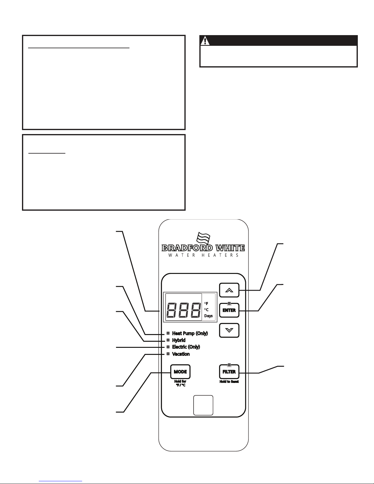
Heat Pump
(Only)
Utilizes heat pump only.
Hybrid
Utilizes the heat pump and
electric heating elements.
Electric
(Only)
Utilizes electric elements
only. Stops the fan, the
heat pump and the flow of
cool air.
Vacation
Use this mode for periods
away from home.
Mode
Press this button to toggle
through the various heating
modes. Press and hold to
switch between ºF and ºC.
Display
Displays the current
temperature or the number
of days for vacation mode.
To display setpoint if display
has gone blank, press any
button.
Arrow Pad
Use the up and down
arrows to manually change
the water temperature, or to
select days for Vacation Mode.
Enter
Press to confirm selections.
Filter
The red LED indicates that
the filter needs cleaning.
Press and hold to reset.
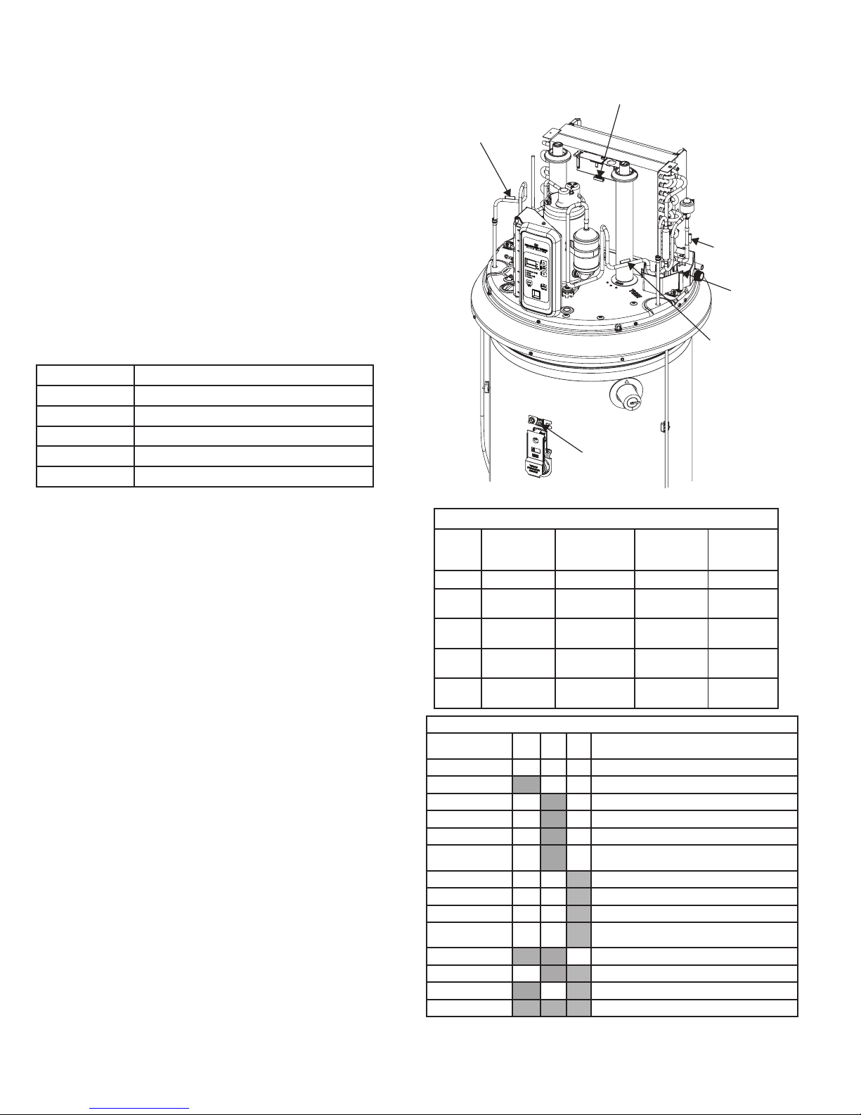
T2 Tank Sensor
T3b Evaporator
Outlet Sensor
T4 Compressor
Outlet Sensor
T3a Evaporator
Inlet Sensor
T5 Ambient Air
Sensor
Condensate
Overflow Senso
r
Double wall heat exchanger, suitable for potable water
connection.
CAUTION
238-52395-00 02/18
Page 2
Temperature Sensors
Sensor Description
(wire color)
Normal
temperature
Range
Resistance
range in ohms
Resistance at
77º F
T2 Tank (white) 30º F-160º F 34K-1.75K 10K
T3a Evaporator
Inlet (red)
15º F-130º F 57K-3K 10K
T3b Evaporator
Outlet (white)
15º F-130º F 57K-3K 10K
T4 Compressor
Outlet (blue)
30º F-250º F 188K-3K 55K
T5
Ambient (yellow)
15º F-130º F 57K-3K 10K
SERVICE MODE
The Service Mode can be accessed by pressing and holding the UP
Arrow and Enter buttons simultaneously for 5 seconds. You will first
hear a single beep when pressing the buttons, then a two-tone sound
indicating the action was successful. A moment later, you will see
the first display of the thermistor T2 alternating with its temperature
displayed in the units selected (degrees F or C). The Service Mode
will time out after 15 minutes of button inactivity.
Five functions are available in Service Mode: View Thermistors,
Heating Component Status and Control, View Faults and Counters,
Personality, and Software Revision. You may switch from one function
to another by pressing the Mode button. The operating mode LED will
illuminate to indicate which service mode is selected. An explanation
of the five functions follows:
View Thermistor (Hidden LED) - Each of the 5 thermistors can be
monitored for the temperature they sense. The thermistor designation
appears on the display and alternates with the temperature in degrees
of the units selected - Fahrenheit or Celsius. Pressing the Down
Arrow button switches the display to the next thermistor in the list.
The following table shows the thermistors’ designations and their
function in the unit.
Designation Function
T2 Tank (Water) Temperature
T3a Evaporator Inlet Temperature
T3b Evaporator Outlet Temperature
T4 Compressor Discharge Temperature
T5 Ambient Air Temperature
Heating Component Status and Control, EEV Operation (Heat
Pump (Only) LED) - This function displays the status (on/off) for
each of the heating components - Lower Element, Upper Element,
Compressor (with fan), and Fan - and allows you to turn it on or off.
The first component is the Lower electric element (LE). On status is
signified by a 1 and off is 0. Pressing the Down Arrow button switches
to the Upper Element (UE). Pressing Down Arrow again switches to
the Compressor (with fan) (Co). Pressing the Down Arrow once more
switches to the fan (Fn) . Only one component can be on at one time.
The electric elements will only stay on for 5 minutes without refreshing
by pressing any button on the front panel. The compressor timeout
is 10 minutes. Press the Down Arrow button again to check EEV
Operation. The position will be displayed. Press the Enter button to
open the EEV in increments of 10, from 80 to 450. After reaching
450, pressing Enter will close the valve in increments of 10.
View Faults and Counters (Hybrid LED) - The control counts the
number of times a fault is recorded. A fault code is not displayed until
the number of counts in the fault table (refer to page 2) has been
reached. For example, if the upper element fails to draw current each
time the control energizes the upper element, the count will increase
by 1. However, if the element responds normally, the count will
decrement by 1.
The View Faults and Counters function displays any fault codes in the
system. Pressing the Down Arrow takes you to the next fault code, if
any. If no fault codes are active, “- - -” is displayed. Pressing the Filter
button switches the display to the fault counters. The displayed fault
code alternates with its count value. For example, if the thermistor
T3a has registered 3 failures, its value will be 3 and the display will
alternate between “F5” and “3”.
To clear all fault codes and fault counters, press and hold the Enter
button for 5 seconds and listen for the beep.
Personality (Electric (Only) LED)- This function allows the user to
verify that the correct parameter set has been programmed into the
control board (refer to Personality Table on page 2). The Personality
allows the software to properly control the heating system. The
Personality of the water heater cannot be changed, except by
replacing the control board.
Software Revision (Vacation LED) - This function allows the user
to view the software revision that is programmed into the control. If
the software revision is not correct, the correct revision should be
uploaded.
Exiting Service Mode - To exit Service Mode without waiting for
15 minute timeout, press and hold the Up Arrow and Down Arrow
simultaneously for 5 seconds and listen for two beeps.
T2 Tank Sensor
T3b Evaporator
Outlet Sensor
T4 Compressor
Outlet Sensor
T3a Evaporator
Inlet Sensor
T5 Ambient Air
Sensor
Condensate
Overflow Senso
r
PASS/FAIL COMPONENT OPERATION
Selected Mode SS LE UE Temporary Mode (if component failure is
detected)
Any P P P Runs in selected mode
Any F P P Electric (Only) mode
Hybrid P F P Hybrid Mode (but uses SS when LE is called for)
Electric (Only) P F P Electric (Only) Mode (UE only)
Heat Pump (Only) P F P Heat Pump (Only) mode
High Demand/Boost P F P High Demand/Boost (but uses SS when LE is called
for)
Hybrid P P F Control uses SS and LE based on demand algorithm
Electric (Only) P P F LE Only Mode
Heat Pump (Only) P P F Heat Pump (Only) Mode
High Demand/Boost P P F High Demand/Boost (but uses LE when UE called
for)
Any F F P Electric (Only) Mode (UE only)
Any P F F Heat Pump (Only) Mode
Any F P F LE Only Mode
Any F F F Electric (Only) Mode, displays 1 fault codes
SS = Sealed System
LE = Lower Element
UE= Upper Element
238-52395-00 02/18
Printed in USA
Page 3
Electronic Expansion Valve (EEV)
This valve replaces the capillary tube typically used in
refrigeration appliances. The EEV meters the flow of liquid
refrigerant entering the evaporator at the rate that matches the
amount of refrigerant being boiled off in the evaporator (gas).
the valve also maintains the proper “superheat” (T3b-T3a).
+
Superheat is the temperature of a gas above the boiling point
of the liquid.
FAN SHROUD
CONDENSER COIL
(Non-replaceable)
Ω
L1
L2
Fault
Code
Displayed
Fault Counts
Before Code
Displayed
Condition Check
FC**
10
Control checks to ensure evaporator is free of frost. Continuously veries
that T3a sensor (evaporator inlet temperature) is greater than 20F after 30
minutes of run time.
Probable refrigerant leak. Find and Repair.
Check T3a sensor mounting, wiring and resistance.
Check EEV wiring at control, coil placement, and operation.
Fd**
10
Control checks to ensure evaporator superheat
+
is OK (controlled by EEV).
Continuously veries the temperature difference between T3a sensor (evap
inlet temp) and T3b sensor (evap outlet temp) is greater than 5F after 30
mins of run time. Control also veries that T3a is greater than 10F less than
T5 ambient sensor.
Possible refrigerant leak. Check sealed system for leak.
Check that lter is clean. Check T3a, T3b and T5 sensor
mounting, wiring and resistance.
Check EEV wiring at control, coil placement, and operation.
FE**
10
Control checks to ensure the compressor discharge temperature never
exceeds 240F. Continuously veries that T4 sensor (compressor outlet
temperature) is less than 240F every minute of run time.
Possible refrigerant leak. Check sealed system for leak.
Check T4 sensor mounting, wiring and resistance.
Check EEV wiring at control, coil placement, and operation.
FF**
10
Control checks to ensure the Electronic Expansion Valve (EEV) is operating
properly and valve rotation is within range.
Probable refrigerant leak. Find and Repair.
Check EEV wiring at control, placement of EEV coil on
EEV valve body, and operation. Conrm audible pulse of
valve homing sequence at power restart.
Check T3a and T3b sensors mounting, wiring and
resistance.
FG 10
Control checks to ensure Ambient temperature is within an acceptable range
of 35ºF < [T5 ambient] <120ºF before starting the heat pump. If not, the unit
will switch to Electric (Only) Mode for that heating cycle only.
NO fault code is shown on the display.
No failure is assumed, but this information is provided for
completeness.
FI** 10
Control checks to ensure evaporator superheat
+
is <20ºF AND the EEV
position is <450 after 30 minutes of run time. If outside these limits, this
provides an early indication of a refrigerant leak. (Note: Target superheat is
generally 10ºF, and EEV generally operates at a position much lower than
450.)
Probable refrigerant leak. Find and Repair.
Check T3a, T3b, T5 sensor mounting, wiring and resistance.
Check EEV wiring at control, coil placement, and operation.
FJ 10
Control checks to ensure that the AC current draw is <= 20.5A while the
compressor and lower heating element are both enabled. If current draw is
>20.5A, the compressor will be disabled.
Check lower heating element rated wattage. Element
wattage is stamped on the heating element terminal block.
Correct wattage can be found on the water heater’s rating
plate.
FL 10
Control checks to ensure that T3a and T3b evaporator inlet and outlet
temperatures are within 2.5ºF of the T5 ambient temperature 20
minutes after defrost begins.
Check airow: fan operation, dirty lter, dirty evaporator.
Check T3a, T3b, T5 sensor mounting, wiring and resistance. Check EEV wiring at control, coil placement, and
operation.
F2
1
T2 tank temperature sensor failure Just before compressor starts, control
checks T2 sensor is within 30F - 170F temperature range.
Check T2 sensor mounting, wiring and resistance.
Use service mode to monitor T2 sensor temperature.
If T2 sensor checks OK, control assembly may have failed.
F3
10
Compressor failure. Control energizes compressor, but current sensor
detects no current ow.
Check compressor run capacitor.
Check compressor, overloads, relay and wiring.
Use service mode to manually cycle compressor on/off.
F4 10 Fan Failure Check fan, wiring, and control connection.
F5
10
T3a sensor (evap inlet temperature) failure. The control detects the thermistor output is at or nearly shorted or open circuit.
Check respective temperature sensor mounting, wiring to
control and resistance.
Use service mode to monitor sensor temperature.
If temperature sensor checks OK, control assembly may
have failed.
F6
10
T3b sensor (evap outlet temperature) failure. The control detects the thermistor output is at or nearly shorted or open circuit.
F7
10
T4 sensor (compressor outlet) failure. The control detects the thermistor
output is at or nearly shorted or open circuit.
F8
10
T5 sensor (ambient temperature) failure. The control detects the thermistor
output is at or nearly shorted or open circuit.
F9 10
Lower heating element failure. Control energizes lower element, but cur
-
rent sensor detects no current ow.
Check respective heating element and wiring connections
at element and control.
Use service mode to cycle element and check current
draw. Control assembly may have failed.
F10 10
Upper heating element failure. Control energizes Upper element, but cur-
rent sensor detects no current ow.
F11 1
Dry Tank fault. Control checks to ensure that the T2 tank temperature
sensor has not risen more than 5ºF during the rst 22 minutes after the unit
is powered on. (The compressor is engaged for 20 minutes after a 2 minute
wait for the system to allow the high and low side pressures to equalize.)
After 1 failed Dry Tank test, “F11” is displayed. After 5 failed tests, an audible
alarm will sound.
Check to ensure the tank is full of water. If full:
Check T2 sensor mounting, wiring and resistance.
Use service mode to monitor T2 sensor temperature.
If T2 checks OK, control assembly may have failed.
bAd linE
(F12)
1
The voltage is too low at power-up. The control monitors the input line voltage1 minute after power-up, and if the voltage is below 155V, the fault code
will be displayed.
Check electrical supply line connections. Voltage should
measure within +10/-15% of either 208 or 240 VAC,
depending upon power supply. Badline counts stored in
“F12” and can be monitored via the Control when placed in
diagnostics mode.Check heating elements are not shorted
to ground.
F13
1
Stuck Key fault. This indicates there is a button on the front panel that is
stuck down. This button is inoperable. Other buttons work normally. If the
button becomes free, the fault code will clear by itself.
Check to see if all buttons are operable.
Ensure control board is fully snapped into control housing.
If board is fully seated, control assembly has failed.
DirtyFilter**
(F14)
5
Filter LED is on, and audible alarm is sounding. Filter is too dirty to enable
proper function of unit. Number of “Dirty Filter” counts are stored in the
“F14” code and can be monitored via the Control when it is placed in Diagnostics Mode. The evaporator is operating at a colder
temperature than the ambient temperature as measured by T5.
Check to ensure Filter is clean. Filter cleaning instructions
are found in the owner’s manual.
Repeated dirty lter alarms that do not resolve by cleaning
are an indication of a sealed system leak. Find and repair
AND ash software to version 4.21 or later, or replace
control.
F15 10
DataFlash fault. The microcontroller has detected a problem in the DataFlash (permanent memory storage).
Control assembly may have failed.
F18 10
Current transformer miswired. F3, F9, and F10 fault codes have all
occurred during the same heating cycle.
Check that red L2 wire is through the CT201 current
transformer on the board. If it is, board needs to be
replaced
F19 10
Low line voltage during compressor operation. Sagging voltage occurs
over time, not at startup like a fault F12- bAd linE.
Check incoming line voltage is within +10/-15% of either
208 or 240 VAC, depending upon power supply.
Check heating elements are not shorted to ground.
F20 10
Condensate drain pan port blocked. Water heater will only operate in
Electric (Only) mode until the drain port is cleared and the sensor
is no longer in contact with water.
Check main drain on condensate drain pan. Unblock if
necessary. Check that the sensor is in the correct position
in the drain pan, on the screw post near the main drain
port. Ensure drain ttings do not reduce diameter at the
drain pan port and cause water to build up in pan.
F21 1
Application Update Failure. A problem occurred while updating the control
application.
Cycle power and try to complete the update again. If prob-
lems persist, reash software or replace the control board.
F22 1
Parametric Data Update Failure. A problem occurred while updating
parametric data.
Cycle power and try to complete the update again. If prob-
lems persist, reash software or replace the control board.
F23 10
Micro A/D Failure. The control has detected a microcontroller input port has
failed.
The control needs to be replaced.
* on some models ** Technicians use TB01-16
238-52395-00 02/18
Page 4

Electronic Expansion Valve (EEV)
This valve replaces the capillary tube typically used in
refrigeration appliances. The EEV meters the flow of liquid
refrigerant entering the evaporator at the rate that matches the
amount of refrigerant being boiled off in the evaporator (gas).
the valve also maintains the proper “superheat” (T3b-T3a).
+
Superheat is the temperature of a gas above the boiling point
of the liquid.
FAN SHROUD
EEV
EVAPORATOR COIL
CONDENSER COIL
(Non-replaceable)
5.1 Ω
5.03
Ω
R
C
S
R
S
C
Condensate Pan
WRAPPER / TANK AREA
EVAPORATOR
FAN SHROUD
TCO
DLB
CT
UELECOMPFAN
L1
L2
(Tank) T2
(Eva porator Inlet) T3a
(Eva porator Outlet) T3b
(Compr essor Discha rge) T4
(Ambient) T5
T5
T3a
T3b
COMP
OL
LE
UE
EEV
Sheet Metal
COM
COM
COM
COM
COM
NO
NO
NO
NO
NO
NC
1
2
3
4
Control Board
RJ-45
Run
Capa citor
R
S
OL
C
K305 / 6
J701
J702
J703
J501
K301K302
K303
K304
CT201
J301
J302
J303
J801
J502
Level
Sensor
TOP COVER
MID TOP COVER
SHROUD AREA
BLACKRED
YELLOW
PURPLE
ORANGE
BROWN
GRAY
BLUE
BROWN
PINK
T2
GRAY
BROWN
YELLOW
BLACK
PINK
BLUE
YELLOW
4500W
12.8Ω ~ 18.75A
4000W
14.4Ω ~ 16.67A
238-52395-00 02/18
Blue - L1
Black - Run Capacitor
Yellow - L2
Personality Model Number
000 No Model
53A RE2H50S*-1NCWT
83A RE2H80T*-1NCWT
Page 5

Bradford White Chauffe-eau à thermopompe RE2H50, RE2H80
REMARQUE IMPORTANTE SUR LA
SÉCURITÉ
Cette information est dédié aux personnes possédant
une expérience adéquate en électricité, électronique
et mécanique. Toute tentative de réparation d’un
gros appareil peut occasionner des blessures et des
dommages matériels. Le fabricant ou le vendeur ne peut
être responsable de l’interprétation de cette information
ni n’assume aucune responsabilité à l’égard de son
utilisation. Ce guide de référence condensé n’est fourni
qu’à titre informatif seulement et il ne remplace ni ne
modifie d’aucune manière le manuel d’utilisation et les
instructions d’installation.
DÉBRANCHER L’ALIMENTATION AVANT LA
RÉPARATION
IMPORTANT- REBRANCHER TOUS LES
DISPOSITIFS DE MISE À LA TERRE
Toutes les pièces de cet appareil transportant un
courant électrique sont mises à la terre. Si les câbles,
vis, courroies, pinces, écrous ou rondelles utilisés afin
de terminer un cheminement de mise à la terre sont
enlevées pendant la réparation, ces pièces doivent être
réinstallées comme à l’origine et fixées correctement.
FICHE TECHNIQUE
Capacité .................................189,3/302 L (50/80 gal)
Pression de fonctionnement maximale du chauffe-eau
.. ..............................................................................150
lb/po² (1,03 kPa)
Échelle de température du point
de consigne .................. 37,7 à 60 °C (100 à 140 °F)
Électricité ...........................240/208 VCA 60 Hz 1-PH
Disjoncteur.............................................................30 A
Puissance de l’élément supérieur .............. 4500/3380
Puissance de l’élément inférieur ................ 4000/3004
SYSTÈME FRIGORIFIQUE
Compresseur ......................................................500 W
Charge de fluide frigorigène (R134a) ....... 825 g/876 g
(189/303 L)
Compresseur LRA ............................................. 14,0A
Compresseur RLA ............................................. 2,56A
Pression côté élevé typique (70°F amb) ... 210-280
PSIA
Pression côté bas typique (70°F amb)
..55-65 PSIA
Thermopompe (Seulement)
Pour utiliser seulement la thermopompe.
Hybride
Pour utiliser la thermopompe et les
éléments chauffants électriques.
Afficheur
Affiche la température actuelle et le
nombre de jours du mode vacances.
Pour afficher le point de réglage actuel si
si l’affichage s’est effacé, appuyez sur
n’importe quel bouton.
Électrique (Seulement)
Pour utiliser seulement les éléments électriques.
Pour arrêter la thermopompe et la
circulation d’air frais.
Vacances
Utilisez ce mode lorsque vous
partez loin de la maison.
Mode
Appuyez sur ce bouton pour basculer entre les
divers modes de chauffage. Appuyez et maintenez
enfoncé pour basculer entre les degrés F ou C.
Touche à flèche
Utilisez les flèches vers le haut ou le bas pour
modifier manuellement la température de l’eau
ou sélectionner les jours du mode de vacances.
Sauvegarde
Appuyer pour confirmer les choix.
Filtre
Le témoin DEL rouge indique que le filtre doit être
nettoyé. Appuyez et maintenez enfoncé pour
réinitialiser.
T5 Air ambiant
Échangeur de chaleur à double paroi, adapté pour le
raccordement à l’eau potable.
MISE EN GARDE
238-52395-00 02/18
Page 6

Soupape de détente électronique (EEV)
Cette soupape remplace le tube capillaire utilisé typiquement
dans les appareils frigorifiques. La soupape de détente
électronique mesure le débit de liquide frigorifique pénétrant
dans l’évaporateur selon un rythme correspondant à la
quantité de réfrigérant bouilli de l’évaporateur (gaz). Cette
soupape maintient également une “surchauffe” adéquate
(T3b-T3a).
+
La température de surchauffe d’un gaz se situe au-dessus du
point d’ébullition d’un liquide.
FLASQUE DU
VENTILATEUR
Ω
R
S
C
L1
L2
Code
d’erreur
Compte d’erreurs avant
l’afchage du
code
Situation Vérier les items suivants :
FC**
10
Le contrôle fait une vérication pour s’assurer que l’évaporateur ne comporte
pas de givre. Vérication continuelle du capteur T3 (température d’entrée de
l’évaporateur) pour s’assurer qu’elle est supérieure à 20 °F après 30 minutes
de fonctionnement.
Fuite de réfrigérant possible. Trouvez et réparez la fuite. Montage,
câblage et résistance du capteur T3a. onctionnement de la soupape
de détente électronique. Vériez le câblage de la soupape de détente
électronique (EEV) à la commande, la position du serpentin, et le
fonctionnement.
Fd**
10
Vérication de commande pour assurer la surchauffe+adéquate. Vérie continuellement si la différence de température entre le capteur T3a (temp. entrée de
l’évaporateur) et le capteur T3b (temp. sortie de l’évaporateur est supérieure à -15 ºC
(5 ºF) après 30 minutes de fonctionnement. Vérication de commande pour assurer
que la température du T3a est supérieure à -12,2 ºC (10 ºF), inférieure au capteur
ambiant T5.
Fuite de réfrigérant possible. Vériez l’absence de fuite dans le
système scellé..
Montage, câblage et résistance des capteurs
T3a, T3b et T5. Fonctionnement de la soupape de détente
électronique. Vériez le câblage de la soupape de détente
électronique (EEV) à la commande, la position du serpentin, et
le fonctionnement.
FE**
10
Vérication de commande pour assurer que la température d’évacuation du compresseur ne dépasse pas 115,5 ºC (240 ºF). Vérication de commande continuelle pour
que le capteur T4 (température de sortie du compresseur) est inférieure à 115,5 ºC
(240 ºF) à chaque minute de fonctionnement.
Fuite de réfrigérant possible. Vériez l’absence de fuite dans le
système scellé.
Montage, câblage et résistance du capteur T4.
Vériez le câblage de la soupape de détente électronique (EEV) à la
commande, la position du serpentin, et le fonctionnement.
FF**
10
Vérication de commande pour s’assurer que la soupape de détente
électronique (EEV) fonctionne correctement et que la rotation de la soupape
s’effectue dans les limites.
Fuite de réfrigérant possible. Trouvez et réparez la fuite. Vériez le
câblage de la soupape de détente électronique (EEV) à la commande,
la position du serpentin sur le corps de soupape, et le fonctionnement.
Conrmez l’audition d’une pulsation de séquence de guidage de la
soupape à la remise sous tension. Montage, câblage et résistance du
capteur T3a et T3b.
FG 10
Vérication de commande pour s’assurer que la température ambiante se situe dans
une plage acceptable de 35ºF < [T5 ambiant] < 120 ºF avant le démarrage de la
thermopompe. Sinon, l’appareil passera en mode
Électrique (uniquement)
pour ce
cycle de chauffage seulement.Le code de panne NO apparaît sur l’afcheur.
Aucune panne n’est considérée, cette information est fournie
en complément.
FI** 10
Vérication de commande pour s’assurer que la surchauffe+de l’évaporateur est infé-
rieure à 20ºF ET que la position EEV est inférieure à 450 après 30 minutes d’exécution.
Des valeurs se trouvant à l’extérieur de ces limites sont une indication précoce d’une
fuite de réfrigérant. (Remarque : En règle générale, la surchauffe ciblée est de 10 ºF et
la soupape EEV fonctionne à une position bien inférieure à 450.)
Fuite de réfrigérant possible. Trouvez et réparez la fuite. Vériez
le montage, le câblage et la résistance des capteurs T3a, T3b et T5.
Vériez le câblage de la soupape de détente électronique (EEV) à la
commande, la position du serpentin, et le fonctionnement.
FJ 10
Vérications du contrôle pour s’assurer que tout le courant alternatif circulant
est de <=20,5 A alors que le compresseur et l’élément chauffant inférieur sont
actifs. Si le courant circulant est >20,5 A, le compresseur sera désactivé.
Vérier la tension nominale de l’élément chauffant inférieur. La
tension de l’élément est marquée sur la plaque à bornes de
l’élément chauffant. La bonne tension peut être indiquée sur la
plaque signalétique du chauffe-eau
FL 10
Vérications du contrôle pour s’assurer que les températures d’entrée et de sortie
des évaporateurs T3a et T3b se situent dans une échelle de 2,5 °F de la température
ambiante du T5 20 minutes après le début du dégivrage.
Vériez la circulation d’air : fonctionnement du ventilateur, ltre
sale, évaporateur sale.du T3a, T3b et T5.Vériez le câblage de la
soupape de détente électronique (EEV) à la commande, la position du
serpentin, et le fonctionnement.
F2
1
Panne de la sonde thermique du réservoir T2. Avant le démarrage du compresseur, la
commande de la sonde thermique du réservoir vérie si la température du capteur T2
se situe entre -1,1 et 76,6 ºC (30 et 170 ºF).
Montage, câblage et résistance du capteur T2. Utilisez le mode
d’entretien pour surveiller la température du capteur T2. Si le capteur
T2 vérie OK, le montage de la commande peut avoir échoué.
F3
10
Panne du compresseur. La commande alimente le compresseur, mais le
capteur actuel ne détecte pas de courant.
Vériez le condensateur de démarrage du compresseur. Vériez
le compresseur, les surcharges, le relais et le câblage. Utilisez le
mode d’entretien pour mettre le compresseur sous et hors tension en
alternance.
F4 10 Panne du ventilateur
Vériez le ventilateur, le câblage et la connexion de la commande.
F5
10
Panne du capteur T3a (température d’entrée de l’évaporateur). La commande détecte que la sortie du thermistor est sur le point d’être court-circui
-
tée ou que le circuit est ouvert.
Vériez respectivement le montage du capteur de température, le
câblage à la commande et la résistance.
Utilisez le mode service pour surveiller la température du capteur.
Si le capteur de température vérie OK, le montage de la commande
peut avoir échoué.
F6
10
Panne du capteur T3b (température de sortie de l’évaporateur). La commande détecte que la sortie du thermistor est sur le point d’être court-circuitée ou que le circuit est ouvert.
F7
10
Panne du capteur T4 (sortie du compresseur). La commande détecte que la
sortie du thermistor est sur le point d’être court-circuitée ou que le circuit est
ouvert.
F8
10
Panne du capteur T5 (température ambiante). La commande détecte que la
sortie du thermistor est sur le point d’être court-circuitée ou que le circuit est
ouvert.
F9 10
Panne de l’élément inférieur. La commande alimente l’élément inférieur, mais
le capteur ne détecte pas de courant.
Vériez respectivement l’élément chauffant et les connexions de
câblage à l’élément et la commande.
Utilisez le mode service pour allumer et éteindre l’élément en alter-
nance et vériez l’appel de courant.
Le montage de la commande peut avoir échoué.
F10 10
Panne de l’élément supérieur. La commande alimente l’élément inférieur,
mais le capteur ne détecte pas de courant.
F11 1
Erreur de réservoir vide. Vérication de commande pour s’assurer que le capteur de
température T2 du réservoir n’a pas augmenté de plus de 5 ºF dans les 22 premières
minutes suivant la mise sous tension de l’appareil. (Le compresseur est activé pendant 20 minutes après un délai d’attente de 2 minutes du système pour permettre la
stabilisation des pressions hautes et basses). Le code F11 apparaîtra après un essai
de réservoir vide échoué. Une alarme se fera entendre après 5 essais échoués.
Vériez que le réservoir est rempli d’eau. S’il est plein, vériez
le montage du capteur T2, le câblage et la résistance.
Utilisez le mode service pour surveiller la température du
capteur T2. Si le capteur T2 vérie OK, le montage de la commande peut avoir échoué.
bAd linE
(F12)
1
La tension est trop basse lors de la mise en marche. La commande surveille
la tension de la ligne d’entrée 5 secondes après la mise en marche, et si la
tension est sous 155V, le code de panne sera afché.
Vériez les connexions de la ligne d’alimentation électrique. La tension
devrait mesurer +10/-15 % de 208 ou 240 Vca selon le type d’alimentation électrique. Le comptage des lignes défectueuses est mémorisé
dans « F12 » et il peut être surveillé au moyen de la commande
lorsque placé en mode diagnostic. Vériez que les éléments chauffants
ne sont pas court-circuités à la terre.
F13
1
Erreur de touche coincée. Ceci indique qu’un bouton du panneau frontal a
été enfoncé et est demeuré coincé. Ce bouton est défectueux. Les autres
boutons fonctionnent normalement. Si le bouton se dégage, le code d’erreur
disparaîtra.
Le fonctionnement correct de tous les boutons.
Assurez-vous que le panneau de commande est complètement
encliqueté dans son logement. Si le panneau est correctement
encliqueté, le montage de la commande a échoué.
DirtyFilter**
(F14)
5
Le témoin DEL du ltre est allumé et l’alarme émet un signal sonore. Le ltre
est trop sale et empêche l’appareil de bien fonctionner. Le nombre d’erreurs
de ltre sale est sauvegardé sous le code F14 et peut être surveillé par le
contrôle lorsque ce dernier est au mode de diagnostic. L’évaporateur fonctionne à une température plus froide que la température ambiante mesurée
par le T5.
Vériez le ltre et assurez-vous qu’il est propre. Les instructions
de nettoyage du ltre se trouvent dans le manuel du proprié-
taire.
Les alarmes de ltre sale répétitives se reproduisant après
avoir nettoyé le ltre peuvent être un indice de défectuosité
du ventilateur. Trouvez et réparez la fuite ET mettez le logiciel
ash à jour avec la version 4.21 ou supérieure, ou remplacez
la commande.
F15 10
Erreur des données permanentes - Le microcontrôleur a détecté un problème
de la mémoire de stockage permanente.
Le montage de la commande peut avoir échoué.
F18 10
Mauvais état du raccordement de courant du transformateur, les codes d’erreur F3,F9 et F10 sont survenus pendant le même cycle de chauffage.
Assurez-vous que le l rouge L2 est acheminé vers transformateur de
courant CT201 depuis le panneau de commande. Si c’est le cas, le
panneau de commande doit être remplacé.
F19 10
Faible tension de ligne pendant le fonctionnement du compression. Des échissements de tension se produisent avec le temps, mais pas au démarrage
comme dans le cas d’une erreur F12- bAd linE.
Vériez que la tension de la ligne d’entrée mesure +10/-15 %
de 208 ou 240 Vca selon le type d’alimentation électrique.
Vériez que les éléments chauffants ne sont pas court-circuités
à la terre.
F20 10
L’orice de fuite du plateau de dégivrage du condensat est obstrué. Le
chauffe-eau ne fonctionnera qu’en mode Électrique (uniquement) tant que
l’orice de fuite ne sera pas débloqué et que le capteur ne soit plus en
contact avec l’eau.
Vériez la conduite de uide principale du plateau de dégivrage de condensat. Débloquez si nécessaire. Assurez-vous que le capteur est positionné
correctement dans le plateau de dégivrage, sur la colonne à vis près de la
conduite de uide principale. Assurez-vous que les raccords de drain ne
réduisent pas le diamètre à l’orice du plateau de drainage, risquant une
accumulation d’eau dans celui-ci.
F21 1
Mise à jour de l’application a échoué. Un problème est survenu lors de mise
à jour de l’application de contrôle.
Allumez et éteignez l’appareil en alternance et tentez de mettre
à niveau une nouvelle fois. Si le problème persiste, remettez le
logiciel ash à niveau ou remplacez le panneau de commande.
F22 1
Paramétrique à jour des données échec. Un problème est survenu lors de
l’actualisation des données paramétriques.
Allumez et éteignez l’appareil en alternance et tentez de mettre
à niveau une nouvelle fois. Si le problème persiste, remettez le
logiciel ash à niveau ou remplacez le panneau de commande.
F23 10
Échec Micro A / D. Le contrôle a détecté un accès d’entrée du microcontrôleur a échoué.
Remplacer la carte de commande.
* sur certains modèles ** Techniciens utilisent TB01-16
238-52395-00 02/18
Page 7

MODE ENTRETIEN
L’accès au mode d’entretien se fait en appuyant et en maintenant
simultanément la flèche vers le haut et le bouton Enter pendant 5
secondes. Vous entendrez un signal sonore simple (1 bip) lorsque
vous appuyez sur les boutons puis un autre signal sonore double
(2 bips) vous indiquant la réussite de l’accès. Quelques instants
après, vous pourrez voir le premier affichage du thermistor T2 et sa
température en alternance selon les unités choisies (degrés Fahrenheit
ou Celsius). Le mode d’entretien s’éteindra après 15 minutes
d’inactivité du bouton.
Le mode d’entretien offre cinq fonctions : La visualisation des
thermistors, l’état et la commande des composants chauffants et la
visualisation des défauts et des compteurs, personnalité et révision de
logiciel. Vous pouvez basculer d’une fonction à une autre en appuyant
sur le bouton Mode. Le témoin DEL du mode de fonctionnement
s’allumera pour indiquer quel mode de service a été sélectionné. Voici
l’explication de ces trois fonctions :
Visualisation du thermistor (caché DEL)- La température captée
par les cinq (5) thermistors peut être surveillée. L’identité du thermistor
apparaît sur l’afficheur en alternance avec la température selon les
unités choisies - Fahrenheit ou Celsius. Appuyez sur la flèche vers le
bas pour basculer vers l’affichage du thermistor suivant sur la liste. Le
tableau suivant indique l’identité de chaque thermistor et sa fonction
dans l’appareil.
Identité Fonction
T2 Température (eau) du chaue-eau
T3a Température de l’entrée de l’évaporateur
T3b Température de sortie de l’évaporateur
T4 Température de sortie du compresseur
T5 Température d’air ambiant
État et contrôle du composant de chauffage, opération VDE (Témoin
DEL thermopompe (Seulement)) - Cette fonction affiche l’état (marche/
arrêt) de chaque composant chauffant - Élément inférieur, élément
supérieur et le compresseur (avec ventilateur) et ventilateur- et vous
permet de les éteindre ou de les mettre en marche. Le premier composant
est l’élément inférieur (LE). L’état de marche est indiqué par le chiffre 1
et l’arrêt est indiqué par le chiffre 0. Appuyez sur la flèche vers le bas
pour basculer vers l’élément supérieur (UE). Appuyez à nouveau sur la
flèche vers le bas pour basculer vers le compresseur (avec ventilateur),
(Co). Appuyez une fois de plus sur la flèche vers le bas pour passer au
ventilateur (Fn). L’afficheur n’indiquera qu’un seul composant à la fois. Les
éléments seront affichés pendant seulement cinq (5) minutes sans recours
au rafraîchissement à l’aide de l’un des boutons situés sur le panneau
frontal. La durée d’affichage du compresseur est de dix (10 minutes). La
position sera montré. Appuyez sur la touche Enter pour ouvrir le EEV par
incréments de 10, de 80 à 450. Après avoir atteint 450, en appuyant sur
Enter fermera la soupape par incréments de 10.
Visualisation des erreurs et des compteurs (DEL hybride) – Le
contrôle compte le nombre de fois qu’une erreur est enregistrée. Un
code d’erreur ne s’affiche pas tant que le nombre compté ne dépasse
pas le barème d’erreurs (consultez la page 2). Par exemple, si l’élément
supérieur n’est pas alimenté chaque fois que la commande de mise sous
tension de l’élément supérieur, le nombre augmente de 1. Toutefois, si
l’élément répond normalement, le nombre diminue de 1.
La fonction de visualisation des erreurs et des compteurs affiche tous
les codes d’erreurs du système. Appuyez sur la flèche vers le bas pour
passer au code d’erreur suivant, le cas échéant. L’affichage “- - -” indique
qu’aucun code d’erreur n’est actif. Appuyez sur le bouton Filter (filtre) pour
passer à l’affichage des compteurs d’erreurs. Le code d’erreur et la valeur
du compte s’affichent alternativement. Par exemple, si la thermistance T3a
a enregistré 3 erreurs, sa valeur sera de 3 et basculera entre « F5 » et «
3 ».
Pour effacer tous les codes d’erreurs et les compteurs d’erreurs, appuyez
et maintenez le bouton Enter (sauvegarder) pendant 5 secondes et
attendez le signal sonore.
Personnalité (DEL pour Électrique (Seulement) – Cette fonction
permet à l’utilisateur de vérifier le bon réglage des paramètres
programmés depuis le tableau de commande (consultez le tableau
Personnalité à la page 2). Cette fonction de personnalité permet au logiciel
de contrôler adéquatement le système de chauffage. La personnalité du
chauffe-eau ne peut pas être modifiée sauf si l’on remplace le tableau de
commande.
Révision du logiciel (témoin DEL de vacances) – Cette fonction permet
à l’utilisateur de visualiser la révision du logiciel programmé au contrôle.
Veuillez télécharger la bonne révision du logiciel si ce dernier n’est pas à
jour.
Quitter le mode d’entretien - Pour quitter le mode d’entretien sans
attendre le temps d’arrêt de quinze (15) minutes, appuyez et maintenez
les flèches vers le haut et vers le bas enfoncé simultanément pendant cinq
(5) secondes et attendre les deux bips.
Capteurs de température
Capteur Description
(Couleur
de l)
Échelle de
température
normale
Plage de
résistance en
ohms
Résistance à
25 ºC
(77 ºF)
T2 Réservoir
(Blanc)
1 à 71 ºC
(30 à 160 ºF)
34K-1.75K 10K
T3a Entrée
Évaporateur
(Rouge)
9,4 à 54,4 ºC
(15 à 130 ºF)
57K-3K 10K
T3b Sortie
Évaporateur
(Blanc)
9,4 à 54,4 ºC
(15 à 130 ºF)
57K-3K 10K
T4 Sortie
Compresseur
(Bleu)
1 à 121 ºC
(30 à 250 ºF)
188K-3K 55K
T5 Ambiant
(Jaune)
9,4 à 54,4 ºC
(15 à 130 ºF)
57K-3K 10K
T4 Sortie du
Compresseur
T5 Air ambiant
T3a Capteur d'entrée
de l'évaporateur
T3b Capteur de sortie
de l'évaporateur
T2 Sonde thermique
du réservoir
Condensate
Overflow Sensor
238-52395-00 02/18
Mode temporaire (si la panne du composant est détectée)
Mode choisi SS LE UE
Mode temporaire (si la panne du composant est détectée)
Tous P P P Fonctionnement au mode choisi
Tous F P P Mode Électrique (Seulement)
Hybride P F P Mode Hybride (mais utilise SS lorsque LE est
sollicité)
Électrique (Seulement)
P F P Mode Électrique (Seulement) (UE seulement)
Thermopompe(seulement)
P F P Mode thermopompe (seulement)
Demande élevée/
optimale
P F P
Demande élevée (avec utilisation SS lorsque LE est
sollicité)
Hybride P P F
Commande utilisant SS et LE selon la demande
d’algorithme
Électrique (Seulement)
P P F Mode LE seulement
Thermopompe(seulement)
P P F Mode thermopompe (seulement)
Demande élevée/
optimale
P P F Demande élevée (utilise LE lorsque UE est sollicité)
Tous F F P Mode Électrique (Seulement) (UE seulement)
Tous P F F Mode thermopompe (seulement)
Tous F P F Mode LE seulement
Tous F F F Mode Électrique (Seulement), afche 1 codes de
panne
SS = Système scellé
LE = Élément inférieur
UE= Élément supérieur
Page 8

Soupape de détente électronique (EEV)
Cette soupape remplace le tube capillaire utilisé typiquement
dans les appareils frigorifiques. La soupape de détente
électronique mesure le débit de liquide frigorifique pénétrant
dans l’évaporateur selon un rythme correspondant à la
quantité de réfrigérant bouilli de l’évaporateur (gaz). Cette
soupape maintient également une “surchauffe” adéquate
(T3b-T3a).
+
La température de surchauffe d’un gaz se situe au-dessus du
point d’ébullition d’un liquide.
FLASQUE DU
VENTILATEUR
SERPENTIN D'
ÉVAPORATEUR
SOUPAPE DE DÉTENTE
ÉLECTRONIQUE
SERPENTIN DU
(irremplaçable)
CONDENSEUR
5.1 Ω
5.03
Ω
R
C
S
R
S
C
Bleu – L1, surcharge du compresseur
Noir – Condensateur de marche
Jaune – L2, élément supérieur
TCO
DLB
CT
UELECOMPFAN
L1
L2
T5
T3a
T3b
COMP
OL
LE
UE
EEV
COM
COM
COM
COM
COM
NO
NO
NO
NO
NO
NC
1
2
3
4
RJ-45
R
S
OL
C
K305 / 6
J701
J702
J703
J501
K301K302
K303
K304
CT201
J301
J302
J303
J801
J502
ORANGE
T2
(Tank) T2
(Entrée évaporateur) T3a
(Sortie évaporateur) T3b
(Refoulement compresseur) T4
(Ambiant) T5
ZONE ÉPAULEMENT
Panneau de commande
NOIR
ROUGE
Feuille métalliquel
GRIS
COUVERCLE SUPÉRIEUR
ÉPAULEMENT VENTILATEUR
ÉVAPORATEUR
Plateau condensat
Capteu
niveau
BRUN
de marche
Condensateur
NOIR
COUVERCLE
MI-HAUTEUR
ZONE ENVELOPPE/RÉSERVOIR
JAUNE
JAUNE
ROSE
BLEU
BLEU
ROSE
GRIS
BRUN
BRUN
POURPRE
JAUNE
4500W
12.8Ω ~ 18.75A
4000W
14.4Ω ~ 16.67A
238-52395-00 02/18
Personnalité No modèle
000 No Model
53A RE2H50S*-1NCWT
83A
RE2H80T*-1NCWT
 Loading...