

Bradford White M1 Upright, M2 Utility, M2 Upright, M1 Utility, M2HE Upright Service Manual
...Page 1
RESIDENTIAL ELECTRIC AND LIGHT DUTY
COMMERCIAL ELECTRIC WATER HEATERS
SERVICE
MANUAL
Troubleshooting Guide
and Instructions for Service
(To be performed ONLY by
qualified service providers)
Photo is of
M-2-50T6DS
Models Covered
by This Manual:
Residential Energy Saver:
M1& M2(HE) UprightModels.
M1& M2 Lowboy Models.
M1& M2 UtilityModels.
M1& M2 Wall HungModels.
Light DutyEnergy Saver:
LD Upright Models.
LD Utility Models.
LD Lowboy.
LD WallHung.
Dairy Barn Deluxe Energy Saver:
DB Models.
Manual 238-47104-00A
Save this manual for future reference
Page 2
Table of Contents
Page Service Procedure
Introduction ………………………………………………………………………. 2
Tools……………………………………………………………………………… 2
General Information ……………………………………………………………… 3 - - -
Sequence of Operation …………………………………………………………… 6 - - -
Single Element Operation ……………………………………................... 6 - - -
Double Element, Non-Simultaneous, Single Phase………………………. 7 - - -
Double Element, Simultaneous, Single Phase, 4 wire Service …............... 8 - - -
Double Element, Non-Simultaneous, 3 Phase ………................................ 9 - - -
Double Element, Simultaneous, 3 Phase ………………………………… 10 - - Double Element, Non-Simultaneous, Single Phase, Off Peak …………... 11 - - -
Troubleshooting …………………………………………………………………. 12 - - -
Line Voltage and High Limit ECO Testing……………………………………… 14 RE-I
Heating Element Testing ……………................................................................... 15 RE-II
Residential Thermostat Testing ……..................................................................... 16 RE-III
Single Element ……………………………............................................... 16
Double Element, 4 wire, Simultaneous, Single Phase …………………... 16
Double Element, Non-Simultaneous, Single Phase ………....................... 17
Double Element, Non-Simultaneous, 3 Phase …………………………... 19
Double Element, Simultaneous, 3 Phase ………………………………... 21
Double Element, Non-Simultaneous, Single Phase, Off Peak ………….. 23
Light Duty Commercial Thermostat Testing …..................................................... 25 RE IV
Double Element, Non-Simultaneous, Single Phase ……………………... 25
Double Element, Simultaneous, Single Phase …………………………... 27
Double Element, Non-Simultaneous, 3 Phase …………………………... 29
Double Element, Simultaneous, 3 Phase ………………………………... 31
Thermostat Removal and Replacement …………………………………………. 33 RE-V
Heating Element Removal and Replacement ……………………………………. 34 RE-VI
Dip Tube and Anode Inspection and Replacement ……………………………… 35 RE-VII
Generic Parts List ………………………………………………………………... 36 - - -
Page 2
This service manual is designed to aid service and maintenance professionals on the function, proper diagnosis and repair of
Bradford White residential electric and light duty commercial electric water heaters.
The text and illustrations in this manual provide step by step instructions to facilitate proper operation and troubleshooting
procedures. Contact the Bradford White Technical Support Group immediately if diagnosis can not be made using the
methods described in this service manual.
Introduction
Residential and Light Duty
Commercial Electric Water Heaters
Tools
- Multi Meter. - Phillips Head Screw Driver.
- 1-½ Deep Well Socket (element removal). - Thermometer.
- ¼" Nut Driver. - Drain Hose.
- Various Hand Tools: Pipe Wrench, Channel Locks, Pliers (common & needle nose), Wire cutters, Wire Strippers,
Flash Light.
2
Page 3
GENERAL INFORMATION
120 VOLT
Ungrounded
Grounded
(Neutral)
Grounding
BLACK
WHITE
GREEN
120
0
120
240 VOLT
Ungrounded
Ungrounded
Grounding
BLACK
RED
GREEN
240 120
120
120
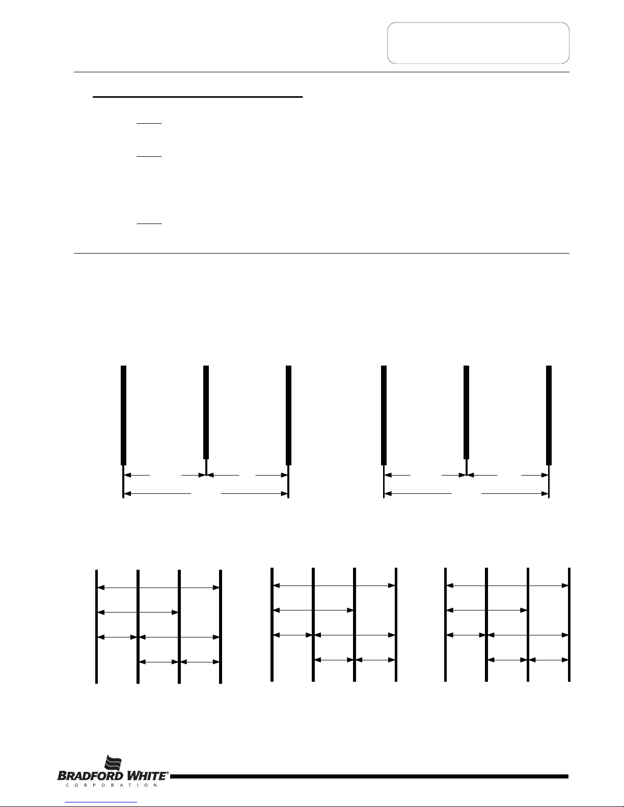
ABCNeutral
RED BLACK RED
120
120 208
208 208
208 3Ph
277
ABCNeutral
RED BLACK RED
277
277 480
480 480
480 3Ph/277 1 Ph
120
ABCNeutral
RED BLACK RED
120
120 240
240 240
240 3Ph
Common Service Wire Configurations
Amps = Watts (for single phase units) Example 4500W/240V = 18.75A
Volts
Amps = Watts (for balanced 3 phase units) Example 4500W/240V x 1.732 = 10.82A
Volts x 1.732
Watts = Amps x Volts Example 18.75A x 240V = 4500W
Ohms = Volts Example (240V) / 4500W = 12.8 Ohms
Watts
2
2
Commonly Used Formulas
Page 3
3
Page 4

GENERAL INFORMATION
Wattage Limitations at Various Voltages
Residential Electric Upright M1 & M2 Series (Non-Simultaneous operation)
M
aximum
Wattage
E
lement
Upper/Lower
Voltage
3
,000
0
21000,3/000,3
6,000
6
,000/6,00 0 208, 240
6
,000
2
77, 480
Residential Electric Upright M1 & M2 Series (Simultaneous Operation)
Maximum
Wattage
Element
Upper/Lower
Voltage
3,000
021005,1/005,1
10,000
802000,5/000,5
11,000
042005,5/005,5
12,000
6,000/6,000
277, 480
6,000/6,00 0
Residential High Efficiency Upright M2HE Series (Simultaneous Operation)
Light Duty Commercial Electric LD Series (Simultaneous Operation)
Residential Electric Lowboy M1 & M2 Series (Non-Simultaneous Operation)
Maximum
Wattage
Single
Element
Voltage
3,000
021000,3
6,000
042,802000,6
6,000
772000,6
6,000
084000,6
Residential Electric Utility Series (Single Element Operation)
Light Duty Utility Series (Single Element Operation)
Dairy Barn Deluxe DB Series (Non-Simultaneous Operation)
Dairy Barn Deluxe DB Series (Simultaneous Operation)
R
esidential High Efficiency Upright M2HE Series (Non-Simultaneous operation)
Residential Electric Lowboy M1 & M2 Series (Simultaneous Operation)
Page 4
Light Duty Commercial Electric LD Series (Non-Simultaneous Operation)
4
Page 5
GENERAL INFORMATION
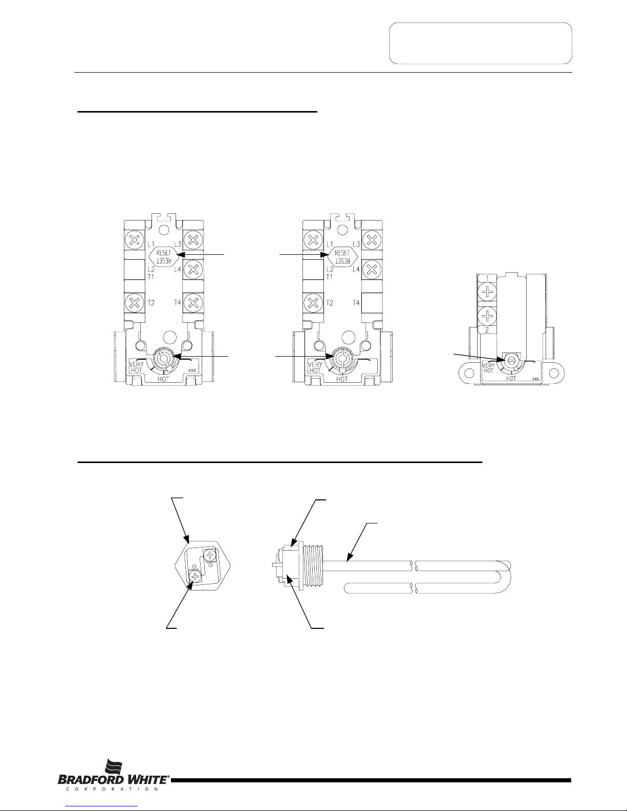
Surface M ount
Combination Thermostat/
ECO (high limit)
89T Series
Manual
E
CO (high limit)
R
eset button
Temperature
control Dial
Temperature
control Dial
Surface Mount
Thermostat
59T Series
Surface Mount
Combination Thermostat/
ECO (high limit)
89T Series
Surface Mounted Thermostats
Surface mounted thermostats are mounted into a bracket which holds the thermostat against the side of the tank.
S
urface mounted thermostats respond to tank surface temperatures to sense a call for heat, set point temperature
settings and high limit (ECO) activation. It is import that the entire back surface of the thermostat is in full contact or flush
with the tank. Improperly mounted thermostat will lead to improper heater operation.
1-½ Hex
Screw-in Flange
Terminal Block
Screw
Terminal Block
Zinc Plated Copper or
Incoloy Sheath
Element Rating Ink Stamped
on side of Terminal Block.
Direct Immersion “Screw-in” Type Heating Element
Page 5
5
Page 6
SEQUENCE OF OPERATION
R
esidential and light duty commercial electric water heaters are designed to operate using several different operating
m
odes. The common modes and sequence of operation are as follows:
1
. Single Element Operation.
2
. Double Element Non-Simultaneous Operation (single phase).
3
. Double Element Non-Simultaneous Operation (3 phase).
4. Double Element Simultaneous Operation (single phase).
5. Double Element Simultaneous Operation (3 phase).
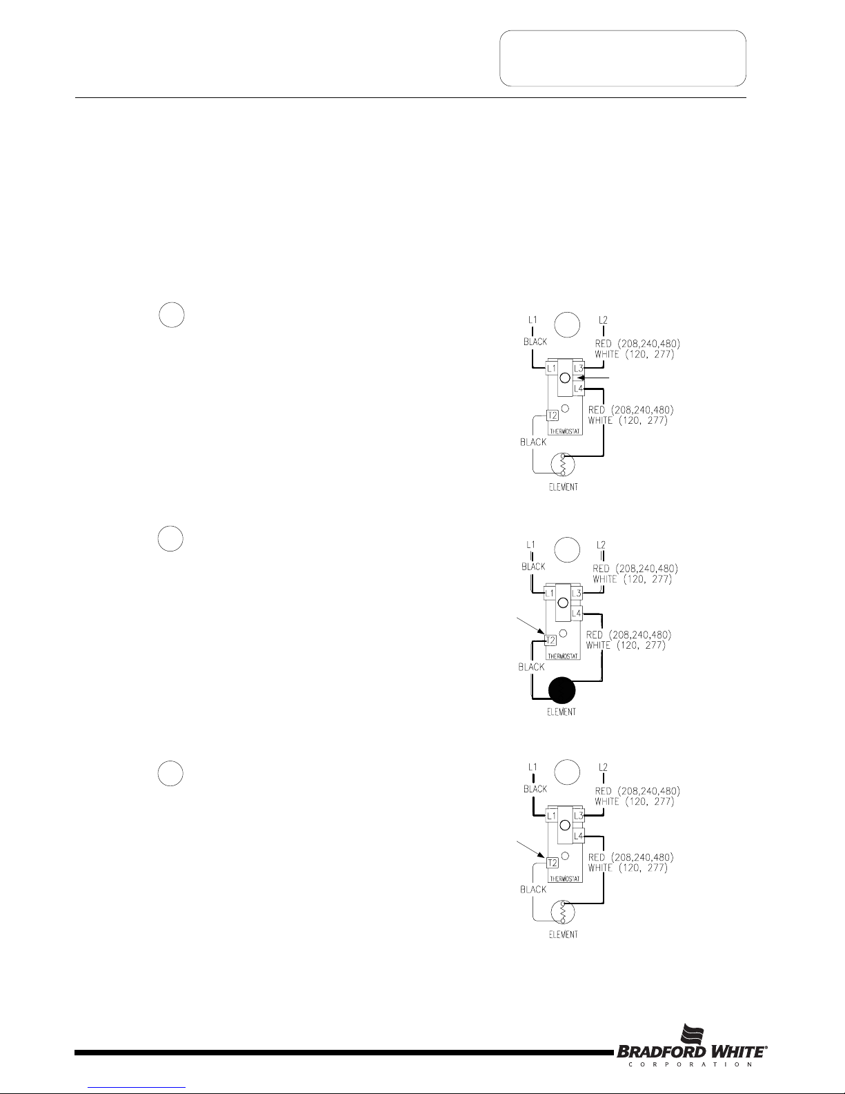
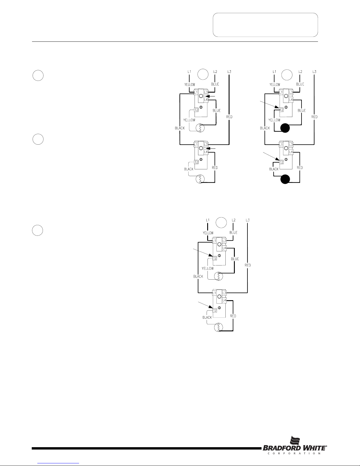
Sequence of Operation- Single Element Operation.
Line voltage is applied across terminals
L1 &L3 of the thermostat. ECO is
closed, so there is voltage at terminal L4
and to one side of the element.
1
2
When the thermostat is satisfied, it opens at
terminal T2 interrupting current flow through the
element. System is now in stand-by mode, waiting
for the next call for heat.
3
1
ECO
Closed
2
Thermostat closed
at terminal T2
3
Thermostat opens
at terminal T2
Tank is cold therefore thermostat
is closed at terminal T2 (calling for heat).
This completes the circuit and allows
current to flow through the element.
Page 6
6
Page 7
Non-Simultaneous and Simultaneous Operation
Double element electric water heaters are designed to operate in a Non-Simultaneous or Simultaneous mode.
Non-Simultaneous Mode: Allows only one heating element to operate at a time. For example, when the tank is cold,
the upper element is energized first, heating the top of the tank. Only when the upper thermostat is satisfied, the upper
e
lement is de-energized and power is directed to the lower thermostat, energizing the lower element and heating the
bottom portion of the tank until the lower thermostat is satisfied. As hot water is drawn off the tank, it is replaced with
cold water delivered through the dip tube to the bottom of the tank. The bottom of the tank cools, the lower thermostat
will call for heat energizing the lower element. If enough hot water is drawn from the tank, the top portion of the tank
cools and the upper thermostat will call for heat, de-energizing the lower element and allowing only the top element to
e
nergize until the upper thermostat is satisfied.
S
imultaneous mode: allows both heating elements to operate at the same time. That is, if either thermostat (upper or
lower) is calling for heat, the corresponding heating element is energized independent of the other.
SEQUENCE OF OPERATION
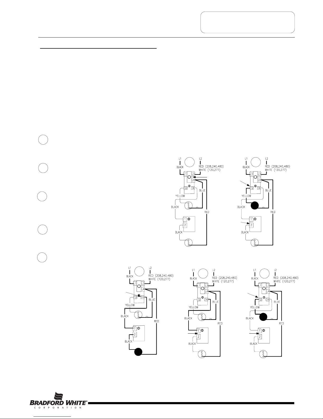
Sequence of Operation- Double Element, Non-Simultaneous Operation, Single Phase.
Line voltage is applied across terminals
L1 & L3 of the upper thermostat. ECO is
closed, so there is voltage at terminal L4
and to one side of the upper and lower
elements.
Tank is cold therefore both thermostats
are closed at terminal T2 & 2 (calling for heat). The
circuit is complete through the upper thermostat
only, allowing current to flow through upper
element.
1
2
1 2
ECO
Closed
Thermostat closed
at terminal T2
When upper thermostat is satisfied, it opens at
terminal T2 interrupting current flow through upper
element, and closes at terminal T4 allowing voltage
to pass to terminal 1 of lower thermostat. This
completes the circuit through the lower thermostat
and allows current flow through lower element.
3
3
Thermostat closed
at terminal T4
4
Thermostat open
between terminals
1 and 2
Upper
T’stat
Upper
Element
Upper
T’stat
Upper
Element
Lower
T’sta t
Lower
Element
Lower
T’sta t
Lower
Element
When the lower thermostat is satisfied, it opens at
terminal 2 interrupting current flow through lower
element. The system is now in stand-by mode
waiting for the next call for heat
4
The lower thermostat/element
combination will generally
cycle on and off more often
then the upper. In some cases,
such as a cold tank or in high
demand periods, the upper
thermostat will call for heat
(opening at terminal
T4 and closing at
terminal T2) prior to the lower
thermostat being satisfied. This
will interrupt current flow
through the lower thermostat
and element and allow current
to flow through the upper
element only. When the upper
thermostat is satisfied, it
resumes operation as
described in sequence #3
above.
5
5
Thermostat closed
between terminals
1 and 2
Upper
T’stat
Upper
Element
Lower
T’stat
Lower
Element
Upper
T’sta t
Upper
Element
Lower
T’stat
Lower
Element
Upper
T’stat
Upper
Element
Lower
T’stat
Lower
Element
Thermostat closed
a
t terminal 2
Thermostat closed
at terminal T2
Page 7
7
Page 8
SEQUENCE OF OPERATION
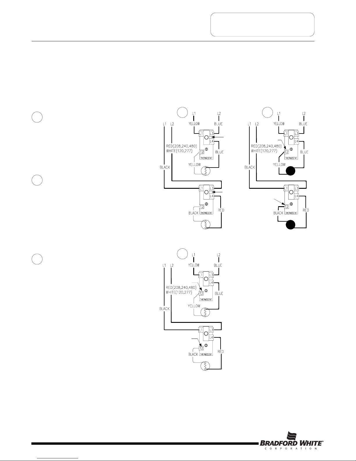
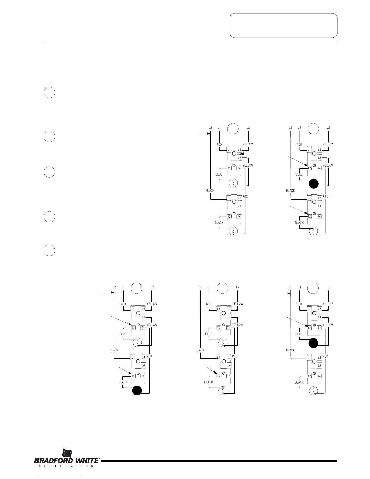
Sequence of Operation- Double Element, Simultaneous Operation, Single Phase, 4 wire service installation.
A
4 wire, double element heater wired for simultaneous operation is essentially two single element systems operating
i
ndependently. The heaters are wired internally with two independent circuits, one circuit for each thermostat/element
combination. When installed using a two wire service, the blue and red (or white) wires will be connected together,
likewise black and yellow wires will be connected together.
Line voltage from circuit one is applied
across terminals L1 & L3 of the lower
thermostat. Likewise, line voltage from
circuit two is applied across terminals L1 &
L3 of the upper thermostat. ECO in both
upper and lower thermostat is closed, so
there is voltage at terminal L4 of each
thermostat and to one side of the upper and
lower elements.
Tank is cold therefore both thermostats
are closed at terminal T2 (calling for heat).
This completes the circuit through the
thermostats and allows current to flow
through the elements.
1
2
Circuit one
Circuit two
1
ECO
Closed
ECO
Closed
Circuit one
Circuit two
2
Thermostat closed
a
t terminal T2
Thermostat closed
at terminal T2
When either thermostat is satisfied, it will
open at terminal T2, interrupting current
flow through the corresponding element. As
both thermostats satisfy, the system will be
in stand-by mode waiting for the next call
for heat. Thermostats will operate
independent of the other.
3
Circuit one
Circuit two
3
Thermostat open
at terminal T2
Thermostat open
at terminal T2
Page 8
8
Page 9
SEQUENCE OF OPERATION
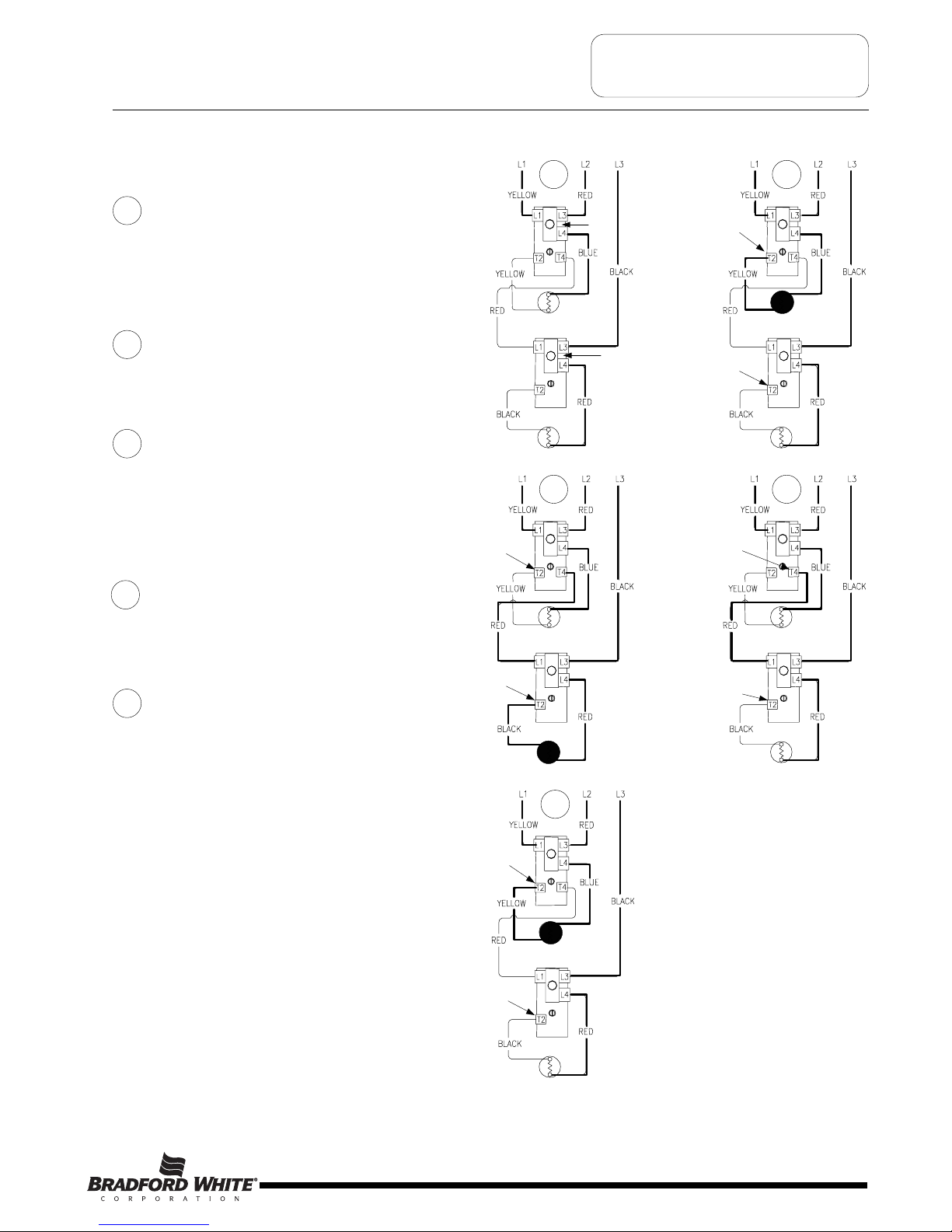
Sequence of Operation- Double Element, Non-Simultaneous Operation, 3 Phase.
Line voltage is applied across terminals L1
& L3 of upper thermostat. Likewise, Line
voltage is applied to terminal L3 of lower
thermostat. ECO in both upper & lower
t
hermostat is closed, so there is voltage at
terminal L4 of both thermostats and to one
side of both upper & lower elements.
Tank is cold therefore both thermostats
are closed at terminal T2 (calling for heat).
The circuit is complete through the upper
thermostat only allowing current to flow
through the upper element.
1
2
When the upper thermostat is satisfied, it
opens at terminal T2 interrupting current
flow through upper element, and closes at
terminal T4 allowing voltage to pass to
terminal L1 of lower thermostat. This
completes the circuit through the lower
thermostat allowing current flow through
lower element.
When the lower thermostat is satisfied, it
opens at terminal T2 interrupting the
current flow through the lower element. The
system is now in stand-by mode waiting for
the next call for heat.
3
4
The lower thermostat/element combination
will generally cycle on and off more often
then the upper. In some cases, such as a
cold tank or in high demand periods, the
upper thermostat will call for heat (opening
at terminal T4 and closing at terminal T2)
prior to the lower thermostat being satisfied.
This will interrupt current flow through the
lower thermostat and element and allow
current to flow through the upper element
only. When the upper thermostat is
satisfied, it resumes operation as described
in sequence #3 above.
5
ECO
Closed
1 2
Thermostat closed
at terminal T2
Thermostat closed
at terminal T2
3
Thermostat closed
at terminal T4
Thermostat closed
at terminal T2
4
Thermostat closed
at terminal T4
Thermostat open
at terminal T2
5
Thermostat closed
at terminal T2
Thermostat closed
at terminal T2
ECO
Closed
Page 9
9
Page 10
SEQUENCE OF OPERATION
Line voltage is applied across terminals L1
& L3 of upper thermostat. Line voltage also
extends to terminal L1 of lower thermostat.
Also, line voltage is applied to terminal L3
of lower thermostat. ECO in both upper &
lower thermostat is closed, so there is
voltage at terminal L4 of both thermostats
a
nd to one side of both upper & lower
elements.
Tank is cold therefore both thermostats
are closed at terminal T2 (calling for heat).
This completes the circuit through the
thermostats and allows current to flow
through the elements.
1
2
Sequence of Operation- Double Element, Simultaneous Operation, 3 Phase.
When either thermostat is satisfied, it will
open at terminal T2, interrupting current
flow through the corresponding element. As
both thermostats satisfy, the system will be
in stand-by mode waiting for the next call
for heat. Thermostats will operate
independent of the other.
3
Thermostat closed
at terminal T2
ECO
Closed
ECO
Closed
Thermostat closed
at terminal T2
1
2
3
Thermostat open
at terminal T2
Thermostat open
at terminal T2
Page 10
10
Page 11
SEQUENCE OF OPERATION
Sequence of Operation- Double Element, Non-Simultaneous Operation, Single Phase, Off Peak.
Some electric utility companies will offer discounts for using electricity during “Off Peak” Times of the day. The system
allows the use of an “Off Peak” meter, which interrupts power to the lower element during high power demand periods.
Line voltage is applied across terminals
L1 & L3 of the upper thermostat. Line voltage from
o
ff peak meter is supplied to terminal L1 of lower
thermostat. ECO in the upper thermostat is closed,
so there is voltage at terminal L4 of upper
thermostat and to one side of the upper element.
Tank is cold therefore both thermostats
are closed at terminal T2 (calling for heat). The
circuit is complete through the upper thermostat
only, allowing current to flow through upper
element.
1
2
When upper thermostat is satisfied, it opens at
terminal T2 interrupting current flow through upper
element, and closes at terminal T4 allowing voltage
to pass to one side of the lower element. This
completes the circuit through the lower thermostat
and off peak meter allowing current flow through
lower element.
3
When the lower thermostat is satisfied, it opens at
terminal T2 interrupting current flow through lower
element. The system is now in stand-by mode
waiting for the next call for heat
4
During peak power demand periods as determined
by the local utility, the off peak meter will interrupt
power to terminal L1 of lower thermostat. Only the
top thermostat/element combination is allowed to
operate during this period.
5
ECO
Closed
From
Off Peak
Meter
1
2
Thermostat closed
at terminal T2
3
Thermostat closed
at terminal T4
From
Off Peak
Meter
4
5
Thermostat closed
at terminal T2
Thermostat closed
at terminal T2
Thermostat open
at terminal T2
O
ff Peak
Power interrupted
T
hermostat closed
at terminal T2
Page 11
11
Page 12
TROUBLESHOOTING
Most common cause for improper electric water heater operation can be linked to heating element
failure.
When troubleshooting an electric water heater with the incidence of “No Hot Water” or “Insufficient Amount of Hot
Water” Its always a good idea to check the heating elements first following the procedure on page 15.
Common Heating Element Failures Are:
1. Dry Firing. Element may be partially submerged in water or most likely, completely exposed with no water in
tank. In some cases sediment or lime build up around an element can eventually cause an air pocket, and
within seconds, result in a dry fired element. At this point the element becomes inoperative. When element
replacement is required, be sure tank is full of water prior to energizing the water heater.
2. Grounded Element. An element with a short circuit to ground will in most cases cause the circuit breaker in
the service panel to open or shut off. In some cases there may not be enough current draw for the circuit
breaker to open. This will allow the heating element to be in continuous operation resulting in over heated
water, limited only by the ECO or Energy Cut Off located in the thermostat. Repeated actuation of the ECO
reset button on the thermostat usually is the result of a grounded element.
3. Sediment build up. Slow hot water recovery can usually be traced back to sediment or lime build up around
heating element. Sediment build up can also over time cause a dry fired element.
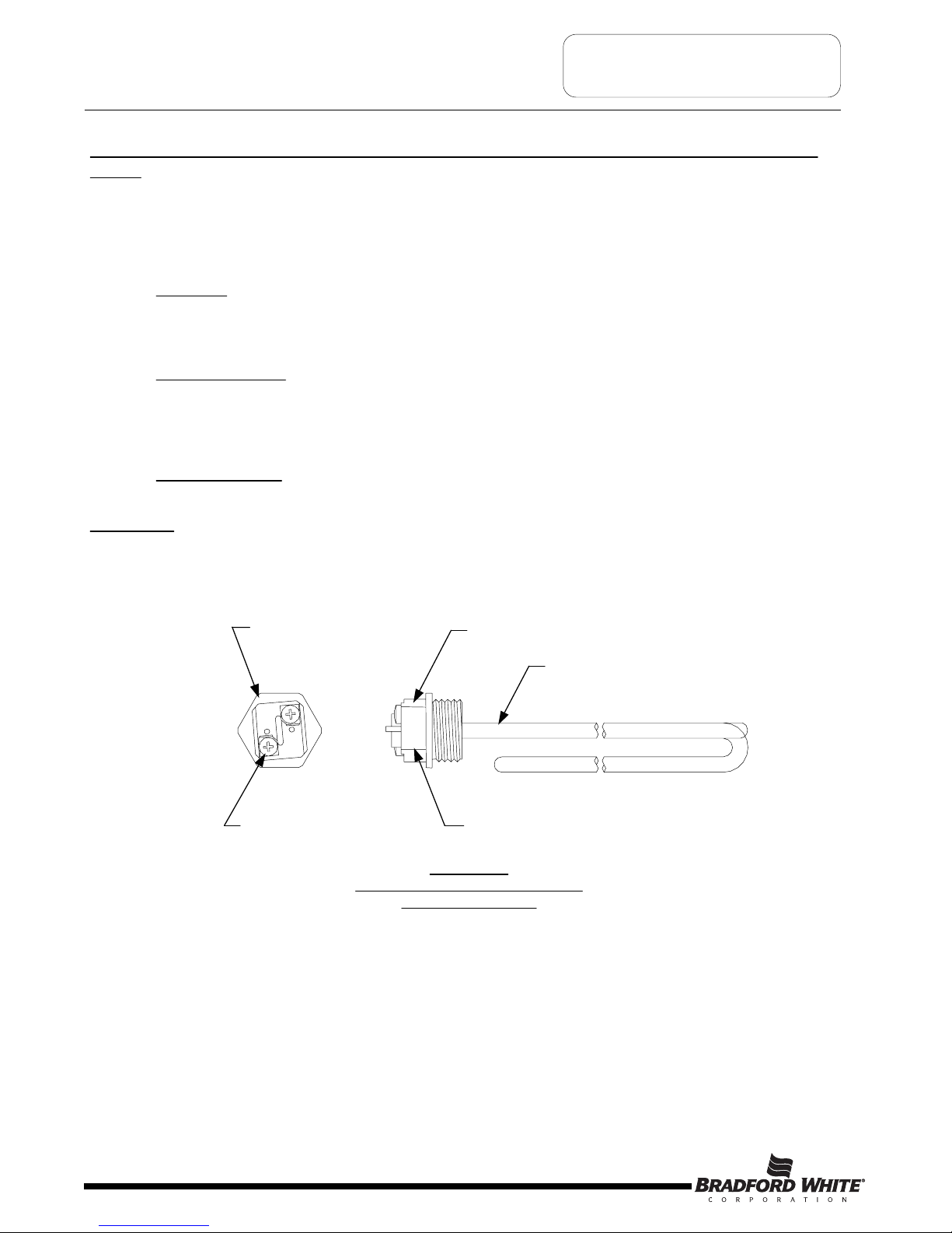
Illustration 1, below shows a common “Screw-In” type heating element identifying certain features commonly referred
to throughout this manual.
1-½ Hex
Screw-in Flange
Terminal Block
Screw
Terminal Block
Zinc Plated Copper or
Incoloy Sheath
Element Rating Ink Stamped
on side of Terminal Block.
Illustration 1
Typical Direct Immersion “Screw-In”
Type Heating Element
Page 12
0642
4500W 240V
RC02404524
12
Page 13

SYMPTOM PROBABLE CAUSE CORRECTIVE ACTION
No Hot Water
1
. No Power to heater.
2
. Loose wire connections.
3
. Inoperative upper he ating element.
4
. Inoperative upper thermostat.
5. Open ECO.
1. Inoperative lowe r heating e lement.
2. Thermostat(s) set to low.
3. Inoperative thermostat(s).
4. Loose wire connection.
5. Sediment or lime build up on element(s).
6. High demand period.
7. Undersized heater.
8. Very cold inlet water to heater.
9. Plumbing connections reversed.
10. Damaged dip tube.
Not Enough Hot
Water
Slow Hot Water
Recovery
1. Sediment or lime build up on element(s).
2. Loose wire connections.
3. Inoperative thermostat(s).
4. Derated heating element installed.
Over Heated
Water or
Continues
Operation
1. Thermostat not in contact with tank.
2. Grounded heating element(s).
3. Thermostat set to hig h.
4. Inoperative thermostat(s).
5. Inoperative ECO.
6. Undersized water heater.
1
. Check fuses or circu it breakers in service
panel.
2. Check all wire connectio ns.
3. Check heating element(s). Replace as
needed.
4
. Check thermostat(s) operation. Replace as
needed.
5. Check EC O. Reset or replace
thermostat(s) as needed.
1. Check heating element(s), replace as
needed.
2. Increase thermostat setting.
3. Check thermosta t(s), rep lace as nee ded.
4. Check all wire connection.
5. Remove heating element(s) and check for
lime build up.
6. Reduce demand.
7. Replace with large r heater.
8. Temper water to hea ter.
9. Correct plumbing connections.
10. Check dip tube, replace as needed.
1. Remove heating element(s) and check for
lime build up.
2. Check all wire connectio ns.
3. Check thermosta t(s), rep lace as nee ded.
4. Check terminal block of element for proper
voltage and wattage rating.
1. Position thermostat flush with tank surface.
2. Check heating element(s). Replace as
needed.
3. Adjust thermostat(s) to de sired setting.
4. Check thermosta t(s), rep lace as nee ded.
5. Check ECO, replace thermostat as
needed.
6. Replace with large r heater.
SERVICE
PROCEDURE
3. See Service Proced ure
RE-II, Page 15.
4
. See Service Proced ure
RE-III, Page 16.
5. See Service Proced ure
RE-I, Page 14.
1. See Service Proced ure
RE-II, Page 15.
3. See Service Proced ure
RE-III, Page 16.
5. See Service Proced ure
RE-VI, Page 34.
10. See Service Proce dure
RE-VII, Page 35.
1. See Service Proced ure
RE-VI, Page 34.
3. See Service Proced ure
RE-III, Pag e 16.
1. See Service Proced ure
RE-V, Page 33.
2. See Service Proced ure
RE-II, Page 15.
4. See Service Proced ure
RE-III, Pag e 16.
5. See Service Proced ure
RE-I, Page 14.
Page 13
Noisy (singing or
hissing) Elements
1. Lime formation on elements. 1. Remove a nd clean he ating elements.
Replace as needed.
1. See Service Proced ure
RE-VI , Page 34.
TROUBLESHOOTING
Quick Step Plan to Hot Water
1. TURN OFF power to water heater and check all wire
connections to insure they are tight and corrosion free.
2. Turn power “ON” and determine that service voltage is
present, and the high limit (ECO) has not actuated
(see procedure on page 14).
3
. Check for inoperative heating element (see procedure on page 15).
4. Check for proper thermostat operation (see procedures beginning on page 16). NOTE: Thermostat testing procedures
assume items 2 and 3 above are in working order.
WARNING
High voltage exposure. Use caution when
making voltage checks to avoid personal
injury.
13
Page 14

SERVICE PROCEDURE RE-I
Line Voltage & High Limit (ECO)
Testing
WARNING
High voltage exposure. Use caution when
making voltage checks to avoid personal injury.
Line Voltage Testing
Illustration 2 Illustration 3
1. Turn “OFF” power to water heater.
2. Remove access cover(s) from front of water
heater. Remove insulation and plastic cover
from thermostat.
3. Set multi-meter to volts AC.
4. Turn power “ON” to water heater.
5. Check voltage across terminals L1 & L3
of upper thermostat (see illustration 2).
A) Rated voltage IS present, power to the water
heater is okay.
B) Rated voltage NOT present, Check circuit breaker
at service panel.
ECO reset
button
1. Check voltage across terminals L1 & L4 upper thermostat (see illustration 3).
A) Rated Voltage IS present, ECO is okay.
B) Rated voltage NOT present, proceed to step 2.
2. Turn power “OFF” to water heater and firmly press ECO reset button on thermostat(s). Turn power “ON” and recheck
voltage across terminals L1 & L4 of upper thermostat
(see illustration 3).
A) Rated voltage IS present, the ECO has opened indicating the water in the tank is or has over heater.
Check the following:
1. Thermostat must be in full contact with tank.
2. Be sure heating element(s) is not shorted to ground (see page 15).
3. Proper thermostat operation (see procedures beginning on page 16).
B) Rated voltage NOT present, water in tank may be over heated.
1. If water is hot, turn “OFF” power to water heater and flow water through tank to cool below set point
of upper thermostat. Recheck voltage per step 1.
2. If water is cool, Replace upper thermostat.
Page 14
High Limit (ECO) Testing
14
Page 15

SERVICE PROCEDURE RE-II
Heating Element Testing
Step 1. TURN OFF POWER TO WATER HEATER.
Step 2. Remove access cover(s) from front of water
heater. Remove insulation and plastic cover
f
rom thermostat.
Step 3. Disconnect wires from heating element.
Step 4. Set multi-meter to “ohms” setting.
Step 5. Touch probes of multi-meter to screw
terminals of heating element
(see illustration 4).
Step 6. Reading should be 12.8 ohms (±6%) for a 240
volt, 4500 watt element:
A reading outside the range using the formula
above (±6%), indicates a bad element and the
element must be replaced.
Testing For Open Or Burned Out Element.
WARNING
High voltage exposure. Be sure power is turned
OFF to water heater prior to performing this
procedure.
Testing For Heating Element Short Circuit To
Ground.
Step 1. TURN OFF POWER TO WATER HEATER.
Step 2. Remove access cover(s) from front of water
heater. Remove insulation and plastic cover
from thermostat.
Step 3. Disconnect wires from heating element.
Step 4. Set multi-meter to “ohms” setting.
Step 5. Touch one probe of multi-meter to either screw
terminal of heating element and the other on
the element flange (see illustration 5). There
should be no reading on the ohm meter. Any
reading indicates a grounded element and the
element must be replaced. Repeat this step for
the other screw terminal.
Ohms = Volts
2
Watts
Element Screw Terminals
Meter Probe
Element Screw Terminal
Element Flange
M
eter Probe
Illustration 4
Illustration 5
Page 15
15
Page 16

SERVICE PROCEDURE RE-III
Residential Thermostat Testing
WARNING
High voltage exposure. Use caution to avoid
personal injury during this procedure.
Illustration 6
Single Element Operation or
Double Element, 4 Wire, Simultaneous, Single Phase
Operation.
Water In Tank Is Cold With Power ON.
1
. This procedure assumes line voltage, ECO and
elements are in working order.
2. Turn power “ON” to water heater.
3. Set multi-meter to “Volts AC”.
4. Check across terminals L4 and T2 of
thermostat (see illustration 6).
A) Rated voltage NOT present,
Recheck ECO. If ECO is okay,
replace thermostat.
B) Rated voltage IS present,
proceed to next step.
5. Check across element terminals
(see illustration 7).
A) Rated voltage NOT present,
check wire connections from
thermostat to element.
B) Rated voltage IS present,
Repeat element testing
see page 15.
Illustration 7
Water Temperature In Tank Is Above Thermostat Setting.
1. This procedure assumes line voltage, ECO and
elements are in working order.
2. Turn power “ON” to water heater.
3. Set multi-meter to “Volts AC”.
4. See illustration 6 above, check across terminals L4 and T2
of thermostat.
A) Rated voltage IS present,
replace thermostat.
B) Rated voltage NOT present,
thermostat is okay.
C) Lower than rated voltage IS present,
recheck for grounded element
(see page 15).
Reference 4 Wire, Simultaneous, Single Phase
Wiring diagram.
NOTE: Wiring consists of two single element configu rations
operating independently.
Page 16
16
Page 17

WARNING
High voltage exposure. Use caution to avoid
personal injury during this procedure.
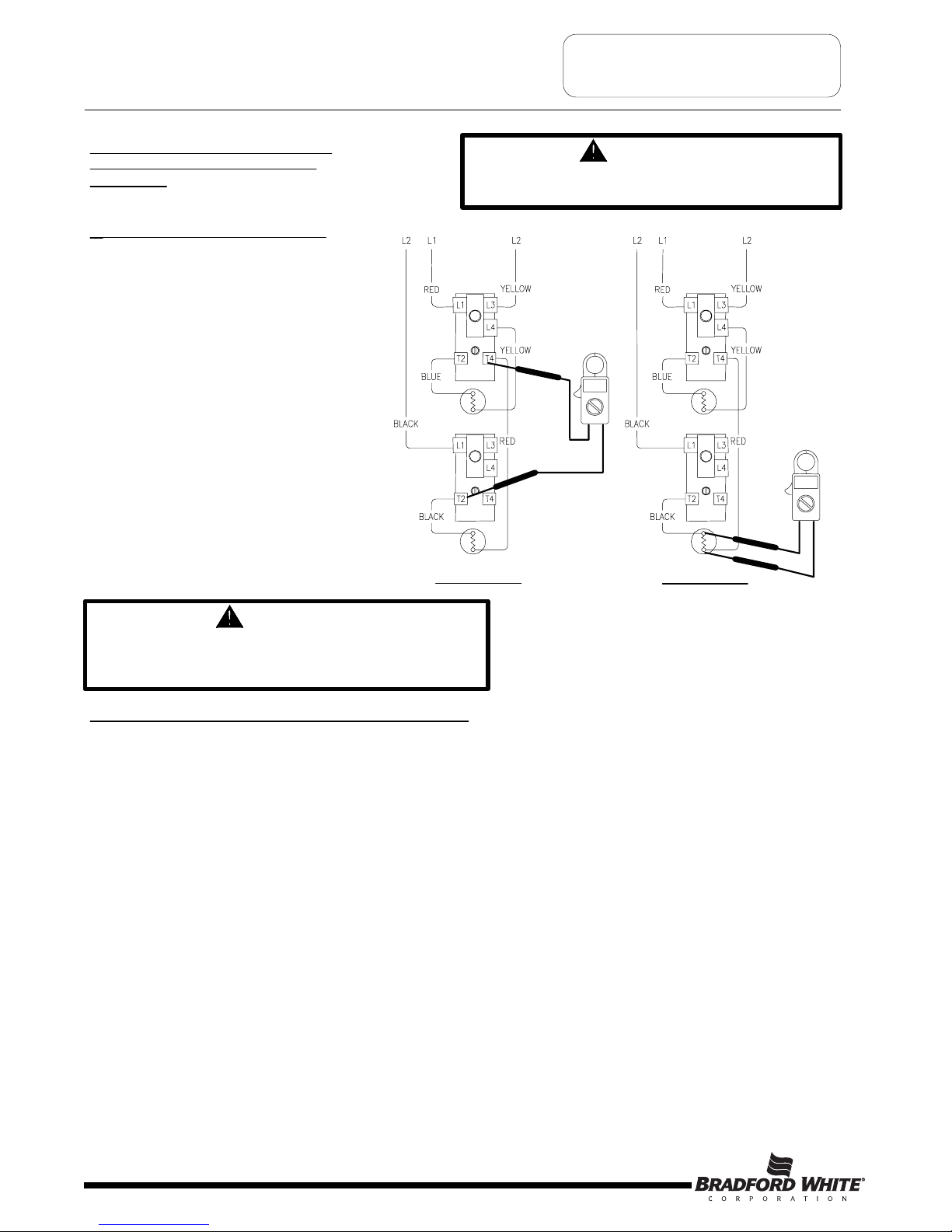
Double Element, Non-Simultaneous, Single Phase
Operation.
Water In Tank Is Cold With Power ON.
1. This procedure assumes line voltage, ECO and
elements are in working order.
2. Turn power “ON” to water heater.
3. Set multi-meter to “Volts AC”.
4. Check across terminals L4 and T2 of
upper thermostat (see illustration 8).
A) Rated voltage NOT present,
Recheck ECO. If ECO is okay,
replace thermostat.
B) Rated voltage IS present,
proceed to next step.
5. Check across element terminals
(see illustration 9).
A) Rated voltage NOT present,
check wire connections from
thermostat to element.
B) Rated voltage IS present,
Repeat element testing
see page 15.
Illustration 8
Tank Does Not Deliver Enough Hot Water.
1. This procedure assumes line voltage, ECO and
elements are in working order.
2. Turn power “ON” to water heater and set multi-meter to “Volts AC”.
3. Adjust temperature setting of upper thermostat to the highest setting.
Water temperature in tank must be below thermostat setting for this test.
4. See illustration 8 above, check voltage across terminals L4 and T2 of upper
thermostat.
A) Rated voltage IS present, okay, upper thermostat is
calling for heat. Go to step 5 below.
B) Rated voltage NOT present, replace upper thermostat.
5. Adjust temperature setting of upper thermostat to the minimum setting.
Water temperature in tank must be above thermostat setting for this test.
6. Check voltage across terminals L4 and T4 of upper thermostat
(see illustration 10).
A) Rated voltage NOT present, replace upper thermostat.
B) Rated voltage IS present, thermostat is okay. Go to step 7 on next page.
Illustration 9
Illustration 10
Page 17
SERVICE PROCEDURE RE-III
R
esidential Thermostat Testing
17
Page 18

Double Element, Non-Simultaneous, Single Phase
Operation (continued).
Not Enough Hot Water (continued).
7. Check voltage across terminal L4 of upper
thermostat and terminal 1 of lower thermostat
(see illustration 11).
A) Rated voltage NOT present,
- check wire connection between thermostats.
B) Rated voltage IS present, okay, go to step 8.
8. Adjust lower thermostat to highest setting. Water temperature in
tank must be below the lower thermostat setting for this test.
9. Check voltage across terminal L4 of upper
thermostat and terminal 2 of lower thermostat (see illustration 12).
A) Rated voltage NOT present, replace lower thermostat.
B) Rated voltage IS present, thermostat is ok.
WARNING
High voltage exposure. Use caution to avoid
personal injury during this procedure.
Illustration 11
Illustration 12
WARNING
Be sure thermostats are reset to their original
temperature settings as found prior to
thermostat testing
Page 18
SERVICE PROCEDURE RE-III
R
esidential Thermostat Testing
Water Temperature In Tank Is Above Thermostat Setting.
1. This procedure assumes Line voltage, ECO and elements are in working
order.
2. Adjust upper and lower thermostats to the lowest setting.
3. Turn power “ON” to water heater and set multi-meter to “Volts AC”.
4. Check across terminals L4 and T2 of upper thermostat
(see illustration 8 on page 17).
A) Rated voltage IS present, replace upper thermostat.
B) Rated voltage NOT present, upper thermostat is okay. Go to step
5 below.
C) Lower than rated voltage IS present, recheck for grounded upper
element (see page 15).
5. Check across terminals L4 and 2 of lower thermostat (see illustration 12).
A) Rated voltage IS present, replace lower thermostat.
B) Rated voltage NOT present, lower thermostat is okay.
C) Lower than rated voltage IS present, recheck for grounded lower
element (see page 15).
18
Page 19

WARNING
High voltage exposure. Use caution to avoid
personal injury during this procedure.
Double Element, Non-Simultaneous, Three Phase
Operation.
Water In Tank Is Cold With Power ON.
1
. This procedure assumes line voltage, ECO and
elements are in working order.
2. Turn power “ON” to water heater.
3. Set multi-meter to “Volts AC”.
4
. Check across terminals L4 and T2 of
upper thermostat (see illustration 13).
A) Rated voltage NOT present,
Recheck ECO. If ECO is okay,
replace thermostat.
B) Rated voltage IS present,
proceed to next step.
5. Check across element terminals
(see illustration 14).
A) Rated voltage NOT present,
check wire connections from
thermostat to element.
B) Rated voltage IS present,
Repeat element testing,
see page 15.
Illustration 13 Illustration 14
Tank Does Not Deliver Enough Hot Water.
1. This procedure assumes line voltage, ECO and
elements are in working order.
2. Turn power “ON” to water heater and set multi-meter to “Volts AC”
3. Adjust temperature setting of upper thermostat to the highest setting.
Water temperature in tank must be below thermostat setting for this test.
4. See illustration 13 above, check voltage across terminals L4 & T2 of upper
thermostat.
A) Rated voltage IS present, okay, upper thermostat is
calling for heat. Go to step 5 below.
B) Rated voltage NOT present, replace upper thermostat.
5. Adjust temperature setting of upper thermostat to the minimum setting.
Water temperature in tank must be above thermostat setting for this test.
6. Check voltage across terminals T4 of upper thermostat & L3 of lower thermostat
(see illustration 15).
A) Rated voltage NOT present, replace upper thermostat.
B) Rated voltage IS present, upper thermostat is okay. Go to step 7 on next
page.
Illustration 15
Page 19
SERVICE PROCEDURE RE-III
R
esidential Thermostat Testing
19
Page 20

Double Element, Non-Simultaneous,
Three Phase Operation (continued).
Tank Does Not Deliver Enough Hot Water (continued)
7. Check voltage across terminal L1 & L3 of lower thermostat (see illustration 16).
A) Rated voltage NOT present, check wire connection between thermostats.
B) Rated voltage is present, okay, go to step 8.
8. Adjust lower thermostat to highest setting. Water temperature in tank must be below
the lower thermostat setting for this test.
9. Check voltage across terminal L4 & T2 of lower thermostat (see illustration 17).
A) Rated voltage NOT present, recheck ECO (see page 14). If ECO okay,
replace lower thermostat.
B) Rated voltage IS present, thermostat is ok. Check wire connection to lower
element. If connection okay, recheck lower element (see page 15).
Illustration 16
Illustration 17
WARNING
High voltage exposure. Use caution to avoid
personal injury during this procedure.
WARNING
Be sure thermostats are reset to their original
temperature settings as found prior to
thermostat testing
Page 20
SERVICE PROCEDURE RE-III
R
esidential Thermostat Testing
Water Temperature In Tank Is Above Thermostat Setting.
1. This procedure assumes Line voltage, ECO and elements are in working
order.
2. Adjust upper and lower thermostats to the lowest setting.
3. Turn power “ON” to water heater and set multi-meter to “Volts AC”.
4. Check across terminals L4 and T2 of upper thermostat
(see illustration 13 on page 19).
A) Rated voltage IS present, replace upper thermostat.
B) Rated voltage NOT present, upper thermostat is okay. Go to step
5 below.
C) Lower than rated voltage IS present, recheck for grounded upper
element (see page 15).
5. Check across terminals L4 and T2 of lower thermostat (see illustration 17).
A) Rated voltage IS present, replace lower thermostat.
B) Rated voltage NOT present, lower thermostat is okay.
C) Lower than rated voltage IS present, recheck for grounded lower
element (see page 15).
20
Page 21

Double Element, Simultaneous, Three Phase
Operation.
Water In Tank Is Cold Or Not Enough Hot
Water With Power ON.
1. This procedure assumes line voltage,
ECO and elements are in working order.
2
. Adjust temperature setting for both
thermostats to the highest setting.
2. Turn power “ON” to water heater.
3. Set multi-meter to “Volts AC”.
4. Check across terminals L4 and T2 of
upper thermostat (see illustration 18).
A) Rated voltage NOT present,
Recheck ECO (see page 14).
If ECO is okay, replace
thermostat.
B) Rated voltage IS present,
proceed to next step.
5. Check across upper element terminals
(see illustration 19).
A) Rated voltage NOT present,
check wire connections from
thermostat to element.
B) Rated voltage IS present,
Repeat element testing
see page 15.
6. Check across terminals L1 & L3 of
lower thermostat (see illustration 20).
A) Rated voltage NOT present,
check wire connections from
upper to lower thermostats.
B) Rated voltage IS present,
okay, go to step 7.
7. Check across terminals L4 and T2 of
lower thermostat (see illustration 21).
A) Rated voltage NOT present,
Recheck ECO (see page 14). If
ECO is okay, replace thermostat.
B) Rated voltage IS present,
proceed to next step.
8. Check across lower element terminals.
A) Rated voltage NOT present,
check wire connections from
thermostat to element.
B) Rated voltage IS present,
Repeat element testing
see page 15.
WARNING
High voltage exposure. Use caution to avoid
personal injury during this procedure.
Illustration 18
Illustration 19
Illustration 20
Illustration 21
WARNING
Be sure thermostats are reset to their original
temperature settings as found prior to
thermostat testing
Page 21
S
ERVICE PROCEDURE RE-III
Residential Thermostat Testing
21
Page 22

Double Element, Simultaneous, Three Phase
Operation (continued).
Water Temperature In Tank Is Above Thermostat
Setting.
1. This procedure assumes Line voltage, ECO and
elements are in working order.
2. Adjust upper and lower thermostat to the lowest setting.
3. Turn power “ON” to water heater.
4. Set multi-meter to “Volts AC”.
5. Check across terminals L4 and T2 of
upper thermostat (see illustration 22).
A) Rated voltage IS present,
replace upper thermostat.
B) Rated voltage NOT present,
upper thermostat is okay. Go to step 6 below.
C) Lower than rated voltage IS present,
recheck for grounded upper element
(see page 15).
6. Check across terminals L4 and T2 of
lower thermostat (see illustration 23).
A) Rated voltage IS present,
replace lower thermostat.
B) Rated voltage NOT present,
lower thermostat is okay.
C) Lower than rated voltage IS present,
recheck for grounded lower element
(see page 15).
Illustration 22
WARNING
High voltage exposure. Use caution to avoid
personal injury during this procedure.
Illustration 23
Page 22
SERVICE PROCEDURE RE-III
R
esidential Thermostat Testing
22
Page 23

Double Element, Non-Simultaneous, Single Phase,
Off Peak Operation.
W
ater In Tank Is Cold With Power ON.
1. This procedure assumes line voltage,
ECO and elements are in working order.
2
. Turn power “ON” to water heater.
3. Set multi-meter to “Volts AC”.
4
. Check across terminals L4 and T2 of
upper thermostat (see illustration 24).
A) Rated voltage NOT present,
Recheck ECO (see page 14).
If ECO is okay, replace thermostat.
B) Rated voltage IS present,
proceed to next step.
5. Check across element terminals
(see illustration 25).
A) Rated voltage NOT present,
check wire connections from
thermostat to element.
B) Rated voltage IS present,
Repeat element testing
see page 15.
Illustration 24
Illustration 25
Tank Does Not Deliver Enough Hot Water.
1. This procedure assumes line voltage, ECO and elements are in
working order. Be sure OFF PEAK meter has not interrupted
line voltage.
2. Turn power “ON” to water heater and set multi-meter to “Volts AC”.
3. Adjust temperature setting of upper & lower thermostat to the
Highest setting. Water temperature in tank must be below thermostat
setting for this test.
4. See illustration 24 above. Check voltage across terminals L4 & T2 of
upper thermostat.
A) Rated voltage IS present, okay, upper thermostat is calling
for heat. Go to step 5 below.
B) Rated voltage NOT present, replace upper thermostat.
5. Adjust temperature setting of upper thermostat to the minimum
setting. Water temperature in tank must be above thermostat setting
for this test.
6. Check voltage across terminals T4 of upper thermostat & L1 of lower
thermostat (see illustration 26).
A) Rated voltage NOT present, replace upper thermostat.
B) Rated voltage IS present, upper thermostat is okay. Go to
step 7 on next page.
Illustratio n 26
WARNING
High voltage exposure. Use caution to avoid
personal injury during this procedure.
Page 23
SERVICE PROCEDURE RE-III
Residential Thermostat Testing
23
Page 24
WARNING
High voltage exposure. Use caution to avoid
personal injury during this procedure.
Double Element, Non-Simultaneous,
Single Phase, Off Peak Operation.
(continued)
Not Enough Hot Water (continued).
7. Check voltage across terminal T4 of upper
thermostat & T2 of lower Thermostat.
(see illustration 27).
A) Rated voltage NOT present,
Replace lower thermostat.
B) Rated voltage is present, okay,
go to step 8.
8. Check voltage across lower element
(see illustration 28).
A) Rated voltage NOT present,
Check wire connections between
thermostats & element.
B) Rated voltage IS present,
Repeat element testing
see page 15.
Illustratio n 27
Illustration 28
Page 24
SERVICE PROCEDURE RE-III
R
esidential Thermostat Testing
Water Temperature In Tank Is Above Thermostat Setting.
1. This procedure assumes Line voltage, ECO and elements are in working order.
2. Adjust upper and lower thermostats to the lowest setting.
3. Turn power “ON” to water heater and set multi-meter to “Volts AC”.
4. Check across terminals L4 and T2 of upper thermostat (see illustration 24 on page 23).
A) Rated voltage IS present, replace upper thermostat.
B) Rated voltage NOT present, upper thermostat is okay. Go to step 5 below.
C) Lower than rated voltage IS present, recheck for grounded upper element (see page 15).
5. Check across terminals T4 of upper thermostat and T2 of lower thermostat (see illustration 27 above).
A) Rated voltage IS present, replace lower thermostat.
B) Rated voltage NOT present, lower thermostat is okay.
C) Lower than rated voltage IS present, recheck for grounded lower element (see page 15).
WARNING
Be sure thermostats are reset to their original
temperature settings as found prior to
thermostat testing
24
Page 25

SERVICE PROCEDURE RE-IV
Light Duty Commercial
Thermostat Testing
WARNING
High voltage exposure. Use caution to avoid
personal injury during this procedure.
D
ouble Element, Non-Simultaneous, Single Phase
O
peration.
W
ater In Tank Is Cold With Power ON.
1. This procedure assumes line voltage, ECO and
elements are in working order.
2. Turn power “ON” to water heater.
3. Set multi-meter to “Volts AC”.
4. Check across terminals L4 and T2 of
upper thermostat (see illustration 29).
A) Rated voltage NOT present,
Recheck ECO (see page 14). If
ECO is okay, replace thermostat.
B) Rated voltage IS present,
proceed to next step.
5. Check across element terminals
(see illustration 30).
A) Rated voltage NOT present,
check wire connections from
thermostat to element.
B) Rated voltage IS present,
Repeat element testing
see page 15.
Illustration 29 Illustration 30
Tank Does Not Deliver Enough Hot Water.
1. This procedure assumes line voltage, ECO and elements are in
working order.
2. Turn power “ON” to water heater and set multi-meter to “Volts AC”
3. Adjust temperature setting of upper & lower thermostat to the
Highest setting. Water temperature in tank must be below thermostat
setting for this test.
4. See illustration 29 above. Check voltage across terminals L4 & T2 of
upper thermostat.
A) Rated voltage IS present, okay, upper thermostat is calling
for heat. Go to step 5 below.
B) Rated voltage NOT present, replace upper thermostat.
5. Adjust temperature setting of upper thermostat to the minimum
setting. Water temperature in tank must be above thermostat setting
for this test.
6. Check voltage across terminals L3 & T4 of upper
thermostat (see illustration 31).
A) Rated voltage NOT present, replace upper thermostat.
B) Rated voltage IS present, upper thermostat is okay. Go to
step 7 on next page.
Illustratio n 31
Page 25
25
Page 26

WARNING
High voltage exposure. Use caution to avoid
personal injury during this procedure.
Double Element, Non-Simultaneous,
S
ingle Phase Operation (continued)
T
ank Does Not Deliver Enough Hot
Water (continued).
7. Check voltage across terminal L3 of upper
thermostat & T2 of lower Thermostat.
(see illustration 32).
A) Rated voltage NOT present,
Replace lower thermostat.
B) Rated voltage is present, okay,
go to step 8.
8. Check voltage across lower element
(see illustration 33).
A) Rated voltage NOT present,
Check wire connections between
thermostats & element.
B) Rated voltage IS present,
Repeat element testing
see page 15.
Illu st ratio n 32 Illustration 33
WARNING
Be sure thermostats are reset to
their original temperature settings
as found prior to thermostat
testing
Illustration 34
Water Temperature In Tank Is Above Thermostat Setting.
1. This procedure assumes line voltage, ECO and elements are in working order.
2, Adjust upper and lower thermostat to the lowest setting.
3. Turn power “ON” to water heater and Set multi-meter to “Volts AC”
4. See illustration 32 above. Check across terminal L3 of upper thermostat
& T2 of lower thermostat.
A) Rated voltage IS present, replace lower thermostat.
B) Rated voltage NOT present, okay, go to step 5 below.
C) Lower than rated voltage IS present, recheck for grounded lower
element see page 15.
5. Check across terminal L4 & T2 of upper thermostat (see illustration 34).
A) Rated voltage IS present, replace upper thermostat.
B) Rated voltage NOT present, upper thermostat is okay.
C) lower than rated voltage IS present, recheck for grounded upper
element see page 15.
Page 26
SERVICE PROCEDURE RE-IV
Light Duty Commercial
Thermostat Testing
26
Page 27

WARNING
High voltage exposure. Use caution to avoid
personal injury during this procedure.
Double Element, Simultaneous, Single Phase
Operation.
Water In Tank Is Cold Or Not Enough Hot
Water With Power ON.
1. This procedure assumes line voltage,
ECO and elements are in working order.
2. Adjust temperature setting for both
thermostats to the highest setting.
3. Turn power “ON” to water heater.
4. Set multi-meter to “Volts AC”
5. Check across terminals L4 and T2 of
upper thermostat (see illustration 35).
A) Rated voltage NOT present,
Recheck upper ECO
(see page 14). If ECO
is okay, replace upper thermostat.
B) Rated voltage IS present,
proceed to next step.
6. Check across upper element terminals
(see illustration 36).
A) Rated voltage NOT present,
check wire connections from
thermostat to upper element.
B) Rated voltage IS present,
Repeat element testing
see page 15.
7. Check across terminal L3 of upper thermostat
and T2 of lower thermostat (see illustration 37).
A) Rated voltage NOT present,
Check ECO (see page 14) & wire
connections at upper & lower
thermostats. If okay,
replace lower thermostat.
B) Rated voltage IS present,
proceed to next step.
8. Check across lower element terminals
(see illustration 38).
A) Rated voltage NOT present,
check lower element wire
connections to the thermostats.
B) Rated voltage IS present,
Repeat lower element testing
see page 15
Illustration 35
Illustration 36
Illustratio n 37 Illustration 38
WARNING
Be sure thermostats are reset to
their original temperature settings
as found prior to thermostat
testing
Page 27
SERVICE PROCEDURE RE-IV
Light Duty Commercial
Thermostat Testing
27
Page 28

WARNING
High voltage exposure. Use caution to avoid
personal injury during this procedure.
Double Element, Simultaneous, Single Phase
Operation (continued)
Water Temperature In Tank Is Above Thermostat
Setting.
1. This procedure assumes line voltage, ECO and
elements are in working order.
2
. Adjust upper and lower thermostat to the lowest setting.
3. Turn power “ON” to water heater.
4. Set multi-meter to “Volts AC”
5. Check across terminals L4 and T2 of
upper thermostat (see illustration 39).
A) Rated voltage IS present,
replace upper thermostat.
B) Rated voltage NOT present,
upper thermostat is okay. Go to step 6 below.
C) lower than rated voltage IS present,
recheck for grounded upper element
see page 15.
6. Check across terminal L3 of upper thermostat and
T2 of lower thermostat (see illustration 40).
A) Rated voltage IS present,
replace lower thermostat.
B) Rated voltage NOT present,
lower thermostat is okay.
C) lower than rated voltage IS present,
recheck for grounded lower element
see page 15.
Illustration 39
Illustration 40
Page 28
SERVICE PROCEDURE RE-IV
L
ight Duty Commercial
Thermostat Testing
28
Page 29

WARNING
High voltage exposure. Use caution to avoid
personal injury during this procedure.
Double Element, Non-Simultaneous, Three Phase
Operation.
W
ater In Tank Is Cold With Power ON.
1. This procedure assumes line voltage, ECO and
elements are in working order.
2
. Turn power “ON” to water heater.
3. Set multi-meter to “Volts AC”
4
. Check across terminals L4 and T2 of
upper thermostat (see illustration 41).
A) Rated voltage NOT present,
Recheck upper ECO. If ECO is okay,
replace thermostat.
B) Rated voltage IS present,
proceed to next step.
5. Check across element terminals
(see illustration 42).
A) Rated voltage NOT present,
check wire connections from
thermostat to element.
B) Rated voltage IS present,
Repeat element testing
see page 15.
Illustration 41 Illustration 42
Tank Does Not Deliver Enough Hot Water.
1. This procedure assumes line voltage, ECO and elements are in
working order.
2. Turn power “ON” to water heater and set multi-meter to “Volts AC”
3. Adjust temperature setting of upper & lower thermostat to the
Highest setting. Water temperature in tank must be below thermostat
setting for this test.
4. See illustration 41 above. Check voltage across terminals L4 & T2 of
upper thermostat.
A) Rated voltage IS present, okay, upper thermostat is calling
for heat. Go to step 5 below.
B) Rated voltage NOT present, replace upper thermostat.
5. Adjust temperature setting of upper thermostat to the minimum
setting. Water temperature in tank must be above thermostat setting
for this test.
6. Check voltage across terminals L3 & T4 of upper
thermostat (see illustration 43).
A) Rated voltage NOT present, replace upper thermostat.
B) Rated voltage IS present, upper thermostat is okay. Go to
step 7 on next page.
Illustratio n 43
Page 29
SERVICE PROCEDURE RE-IV
Light Duty Commercial
Thermostat Testing
29
Page 30

WARNING
High voltage exposure. Use caution to avoid
personal injury during this procedure.
Double Element, Non-Simultaneous,
Three Phase Operation (continued).
Tank Does Not Deliver Enough Hot Water
(continued).
7. Check voltage across terminal L1 of upper
thermostat & T2 of lower Thermostat.
(see illustration 44).
A) Rated voltage NOT present,
Replace lower thermostat.
B) Rated voltage is present, okay,
go to step 8.
8. Check voltage across lower element
(see illustration 45).
A) Rated voltage NOT present,
Check wire connections between
thermostats & element.
B) Rated voltage IS present,
Repeat element testing
see page 15.
Illustratio n 44
Illustratio n 45
WARNING
Be sure thermostats are reset to
their original temperature settings
as found prior to thermostat
testing
Water Temperature In Tank Is Above Thermostat Setting.
1. This procedure assumes line voltage, ECO and elements are in working order.
2. Adjust upper and lower thermostat to the lowest setting.
3. Turn power “ON” to water heater and Set multi-meter to “Volts AC”.
4. See illustration 44 above. Check across terminal L1 of upper thermostat
& T2 of lower thermostat.
A) Rated voltage IS present, replace lower thermostat.
B) Rated voltage NOT present, okay, go to step 5 below.
C) lower than rated voltage IS present, recheck for grounded lower
element.
5. Check across terminal L4 & T2 of upper thermostat (see illustration 46).
A) Rated voltage IS present, replace upper thermostat.
B) Rated voltage NOT present, upper thermostat is okay.
C) lower than rated voltage IS present, recheck for grounded upper
element, see page 15.
Illustration 46
Page 30
SERVICE PROCEDURE RE-IV
Light Duty Commercial
Thermostat Testing
30
Page 31

WARNING
High voltage exposure. Use caution to avoid
personal injury during this procedure.
Illustration 47
Illustration 48
Double Element, Simultaneous, Three Phase
Operation.
Water In Tank Is Cold Or Not Enough Hot
Water With Power ON.
1. This procedure assumes line voltage,
ECO and elements are in working order.
2. Adjust temperature setting for both
thermostats to the highest setting.
3. Turn power “ON” to water heater.
4. Set multi-meter to “Volts AC”
5. Check across terminals L4 and T2 of
upper thermostat (see illustration 47).
A) Rated voltage NOT present,
Recheck upper ECO
(see page 14). If ECO
is okay, replace upper thermostat.
B) Rated voltage IS present,
proceed to next step.
6. Check across upper element terminals
(see illustration 48).
A) Rated voltage NOT present,
check wire connections from
thermostat to upper element.
B) Rated voltage IS present,
Repeat element testing
see page 15
7. Check across terminal L4 of upper thermostat
and T2 of lower thermostat (see illustration 49).
A) Rated voltage NOT present,
Check ECO (see page 14) & wire
connections at upper & lower
thermostats. If okay, replace
lower thermostat.
B) Rated voltage IS present,
proceed to next step.
8. Check across lower element terminals
(see illustration 50).
A) Rated voltage NOT present,
check lower element wire
connections to thermostat.
B) Rated voltage IS present,
Repeat lower element testing
see page 15.
Illustration 49
WARNING
Be sure thermostats are reset to
their original temperature settings
as found prior to thermostat
testing
Illustration 50
Page 31
SERVICE PROCEDURE RE-IV
Light Duty Commercial
Thermostat Testing
31
Page 32

S
ERVICE PROCEDURE RE-IV
Light Duty Commercial
Thermostat Testing
WARNING
High voltage exposure. Use caution to avoid
personal injury during this procedure.
Double Element, Simultaneous, Three Phase
Operation (continued).
Water Temperature In Tank Is Above Thermostat
Setting.
1. This procedure assumes line voltage, ECO and
elements are in working order.
2. Adjust upper and lower thermostat to the lowest setting.
3. Turn power “ON” to water heater.
4. Set multi-meter to “Volts AC”
5. Check across terminals L4 and T2 of
upper thermostat (see illustration 51).
A) Rated voltage IS present,
replace upper thermostat.
B) Rated voltage NOT present,
upper thermostat is okay. Go to step 6 below.
C) lower than rated voltage IS present,
recheck for grounded upper element
see page 15.
6. Check across terminals L4 & T2 of lower thermostat
(see illustration 52).
A) Rated voltage IS present,
replace lower thermostat.
B) Rated voltage NOT present,
lower thermostat is okay.
C) lower than rated voltage IS present,
recheck for grounded lower element.
Illustratio n 51
Illustratio n 52
Page 32
32
Page 33

SERVICE PROCEDURE RE-V
Thermostat Removal and Replacement
Front View
Thermostat Mounting
Thermostat Removal
1. Turn power “OFF” To water heater.
2
. Remove access cover and insulation.
3. Remove plastic thermostat protector from thermostat.
4. Disconnect wires from thermostat terminals. It may be necessary to label wires for proper re-connection to
new thermostat.
5
. Note thermostat temperature setting for proper setting of new thermostat.
6
. Slide thermostat upwards and out of mounting bracket.
WARNING
High voltage exposure. Be sure power is
“OFF” when performing this procedure.
Thermostat Replacement
1. Use a stiff brush to remove any debris or loose scale from tank surface where new thermostat will be installed.
2. Slide new thermostat down into thermostat bracket until it snaps into place. IMPORTANT! Thermostat must set
completely flat or flush to tank surface. An improperly installed thermostat will cause improper water heater
operation.
3. Refer to the wire diagram located on the inside of the access cover and re-connect wires to the thermostat. Be
sure wire connections are snug and corrosion free. Do not over tighten, doing so may damage thermostat.
4. Set thermostat to the original thermostat setting found on the old thermostat.
5. Re-install plastic thermostat protector.
6. Re-install insulation and access cover.
7. Restore power to water heater and verify proper heater operation.
Thermostat
Thermostat
mounting
bracket
Side View
Proper Thermostat
Mounting
Tank Surface
Side View
Improper Thermostat
Mounting
Proper Thermostat mounting
flush with tank surface
Improper Thermostat mounting.
Thermostat not flush with tank surface
Page 33
33
Page 34

SERVICE PROCEDURE RE-VI
Heating Element Removal
and Replacement
Heating Element Removal
1. Turn power “OFF” To water heater.
2
. Turn off cold water supply to heater. Connect hose to drain
spigot of water heater and route to an open drain. Open
a nearby hot water faucet to vent heater for draining. Open
drain spigot of water heater and allow heater to drain
to a point below the Element(s).
3. Close drain spigot and remove hose.
4. Remove access cover and insulation.
5. Remove plastic thermostat protector from thermostat.
6. Disconnect wires from element terminals.
7. Remove element from tank using 1-½ deep well socket or appropriate wrench. Unscrew element counter-clockwise to
remove from tank.
8. Be sure to remove old element gasket from the tank. It is not recommended to be re-used.
WARNING
High voltage exposure. Be sure power is
“OFF” when performing this procedure.
Heating Element Replacement
1. Check element terminal block for proper electrical rating. NOTE: Some elements have dual ratings, be sure to check
all surfaces of the element terminal block (see illustration below).
2. Apply new element gasket to the new element. Be sure gasket is seated flat against element flange without rolls or
gaps (see illustration below).
3. Clean any debris from element fitting on tank. Lubricate element threads as needed with thread lubricant.
4. Thread new element clockwise into tank. Tighten element using 1-½ deep well socket or appropriate wrench. Do not
over tighten, over tightening may damage element gasket.
5. Reconnect wires to element, be sure wires are snug and corrosion free. Do not over tighten, doing so may damage
terminal block.
6. Resume water supply to heater, be sure tank is full of water and check for leaks.
7. Re-install plastic thermostat protector.
8. Re-install insulation and access cover.
9. To resume operation, BE SURE TANK IS FULL OF WATER and restore power to water heater. Verify proper heater
operation.
WARNING
Heater components and stored water may be
HOT when performing the following steps in
this procedure. Take necessary precaution to
prevent personal injury.
0642
4500W 240V
RC02404524
Date Code
Element Rating.
Example: (4500 Watt, 240 Volt)
Manufacturer Identification
Element Flange
Element Gasket Seated Flat Against
Element Fla nge Witho ut Rolls o r Gaps
Page 34
Terminal
Block
34
Page 35

Page 35
Step 1. Turn power “OFF” to water heater.
Step 2. Turn off cold water supply to heater. Connect hose to drain spigot of water heater and route to an open drain.
Open a nearby hot water faucet to vent heater for draining. Open drain spigot of water heater and allow
h
eater to drain to a point below the inlet connection nipple.
Step 3. Close drain spigot and remove hose.
Step 4. Disconnect inlet nipple from plumbing system.
Step 5. With an appropriate wrench, remove inlet nipple/dip tube from the water heater. Use caution not to damage
nipple threads.
Step 6. Visually Inspect inlet nipple/dip tube. Inlet nipple/dip tube should be free of cracks and any blockage.
Hydro-jets located near the bottom of the dip tube should be open and free of any blockage.
Anti-siphon hole located approximately 6" from the bottom of nipple, should be free of any blockage.
Any damage such as cracks, restriction due to deformation or unintentional holes are not field repairable
and the inlet nipple/dip tube must be replaced.
Step 7. Upon completion of inspection or subsequent replacement, reinstall inlet nipple/dip tube into heater. Connect
nipple to plumbing system, close spigot and remove drain hose, resume water supply and refill heater with
water.
Step 8. To resume operation, BE SURE TANK IS FULL OF WATER and turn power “ON” to water heater.
Dip Tube Inspection and Replacement
WARNING
Heater components and stored water may be HOT when performing the following steps in
this procedure. Take necessary precaution to prevent personal injury.
SERVICE PROCEDURE RE-VII
Dip Tube and Anode Inspection and
Replacement
Anode Inspection and Replacement
Step 1. Turn power “OFF” to water heater.
Step 2. Turn off cold water supply to heater. Connect hose to drain spigot of water heater and route to an open drain.
Open a nearby hot water faucet to vent heater for draining. Open drain spigot of water heater and allow
heater to drain to a point below the outlet connection nipple.
Step 3. Close drain spigot and remove hose.
Step 4. Disconnect outlet nipple from plumbing system.
Step 5. With an appropriate wrench, remove outlet nipple/anode from the water heater. Use caution not to damage
nipple threads.
Step 6. Visually Inspect outlet nipple/anode. Outlet nipple/anode should show signs of depletion, this is normal.
If depletion is ½ of the original anode diameter (original diameter approximately ¾”), replacement is
recommended. If any of the steel core of the anode is exposed, replacement is recommended.
Step 7. Upon completion of inspection or subsequent replacement, reinstall outlet nipple/anode into heater. Connect
nipple to plumbing system, close spigot and remove drain hose, resume water supply and refill heater with
water.
Step 8. To resume operation, BE SURE HEATER IS FULL OF WATER and turn power “ON” to water heater.
35
Page 36

Page 36
Generic Parts List
1. T&P Relief Valve
2. Heat Trap Insert (Outlet)
3. Hot Water Outlet/Anode
4. Cover Conduit/Ground
5. Junction Box Cover
6. Heat Trap Insert (Inlet)
7. Cold Water Inlet Dip Tube
8. Thermostat Protector (Large)
9. Thermostat w/High Limit (89T33)
10. Thermostat Mounting Bracket
11. Heating Element
12. Element Gasket
13. Access Cover
14. Lower Thermostat Protector (Small)
15. Thermostat (59T)
16. Brass Drain Valve
17. Thermostat w/High Limit (89T13)
18. ASSE Approved Mixing Device
19. Kit Heat Trap
20. Kit Dairy Barn Leg
36
Page 37

NOTES
37
Page 38

NOTES
38
Page 39

NOTES
39
Page 40

Email
parts@bradfordwhite.com
techserv@bradfordwhite.com
www.bradfordwhite.com
 Loading...