

User’s Manual Document 1399
WARNING
AVERTISSEMENT
User’s Manual for
with Laars Linc
®
Modulating Boiler Water Heater
Model MGH1600 Model MGV1600
1,600 MBTU/h 1,600 MBTU/h
Model MGH2000 Model MGV2000
1,999 MBTU/h 1,999 MBTU/h
Model MGH2500 Model MGV2500
2,499 MBTU/h 2,499 MBTU/h
Model MGH3000 Model MGV3000
3,000 MBTU/h 3,000 MBTU/h
Model MGH3500 Model MGV3500
3,500 MBTU/h 3,500 MBTU/h
Model MGH4000 Model MGV4000
4,000 MBTU/h 4,000 MBTU/h
FOR YOUR SAFETY: This product must be installed and serviced by a professional service technician,
qualied in hot water boiler and heater installation and maintenance. Improper installation and/or operation
could create carbon monoxide gas in ue gases which could cause serious injury, property damage, or
death. Improper installation and/or operation will void the warranty.
If the information in this manual is not followed
exactly, a re or explosion may result causing
property damage, personal injury or loss of life.
Do not store or use gasoline or other
ammable vapors and liquids in the vicinity of
this or any other unit.
WHAT TO DO IF YOU SMELL GAS
• Do not try to light any unit.
• Do not touch any electrical switch; do not
use any phone in your building.
• Immediately call your gas supplier from a
nearby phone. Follow the gas supplier's
instructions.
• If you cannot reach your gas supplier, call
the re department.
Installation and service must be performed by
a qualied installer, service agency, or gas supplier.
Assurez-vous de bien suivres les instructions
données dans cette notice pour réduire au
minimum le risque d’incendie ou d’explosion
ou pour éviter tout dommage matériel, toute
blessure ou la mort.
Ne pas entreposer ni utiliser d’essence ni d’autres
vapeurs ou liquides inammables dans le voisinage
de cet appareil ou de tout autre appareil.
QUE FAIRE SI VOUS SENTEZ UNE ODEUR DE GAZ:
• Ne pas tenter d’allumer d’appareils.
• Ne touchez à aucun interrupteur. Ne pas vous servir des
téléphones dansle bâtiment où vous êtes.
• Appelez immédiatement votre fournisseur de
gaz depuis un voisin. Suivez les instructions du
fournisseur.
• Si vous ne pouvez rejoindre le fournisseur de gaz,
appelez le service des incendies.
L’installation et l’entretien doivent être assurés par un
installateur ou un service d’entretien qualié ou par le
fournisseur de gaz.
H2397200-
Page 2
Contents
1. Shutting down the MagnaTherm .......... 2
2. Restarting the MagnaTherm................. 2
3. Start-Up and Shut-Down Decal. ........... 3
4. In the Event of Power Failure ............... 5
5. General Care ........................................ 5
6. Annual Inspection and Service ............. 5
7. For Service ........................................... 5
8. About Lockouts, Holds and Alerts ........ 5
9. The Touchscreen Display ..................... 6
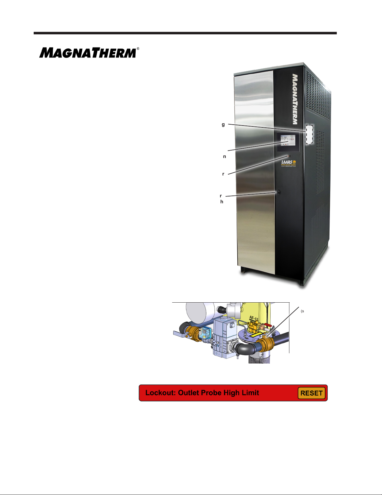
LAARS Heating Systems
Rating
Plate
Touch
Screen
For full instructions regarding the MagnaTherm,
please reference the MagnaTherm “Installation
Power
Switch
and Operation Manual”, Document #1398. If not
available at or near the MagnaTherm, it can be
downloaded at www.laars.com
Door
Latch
1. Shutting down the MagnaTherm
It may sometimes be necessary to shut down the MagnaTherm.
Here are the steps required to do this:
1. Disconnect Power at the main electrical disconnect switch.
2. Open the front access doors and close the main manual gas valve
located above heat exchanger next to blower. It has a yellow
handle
3. If freezing is anticipated, drain the MagnaTherm (also be sure to
protect the piping in the
building from freezing).
The steps listed above may require
qualied service personnel.
Gas Valve
(shown in ON position)
The Manual
Shut O for
the 3500 / 4000
Models is on
the Left side of
the unit
2. Restarting the MagnaTherm
It may be necessary to restart the MagnaTherm – for example, after a power interruption. Here are the steps
required to do this:
1 Reset any errors. See the Section 12 “Troubleshooting” of the Installation and Operating Manual.
2 Turn up the thermostat to call for heat.
3. In approximately 2 seconds, the blower will operate. Ignition should occur after 35-40 seconds. It may take
as long as 2-1/2 minutes.
4. If ignition does not occur, wait 5 minutes and then repeat steps 1 through 3.
5. If, after three attempts, the unit still does not light, shut down the unit and call your service technician.
Example
MagnaTherm User’s Manual
WARNING: If you do not follow these instructions exactly, a fire or explosion may result
causing property damage, personal injury or loss of life.
A. This appliance is equipped with an ignition device which automatically lights the pilot.
B. BEFORE OPERATING, smell all around the appliance area for gas. Be sure to smell next to
the floor because some gas is heavier than air and will settle on the floor.
WHAT TO DO IF YOU SMELL GAS
Do not try to light any appliance.
Do not touch any electric switch; do not use any phone in your building.
Immediately call your gas supplier from a neighbor’s phone. Follow the gas supplier’s instructions.
If you cannot reach your gas supplier, ca
ll the fire department.
C. Use only your hand to turn the gas valve handle. Never use tools. If the valve handle will
not turn by hand, don’t try to repair it, call a qualified service technician. Force or
attempted repair may result in a fire or explosion.
D. Do not use this appliance if any part has been under water. Immediately call a qualified
service technician to inspect the appliance and to replace any part of the control system
and any ga
s control which has been under water.
1. STOP! Read the safety information above on this label.
2. Turn off all electric power to the appliance.
3. Set the thermostat to lowest setting.
4.
5. Open front doors.
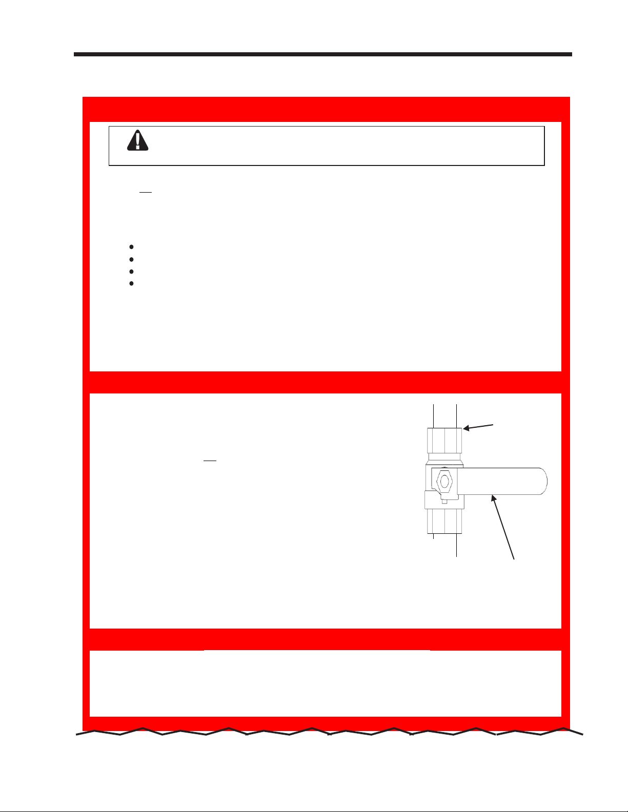
6. Turn off manual gas valve. Valve is off when valve handle is at a
right angle to gas pipe.
7. Wait five (5) minutes to clear out any gas. Then smell for gas,
including near the floor. If you do smell gas, STOP! Follow “B” in th
e
safety information above on this label. If you don’t smell gas, go to
next step.
8. Slowly turn manual gas valve to “ON”. Valve handle will be parallel to gas pipe.
9. Replace front panel.
10. Set mechanical thermostats to desired settings.
11. Turn on all electric power to the appliance.
13. If the appliance will not operate, follow the instructions “To Turn O Gas To Appliance”
12. Set operating thermostat to desired settings using boiler display.
and call your service technician or gas supplier.
1. Turn off all electric
power to the appliance if service is to be performed.
2.
Set the thermostat to lowest setting.
3.
4. Turn off manual gas valve. Valve is off when valve handle is at a right angle to gas pipe.
5.
Close front doors.
FOR YOUR SAFETY READ BEFORE OPERATING
OPERATING INSTRUCTIONS
TO TURN OFF GAS TO APPLIANCE
POUR VOTRE SÉCURITÉ, LISEZ AVANT DE METTRE EN MARCHE
Gas inlet
Manual Gas Valve
Shown in the
“OFF” Position
Do not try to light the pilot by hand.
Open front doors.
This appliance is equipped with an ignition device which automatically
lights the pilot. Do not try to light the pilot by hand.
3. Start-Up and Shut-Down Decal. Located inside the front panel.
Page 3
Continues on next page.

causing property damage, personal injury or loss of life.
11. Turn on all electric power to the appliance.
13. If the appliance will not operate, follow the instructions “To Turn O Gas To Appliance”
12. Set operating thermostat to desired settings using boiler display.
and call your service technician or gas supplier.
1. Turn off all electric
power to the appliance if service is to be performed.
2.
Set the thermostat to lowest setting.
3.
4. Turn off manual gas valve. Valve is off when valve handle is at a right angle to gas pipe.
5.
Close front doors.
A. Cet appareil est équipé d'un dispositif d'allumage qui s'allume automatiquement le pilote.
N'essayez pas de lumière le pilote à la main.
B. AVANT DE FAIRE FONCTIONNER, reniflez tout autour de l’appareil pour déceler une odeur de gaz.
Reniflez près du plancher, car certains gaz sont plus lourds que l’air et peuvent s’accumuler au niveau
du sol.
QUE FAIRE SI VOUS SENTEZ UNE ODEUR DE GAZ
Ne pas tenter d’allumer d’appareil.
Appelez immédiatement votre fournisseur de gaz depuis un voisin. Suivez les instructions du
fournisseur.
Si vous ne pouvez rejoindre le fournisseur, appelez le service des incendies.
C. N’utilisez que votre main pour fermer la soupape d’arrêt de gaz. N’utilisez jamais d’outils. Si la poignêe
de la valve ne tourne
pas manuellement, ne tentez pas de la réparer. Communiquez avec un
technicien de service qualifié. Le fait de forcer ou de tenter de réparer la poignée pourrait causer un
incendie ou une explosion.
D.
N’utilisez pas cet appareil s’il a été plongé dans I’eau, même partiellement. Faites inspecter I’appareil
par un technicien qualifié et remplacez toute partie du système de contrôle et toute commande qui ont
été plongées dans I’eau.
1. ARRÊTEZ ! Lisez les instructions de sécurité sur la portion supérieure.
2. Coupez l’alimentation électrique de l’appareil.
3. Réglez le thermostat à la temperature la plus basse.
4.
Cet appareil est équipé d'un dispositif d'allumage qui s'allume
automatiquement le pilote. N'essayez pas de lumière le pilote à la main.
5. Ouvrir les portes avant.
6. Mettez la soupape d’ arrêt de gaz à << OFF >>. La valve est en
position << OFF >> lorsque la poignée se trouve à angle droit du
tuyau de gaz.
7. Attendez cinq (5) minutes afin que le gaz se dissipe. Si vous croyez
sentir une odeur de gaz,
ARRÊTEZ ! Reportez-vous aux
instructions B ci-dessus, sur cette étiquette. S’il n’y a pas d’odeur
de gaz, passez à la prochaine étape.
8. Remettez lentement la soupape d’arrêt de gaz en position
<< ON >>. La poignée sera parallèle au tuyau de gaz.
9. Replacez le couvercle avant.
10. Set thermostats mécaniques sur les réglages désirés.
11. Rétablissez l’alimentation électrique à l’appareil.
13. Si l’appareil ne fonctionne pas, suivez les directives relatives à la fermeture de l’alimentation
en gaz et
12. Réglez le thermostat de fonctionnement désirée à l'aide paramètres affichage chaudière.
communiquez avec votre technicien de service ou le fournisseur de gaz.
1. Coupez toute alimentation électrique à l’appareil si celui-ci doit faire l’objet d’un entretien.
2.
Réglez le thermostat au réglage le plus bas.
3.
4. Mettez la soupape d’arrêt de gaz à << OFF >>. La valve est en position << OFF >> lorsque la poignée
se trouve à angle droit du tuyau de gaz.
5. Fermez les portes avant.
FOR YOUR SAFETY READ BEFORE OPERATING
OPERATING INSTRUCTIONS
TO TURN OFF GAS TO APPLIANCE
POUR VOTRE SÉCURITÉ, LISEZ AVANT DE METTRE EN MARCHE
AVERTISSEMENT: Quiconque ne respecte pas à la lettre les instructions dans la présente notice
risque un début d' incendie ou une explosion entraînant des dommages, des blessures ou la mort.
INSTRUCTIONS DE MISE EN MARCHE
Gas inlet
Manual Gas Valve
Shown in the
“OFF” Position
Entrée
de Gaz
Valve de Gaz
Manule se
Trouvant en
Position “OFF”
FERMENTURE DE L’ALIMENTATION EN GAZ
Ouvrir les portes avant.
Open front doors.
H2363600A
Page 4
LAARS Heating Systems
Start up and Shut Down Decal (continued)

MagnaTherm User’s Manual
Page 5
4. In the Event of Power Failure
The MagnaTherm will not operate during an electrical power outage. If there is an extended power outage
with danger of freezing, then the MagnaTherm (and all other water systems) should be completely drained.
Before draining the unit, turn o the gas and turn o the main power switch. When you replace the unit in
service, refer to the “Installation and Operation Manual” for instructions on lling and purging.
5. General Care
Keep the area around the MagnaTherm clear and free from combustible materials, gasoline and other
ammable vapors and liquids. Clean the jacket surfaces with a damp cloth and mild soap. Do not use
ammable cleaning materials. Keep the vent terminal free of obstructions. Do not pile snow against the vent
terminal.
6. Annual Inspection and Service
You should visually inspect the vent pipe once a year. Should any corrosion or leaks exist, have the aected
parts replaced.
Once each year a qualied service agency should conduct a detailed inspection of all ue product carrying
areas of the boiler and vent system. Follow the service instructions in the “Installation and Operating
Instructions Manual” for the MagnaTherm.
Once each year inspect the condensate drain line, vent line, condensate PVC ttings, the condensate
trap and condensate nutralizer (if installed). If neccesary, disassemble and ush with fresh water and
reassemble.
7. For Service
Contact your installing contractor, gas utility, Laars dealer, or check www.Laars.com for the nearest
authorized representative in your area.
8. About Lockouts, Holds and Alerts
The system responds to three kinds of trouble indications:
A ”lockout” is caused by a serious problem that might involve a safety issue. Once the controller enters
a lockout, the burners will shut down, and will not be allowed to run again until the cause of the problem
is corrected, and you reset the control system. See the Installation and Instruction Manual for the full list
of lockouts.
Upon lock-out due to a blocked vent condition, if possible, perform a visual inspection of the vent to verify
there is no obstruction or blockage in the vent. After visual inspection and any subsequent corrective
action, reset the blocked vent condition by pressing the “Reset” button in the navigation bar of the display.
If the blockage cannot be cleared, the lock-out does not reset, or the lock-out condition continues to
occur, contact a qualied service agency to restore the unit to normal operations.

Page 6
LAARS Heating Systems
9. Touchscreen Display
See the Installation and Operating Manual (Doc 1422) full details on all Touchscreen Control Menus.
Home Screen Active Icons
Name Icon Description
Security
Displays the current lock status icon. Touch the lock icon to lock or unlock the
Touchscreen Display.
Quick Start
Congure
Service
Messages
Active
Demands
Navigation
Bar
Provides quick access to the most commonly used parameters for easy installation.
Provices access to ALL of your congurations for a detailed setup of the unit.
Allows the service technician to access the basic diagnostic and troubleshooting
information.
Will show an 'Exclamation Point' when there is a message.
Clicking onto the Message icon will take you to the message itself.
The USB functionality will show the USB Icon at this location, if
being used.
Will show icons that indicate the active parameters that are currently in
demand.
ERROR Codes and LOCKOUTS also show in the Navigation Bar when there is one of
several unit errors or shut-downs that have occured.
Top left of every menu. The constant indicator of where you are
as you navigate into and out of the touchscreens.
Date & Time
To change date and time, simply touch the date or time and follow
the directions.

MagnaTherm User’s Manual
Typical Numeric Keypad Menu
NOTE: You can always tell exactly where you have navigated to
by looking at the icons in the Navigation Bar.
In this example you are in
Home / Congure / Central Heat / Central Heat One
Page 7
Shows the current setting of
the Parameter.
These windows will reect
the allowable ranges of the
parameter
To delete the current setting
before entering in the new
value.
“Up and Down” arrows are
used to increment the setting
accordingly.
Remember to always save the new setting with the button.
Typical Selection Screen
The “Back” button jumps to the previous screen.
The “Enter” button is used to
accept the new value.
This is the indicator that will
be shown when the correct
password has been entered to
allow the setting to change.
The highlighted button
(orange) shows which one
is selected. Some screens
may only allow you to set
one or the other, while some
other screens (example:
pump selection) will allow
you to select any or all of the
options.

Page 8
LAARS Heating Systems
CAUTION
Do not use this boiler if any part has been under water.
Immediately call a qualied service technician to inspect the
boiler. Any part of the control system and any gas control
which has been under water must be replaced.
N’utilisez pas cette chaudière si une partie a été sous l’eau.
Appelez immédiatement un technicien de service qualié pour
inspecter la chaudière. Toute partie du système de contrôle
et toute commande qui ont été plongées dans l’eau doit être
remplacé
WARNING
If the unit overheats or the gas supply fails to shut o, do
not turn o or disconnect the electrical supply to the pump.
Instead, shut o the gas supply at a location external to the
MagnaTherm.
En cas de surchaue ou si l’admission de gaz ne peut être
coupée, ne pas couper ni débrancher l’alimentation électrique
de la pompe. Fermer plutôt le robinet d’admission de gaz à
l’extérieur de l’appareil.
A
S
M
E
H
A
S
M
E
HLW
H2397200
Customer Service and Product Support: 800.900.9276 • Fax 800.559.1583
Headquarters: 20 Industrial Way, Rochester, NH 03867 • 603.335.6300 • Fax 603.335.3355
1869 Sismet Road, Mississauga, Ontario, Canada L4W 1W8 • 905.238.0100 • Fax 905.366.0130
www.Laars.com Printed in U.S.A. © Laars Heating Systems 1904 Document 1423
 Loading...