

Page 1

PP45 5.7" LCD m touch screen • Order data
3. PP45 5.7" LCD m touch screen
3.1 Order data
Model number Short description Figure
4PP045.0571-042 Power Panel PP45, touch screen, 5.7" QVGA m LCD, backlighting,
Required accessories
0TB103.9 Accessory terminal block 3-pin, screw clamp, 3.31 mm², protection
0TB103.91 Accessory terminal block 3-pin, cage clamp, 3.31 mm², protection
0TB704.9 Accessory terminal block, 4-pin, screw clamp, 1.5 mm²
0TB704.91 Accessory terminal block, 4-pin, cage clamp, 2.5 mm²
0AC201.9 Lithium batteries, 5 pcs., 3 V / 950 mAh, button cell
4A0006.00-000 Lithium battery, 3 V / 950 mAh, button cell
4A0064.00-000 5 DIN A4 legend sheets , 16 fields for a total of 40 devices,
5CFCRD.0064-03 CompactFlash 64 MB ATA/IDE SiliconSystems
5CFCRD.0128-03 CompactFlash 128 MB ATA/IDE SiliconSystems
5CFCRD.0256-03 CompactFlash 256 MB ATA/IDE SiliconSystems
5CFCRD.0512-03 CompactFlash 512 MB ATA/IDE SiliconSystems
5CFCRD.1024-03 CompactFlash 1024 MB ATA/IDE SiliconSystems
5CFCRD.2048-03 CompactFlash 2048 MB ATA/IDE SiliconSystems
5CFCRD.4096-03 CompactFlash 4096 MB ATA/IDE SiliconSystems
5CFCRD.8192-03 CompactFlash 8192 MB ATA/IDE SiliconSystems
Optional accessories
4PP045.IF10-1 PP45 interface module, 1 RS232 interface
4PP045.IF23-1 2005 Interface Module, 1 RS485/RS422 interface (RS422:
4PP045.IF24-1 PP45 interface module, 1 Profibus DP slave interface (electrically
4PP045.IF33-1 PP45 interface module, 2 CAN (electrically isolated and network
10 touch keys, 64 MB DRAM, 32 KB SRAM, x86 100 MHz Intel
compatible, removable application memory (CompactFlash),
Ethernet 10/100, X2X Link, 2 x USB, IP 65 protection (front side).
Application memory must be ordered separately!
Order TB103 and TB704 terminal blocks separately.
against vibration with the screw flange.
against vibration with the screw flange.
CorelDraw template can be downloaded online.
electrically isolated, RS485: electrically isolated and network
capable), 1 CAN interface (electrically isolated and network
capable).
isolated and network capable), 1 RS232/RS422/RS485 interface
(RS422/RS485: electrically isolated and network-capable)
capable).
Table 5: PP45 LCD m touch screen - Order data
24
Power Panel 45 User's Manual V 1.00
Page 2

PP45 5.7" LCD m touch screen • Technical data
3.2 Technical data
Product ID PP45 LCD m touch screen
Controller
Processor ELAN SC520 100 MHz, Intel compatible
Main memory 64 MB DRAM
SRAM 32 KB, battery-backup
CompactFlash slot 1 slot for Type I CompactFlash card
Insert slot for PP45 interface modules 1
Watchdog Internal system management controller
Power failure logic System management controller, 10 ms buffer time
Battery Lithium, 950 mAh, can be exchanged from the outside
Real-time clock Battery-buffered
Mode/node switches 2, 16 digits each
Display
Type LCD monochrome
Colors 8 shades of gray
Resolution QVGA, 320 x 240 pixels
Diagonal 5.7"
Brightness 140 cd/m²
Half-brightness time 55,000 h
Front Multi-layered cover with insertion slots for key labels
Keys
Touch keys 10 (labeled with legend sheets)
Interfaces
USB 2 x USB 2.0, type A connection
Ethernet RJ 45 Twisted Pair (10 BaseT / 100 BaseT)
X2X X2X Link master
24 VDC supply
Input voltage 24 VDC ± 25%
General information
Power consumption Max. 8 W
Certification CE, C-UL-US, GOST-R (in development)
Operational conditions
Operating temperature 0 to +50°C
Relative humidity 10% to 90%, non-condensing
Protection type IP65 (front side) / IP20 (back side)
Table 6: PP45 LCD m touch screen - Technical data
Chapter 2
Power Panel 45
25Power Panel 45 User's Manual V 1.00
Page 3

PP45 5.7" LCD m touch screen • Additional technical data
Product ID PP45 LCD m touch screen
Storage and transport conditions
Temperature -20°C to +70°C
Relative humidity T ≤ 40°C: 5% to 90%, non-condensing
Mechanical characteristics
Outer dimensions (W x H x D [mm]) 203 x 145 x 56.4
Weight 0.5 kg
T > 40°C: < 90%, non-condensing
Table 6: PP45 LCD m touch screen - Technical data
3.3 Additional technical data
Product ID PP45 LCD m touch screen
Controller
Battery buffer current Max. 30 µA
Real-time clock resolution 1 s
Operating system Automation Runtime
24 VDC supply
Input voltage (min./nom./max.) 18 VDC / 24 VDC / 30 VDC
Voltage monitoring An NMI is triggered if the input voltage falls below 15 VDC.
General information
B&R ID code $1FB4
Table 7: PP45 LCD m touch screen - Additional technical data
26
Power Panel 45 User's Manual V 1.00
Page 4

PP45 5.7" LCD m touch screen • Diagnostic LEDs
ACT
(orange)
LNK
(green)
3.4 Diagnostic LEDs
There are four diagnostic LEDs on the back of the PP45:
Figure 1: PP45 LCD m touch screen - Diagnostic LEDs
LED Color Status Description
Status Red On Error / Reset
Green On RUN
Orange On Boot, Service or Diagnostics mode
Green on / Orange blinking RUN, battery not OK
User Green - This LED can be operated by the user (with the AsHW library). This function is supported by
X2X Orange On The module sends data via the X2X Link interface.
CF Orange On Access to the CompactFlash card
Table 8: PP45 LCD m touch screen - Diagnostic LEDs
Automation Runtime starting with Version N2.90 / A2.92.
Chapter 2
Power Panel 45
There are two more LEDs right next to the Ethernet interface:
Figure 2: PP45 LCD m touch screen - Ethernet LEDs
LED Color Status Description
ACT Orange On No Ethernet activity on bus
Blinking Ethernet activity on bus
LNK Green On A link to the remote station has been established.
Table 9: PP45 LCD m touch screen - Diagnostic LEDs
27Power Panel 45 User's Manual V 1.00
Page 5

PP45 5.7" LCD m touch screen • Connection elements
Supply voltage
Ethernet interface
USB interfaces
X2X Link interface
X2X
X2X^
X2X\\
SHLD
1234
3.5 Connection elements
Figure 3: PP45 LCD m touch screen - Connection elements
3.5.1 X2X Link interface
Interface Pin assignments
Application interface
X2X Link
Terminal X2X Link
1 X2X X2X data
2 X2X⊥ X2X ground
3 X2X\ X2X data inverted
4 SHLD Shield
Required accessories
0TB704.9 Accessory terminal block, 4-pin, screw clamp, 1.5 mm²
0TB704.91 Accessory terminal block, 4-pin, cage clamp, 2.5 mm²
28
4-pin multipoint connector
Table 10: PP45 LCD m touch screen - Pin assignments - X2X Link
Power Panel 45 User's Manual V 1.00
Page 6

PP45 5.7" LCD m touch screen • Connection elements
USB Port 1
USB Port 2
3.5.2 USB interface
This Power Panel 45 device has a USB 2.0 (Universal Serial Bus) host controller with two USB
ports, which are easily accessible for the user.
USB interface
Chapter 2
Power Panel 45
Transfer rate
Power supply Max. 500 mA per port
1)
1) The actual value depends on the operating system or diver being used.
2) For safety, every USB port is equipped with a maintenance free "USB current-limiting circuit breaker" (max. 500 mA)
Low speed (1.5 MBit/s), full speed (12 MBit/s), to high speed (480 Mbit/s)
2)
Table 11: PP45 LCD m touch screen - USB interface
Warning!
Peripheral USB devices can be connected to the USB interfaces. Due to the vast
number of USB devices available on the market, B&R cannot guarantee their
performance. B&R does assure the performance of all USB devices that they
provide.
Important!
Because of general PC specifications, this interface should be handled with extreme
care with regard to EMC, location of cables, etc.
29Power Panel 45 User's Manual V 1.00
Page 7

PP45 5.7" LCD m touch screen • Connection elements
1
3.5.3 Ethernet Interface
Interface Pin assignments
Terminal
Ethernet interface
RJ45 twisted pair socket
(10BaseT/100BaseT)
1 RXD Receive signal
2 RXD\ Receive signal inverted
3 TXD Transmit signal
4 Termination Termination
5 Termination Termination
6 TXD\ Transmit signal inverted
7 Termination Termination
8 Termination Termination
Table 12: PP45 LCD m touch screen - Pin assignments - Ethernet interface
3.5.4 Supply voltage
The pin assignments can be found either in the following table or printed on the back of the
Power Panel. The Power Panel has reverse polarity protection that prevents the supply voltage
from being connected incorrectly, which would damage the device. Overload protection must be
provided by an external fuse (5 A, fast-acting).
Supply voltage Pin assignments
Terminal Assignment
+ 24 VDC
Functional grounding
GND
Required accessories
0TB103.9 Accessory terminal block 3-pin, screw clamp, 3.31 mm², protection
3-pin multipoint connector
0TB103.91 Accessory terminal block 3-pin, cage clamp, 3.31 mm², protection against
Table 13: PP45 LCD m touch screen - Pin assignments - Supply voltage
against vibration with the screw flange.
vibration with the screw flange.
Important!
The pin's connection to the functional ground (e.g. switching cabinet) should be as
short as possible. We recommend using the largest possible conductor cross
section on the supply plug.
30
Power Panel 45 User's Manual V 1.00
Page 8
PP45 5.7" LCD m touch screen • Operating mode and node number switches
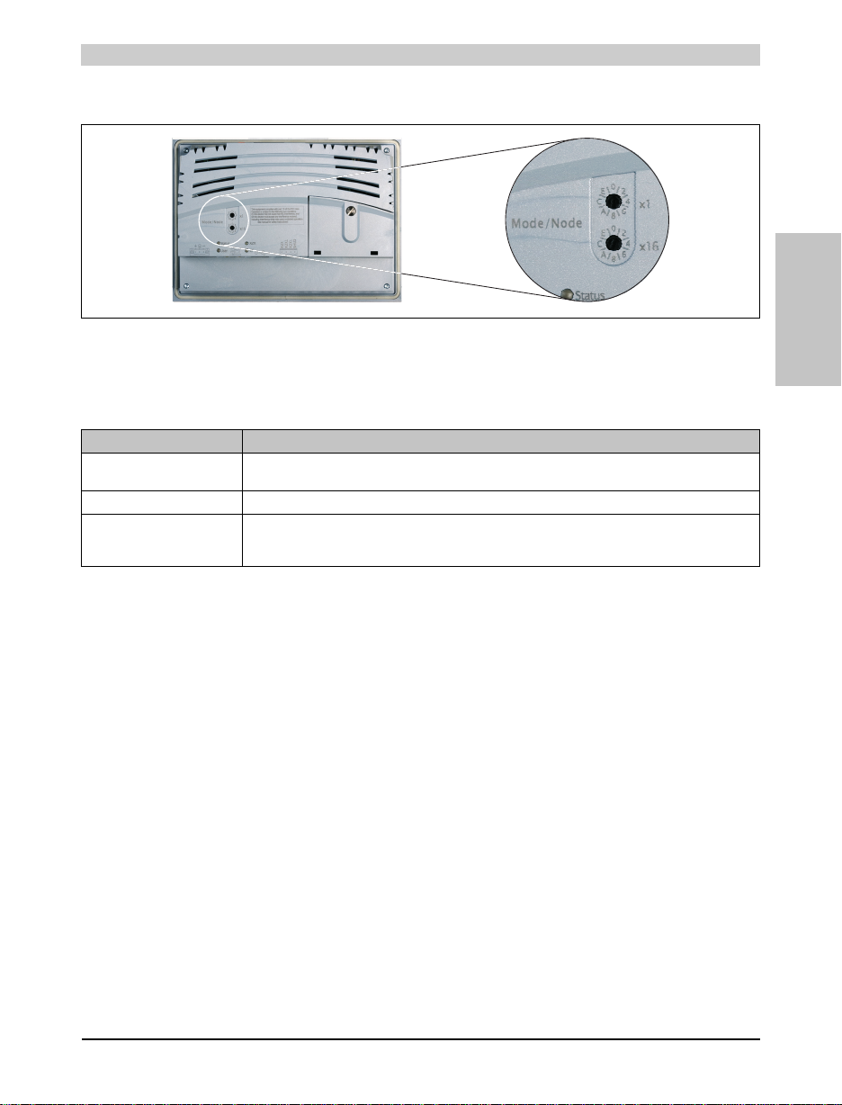
3.6 Operating mode and node number switches
Figure 4: PP45 LCD m touch screen - Operating mode and node number switches
The Power Panel 45 device is equipped with 2 hex switches, which are used as operating mode
or node number switches. Switch positions 01 - FE are used to set the INA station number of the
Ethernet interface.
Switch position Description
00 Boot mode:
01 - FE INA node number of the Ethernet interface
FF Diagnostics mode:
Table 14: PP45 LCD m touch screen - Switch positions of the operating mode and node number switches
The CPU is started in boot mode.
The CPU boots in Diagnostics mode. Program sections in User RAM and User FlashPROM are not initialized.
After diagnostics mode, the CPU always boots with a cold restart.
Chapter 2
Power Panel 45
31Power Panel 45 User's Manual V 1.00
Page 9

PP45 5.7" LCD m touch screen • Dimensions
203
145
30
28
4.7
51.7
109.5
184.5
195.5
137.5
126.5
3.7 Dimensions
Figure 5: PP45 LCD m touch screen - Dimensions
Installation cutout: 186.1 mm x 128.1 mm
32
Power Panel 45 User's Manual V 1.00
 Loading...