

Page 1
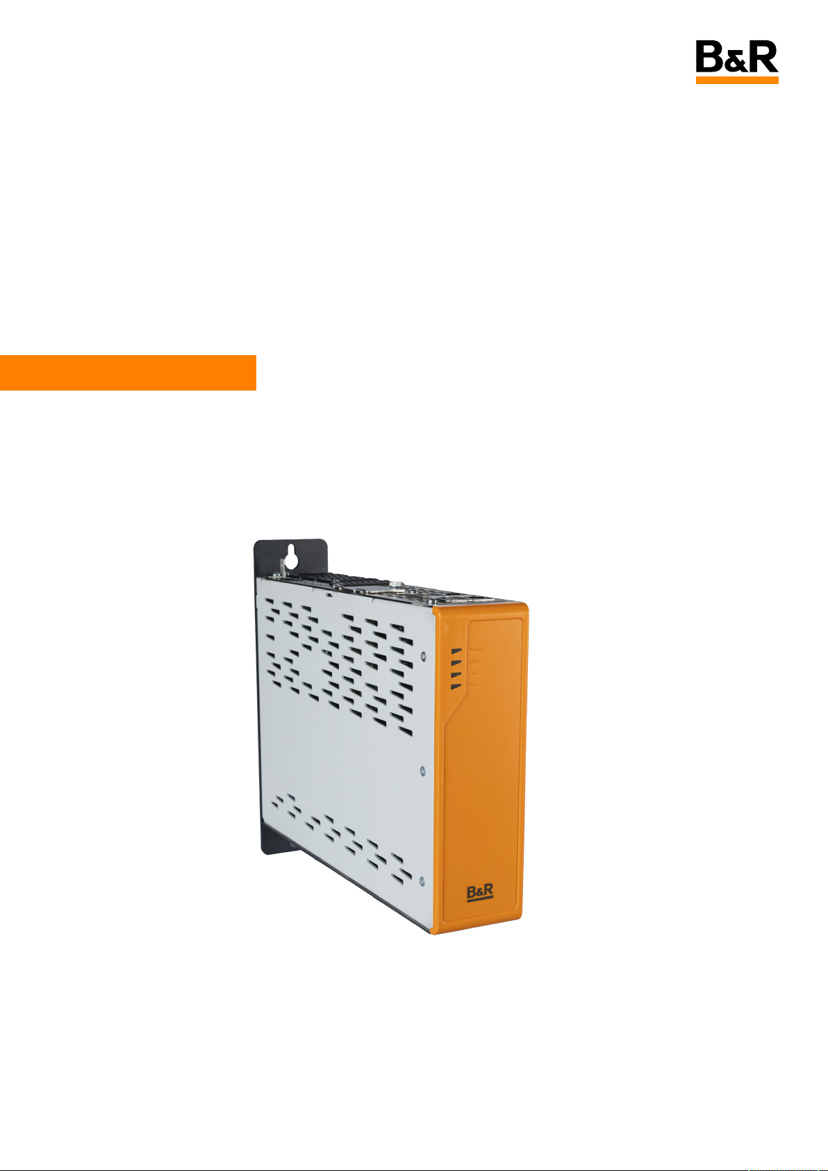
Automation PC 3200
User's manual
1.00 (March 2025)
MAAPC3200
Translation of the original documentation
Page 2

Publishing information
B&R Industrial Automation GmbH
B&R Strasse 1
5142 Eggelsberg
Austria
Telephone: +43 7748 6586-0
Fax: +43 7748 6586-26
Disclaimer
All information in this document is current as of its creation. The contents of this document are subject to
change without notice. B&R Industrial Automation GmbH assumes unlimited liability in particular for technical or editorial errors in this document only (i) in the event of gross negligence or (ii) for culpably inflicted
personal injury. Beyond that, liability is excluded to the extent permitted by law. Liability in cases in which
the law stipulates mandatory unlimited liability (such as product liability) remains unaffected. Liability for
indirect damage, consequential damage, business interruption, loss of profit or loss of information and
data is excluded, in particular for damage that is directly or indirectly attributable to the delivery, performance and use of this material.
B&R Industrial Automation GmbH notes that the software and hardware designations and brand names
of the respective companies used in this document are subject to general trademark, brand or patent protection.
Hardware and software from third-party suppliers referenced in this document is subject exclusively to the
respective terms of use of these third-party providers. B&R Industrial Automation GmbH assumes no liability in this regard. Any recommendations made by B&R Industrial Automation GmbH are not contractual
content, but merely non-binding information for which no liability is assumed. When using hardware and
software from third-party suppliers, the relevant user documentation of these third-party suppliers must
additionally be consulted and, in particular, the safety guidelines and technical specifications contained
therein must be observed. The compatibility of the products from B&R Industrial Automation GmbH described in this document with hardware and software from third-party suppliers is not contractual content
unless this has been separately agreed in individual cases; in this respect, warranty for such compatibility is
excluded in any case, and it is the sole responsibility of the customer to verify this compatibility in advance.
1683466188250-1.00
2 Automation PC 3200 User's manual V1.00
Page 3

Table of contents
1 Introduction................................................................................................................ 8
1.1 Manual history........................................................................................................................................................... 8
1.2 Information about this document........................................................................................................................ 9
1.2.1 Organization of notices..................................................................................................................................... 9
1.2.2 Guidelines............................................................................................................................................................. 9
2 General safety guidelines....................................................................................... 10
2.1 Intended use............................................................................................................................................................ 10
2.2 Protection against electrostatic discharge...................................................................................................... 10
2.2.1 Packaging............................................................................................................................................................10
2.2.2 Regulations for proper ESD handling...........................................................................................................10
2.3 Regulations and measures....................................................................................................................................11
2.4 Transport and storage.......................................................................................................................................... 11
2.5 Installation................................................................................................................................................................ 11
2.6 Operation..................................................................................................................................................................12
2.6.1 Protection against contact with electrical parts....................................................................................... 12
2.6.2 Ambient conditions - Dust, moisture, aggressive gases......................................................................... 12
2.6.3 Programs, viruses and malicious programs............................................................................................... 12
2.7 Cybersecurity disclaimer for products............................................................................................................... 13
3 System overview...................................................................................................... 14
3.1 Configuration...........................................................................................................................................................14
3.1.1 Order number key..............................................................................................................................................15
3.2 Overview................................................................................................................................................................... 16
4 Technical data.......................................................................................................... 18
4.1 Complete system....................................................................................................................................................18
4.1.1 Connection options.......................................................................................................................................... 18
4.1.1.1 DP operation.................................................................................................................................................18
4.1.1.2 SDL4 operation............................................................................................................................................20
4.1.2 Product information......................................................................................................................................... 21
4.1.2.1 Identification................................................................................................................................................ 21
4.1.3 Mechanical properties..................................................................................................................................... 22
4.1.3.1 Dimensions................................................................................................................................................... 22
4.1.3.2 Spacing for air circulation.........................................................................................................................23
4.1.3.3 Mounting orientations...............................................................................................................................24
4.1.3.4 Weight specifications................................................................................................................................ 24
4.1.4 Environmental properties...............................................................................................................................25
4.1.4.1 Temperature specifications......................................................................................................................25
4.1.4.2 Relative humidity.........................................................................................................................................31
4.1.4.3 Vibration and shock................................................................................................................................... 32
4.1.4.4 Degree of protection................................................................................................................................. 32
4.1.5 Electrical properties......................................................................................................................................... 33
4.1.5.1 Block diagram.............................................................................................................................................. 33
4.1.5.2 Power calculation........................................................................................................................................34
4.1.6 Device interfaces and slots............................................................................................................................36
4.1.6.1 Device interface overview......................................................................................................................... 36
4.1.6.2 +24 VDC power supply.............................................................................................................................. 37
4.1.6.3 Ethernet interfaces.................................................................................................................................... 38
4.1.6.4 USB interfaces.............................................................................................................................................38
4.1.6.5 CFexpress slots...........................................................................................................................................39
4.1.6.6 Battery.......................................................................................................................................................... 40
4.1.6.7 LED status indicators.................................................................................................................................41
4.1.6.8 IF options..................................................................................................................................................... 42
4.1.6.9 DisplayPort interface................................................................................................................................. 42
4.1.6.10 Power and reset buttons........................................................................................................................ 43
4.1.6.11 Trusted Platform Module (TPM)............................................................................................................ 43
Automation PC 3200 User's manual V1.00 3
Page 4

Table of contents
4.2 Individual components......................................................................................................................................... 44
4.2.1 System units......................................................................................................................................................44
4.2.1.1 5APC3200.RPLx-000................................................................................................................................... 44
4.2.2 Main memory.................................................................................................................................................... 48
4.2.2.1 5MMDDR.xxxx-0x........................................................................................................................................ 48
4.2.3 Graphics options.............................................................................................................................................. 49
4.2.3.1 5ACCLI02.DPO0-000.................................................................................................................................. 49
4.2.3.2 5ACCLI02.SD40-000................................................................................................................................... 51
4.2.4 Interface options..............................................................................................................................................53
4.2.4.1 5AC901.I232-00............................................................................................................................................53
4.2.4.2 5AC901.I485-00...........................................................................................................................................55
4.2.4.3 5AC901.ICAN-01.......................................................................................................................................... 58
4.2.4.4 5AC901.IETH-00.......................................................................................................................................... 61
4.2.4.5 5AC901.IHDA-00......................................................................................................................................... 63
4.2.4.6 5AC901.ISRM-00......................................................................................................................................... 65
4.2.4.7 5AC901.IPLK-00........................................................................................................................................... 67
4.2.4.8 5AC901.IRDY-00.......................................................................................................................................... 69
4.2.4.9 5AC901.ISIO-00........................................................................................................................................... 70
4.2.4.10 5ACCIF02.CANE-000................................................................................................................................ 72
4.2.4.11 5ACCIF02.FPLK-000..................................................................................................................................76
4.2.4.12 5ACCIF02.FPLS-000..................................................................................................................................78
4.2.4.13 5ACCIF02.FPSC-000................................................................................................................................. 81
4.2.4.14 5ACCIF02.ISS0-000.................................................................................................................................. 85
4.2.4.15 5ACCIF04.FPLK-000.................................................................................................................................88
4.2.5 Mass storage options..................................................................................................................................... 90
4.2.5.1 5ACCMS01.MDT2-000................................................................................................................................90
4.2.5.2 5ACCMSM2.xxxx-000................................................................................................................................. 92
4.2.6 Uninterruptible power supply....................................................................................................................... 94
4.2.6.1 5AC901.IUPS-0x...........................................................................................................................................94
4.2.6.2 5AC901.BUPS-0x......................................................................................................................................... 96
4.2.6.3 5CAUPS.xxxx-01........................................................................................................................................ 100
4.2.7 Front covers..................................................................................................................................................... 102
4.2.7.1 5ACCFF01.0000-00x................................................................................................................................. 102
4.2.8 CFexpress cards............................................................................................................................................. 103
4.2.8.1 Order data.................................................................................................................................................. 103
5 Installation and wiring..........................................................................................104
5.1 Basic information................................................................................................................................................. 104
5.1.1 Installing the Automation PC....................................................................................................................... 106
5.1.1.1 Procedure.................................................................................................................................................... 106
5.1.2 Installation information for individual deliveries / individual components....................................... 106
5.2 Connecting to the power grid.......................................................................................................................... 106
5.2.1 Installing the DC power cable......................................................................................................................106
5.2.1.1 Wiring........................................................................................................................................................... 107
5.2.2 Connecting the power supply to a B&R device........................................................................................107
5.2.3 Grounding concept - Functional ground...................................................................................................108
5.2.4 Connecting cables..........................................................................................................................................108
6 Commissioning...................................................................................................... 109
6.1 Switching on the device for the first time..................................................................................................... 109
6.2 General instructions about the procedure for temperature testing......................................................... 110
6.2.1 Procedure..........................................................................................................................................................110
6.2.2 Evaluating temperatures in Windows operating systems.....................................................................110
6.2.2.1 Evaluating with HMI Monitor..................................................................................................................110
6.2.2.2 Evaluation with BurnInTest from PassMark........................................................................................ 110
6.3 Evaluating the measurement results............................................................................................................... 112
6.4 Known problems / Characteristics...................................................................................................................112
4 Automation PC 3200 User's manual V1.00
Page 5

Table of contents
7 Software.................................................................................................................. 113
7.1 UEFI BIOS options................................................................................................................................................. 113
7.1.1 Overview of BIOS description....................................................................................................................... 113
7.1.2 BIOS Setup and startup procedure............................................................................................................. 114
7.1.2.1 Input options...............................................................................................................................................114
7.1.3 Boot menu.........................................................................................................................................................116
7.1.4 Boot Manager................................................................................................................................................... 117
7.1.5 Device Manager................................................................................................................................................118
7.1.5.1 Intel(R) Rapid Storage Technology........................................................................................................ 118
7.1.6 Setup Utility..................................................................................................................................................... 120
7.1.6.1 Main.............................................................................................................................................................. 120
7.1.6.2 Advanced..................................................................................................................................................... 122
7.1.6.3 Security........................................................................................................................................................ 142
7.1.6.4 Power........................................................................................................................................................... 143
7.1.6.5 Boot..............................................................................................................................................................144
7.1.6.6 Exit............................................................................................................................................................... 146
7.2 RAID configuration............................................................................................................................................... 147
7.2.1 UEFI RAID.......................................................................................................................................................... 147
7.2.1.1 Configuration with the internal RAID controller................................................................................. 147
7.2.1.2 Create RAID Volume..................................................................................................................................148
7.2.1.3 Delete RAID Volume.................................................................................................................................. 148
7.2.1.4 Reset Disks to Non-RAID......................................................................................................................... 149
7.3 Upgrade information........................................................................................................................................... 150
7.3.1 UEFI BIOS upgrade......................................................................................................................................... 150
7.3.1.1 BIOS upgrade..............................................................................................................................................150
7.3.1.2 Procedure in the EFI shell........................................................................................................................150
7.3.2 PC firmware upgrade......................................................................................................................................151
7.3.2.1 Procedure in Windows (ADI Control Center)........................................................................................151
7.3.2.2 Procedure in the EFI shell........................................................................................................................ 151
7.3.2.3 Automatic firmware upgrade..................................................................................................................151
7.3.2.4 Firmware upgrade with Automation Runtime.................................................................................... 152
7.3.3 Automation Panel firmware upgrade......................................................................................................... 153
7.3.3.1 Procedure in Windows (ADI Control Center)....................................................................................... 153
7.3.3.2 Procedure in the EFI shell........................................................................................................................153
7.4 Operating systems...............................................................................................................................................154
7.4.1 Windows 10 IoT Enterprise 2021 LTSC....................................................................................................... 154
7.4.1.1 General information.................................................................................................................................. 154
7.4.1.2 Order data.................................................................................................................................................. 154
7.4.1.3 Overview......................................................................................................................................................154
7.4.1.4 Features...................................................................................................................................................... 154
7.4.1.5 Installation.................................................................................................................................................. 155
7.4.1.6 Drivers..........................................................................................................................................................155
7.4.1.7 Activation.....................................................................................................................................................155
7.4.1.8 Supported display resolutions...............................................................................................................155
7.4.2 Windows 10 Recovery Solution.................................................................................................................... 156
7.4.3 Linux for B&R 12 (GNU/Linux)...................................................................................................................... 157
7.4.3.1 General information.................................................................................................................................. 157
7.4.3.2 Order data.................................................................................................................................................. 157
7.4.3.3 Overview......................................................................................................................................................157
7.4.3.4 Features...................................................................................................................................................... 157
7.4.3.5 Installation.................................................................................................................................................. 157
7.4.3.6 Drivers..........................................................................................................................................................157
7.4.4 B&R Live Utils.................................................................................................................................................. 158
7.5 Automation software...........................................................................................................................................159
7.5.1 Licensing........................................................................................................................................................... 159
7.5.2 Order data........................................................................................................................................................ 159
7.5.3.1 Support.......................................................................................................................................................... 160
Automation PC 3200 User's manual V1.00 5
Page 6

Table of contents
7.5.4 Automation Runtime..................................................................................................................................... 160
7.5.4.1 General information................................................................................................................................. 160
7.5.4.2 Minimum versions.................................................................................................................................... 160
7.5.5 B&R Hypervisor................................................................................................................................................ 161
7.5.6 mapp Technology........................................................................................................................................... 162
7.6 Automation Device Interface (ADI)................................................................................................................... 163
7.6.1 ADI driver (Windows)......................................................................................................................................163
7.6.1.1 Control Center............................................................................................................................................163
7.6.1.2 HMI Monitor................................................................................................................................................163
7.6.1.3 HMI Report..................................................................................................................................................164
7.6.2 ADI Development Kit (Windows)................................................................................................................. 165
7.6.3 ADI .NET SDK (Windows).............................................................................................................................. 166
7.7 Key Editor................................................................................................................................................................167
7.8 KCF Editor.............................................................................................................................................................. 168
7.9 HMI Service Center...............................................................................................................................................169
8 Maintenance........................................................................................................... 170
8.1 Changing the battery.......................................................................................................................................... 170
8.1.1 Procedure for replacing the battery........................................................................................................... 170
8.2 Replacing a CFexpress card............................................................................................................................... 172
8.3 Installing the interface option and DDR4 SDRAM......................................................................................... 173
8.3.1 Installing M.2 mass storage devices...........................................................................................................176
8.4 Installing and connecting the UPS battery unit.............................................................................................177
8.4.1 Permissible mounting orientations............................................................................................................ 177
8.5 Cleaning.................................................................................................................................................................. 178
8.6 Repairs/Complaints and replacement parts..................................................................................................178
9 Accessories............................................................................................................. 179
9.1 General information............................................................................................................................................. 179
9.1.1 Replacement parts and sets.........................................................................................................................179
9.2 Installation accessories...................................................................................................................................... 180
9.2.1 Order data........................................................................................................................................................180
9.3 Terminal block power supply.............................................................................................................................181
9.3.1 0TB103.9x..........................................................................................................................................................181
9.3.1.1 General information.................................................................................................................................. 181
9.3.1.2 Order data...................................................................................................................................................181
9.3.1.3 Technical data............................................................................................................................................ 181
9.4 Replacement CMOS batteries........................................................................................................................... 182
9.4.1 0AC201.91 / 4A0006.00-000........................................................................................................................182
9.4.1.1 General information..................................................................................................................................182
9.4.1.2 Order data.................................................................................................................................................. 182
9.4.1.3 Technical data........................................................................................................................................... 182
9.5 Terminal block for IF options............................................................................................................................ 183
9.5.1 0TB1210.3100....................................................................................................................................................183
9.5.1.1 General information..................................................................................................................................183
9.5.1.2 Order data.................................................................................................................................................. 183
9.5.1.3 Technical data............................................................................................................................................183
9.6 Terminal block ready relay.................................................................................................................................184
9.6.1 0TB2104.8000..................................................................................................................................................184
9.6.1.1 General information................................................................................................................................. 184
9.6.1.2 Order data.................................................................................................................................................. 184
9.6.1.3 Technical data........................................................................................................................................... 184
9.7 USB mass storage device................................................................................................................................... 184
9.8 CFexpress cards................................................................................................................................................... 184
9.9 Cables..................................................................................................................................................................... 184
6 Automation PC 3200 User's manual V1.00
Page 7

Table of contents
10 International and national certifications......................................................... 185
10.1 Directives and declarations.............................................................................................................................. 185
10.1.1 CE marking......................................................................................................................................................185
10.1.2 EMC Directive.................................................................................................................................................185
10.1.3 UKCA................................................................................................................................................................ 185
11 Environmentally friendly disposal..................................................................... 186
11.1 Separation of materials..................................................................................................................................... 186
Appendix A Maintenance Controller Extended (MTCX)....................................... 187
Appendix B Cable data.............................................................................................188
B.1 RS232 - Bus length and cable type...................................................................................................................188
B.2 RS422 - Bus length and cable type.................................................................................................................. 188
B.3 RS485 - Bus length and cable type.................................................................................................................. 189
B.4 CAN - Bus length and cable type..................................................................................................................... 189
Appendix C POWERLINK.......................................................................................... 190
C.1 LED "S/E" (status/error LED)............................................................................................................................190
C.1.1 Ethernet mode................................................................................................................................................ 190
C.1.2 POWERLINK V2 mode.................................................................................................................................... 190
C.1.3 System stop error codes.............................................................................................................................. 192
C.1.4 POWERLINK V2................................................................................................................................................ 192
Appendix D Reading LED status indicators.......................................................... 193
Appendix E Abbreviations....................................................................................... 194
Automation PC 3200 User's manual V1.00 7
Page 8

Introduction
1 Introduction
Information:
B&R makes every effort to keep documents as current as possible. The most current versions are available for download on the B&R website (www.br-automation.com).
1.1 Manual history
Version Date Comment
1.00 March 2025 First edition
1) Editorial changes are not listed.
1)
8 Automation PC 3200 User's manual V1.00
Page 9
Introduction
1.2 Information about this document
Information:
This document is not intended for end customers! The safety guidelines required for end
customers must be incorporated into the operating instructions for end customers in the
respective national language by the machine manufacturer or system provider.
1.2.1 Organization of notices
Safety notices
Contain only information that warns of dangerous functions or situations.
Signal word Description
Danger! Failure to observe these safety guidelines and notices will result in death, severe injury or substantial damage
Warning! Failure to observe these safety guidelines and notices can result in death, severe injury or substantial damage
Caution! Failure to observe these safety guidelines and notices can result in minor injury or damage to property.
Notice! Failure to observe these safety guidelines and notices can result in damage to property.
General notices
Contain useful information for users and instructions for avoiding malfunctions.
Signal word Description
Information: Useful information, application tips and instructions for avoiding malfunctions.
to property.
to property.
1.2.2 Guidelines
European dimension standards apply to all dimension diagrams.
Information:
All specifications in dimension diagrams and associated tables are in millimeters [mm].
Unless otherwise specified, the following general
tolerances apply:
Nominal dimension range General tolerance per
DIN ISO 2768 medium
Up to 6 mm ±0.1 mm
Over 6 to 30 mm ±0.2 mm
Over 30 to 120 mm ±0.3 mm
Over 120 to 400 mm ±0.5 mm
Over 400 to 1000 mm ±0.8 mm
Automation PC 3200 User's manual V1.00 9
Page 10

General safety guidelines
2 General safety guidelines
2.1 Intended use
In all cases, applicable national and international standards, regulations and safety measures must be taken
into account and observed!
The B&R products described in this manual are intended for use in industry and industrial applications.
Intended use includes controlling, operating, monitoring, driving and visualizing as part of automation
processes in machines and systems.
The use of B&R products is only permitted in their original condition. Modifications and extensions are only
permitted if they are described in this manual.
B&R assumes no any liability for damages of any kind arising from the use of B&R products outside of their
intended use.
B&R products were not designed, developed and manufactured for any use involving serious risks or hazards
that could result in death, injury, serious physical impairment or loss of any kind without the implementation
of exceptionally stringent safety precautions.
B&R products are explicitly not intended for use in the following applications:
•
Monitoring and controlling thermonuclear processes
•
Controlling weapon systems
•
Flight and traffic management systems for passenger and freight transportation
•
Health monitoring and life support systems
2.2 Protection against electrostatic discharge
Electrical assemblies that can be damaged by electrostatic discharge (ESD) must be handled accordingly.
2.2.1 Packaging
•
Electrical assemblies with housing:
Do not require special ESD packaging but must be handled properly (see "Electrical assemblies with
housing").
•
Electrical assemblies without housing:
Are protected by ESD-suitable packaging.
2.2.2 Regulations for proper ESD handling
Electrical assemblies with housing
•
Do not touch the connector contacts of connected cables.
•
Do not touch the contact tips on circuit boards.
10 Automation PC 3200 User's manual V1.00
Page 11

General safety guidelines
Electrical assemblies without housing
The following applies in addition to "Electrical assemblies with housing":
•
All persons handling electrical assemblies and devices in which electrical assemblies are installed must
be grounded.
•
Assemblies are only permitted to be touched on the narrow sides or front plate.
•
Always place assemblies on suitable surfaces (ESD packaging, conductive foam, etc.). Metallic surfaces
are not suitable surfaces!
•
Assemblies must not be subjected to electrostatic discharges (e.g. due to charged plastics).
•
A minimum distance of 10 cm from monitors or television sets must be maintained.
•
Measuring instruments and devices must be grounded.
•
Test probes of floating potential measuring instruments must be discharged briefly on suitable
grounded surfaces before measurement.
Individual components
•
ESD protective measures for individual components are implemented throughout B&R (conductive
floors, shoes, wrist straps, etc.).
•
The increased ESD protective measures for individual components are not required for handling B&R
products at customer locations.
2.3 Regulations and measures
Electronic devices are generally not failsafe. If the programmable logic controller, operating or control device or uninterruptible power supply fails, the user is responsible for ensuring that connected devices (such
as motors) are brought to a safe state.
When using programmable logic controllers as well as when using operating and monitoring devices as
control systems in conjunction with a Soft PLC (e.g. B&R Automation Runtime or similar product) or Slot PLC
(e.g. B&R LS251 or similar product), the safety measures that apply to industrial controllers (protection by
protective equipment such as emergency stops) must be observed in accordance with applicable national
and international regulations. This also applies to all other connected devices, such as drives.
All tasks such as the installation, commissioning and servicing of devices are only permitted to be performed by qualified personnel. Qualified personnel are persons who are familiar with the transport, installation, assembly, commissioning and operation of the product and have the appropriate qualifications for
their job (e.g. IEC 60364). National accident prevention regulations must be observed.
The safety guidelines, the information about the connection conditions (nameplate and documentation)
and the limit values specified in the technical data must be read carefully before installation and commissioning and must be observed at all times.
2.4 Transport and storage
During transport and storage, the equipment must be protected against undue stress (mechanical loads,
temperature, moisture, corrosive atmospheres, etc.).
2.5 Installation
•
The devices are not ready for use and must be installed and wired according to the requirements of
this documentation in order to comply with the EMC limit values.
•
Installation must be performed according to this documentation using suitable equipment and tools.
•
Devices are only permitted to be installed in a voltage-free state and by qualified personnel. The control
cabinet must first be de-energized and secured against being switched on again.
•
General safety guidelines and national accident prevention regulations must be observed.
•
The electrical installation must be performed in accordance with applicable regulations (e.g. line cross
section, fuse protection, protective ground connection).
Automation PC 3200 User's manual V1.00 11
Page 12

General safety guidelines
2.6 Operation
2.6.1 Protection against contact with electrical parts
In order to operate programmable logic controllers, operating and monitoring devices and the uninterruptible power supply, it is necessary for certain components to carry dangerous voltages over 42 VDC. Touching one of these components can result in a life-threatening electric shock. This could result in death, severe
injury or damage to property.
Before switching on the programmable logic controllers, operating and monitoring devices and uninterruptible power supply, it must be ensured that the housing is properly connected to ground potential (PE
rail). Ground connections must also be made if the operating and monitoring device and uninterruptible
power supply are only connected for testing purposes or only operated for a short time!
Live components must be securely covered before switching on. All covers must be kept closed during operation.
2.6.2 Ambient conditions - Dust, moisture, aggressive gases
The use of operating and monitoring devices (e.g. industrial PCs, Power Panels, Mobile Panels) and uninterruptible power supplies in dusty environments must be avoided. This can otherwise result in dust deposits
that affect the functionality of the device, especially in systems with active cooling (fans), which may no
longer ensure sufficient cooling.
If aggressive gases occur in the environment, these can also result in malfunctions. In combination with
high temperature and relative humidity, aggressive gases – for example with sulfur, nitrogen and chlorine
components – trigger chemical processes that can very quickly impair or damage electronic components.
Blackened copper surfaces and cable ends in existing installations are an indicator of aggressive gases.
When operated in rooms with dust and condensation that can endanger functionality, operating and monitoring devices such as Automation Panels or Power Panels are protected on the front against the ingress
of dust and moisture when installed correctly (e.g. cutout installation). The back of all devices must be protected against the ingress of dust and moisture, however, or the dust deposits must be removed at suitable
intervals.
2.6.3 Programs, viruses and malicious programs
Any data exchange or installation of software using data storage media (e.g. floppy disk, CD-ROM, USB flash
drive) or via networks or the Internet poses a potential threat to the system. It is the direct responsibility of
the user to avert these dangers and to take appropriate measures such as virus protection programs and
firewalls to protect against them and to use only software from trustworthy sources.
12 Automation PC 3200 User's manual V1.00
Page 13

General safety guidelines
2.7 Cybersecurity disclaimer for products
B&R products communicate via a network interface and were developed for secure connection with internal
and, if necessary, other networks such as the Internet.
Information:
In the following, B&R products are referred to as "product" and all types of networks (e.g.
internal networks and the Internet) are referred to as "network".
It is the sole responsibility of the customer to establish and continuously ensure a secure connection between the product and the network. In addition, appropriate security measures must be implemented and
maintained to protect the product and entire network from any security breaches, unauthorized access,
interference, digital intrusion, data leakage and/or theft of data or information.
B&R Industrial Automation GmbH and its subsidiaries are not liable for damages and/or losses in connection with security breaches, unauthorized access, interference, digital intrusion, data leakage and/or theft
of data or information.
The aforementioned appropriate security measures include, for example:
•
Segmentation of the network (e.g. separation of the IT network from the control network1))
•
Use of firewalls
•
Use of authentication mechanisms
•
Encryption of data
•
Use of anti-malware software
Before B&R Industrial Automation GmbH releases products or updates, they are subjected to appropriate functional testing. Independently of this, we recommend that our customers develop their own test
processes in order to be able to check the effects of changes in advance. Such changes include, for example:
•
Installation of product updates
•
Significant system modifications such as configuration changes
•
Deployment of updates or patches for third-party software (non-B&R software)
•
Hardware replacement
These tests should ensure that implemented security measures remain effective and that systems in the
customer's environment behave as expected.
1)
The term "control network" refers to computer networks used to connect control systems. The control network can be divided into zones, and there
can be several separate control networks within a company or site. The term "control systems" refers to all types of B&R products such as controllers (e.g. X20), HMI systems (e.g. Power Panel T30), process control systems (e.g. APROL) and supporting systems such as engineering workstations with Automation Studio.
Automation PC 3200 User's manual V1.00 13
Page 14
System overview
3 System overview
3.1 Configuration
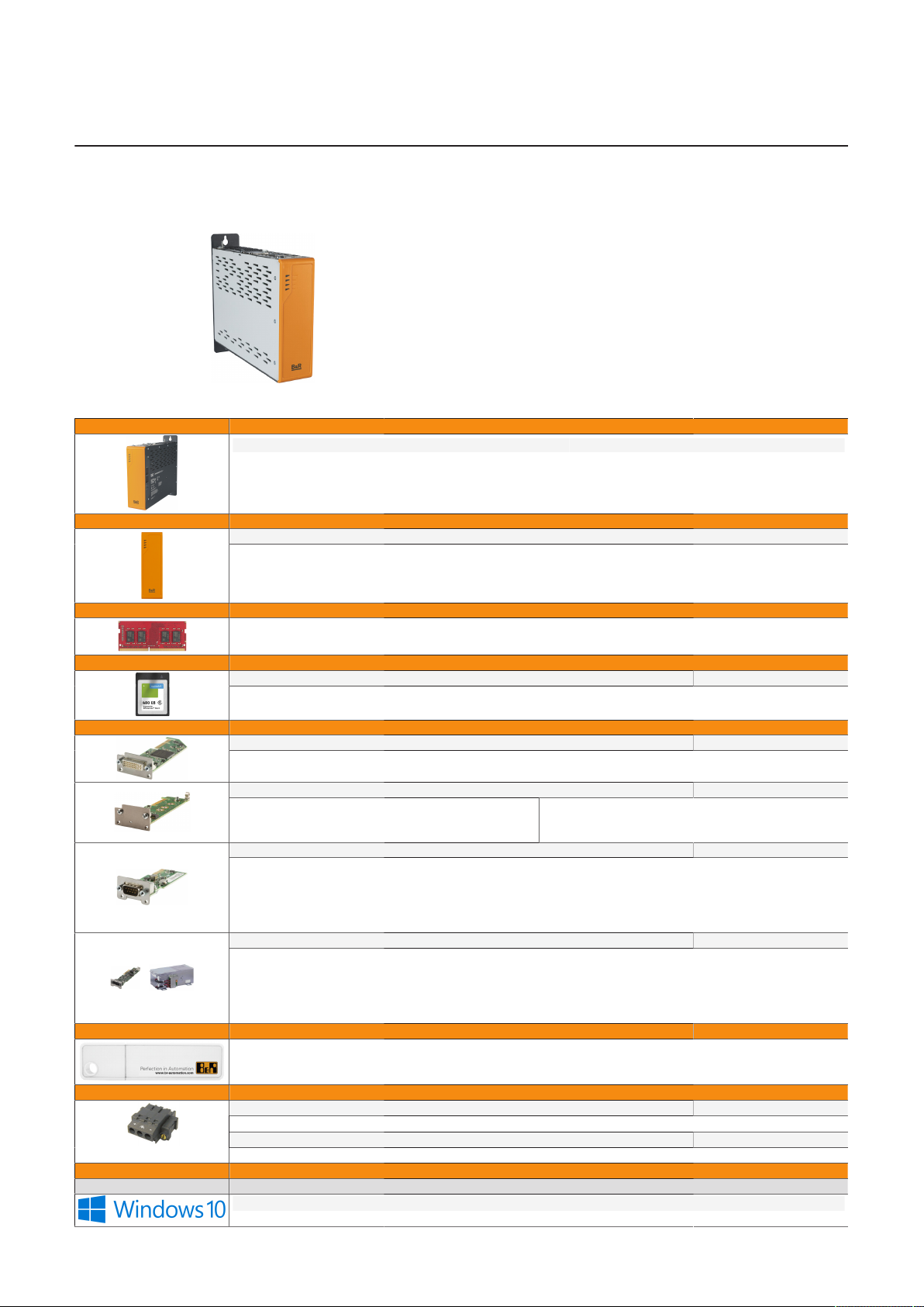
The APC3200 system can be individually configured according to operating conditions and requirements. The following individual components are
mandatory for operation:
•
System unit
•
Main memory
•
Mass storage device for the operating system
(CFexpress or M.2 mass storage)
•
Operating system
System units Select 1.
System unit Processor Processor - Clock frequency Cores
5APC3200.RPL0-000 Intel U300E 1100 MHz 5
5APC3200.RPL1-000 Intel i3-1315URE 1200 MHz 6
5APC3200.RPL2-000 Intel i5-1345URE 1400 MHz 10
5APC3200.RPL3-000 Intel i7-1365URE 1700 MHz 10
Covers Select 1.
Front cover
1)
5ACCFF01.0000-000
5ACCFF01.0000-001
Main memory Select max. 2.
5MMDDR.4096-05 5MMDDR.016G-05
5MMDDR.8192-05 5MMDDR.032G-05
Mass storage devices
Interfaces
USB accessories Optional selection
CFexpress cards Optional, select max. 2
5CFXPR.060G-20 5CFXPR.120G-20 5CFXPR.240G-20 5CFXPR.480G-20 5CFXPR.960G-20
Graphics options
Mass storage options
Interface options Optional, select max. 2
3)
UPS
2)
5ACCLI02.DPO0-000
2)
Adapter card
5ACCMS01.MDT2-000
5AC901.I232-00 5AC901.IPLK-00 5ACCIF02.CANE-000
5AC901.I485-00 5AC901.IRDY-00 5ACCIF02.FPLK-000
5AC901.ICAN-01 5AC901.ISIO-00 5ACCIF02.FPLS-000
5AC901.IETH-00 5AC901.ISRM-00 5ACCIF02.FPSC-000
5AC901.IHDA-00 5ACCIF04.FPLK-000 5ACCIF02.ISS0-000
UPS module + Battery unit + UPS cable
5AC901.IUPS-00 + 5AC901.BUPS-00 5CAUPS.0005-01
5AC901.IUPS-01 + 5AC901.BUPS-01 5CAUPS.0010-01
5ACCLI02.SD40-000
M.2 mass storage devices
5ACCMSM2.0512-000
5ACCMSM2.1024-000
Optional, select max. 1
Optional, select 1 each.
Optional, select 1 each.
5CAUPS.0013-01
5CAUPS.0030-01
MMUSB.032G-02 5MMUSB.4096-02
Terminal blocks
Operating systems Select 1.
GPOS
5SWW10.1668-MUL 5SWW10.1768-MUL 5SWW10.1868-MUL
Power supply connector Select 1.
0TB103.9 0TB103.91
Terminal block for IF option Optional selection
0TB2104.8000
Windows 10
14 Automation PC 3200 User's manual V1.00
Page 15
System overview
Linux for B&R 12
5SWLIN.0968-MUL
RTOS
0TG1000.01 0TG1000.02
1TG4600.10-5 1TG4601.06-5
1TC4700.00 1TG4700.00
1) If no front cover is selected for the device configuration, front cover 5ACCFF01.0000-000 (orange with the B&R logo) is installed and supplied as
standard.
2) Select a graphics option or mass storage option.
3) The UPS module can only be operated in the IF option 1 slot, and the battery unit compatible with the UPS module must be used.
Automation Runtime
B&R Hypervisor
3.1.1 Order number key
Information:
A current order number key is available on the B&R website for easy identification of the
device configuration:
Home > Downloads > Industrial PCs and panels > Automation PC 3200
Automation PC 3200 User's manual V1.00 15
Page 16

System overview
3.2 Overview
Order number Short description Page
0TB103.9 Connector 24 VDC - 3-pin, female - Screw clamp terminal block 3.31 mm² 181
0TB103.91 Connector 24 VDC - 3-pin, female - Cage clamp terminal block 3.31 mm² 181
0AC201.91 Lithium batteries 4 pcs., 3 V / 950 mAh button cell 182
4A0006.00-000 Lithium battery, 3 V / 950 mAh, button cell 182
5CFXPR.060G-20 CFexpress 60 GB TLC 103
5CFXPR.120G-20 CFexpress 120 GB TLC 103
5CFXPR.240G-20 CFexpress 240 GB TLC 103
5CFXPR.480G-20 CFexpress 480 GB TLC 103
5CFXPR.960G-20 CFexpress 960 GB TLC 103
5ACCFF01.0000-000 APC3x00 front cover - Orange - With B&R logo 102
5ACCFF01.0000-001 APC3x00 front cover - Dark gray - Without logo 102
5ACCLI02.DPO0-000 Graphics option - 1x DisplayPort transmitter (version 1.2) - For APC3x00/PPC3x00 - For APC4100 49
5ACCLI02.SD40-000 Graphics option - 1x SDL4 transmitter (max. 1920 x 1080) - For APC3x00/PPC3x00 51
1TC4700.00 License for B&R Hypervisor (TC). One license per target system is required. This license is supported
5AC901.I232-00 Interface card - 1x RS232 interface - For APC910/PPC900 - For APC3x00/PPC3x00 - For APC4100 53
5AC901.I485-00 Interface card - 1x RS232/RS422/RS485 interface - For APC910/PPC900 - For APC3x00/PPC3x00 - For
5AC901.ICAN-01 Interface card - 1x CAN interface (SJA1000) - For APC910/PPC900 - For APC3x00/PPC3x00 - For APC4100 58
5AC901.IETH-00 Interface card - 1x ETH 10/100/1000 - For APC910/PPC900 - For APC3x00/PPC3x00 - For APC4100 61
5AC901.IHDA-00 Interface card - 1x audio interface (1x MIC / 1x Line In / 1x OUT) - For APC910/PPC900 - For APC3x00/
5AC901.IPLK-00 Interface card - 1x POWERLINK interface - 2 MB SRAM - For APC910/PPC900 - For APC3x00/PPC3x00 -
5AC901.IRDY-00 Interface card - Ready relay - For APC910/PPC900 - For APC3x00/PPC3x00 - For APC4100 69
5AC901.ISIO-00 Interface card - System I/O - For APC910/PPC900 - For APC3x00/PPC3x00 - For APC4100 70
5AC901.ISRM-00 Interface card - 2 MB SRAM - For APC910/PPC900 - For APC3x00/PPC3x00 - For APC4100 65
5ACCIF02.CANE-000 Interface card - 1x CAN interface (SJA1000) - 1x ETH 10/100/1000 - For APC3x00/PPC3x00 72
5ACCIF02.FPLK-000 Interface card - 1x POWERLINK interface - 2 MB SRAM - Integrated 2-port hub - Ring redundancy - POW-
5ACCIF02.FPLS-000 Interface card - 2 MB SRAM - 1x RS232 interface - 1x POWERLINK interface - For APC3x00/PPC3x00 78
5ACCIF02.FPSC-000 Interface card - 2 MB SRAM - 1x RS232 interface - 1x CAN interface - 1x POWERLINK interface - 1x X2X -
5ACCIF02.ISS0-000 Interface card - 2x RS232/RS422/RS485 interface - For APC3x00/PPC3x00 85
5ACCIF04.FPLK-000 Interface card - 1x POWERLINK interface - For APC3x00/PPC3x00 - For APC4100 88
5SWLIN.0968-MUL Linux for B&R 12 - 64-bit - Multilingual - APC3200 Kaby Lake (UEFI boot) - CPU U300E - CPU Core
5MMDDR.016G-05 SO-DIMM DDR4, 16384 MB 48
5MMDDR.032G-05 SO-DIMM DDR4, 32768 MB 48
5MMDDR.4096-05 SO-DIMM DDR4, 4096 MB 48
5MMDDR.8192-05 SO-DIMM DDR4, 8192 MB 48
5ACCMS01.MDT2-000 Adapter card for M.2 mass storage - For APC3x00/PPC3x00 - For APC4100 90
5ACCMSM2.0512-000 512 GB M.2 SSD MLC - Innodisk - SATA 92
5ACCMSM2.1024-000 1 TB M.2 SSD MLC - Innodisk - SATA 92
5ACCRHMI.0006-000 HMI installation tool for control cabinet - 1x torque wrench 0.4 - 2.0 Nm - 1x hex head bit 2.5, length 89
1TC4601.06-5 License for Automation Runtime Embedded (TC). One license per target system is required. This license
5APC3200.RPL0-000 APC3200 system unit - Intel U300E 1.1 GHz - 5 core 45
5APC3200.RPL1-000 APC3200 system unit - Intel Core i3 1315URE 1.2 GHz - 6 core 45
5APC3200.RPL2-000 APC3200 system unit - Intel Core i5 1345URE 1.4 GHz - 10 core 45
5APC3200.RPL3-000 APC3200 system unit - Intel Core i7 1365URE 1.7 GHz - 10 core 45
0TG1000.01 Technology Guard (MSD) 159
0TG1000.02 Technology Guard (HID) 159
0TGF016.01 Technology Guard (MSD) with integrated flash drive, 16 GB (MLC) 159
1TG4601.06-5 Automation Runtime Embedded TG license 159
1TG4700.00 B&R Hypervisor 159
Accessories
Batteries
CFexpress cards
Front covers
Graphics options
Hypervisor
159
starting with version 4.9.
Interface options
55
APC4100
63
PPC3x00 - For APC4100
67
For APC4100
76
ERLINK managing or controlled mode - PRC function - For APC3x00/PPC3x00
81
For APC3x00/PPC3x00
Linux for B&R 12
157
i3-1315URE / i5-1345URE / i7-1365URE - Installation - Only available with a new device
Main memory
Mass storage options
Other
180
mm - 1x hex head bit 3.0, length 89 mm - 1x hex head bit 5.0, length 89 mm - 1x Torx 10 bit, length 90 mm
- 1x Torx 20 bit, length 89 mm
Runtime
159
is supported starting with version 4.9.
System units
Technology Guard
16 Automation PC 3200 User's manual V1.00
Page 17

System overview
Order number Short description Page
0TB1210.3100 Connector 300 VDC - 10-pin female - Cage clamp terminal block - Protected against vibration by the
0TB2104.8000 Connector 24 VDC - 4-pin female - Screw clamp terminal block 2.5 mm² 184
5AC901.BUPS-00 Battery unit 4.5 Ah - For UPS 5AC901.IUPS-00 96
5AC901.BUPS-01 Battery unit 2.2 Ah - For UPS 5AC901.IUPS-01 96
5AC901.IUPS-00 UPS - For 4.5 Ah battery 94
5AC901.IUPS-01 UPS - For 2.2 Ah battery 94
5CAUPS.0005-01 UPS cable - 0.5 m - For 5AC901.IUPS-xx 100
5CAUPS.0010-01 UPS cable - 1 m - For 5AC901.IUPS-xx 100
5CAUPS.0013-01 UPS cable - 1.3 m - For 5AC901.IUPS-xx 100
5CAUPS.0030-01 UPS cable - 3 m - For 5AC901.IUPS-xx 100
5SWW10.1668-MUL Windows 10 IoT Enterprise 2021 LTSC - 64-bit - Entry - Multilingual (EN / DE / FR / ES) - APC3200 (UEFI
5SWW10.1768-MUL Windows 10 IoT Enterprise 2021 LTSC - 64-bit - Value - Multilingual (EN / DE / FR / ES) - APC3200 (UEFI
5SWW10.1868-MUL Windows 10 IoT Enterprise 2021 LTSC - 64-bit - High End - Multilingual (EN / DE / FR / ES) - APC3200
Terminal blocks
183
screw flange
Uninterruptible power supply
Windows 10 IoT Enterprise 2021 LTSC
154
boot) - CPU U300E - License - Only available with a new device
154
boot) - CPU Core i3-1315URE / i5-1345URE - License - Only available with a new device
154
(UEFI boot) - CPU Core i7-1365URE - License - Only available with a new device
Automation PC 3200 User's manual V1.00 17
Page 18
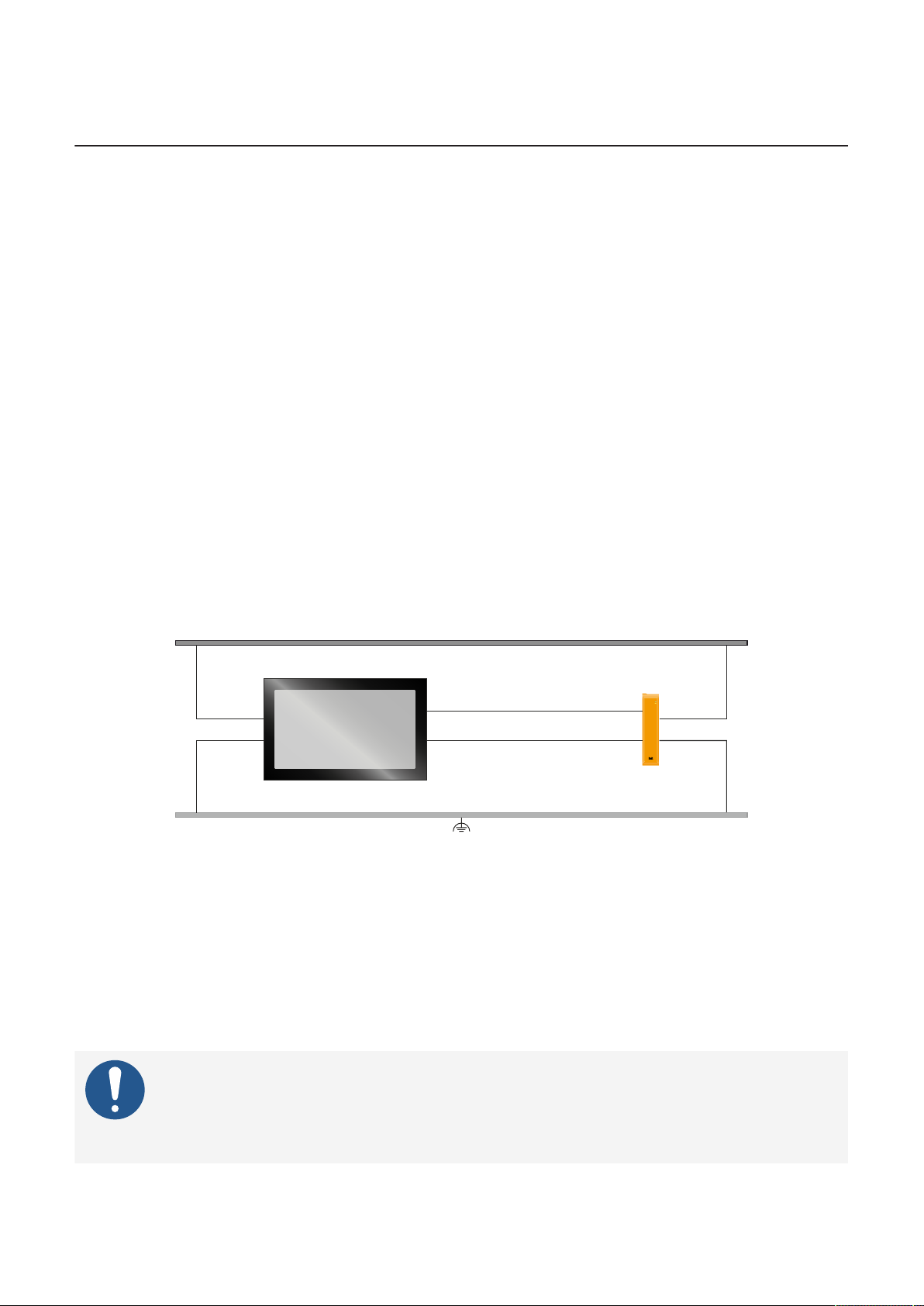
Technical data
Industrial PC
with DP interface(s)
DP cable
Automation Panel
with DP receiver
Power supply (SELV/PELV)
USB cable
4 Technical data
4.1 Complete system
4.1.1 Connection options
An Automation Panel can be connected to the Automation PC via the DisplayPort interfaces and via optional
graphics options:
•
The following chapter describes SDL4 operation. It shows an overview of functions and possible limitations ("SDL4 operation" on page 20).
•
For additional information about DisplayPort, see the corresponding chapter in "Device interfaces and
slots" ("DisplayPort interface" on page 42).
4.1.1.1 DP operation
DisplayPort transfers all communication channels between the B&R industrial PC and monitor/panel via a
DisplayPort cable and a USB cable. This means that widely used standard components can be used.
4.1.1.1.1 DP operation with multi-touch Automation Panel
The display device can be installed up to 7.5 m away from the B&R industrial PC. USB 2.0 is also transferred
over this distance. External adapter modules are not required. A monitor/panel with DP interface or an
Automation Panel with DP receiver can be used as a display device.
The brightness of the display can be adjusted via the on-screen display (OSD).
Availability of the interfaces on the Automation Panel with DP receiver:
DP interface (In)
USB
✓
USB 2.0 (up to 2x) Grounding
✓
24 VDC power supply
✓
✓
Maximum cable length:
•
7.5 m
Requirements
•
Automation Panel with DP receiver
•
Industrial PC with DP interface (onboard or IF option)
•
DP and USB type A/B cable
Information:
B&R cannot guarantee support for third-party products.
The permissibility and suitability of the monitor/panel must be checked individually by
users in accordance with local technical and legal requirements.
18 Automation PC 3200 User's manual V1.00
Page 19

4.1.1.1.2 General limitations/characteristics
•
Key and LED data is not transferred.
•
Data from operating elements is not transferred.
•
Service and diagnostic data is not transferred.
•
The maximum cable length is limited to 7.5 m.
•
Single-touch (analog resistive) is not supported.
Technical data
Automation PC 3200 User's manual V1.00 19
Page 20
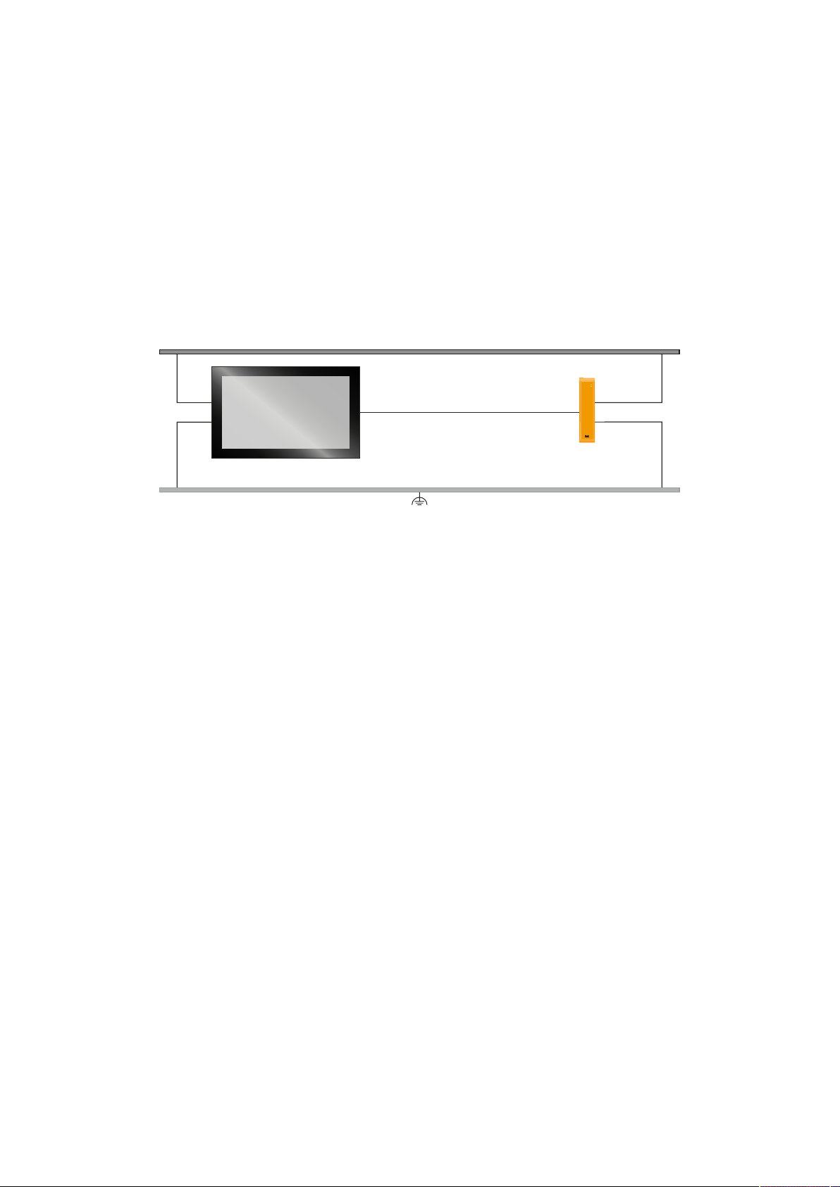
Technical data
SDL4 cable
B&R industrial PC
with SDL4 transmitter
Automation Panel
with SDL4 receiver
Power supply (SELV/PELV)
4.1.1.2 SDL4 operation
Smart Display Link 4 (SDL4) technology transfers all communication channels between a B&R industrial PC
and panel up to 100 m over a standard Ethernet cable (min. Cat 6a). An RJ45 connector is used for the device
connection, which is ideal for confined spaces in feed-throughs and swing arm systems.
4.1.1.2.1 SDL4 operation with SDL4 transmitter
In SDL4 operation with an SDL4 transmitter in the B&R industrial PC, all communication between the Automation Panel and B&R industrial PC takes place via a single SDL4 cable.
In addition to the display data, information from the touch screen, matrix keys, LEDs and service/diagnostic
data is transferred. The Automation Panel can be installed up to 100 m away from the B&R industrial PC.
USB 2.0 is also transferred over this distance and fully integrated into SDL4. External adapter modules are
not required.
The brightness of the display can be set via the ADI, for example.
Availability of the interfaces on the Automation Panel with SDL4 receiver:
SDL4 interface
✓
USB1, USB2✓ USB 2.0 Power supply
✓
Grounding
✓
Maximum cable length for SDL4: 100 m
Requirements
•
Automation Panel with SDL4 receiver
•
B&R industrial PC with SDL4 interface
•
SDL3/SDL4 cable
4.1.1.2.2 General limitations
•
USB 2.0 transfer is limited to 150 Mbit/s with SDL4.
•
A display is always emulated by the SDL4 transmitter using EDID data and hot plug detection, so DVIcompatible operation is possible. For this reason, the following behavior may occur during operation
with multiple displays.
In the operating system, a connected panel is reported by the video driver even in the following situations:
°
No SDL3/SDL4 cable is connected.
°
There is no connection established yet between the SDL4 link module and SDL4 transmitter.
This behavior can be avoided by appropriate configuration in BIOS or via the graphics driver.
20 Automation PC 3200 User's manual V1.00
Page 21
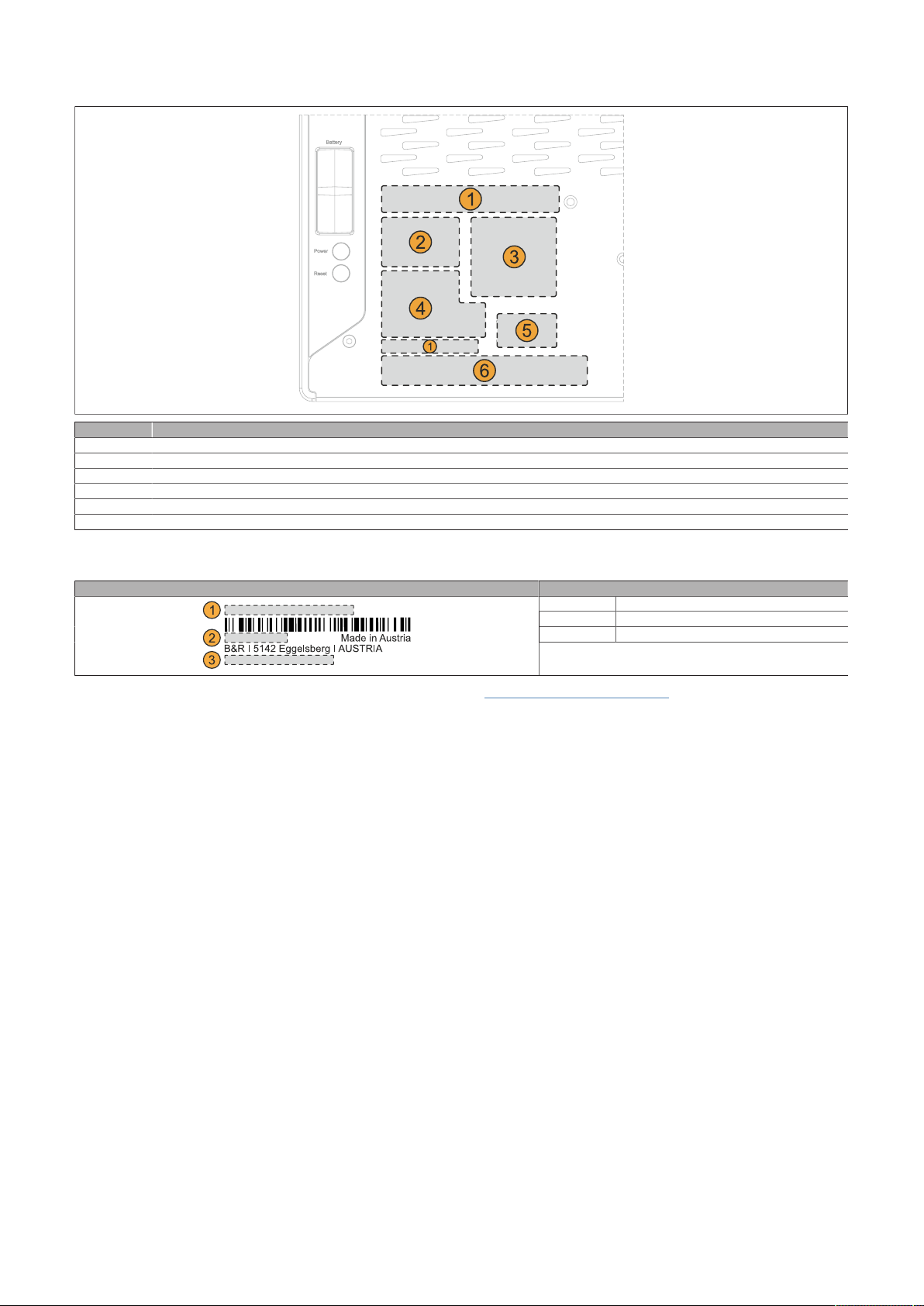
4.1.2 Product information
Position Description
1 Specifications for the device family and electrical properties
2 Device-specific specifications, serial numbers and MAC addresses, see Identification.
3 Valid test and conformity ID for the product, see section "Technical data" on page 46
4 Safety notices, warnings and information about the product
5 License label for operating systems (configuration-dependent)
6 Space for individual customer information (configuration-dependent)
Technical data
4.1.2.1 Identification
Figure (symbolic image) Identification
1 Device number
2 Serial number
3 MAC addresses
-
The device number can be retrieved on the B&R website (www.br-automation.com) using the serial number
of the device (login required). Information (serial number, material number, revision, delivery date and end
of warranty) about all components installed in the system can be retrieved using the device number.
Automation PC 3200 User's manual V1.00 21
Page 22
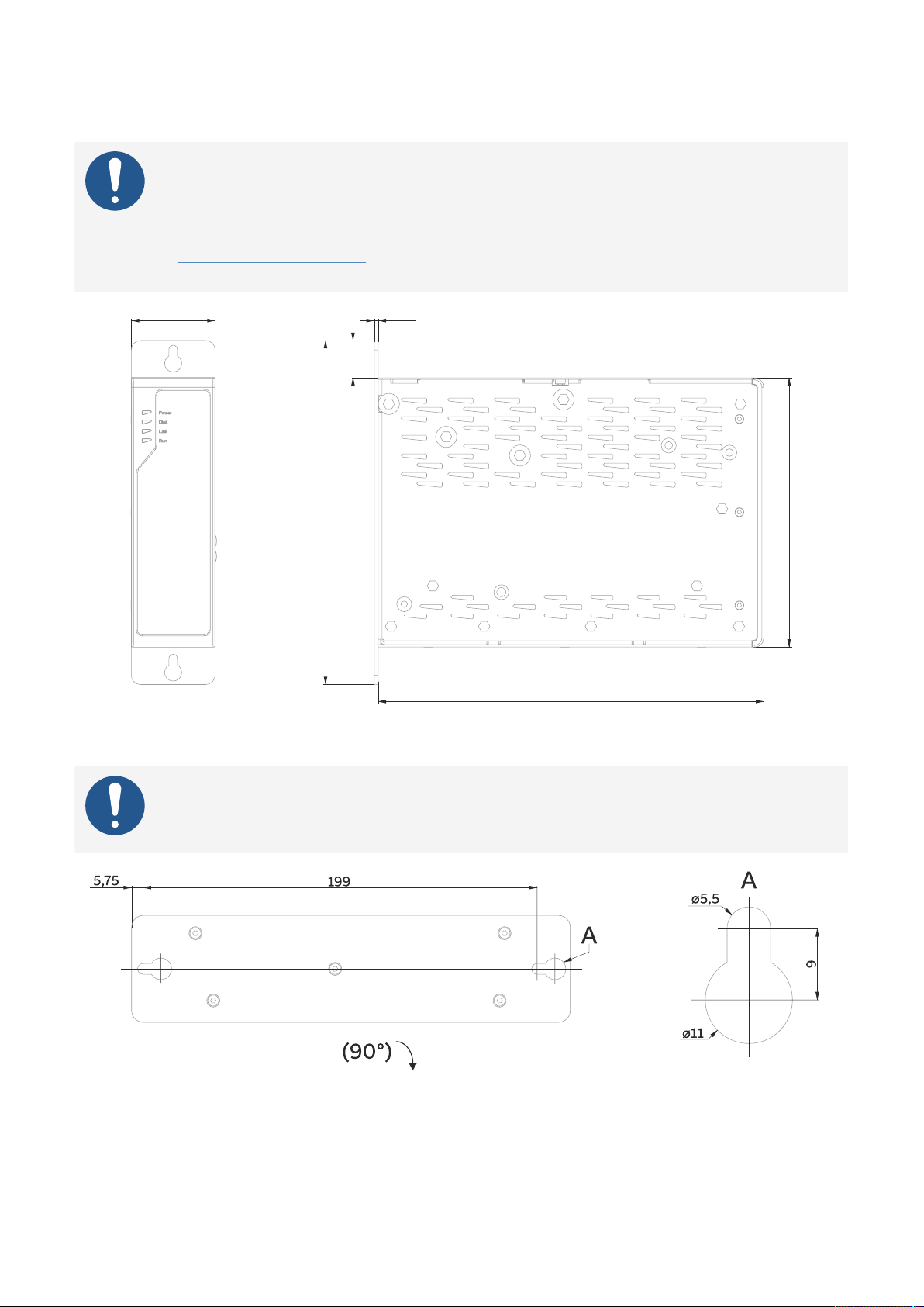
Technical data
54
248.3
221.5
24
2.5
173.5
4.1.3 Mechanical properties
4.1.3.1 Dimensions
Information:
All dimensions, specifications in dimensioned drawings and associated tables are in millimeters [mm].
2D and 3D data (DXF and STEP formats) can be downloaded from the B&R website
(www.br-automation.com). To do this, search for the order number of the device using the
search bar.
4.1.3.1.1 Drilling template
Information:
When installing the device, spacing for air circulation and additional free space for operating and servicing must be taken into account.
22 Automation PC 3200 User's manual V1.00
Page 23
Technical data
S4
S3
S2
S1
1)
2)
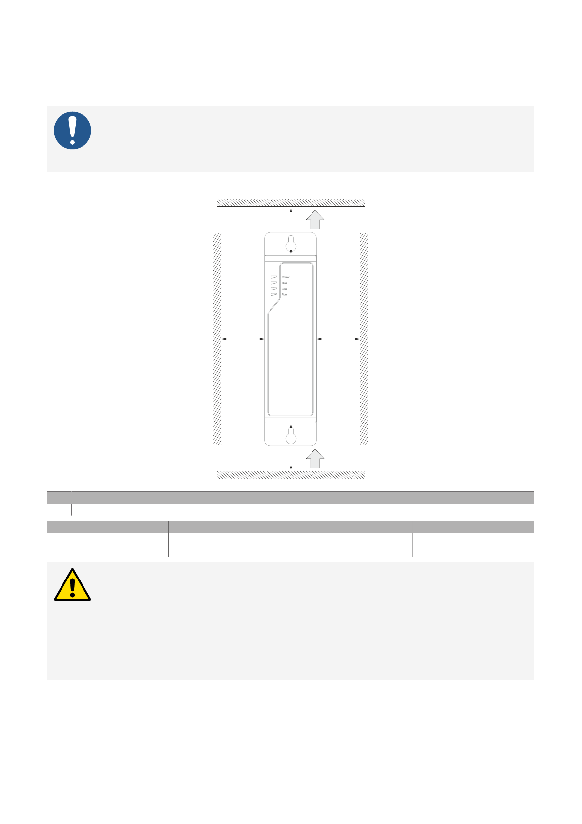
4.1.3.2 Spacing for air circulation
To ensure sufficient air circulation, a specified clearance must be provided above, below, to the side and
behind the device. For the minimum specified clearance, see the following diagrams. This is valid for all
variants.
Information:
The following figure and table exclusively show the thermal view of the complete system.
If additional space is required for operating or servicing the device, this must be taken into
account during installation.
The air inlet and air outlet are shown in the following figure.
Legend
1) Air outlet 2) Air inlet
Name Minimum spacing [mm] Name Minimum spacing [mm]
S1
S3
≥100
≥100
S2
S4
≥50
≥50
Caution!
The specified spacing for air circulation is based on worst-case operation at the maximum
specified ambient temperature. The maximum specified ambient temperature is not permitted to be exceeded!
If the specified spacing for air circulation cannot be maintained, the maximum specified
temperatures of the temperature sensors (see "Temperature sensor positions" on page
31) must be monitored in the application and appropriate measures taken if these val-
ues are exceeded.
Automation PC 3200 User's manual V1.00 23
Page 24
Technical data
4.1.3.3 Mounting orientations
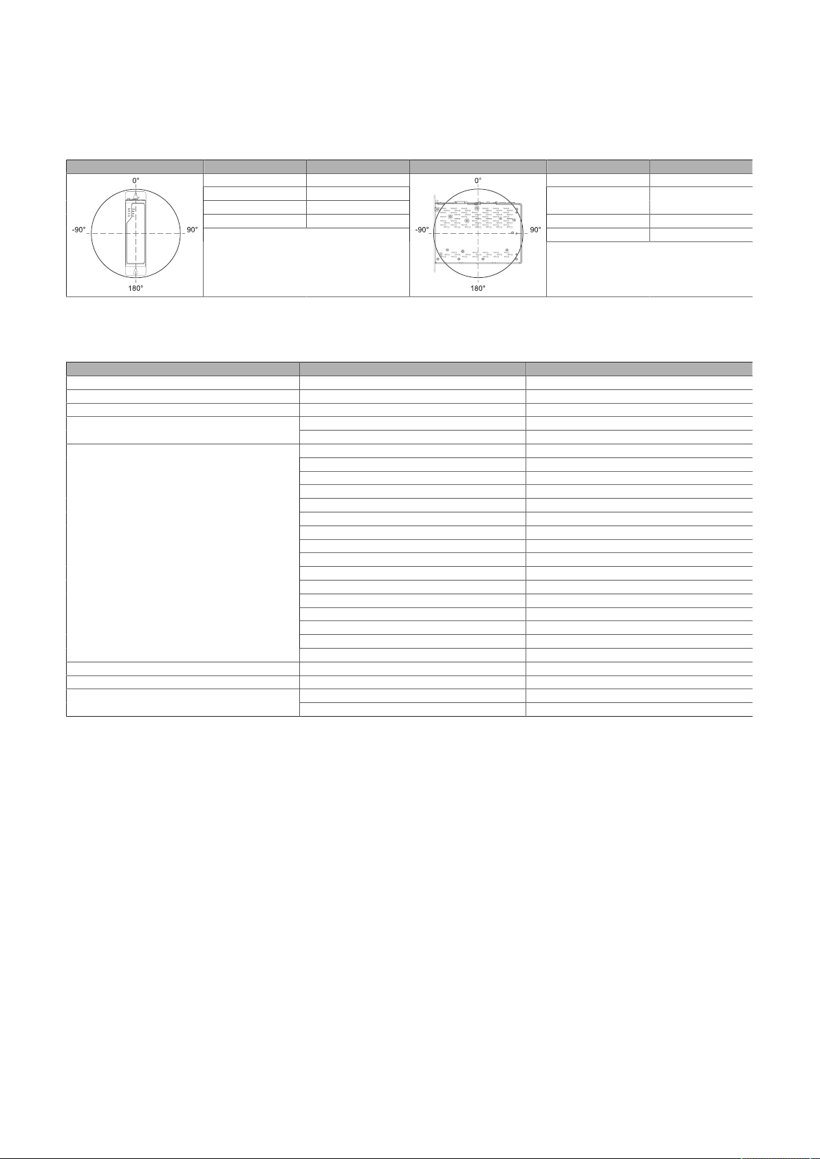
During installation, it is important to make sure that the spacing as described in section "Spacing for air
circulation" on page 23 is observed in order to achieve natural air circulation.
Rear mounting plate
Inclination (°) Derating (°C) Inclination (°) Derating (°C)
0 to ±5 No limitation 0 to ±5 No limitation
+5 to +175 -5
-5 to -175 -10
±175 to ±180 No limitation -5 to -175 -5
5 to 175 Not allowed!
±175 to ±180 No limitation
-
4.1.3.4 Weight specifications
System units and components
Type Order number Weight (g)
System units 5APC3200.RPLx-000 1470
Main memory 5MMDDR.xxxx-0x 10
CFexpress cards 5CFXPR.xxxx-20 10
Graphics options
Interface options
Mass storage options
M.2 mass storage devices 5ACCMSM2.xxxx-000 40
1) Without mass storage device.
1)
5ACCLI02.DPO0-000 27
5ACCLI02.SD40-000 38
5AC901.I232-00 30
5AC901.I485-00 34
5AC901.ICAN-01 33
5AC901.IETH-00 35
5AC901.IHDA-00 21
5AC901.IPLK-00 35
5AC901.IRDY-00 30
5AC901.ISIO-00 30
5AC901.ISRM-00 20
5AC901.IUPS-0x 30
5ACCIF02.CANE-000 60
5ACCIF02.FPLK-000 55
5ACCIF02.FPLS-000 55
5ACCIF02.FPSC-000 55
5ACCIF02.ISS0-000 65
5ACCIF04.FPLK-000 25
5ACCMS01.MDT2-000 35
5ACCFF01.0000-000 30Front covers
5ACCFF01.0000-001 30
1)
-
24 Automation PC 3200 User's manual V1.00
Page 25
Technical data
4.1.4 Environmental properties
4.1.4.1 Temperature specifications
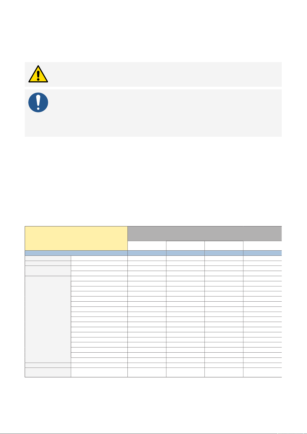
Due to the modularity of this system, the minimum and maximum temperature limit values are specified in
the following tables. Operation outside the specified limit values is not permitted.
Caution!
The actual ambient temperatures in the application can be influenced by many factors.
Information:
The maximum specified ambient temperatures for operation were determined under
worst-case conditions. Experience has shown that higher ambient temperatures can be
achieved with typical applications in Microsoft Windows, for example. A corresponding
test and assessment must be carried out individually for the application (reading out the
temperatures in BIOS or using ADI).
Information about worst-case conditions
•
Thermal Analysis Tool (TAT V02.01.1012) from Intel for simulating 100% processor utilization (thermal
workload)
•
BurnInTest testing tool (BurnIn V10.2 Pro from PassMark Software) for simulating 100% interface load
(Ethernet interfaces, memory)
•
Maximum expansion and power consumption of the system
•
As an alternative to the Thermal Analysis Tool, the Prime95 tool (V3019 Build 20) can be used with the
"Small FFTs" workload and the default settings.
4.1.4.1.1 Minimum ambient temperature for worst-case operation
For the minimum ambient temperature in non-condensing operation, taking into account the CPU used,
see the following table:
All temperature specifications in degrees Celsius
(°C) at 500 m above sea level, non-condensing.
Minimum ambient temperature 0 -25 -25 -25
Main memory 5MMDDR4.xxxx-05
CFexpress cards 5CFXPR.xxxx-20
Graphics options
Interface options
Mass storage options 5ACCMS01.MDT2-000
M.2 mass storage de-
vices
5ACCLI02.DPO0-000
5ACCLI02.SD40-000
5AC901.I232-00
5AC901.I485-00
5AC901.ICAN-01
5AC901.IHDA-00
5AC901.IRDY-00
5AC901.IPLK-00
5AC901.ISIO-00
5AC901.ISRM-00
5AC901.IETH-00
5AC901.IUPS-00
5AC901.IUPS-01
5ACCIF02.CANE-000
5ACCIF02.FPLK-000
5ACCIF02.FPLS-000
5ACCIF02.FPSC-000
5ACCIF02.ISS0-000
5ACCIF04.FPLK-000
5ACCMSM2.xxxx-000
5APC3200.RPL0-000
(U300E 1.1 GHz)
✓ ✓ ✓ ✓
✓ ✓ ✓ ✓
✓
✓
✓ ✓ ✓ ✓
✓ ✓ ✓ ✓
✓ ✓ ✓ ✓
✓
✓
✓
✓
✓
✓ ✓ ✓ ✓
✓
✓
✓ ✓ ✓ ✓
✓
✓
✓
✓ ✓ ✓ ✓
✓
✓ ✓ ✓ ✓
✓ ✓ ✓ ✓
System units (5APC3200.RPLx-000)
5APC3200.RPL1-000
(i3-1315URE 1.2 GHz)
-20 -20 -20
0 0 0
0 0 0
0 0 0
0 0 0
0 0 0
0 0 0
0 0 0
0 0 0
0 0 0
0 0 0
0 0 0
0 0 0
5APC3200.RPL2-000
(i5-1345URE 1.4 GHz)
5APC3200.RPL3-000
(i7-1365URE 1.7 GHz)
Automation PC 3200 User's manual V1.00 25
Page 26
Technical data
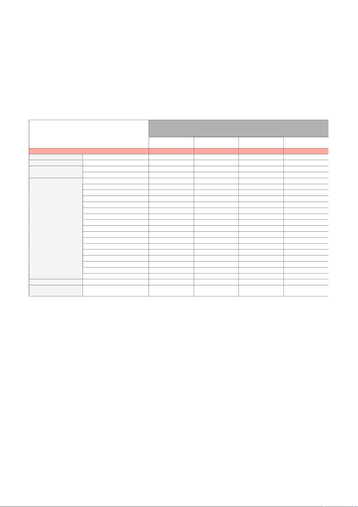
4.1.4.1.2 Maximum ambient temperature for worst-case operation
The following temperature tables show the worst-case values in passive operation under various operating
conditions.
The following limitations and information must be taken into account:
•
All temperature specifications in degrees Celsius [°C] at 500 m above sea level, non-condensing.
•
The respective ambient temperature is typically derated 1°C per 1000 meters starting at 500 m above
sea level.
•
It may be necessary to limit the max. ambient temperature in certain applications (e.g. UL HazLoc) (for
additional information, see "International and national certifications" on page 185).
•
More information about "power and performance profiles" on page 123.
Industrial use condition
5APC3200.RPL0-000
Maximum ambient temperature
Main memory 5MMDDR4.xxxx-05
CFexpress cards 5CFXPR.xxxx-20
Graphics options
Interface options
Mass storage options 5ACCMS01.MDT2-000
M.2 mass storage de-
vices
1) An additional derating of 10°C is required when using 2x 2.5 Gbit/s Ethernet. No derating is necessary with 1x 2.5 Gbit/s Ethernet.
1)
5ACCLI02.DPO0-000
5ACCLI02.SD40-000
5AC901.I232-00
5AC901.I485-00
5AC901.ICAN-01
5AC901.IHDA-00
5AC901.IRDY-00
5AC901.IPLK-00
5AC901.ISIO-00
5AC901.ISRM-00
5AC901.IETH-00
5AC901.IUPS-00
5AC901.IUPS-01
5ACCIF02.CANE-000
5ACCIF02.FPLK-000
5ACCIF02.FPLS-000
5ACCIF02.FPSC-000
5ACCIF02.ISS0-000
5ACCIF04.FPLK-000
5ACCMSM2.xxxx-000 50 45 45 45
(U300E 1.1 GHz)
60 55 50 50
✓ ✓ ✓ ✓
✓ ✓ ✓ ✓
✓ ✓ ✓ ✓
✓ ✓ ✓ ✓
✓ ✓ ✓ ✓
✓ ✓ ✓ ✓
✓ ✓ ✓ ✓
✓ ✓ ✓ ✓
✓ ✓ ✓ ✓
✓ ✓ ✓ ✓
✓ ✓ ✓ ✓
✓ ✓ ✓ ✓
✓ ✓ ✓ ✓
✓ ✓ ✓ ✓
✓ ✓ ✓ ✓
✓ ✓ ✓ ✓
✓ ✓ ✓ ✓
✓ ✓ ✓ ✓
✓ ✓ ✓ ✓
✓ ✓ ✓ ✓
✓ ✓ ✓ ✓
✓ ✓ ✓ ✓
System units (5APC3200.RPLx-000)
5APC3200.RPL1-000
(i3-1315URE 1.2 GHz)
5APC3200.RPL2-000
(i5-1345URE 1.4 GHz)
5APC3200.RPL3-000
(i7-1365URE 1.7 GHz)
26 Automation PC 3200 User's manual V1.00
Page 27
Technical data
Embedded use condition
5APC3200.RPL0-000
Maximum ambient temperature
Main memory 5MMDDR4.xxxx-05
CFexpress cards 5CFXPR.xxxx-20
Graphics options
Interface options
Mass storage options 5ACCMS01.MDT2-000
M.2 mass storage de-
vices
1) An additional derating of 10°C is required when using 2x 2.5 Gbit/s Ethernet. No derating is necessary with 1x 2.5 Gbit/s Ethernet.
1)
5ACCLI02.DPO0-000
5ACCLI02.SD40-000
5AC901.I232-00
5AC901.I485-00
5AC901.ICAN-01
5AC901.IHDA-00
5AC901.IRDY-00
5AC901.IPLK-00
5AC901.ISIO-00
5AC901.ISRM-00
5AC901.IETH-00
5AC901.IUPS-00
5AC901.IUPS-01
5ACCIF02.CANE-000
5ACCIF02.FPLK-000
5ACCIF02.FPLS-000
5ACCIF02.FPSC-000
5ACCIF02.ISS0-000
5ACCIF04.FPLK-000
5ACCMSM2.xxxx-000 45 45 45 45
(U300E 1.1 GHz)
50 50 50 50
✓ ✓ ✓ ✓
✓ ✓ ✓ ✓
✓ ✓ ✓ ✓
✓ ✓ ✓ ✓
✓ ✓ ✓ ✓
✓ ✓ ✓ ✓
✓ ✓ ✓ ✓
✓ ✓ ✓ ✓
✓ ✓ ✓ ✓
✓ ✓ ✓ ✓
✓ ✓ ✓ ✓
✓ ✓ ✓ ✓
✓ ✓ ✓ ✓
✓ ✓ ✓ ✓
✓ ✓ ✓ ✓
✓ ✓ ✓ ✓
✓ ✓ ✓ ✓
✓ ✓ ✓ ✓
✓ ✓ ✓ ✓
✓ ✓ ✓ ✓
✓ ✓ ✓ ✓
✓ ✓ ✓ ✓
System units (5APC3200.RPLx-000)
5APC3200.RPL1-000
(i3-1315URE 1.2 GHz)
5APC3200.RPL2-000
(i5-1345URE 1.4 GHz)
5APC3200.RPL3-000
(i7-1365URE 1.7 GHz)
Automation PC 3200 User's manual V1.00 27
Page 28
Technical data
4.1.4.1.3 Maximum ambient temperature for typical operation
Information and limitations for typical conditions
•
BurnInTest 10.2 from PassMark Software for simulating average system and interface utilization by
means of max. 70% load of all main components (CPU, GPU, RAM, mass storage device, Ethernet)
•
No permanent 100% processor utilization and graphics utilization
•
2x 2.5 Gigabit Ethernet
•
Power consumption of the complete system is limited to 50 W (including 20 W USB power).
For information about the power consumption of individual components, see "Power calculation" on
page 34.
•
All temperature specifications in degrees Celsius [°C] at 500 m above sea level, non-condensing.
•
The respective ambient temperature is typically derated 1°C per 1000 meters starting at 500 m above
sea level.
•
More information about "power and performance profiles" on page 123.
Industrial use condition
5APC3200.RPL0-000
Maximum ambient temperature
Main memory 5MMDDR4.xxxx-05
CFexpress cards 5CFXPR.xxxx-20
Graphics options
Interface options
Mass storage options 5ACCMS01.MDT2-000
M.2 mass storage de-
vices
1) An additional derating of 10°C is required when using 2x 2.5 Gbit/s Ethernet. No derating is necessary with 1x 2.5 Gbit/s Ethernet.
1)
5ACCLI02.DPO0-000
5ACCLI02.SD40-000
5AC901.I232-00
5AC901.I485-00 55 55
5AC901.ICAN-01
5AC901.IHDA-00 55 55
5AC901.IRDY-00
5AC901.IPLK-00 55 55
5AC901.ISIO-00
5AC901.ISRM-00 55 55
5AC901.IETH-00
5AC901.IUPS-00
5AC901.IUPS-01
5ACCIF02.CANE-000 55 55
5ACCIF02.FPLK-000 55 55
5ACCIF02.FPLS-000 55 55
5ACCIF02.FPSC-000 55 55
5ACCIF02.ISS0-000
5ACCIF04.FPLK-000 55 55
5ACCMSM2.xxxx-000 55 55
(U300E 1.1 GHz)
60 60 55 55
✓ ✓ ✓ ✓
✓ ✓ ✓ ✓
✓ ✓ ✓ ✓
✓ ✓ ✓ ✓
✓ ✓ ✓ ✓
✓ ✓ ✓ ✓
✓ ✓ ✓ ✓
✓ ✓ ✓ ✓
✓ ✓ ✓ ✓
✓ ✓ ✓ ✓
✓ ✓ ✓ ✓
✓ ✓ ✓ ✓
✓ ✓ ✓ ✓
System units (5APC3200.RPLx-000)
5APC3200.RPL1-000
(i3-1315URE 1.2 GHz)
5APC3200.RPL2-000
(i5-1345URE 1.4 GHz)
5APC3200.RPL3-000
(i7-1365URE 1.7 GHz)
✓ ✓
✓ ✓
✓ ✓
✓ ✓
✓ ✓
✓ ✓
✓ ✓
✓ ✓
✓ ✓
✓ ✓
28 Automation PC 3200 User's manual V1.00
Page 29

Technical data
4.1.4.1.4 Determining the ambient temperature
1. Select the system unit.
2. The columns specify the maximum or minimum temperature in worst-case operation of the complete
system depending on the respective system unit.
Information:
The maximum and typical temperature specifications correspond to a specification
at 500 meters above sea level. The respective ambient temperature is derated approx. 1°C per 1000 meters starting at 500 m above sea level.
3. If expansion options and CFexpress cards are additionally installed in the APC3200 system, they may
result in a temperature limitation.
°
If a
lems.
°
If the installed component has a temperature specification (e.g. "45[°C]"), the ambient temperature of the complete system is not permitted to exceed this value.
4. Possible limitations may arise due to the mounting orientation . For additional information, see section "Mounting orientations" on page 24.
5. The relevant test and assessment must be carried out individually for the application (reading out the
temperatures in BIOS or using ADI).
(check mark) is entered for the installed component, it can be operated without any prob-
"✓"
4.1.4.1.5 Temperature monitoring
Sensors monitor temperature values at various areas in the APC3200. For the position of temperature sensors, see section "Temperature sensor positions" on page 31. The values specified there represent the
defined maximum temperature at this measuring point. If the temperature is exceeded, no alarm is triggered.
Temperatures1) can be read out in different ways in approved operating systems:
•
BIOS (see "Mainboard" on page 125)
•
ADI
•
HMI Service Center
•
Automation Runtime library
The CFexpress cards available from B&R are equipped with S.M.A.R.T support2). Various parameters (e.g.
temperature) can be read out in approved Microsoft Windows or Linux for B&R operating systems.
1)
The measured temperature is a guide value for the immediate ambient temperature, but it may have been influenced by neighboring components.
2)
Self Monitoring, Analysis and Reporting Technology
Automation PC 3200 User's manual V1.00 29
Page 30

Technical data
4.1.4.1.6 Ambient temperature for storage and transport
The following table provides an overview of the minimum and maximum ambient temperatures for storing
and transporting the complete system. Limitations are possible due to individual components.
System units and components
Type Order number Storage (°C) Transport (°C)
System unit 5APC3200.RPLx-000 -20 to 60 -20 to 60
Main memory 5MMDDR.xxxx-05 -20 to 60 -20 to 60
CFexpress card 5CFXPR.xxxx-20 -40 to 85 -40 to 85
Graphics option
Interface option
Mass storage option 5ACCMS01.MDT2-000 -20 to 60 -20 to 60
M.2 mass storage devices 5ACCMSM2.xxxx-000 -55 to 95 -55 to 95
5ACCLI02.DPO0-000 -20 to 60 -20 to 60
5ACCLI02.SD40-000 -20 to 60 -20 to 60
5AC901.I232-00 -20 to 60 -20 to 60
5AC901.I485-00 -20 to 60 -20 to 60
5AC901.ICAN-01 -20 to 60 -20 to 60
5AC901.IETH-00 -20 to 60 -20 to 60
5AC901.IHDA-00 -20 to 60 -20 to 60
5AC901.IPLK-00 -20 to 60 -20 to 60
5AC901.IRDY-00 -20 to 60 -20 to 60
5AC901.ISIO-00 -20 to 60 -20 to 60
5AC901.ISRM-00 -20 to 60 -20 to 60
5AC901.IUPS-00 -20 to 60 -20 to 60
5AC901.IUPS-01 -20 to 60 -20 to 60
5ACCIF02.CANE-000 -20 to 60 -20 to 60
5ACCIF02.FPLK-000 -20 to 60 -20 to 60
5ACCIF02.FPLS-000 -20 to 60 -20 to 60
5ACCIF02.FPSC-000 -20 to 60 -20 to 60
5ACCIF02.ISS0-000 -20 to 60 -20 to 60
5ACCIF04.FPLK-000 -20 to 60 -20 to 60
30 Automation PC 3200 User's manual V1.00
Page 31
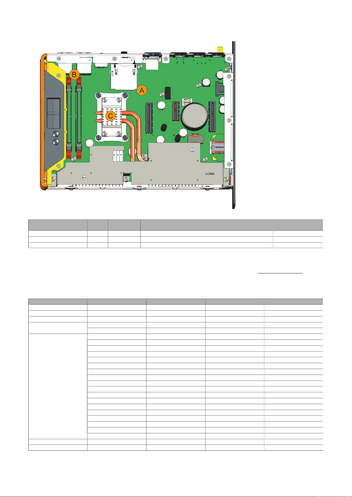
4.1.4.1.7 Temperature sensor positions
Technical data
ADI sensors Position Measuring
point for
System unit sensor 1 A CFexpress2 Temperature of the CFexpress environment 90
System unit sensor 2 B ETH Temperature of the Ethernet environment 90
System unit sensor 3 C CPU Temperature of the processor 95
Measurement Max. specified (°C)
4.1.4.2 Relative humidity
The following tables show the minimum and maximum relative humidity (at 30°C, non-condensing) of the
individual components that are relevant for limiting the relative humidity of the complete system. The smallest or largest value must always be used for this determination. For more detailed information, see technical data or temperature/humidity diagrams of the individual components.
Component Order number Operation [%] Storage [%] Transport [%]
System units 5APC3200.RPLx-000 5 to 90 5 to 95 5 to 95
Main memory 5MMDDR.xxxx-05 10 to 90 5 to 95 5 to 95
CFexpress cards 5CFXPR.xxxx-20 Max. 85% at 85°C Max. 85% at 85°C Max. 85% at 85°C
Graphics options
Interface options
Mass storage options
M.2 mass storage devices 5ACCMSM2.xxxx-000 5 to 90 5 to 95 5 to 95
1) These values can be limited by the mass storage device used.
5ACCLI02.DPO0-000 5 to 90 5 to 95 5 to 95
5ACCLI02.SD40-000 5 to 90 5 to 95 5 to 95
5AC901.I232-00 5 to 90 5 to 95 5 to 95
5AC901.I485-00 5 to 90 5 to 95 5 to 95
5AC901.ICAN-00 5 to 90 5 to 95 5 to 95
5AC901.ICAN-01 5 to 90 5 to 95 5 to 95
5AC901.IHDA-00 5 to 90 5 to 95 5 to 95
5AC901.IRDY-00 5 to 90 5 to 95 5 to 95
5AC901.IPLK-00 5 to 90 5 to 95 5 to 95
5AC901.ISIO-00 5 to 90 5 to 95 5 to 95
5AC901.ISRM-00 5 to 90 5 to 95 5 to 95
5AC901.IETH-00 5 to 90 5 to 95 5 to 95
5AC901.IUPS-00 5 to 90 5 to 95 5 to 95
5AC901.IUPS-01 5 to 90 5 to 95 5 to 95
5ACCIF02.CANE-000 5 to 90 5 to 95 5 to 95
5ACCIF02.FPLK-000 5 to 90 5 to 95 5 to 95
5ACCIF02.FPLS-000 5 to 90 5 to 95 5 to 95
5ACCIF02.FPSC-000 5 to 90 5 to 95 5 to 95
5ACCIF02.ISS0-000 5 to 90 5 to 95 5 to 95
5ACCIF04.FPLK-000 5 to 90 5 to 95 5 to 95
1)
5ACCMS01.MDT2-000 5 to 90 5 to 95 5 to 95
Automation PC 3200 User's manual V1.00 31
Page 32

Technical data
4.1.4.3 Vibration and shock
The following table provides an overview of the maximum vibrations and shock values of the complete
system. Limitations are possible due to individual components.
Vibration
Automation PC Operation
Continuous Periodic
2 to 9 Hz:
1.75 mm amplitude
9 to 200 Hz: 0.5 g
Automation PC Operation
15 g, 11 ms 30 g, 6 ms 30 g, 6 ms
1) Testing is performed per EN 60068-2-6.
2) Testing is performed per EN 60068-2-27.
3) The specification refers to a device in its original packaging.
1)
3.5 mm amplitude
2)
2 to 9 Hz:
9 to 200 Hz: 1 g
Shock
2 to 8 Hz: 7.5 mm amplitude
8 to 200 Hz: 2 g
200 to 500 Hz: 4 g
Storage
Storage
1)3)
2)3)
Transport
2 to 8 Hz: 7.5 mm amplitude
8 to 200 Hz: 2 g
200 to 500 Hz: 4 g
Transport
1)3)
2)3)
4.1.4.4 Degree of protection
Under the following conditions, the Automation PC 3200 offers IP20 protection per EN 60529:
•
Correct installation of the Automation PC 3200 (see "Installation and wiring" on page 104)
•
Installation of all covers or components on interfaces and slots
•
Compliance with all ambient conditions
32 Automation PC 3200 User's manual V1.00
Page 33
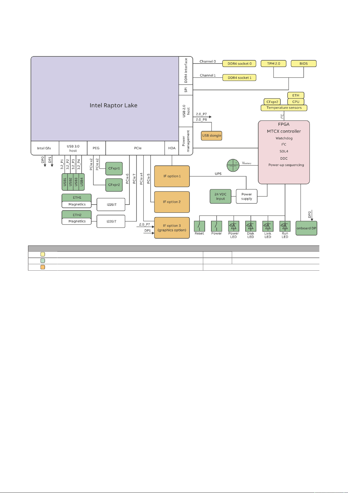
4.1.5 Electrical properties
4.1.5.1 Block diagram
Technical data
Legend
Internal interface
External interface
Internal interface, removable/configurable -
2.0_Px USB 2.0 port x
3.2_Px USB 3.2 port x
Automation PC 3200 User's manual V1.00 33
Page 34
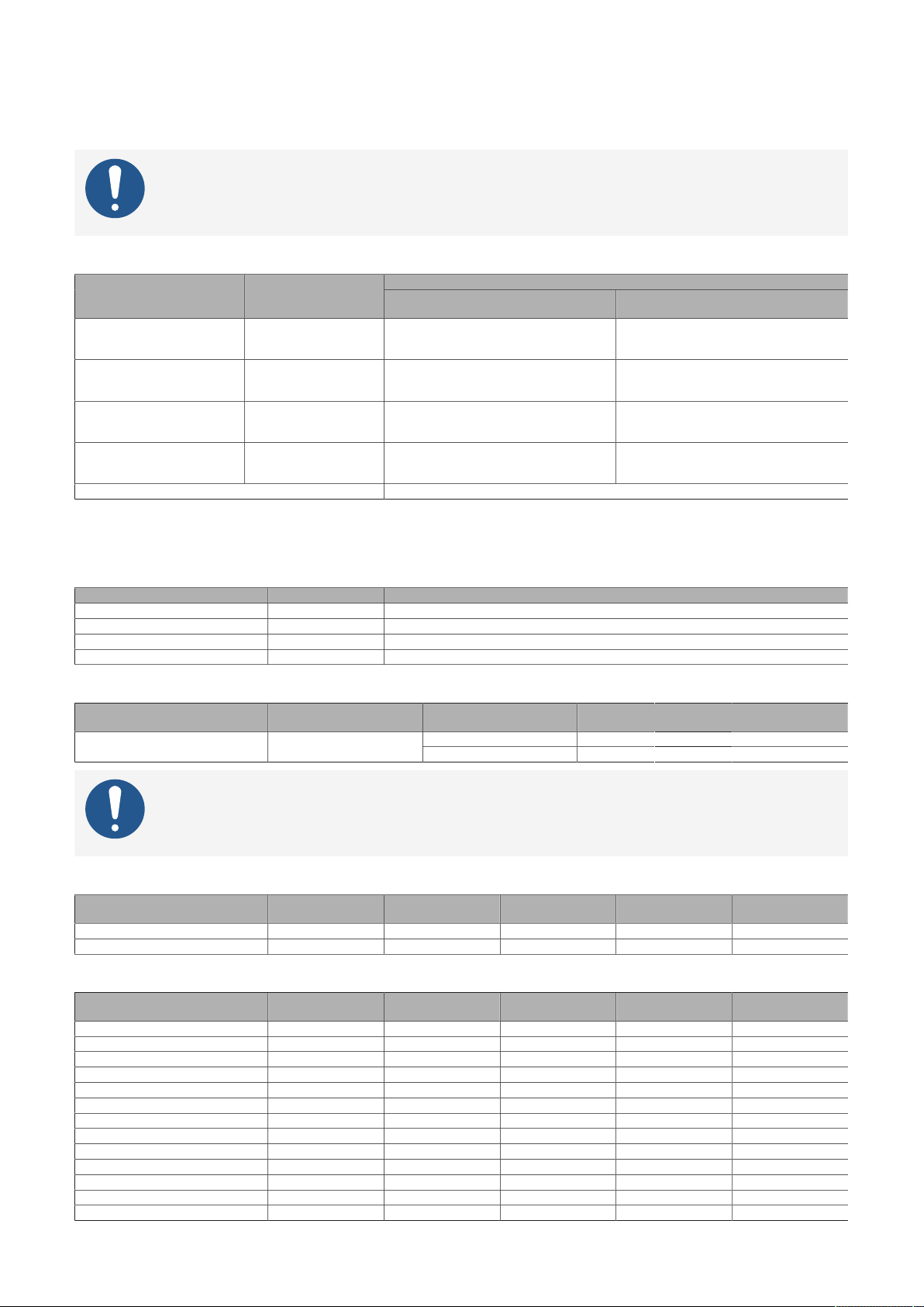
Technical data
4.1.5.2 Power calculation
In order to calculate the total power of the Automation PC 3200, the power ratings of the system unit used
all other installed components must be added together.
Information:
Unless otherwise specified, the following values are maximum values and additional consumers (e.g. USB devices) are not taken into account.
System units
Type Order number
APC3200 C-3965U 2C 2.2 GHz 5APC3200.RPL0-000 Continuous max. 20 W
APC3200 i3-7100U 2C 2.4 GHz 5APC3200.RPL1-000 Continuous max. 23 W
APC3200 i5-7300U 2C 2.6 GHz 5APC3200.RPL2-000 Continuous max. 27 W
APC3200 i7-7600U 2C 2.8 GHz 5APC3200.RPL3-000
USB peripherals Additional max. 20 W (4x max. 5 W)
1) The specified values refer to BIOS settings with approx. 27 W continuous power.
"CPU turbo power limit (PL2)", which can be present for a short time (approx. 10 s) when turbo is enabled, must also be taken into account (to be
configured in the BIOS).
Continuous max. 27 W
For max. 10 s (CPU Pow-
er Limit 2) max. 30 W
Total power consumption of the system unit
Industrial use
Maximum system performance
For max. 10 s (CPU Power Limit 2) max. 75 W
Continuous max. 27 W
For max. 10 s (CPU Pow-
er Limit 2) max. 50 W
Continuous max. 27 W
For max. 10 s (CPU Pow-
er Limit 2) max. 55 W
Continuous max. 27 W
For max. 10 s (CPU Pow-
er Limit 2) max. 70 W
Continuous max. 27 W
1)
Balanced mode /
Main memory
Type Order number Total power consumption
4 GB RAM 5MMDDR.4096-05 2.5 W
8 GB RAM 5MMDDR.8192-05 3.0 W
16 GB RAM 5MMDDR.016G-05 3.5 W
32 GB RAM 5MMDDR.032G-05 4.0 W
M.2 mass storage option
Type Order number
(adapter card)
Order number (M.2 SSD) Total power consumption
5ACCMSM2.0512-000 5.0 WM.2 mass storage option 5ACCMS01.MDT2-000
5ACCMSM2.1024-000 5.0 W
Information:
This information applies exclusively to the M.2 mass storage devices available from B&R.
If third-party mass storage devices are used, refer to the manufacturer's documentation.
Graphics options
Type Order number +5 V +3.3 V +12 V Total
DisplayPort transmitter 5ACCLI02.DPO0-000 2.7 W 0.3 W - 3 W
SDL4 transmitter 5ACCLI02.SD40-000 2.5 W 2 W - 4.5 W
Interface options
Type Order number +5 V +3.3 V +12 V Total
RS232 IF option 5AC901.I232-00 1 W - - 1 W
RS232/RS422/RS485 IF option 5AC901.I485-00 1 W - - 1 W
CAN IF option 5AC901.ICAN-01 0.5 W - - 0.5 W
Audio IF option 5AC901.IHDA-00 0.2 W 0.2 W - 0.4 W
Ready relay IF option 5AC901.IRDY-00 0.2 W - - 0.2 W
POWERLINK IF option 5AC901.IPLK-00 - 1.5 W - 1.5 W
System I/O IF option 5AC901.ISIO-00 - 0.5 W - 0.5 W
SRAM IF option 5AC901.ISRM-00 - 2 W - 2 W
Gigabit Ethernet IF option 5AC901.IETH-00 - 1 W - 1 W
UPS - For 4.5 Ah battery (standby) 5AC901.IUPS-00 - - 0.1 W 0.1 W
UPS - For 2.2 Ah battery (standby) 5AC901.IUPS-01 - - 0.1 W 0.1 W
Ethernet + CAN IF option 5ACCIF02.CANE-000 0.5 W 1 W - 1.5 W
2x POWERLINK IF option 5ACCIF02.FPLK-000 - 2 W - 2 W
power consumption
power consumption
34 Automation PC 3200 User's manual V1.00
Page 35

Technical data
Type Order number +5 V +3.3 V +12 V Total
SRAM POWERLINK RS232 IF option 5ACCIF02.FPLS-000 - 1.75 W - 1.75 W
SRAM POWERLINK CAN X2X RS232
IF option
2x RS232/RS422/RS485 IF option 5ACCIF02.ISS0-000 1.5 W - - 1.5 W
POWERLINK IF option 5ACCIF04.FPLK-000 - 1.5 W - 1.5 W
5ACCIF02.FPSC-000
0.6 W 1.4 W - 2 W
power consumption
CFexpress cards
Type Order number Total power consumption
CFexpress card 5CFXPR.xxxx-20 Max. 3 W
4.1.5.2.1 Calculation example
System unit 5APC3200.RPL3-000
(system performance mode)
75 W
(with 10 W USB consumer)
85 W
Main memory module 5MMDDR.016G-05 3.5 W 3.5 W
Interface option 5AC901.ISRM-00 2 W 2 W
M.2 mass storage option 5ACCMSM0.MDT2-000
1)
5 W 5 W
1x CFexpress card 5CFXPR.xxxx-20 3 W 3 W
Total max.: 98.5 W
1) With M.2 SSD 5ACCMSM2.xxxx-000.
Automation PC 3200 User's manual V1.00 35
Page 36
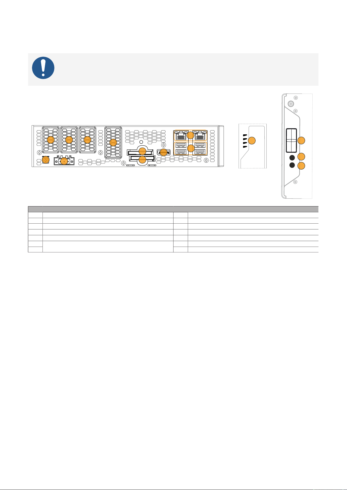
Technical data
11
1
2
3
4
6
5
7
8
9
10
13
14
4a
12
4.1.6 Device interfaces and slots
4.1.6.1 Device interface overview
Information:
The available interfaces are numbered for easy differentiation. The numbering used by the
operating system may differ.
1 "Grounding" on page 37 8 "DisplayPort interface" on page 42
2 "IF option 1 slot" on page 42 9 "Ethernet interfaces" on page 38
3 "+24 VDC power supply" on page 37 10 "USB interfaces" on page 38
4 + 4a "IF option 2 slot" on page 42 11 "LED status indicators" on page 41
5 "IF option 3 slot" on page 42 12 Reset - "Power and reset buttons" on page 43
6 13 Power - "Power and reset buttons" on page 43
"CFexpress slots" on page 39
7
Legend
14 "Battery" on page 40
36 Automation PC 3200 User's manual V1.00
Page 37
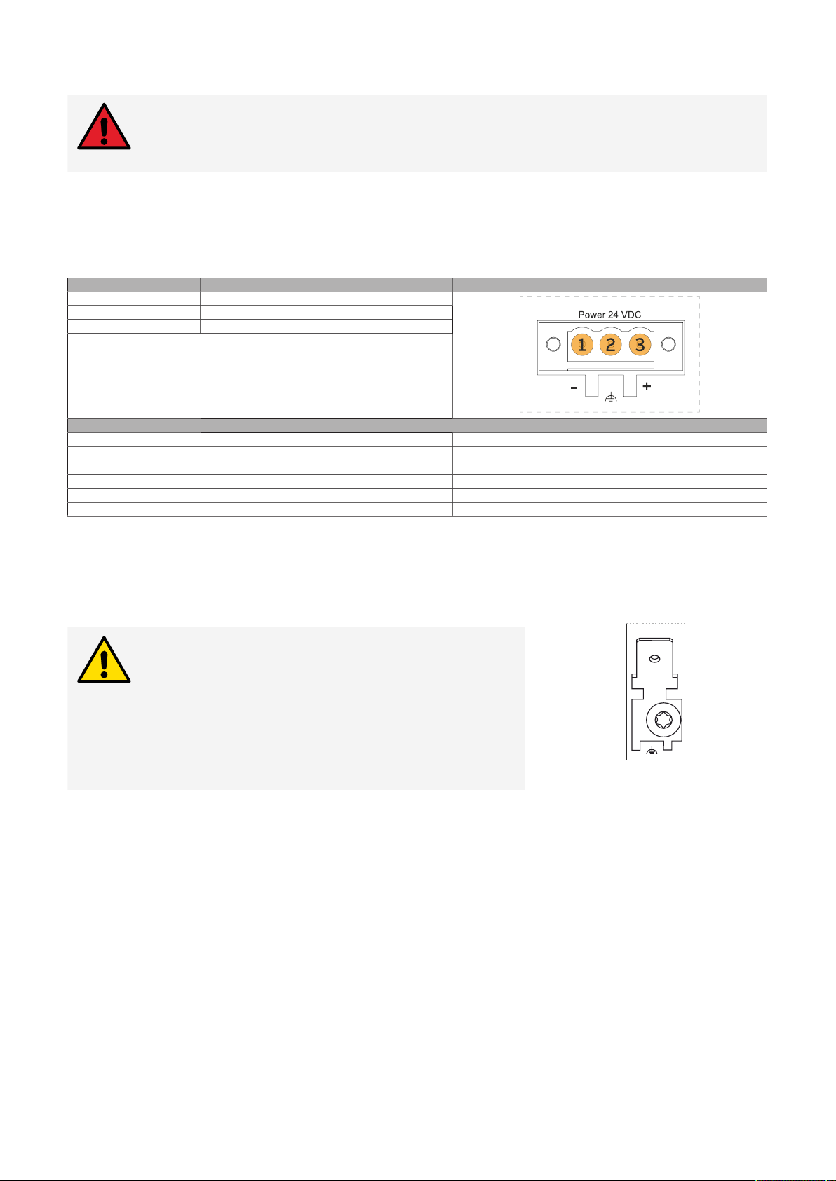
Technical data
4.1.6.2 +24 VDC power supply
Danger!
This device is only permitted to be supplied with a SELV/PELV power supply unit or with
safety extra-low voltage (SELV) per IEC 61010-2-201.
The necessary 3-pin connector is not included in delivery; for suitable accessories, see "0TB103.9x" on page
181.
The device is protected against overload and reverse polarity by a soldered fuse (15 A, fast-acting). If the
fuse is defective (e.g. due to overload), the device must be sent to B&R for repairs. If the polarity is reversed,
it is not necessary to replace the fuse.
Pin Description Figure
1 2 Functional ground
3 +
•
Reverse polarity protection
•
3-pin
•
Male
Electrical properties
Nominal voltage 24 VDC, SELV/PELV
Nominal current Max. 5.5 A
Operating voltage 24 VDC ±25%
Overvoltage category per EN 61131-2 II
Inrush current Max. 80 A for < 300 µs
Galvanic isolation Yes
1) IEC 61010-2-201 requirements must be observed.
2) Maximum possible current consumption at 24 V with 132 W. This may vary depending on the configuration. The inrush current must also be taken
into account when selecting the power supply unit.
3) Uin = 24 VDC
1)
2)
3)
4.1.6.2.1 Grounding
Caution!
The functional ground (power supply pin 2 and ground
connection) must be connected to the central grounding point (e.g. control cabinet or system) via the shortest possible path with the lowest possible resistance
and with the largest possible wire cross section. This
type of grounding is mandatory for proper functionality.
For example, a copper strip must be attached to the ground connection at a central grounding point of
the control cabinet or system in which the device is installed. The line cross section should be as large as
possible (at least 2.5 mm²).
Automation PC 3200 User's manual V1.00 37
Page 38
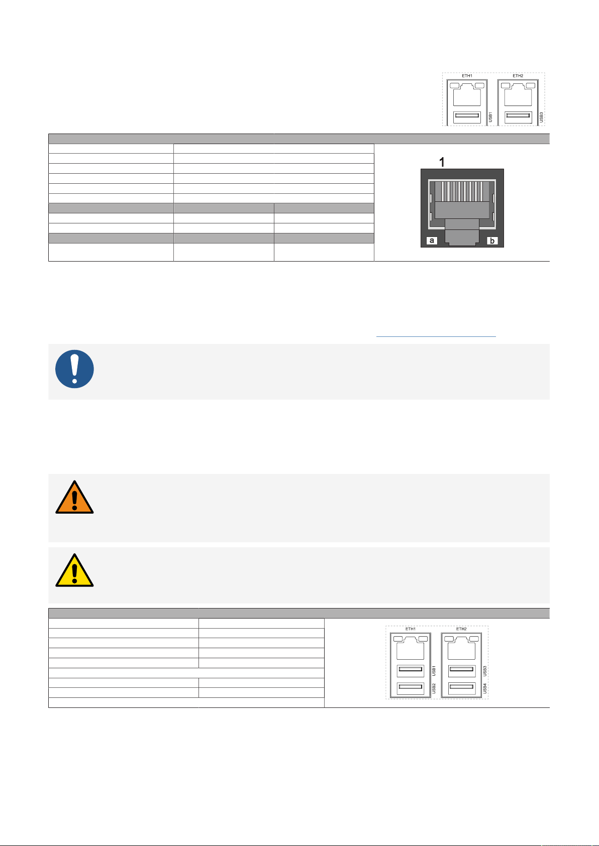
Technical data
4.1.6.3 Ethernet interfaces
The Ethernet controllers are routed externally via the
system unit.
Variant RJ45, female
Controller Intel I226-IT
Wiring S/STP (Cat 5e)
Transfer rate 10/100/1000/2500 Mbit/s
TSN support Yes
Cable length Max. 100 m (min. Cat 5e)
LED "Speed" (a) On Off
Green 2500 Mbit/s 100/10 Mbit/s
Orange (dark) 1000 Mbit/s -
LED "Link" (b) On Active
Orange (light) Link (a connection to an
Ethernet network exists)
1) Switching takes place automatically.
2) The transfer rate / connection is only available if LED "Link" is active at the same time.
ETH1, ETH2
1)
2)
Blinking (data be-
ing transferred)
Driver support
A special driver is required to operate the Ethernet controller. Drivers for approved operating systems are
available for download in the Downloads section of the B&R website (www.br-automation.com).
Information:
Necessary drivers must be downloaded from the B&R website, not from manufacturer websites.
4.1.6.4 USB interfaces
The APC3200 is equipped with a Universal Serial Bus (USB) 3.2 host controller with several USB ports. Four
USB 3.2 interfaces are routed to the outside and are freely available. An additional USB 2.0 interface located
inside the device.
Warning!
USB peripheral devices can be connected to the USB interfaces. Due to the variety of USB
devices available on the market, B&R cannot guarantee their functionality. The functionality of USB devices available from B&R is ensured.
Caution!
Due to the general PC specification, this interface must be handled with the utmost care
with regard to EMC, cable routing, etc.
Standard USB 3.2 Gen2
Variant Type A, female
Quantity 4
Transfer rate Up to SuperSpeed+ (10 Gbit/s)
Current-carrying capacity
Cable length
1) Each USB interface is protected by a maintenance-free "USB current-limiting switch" (max. 1 A).
1)
USB 2.0 Max. 5 m (without hub)
USB 3.2 Max. 3 m (without hub)
-
Max. 1 A per connection
USB1-4
A USB 2.0 interface is available internally for the Technology Guard. The system unit must be opened for
replacement or retrofitting.
38 Automation PC 3200 User's manual V1.00
Page 39
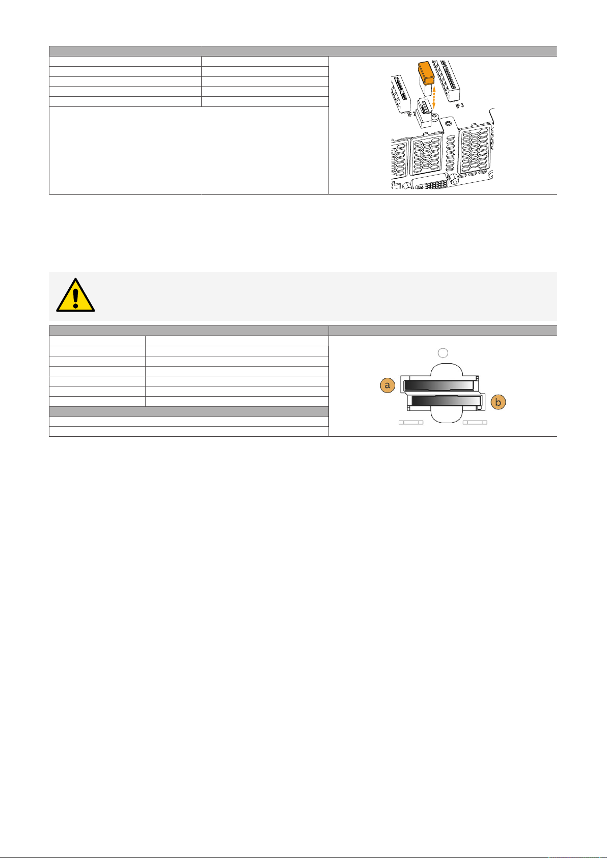
Technical data
Standard USB 2.0
Variant Type A, female
Transfer rate Up to high speed (480 Mbit/s)
Current-carrying capacity
Cable length Internal for Technology Guard
1) The USB interface is protected by a maintenance-free "USB current-limiting switch" (max. 0.5 A).
1)
-
Max. 0.5 A
USB5
4.1.6.5 CFexpress slots
The Automation PC offers easily accessible CFexpress slots so that CFexpress cards can also be used as
removable storage media for data transfer or upgrades.
Caution!
CFexpress cards are only permitted to be connected and removed in a voltage-free state!
Variant Type B
Standard PCIe Gen3 x2
Form factor [mm] 38.5 × 29.8 × 3.8
RAID RAID 0, RAID1
Support for hot plugging No
CFexpress slot 1 (a) PCIe Gen3 x2
CFexpress slot 2 (b) PCIe Gen3 x2
Description Figure
CFexpress cards
Order data
-
Automation PC 3200 User's manual V1.00 39
Page 40
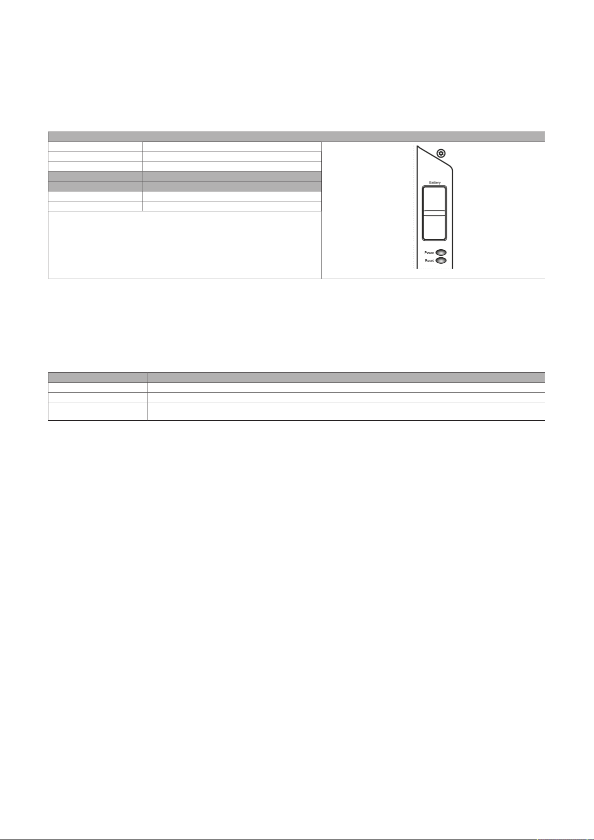
Technical data
4.1.6.6 Battery
The lithium battery (3 V, 950 mAh) ensures retention of the internal real-time clock (RTC), CMOS data and
remanent data of IF options with SRAM. It is located above the power and reset button behind the orange
cover. The service life time of the battery is at least 4 years1). The battery is subject to wear and should be
replaced regularly (after the specified service life at the latest) by changing the battery (see "Changing the
battery" on page 170).
Type Renata 3 V, 950 mAh
Removable Yes, accessible from the outside
Service life 4 years
Order number Short description
0AC201.91 Lithium batteries, 4 pcs., 3 V / 950 mAh, button cell
4A0006.00-000 Lithium battery, 1 pc., 3 V / 950 mAh, button cell
1) At 50°C, 8.5 µA for the components being supplied and self-discharge of 40%. If an interface option with SRAM or POWERLINK is installed, the
service life is 2½ years.
1)
Batteries
-
Battery
The battery state is determined by the system immediately after the device is switched on and subsequently
every 24 hours. During the measurement, the battery is subjected to a brief load (approx. 1 second) and then
assessed. The determined battery state is displayed on the BIOS Setup screens (Advanced - OEM Features -
"Mainboard" on page 125) and in the ADI Control Center but can also be read out in a customer application
via the ADI library.
Battery state Explanation
N/A The hardware or firmware used is too old and does not support readout.
GOOD Data retention is ensured.
BAD As soon as the battery capacity is recognized as BAD (insufficient), retention of data is ensured for approximately another
500 hours. The battery must be replaced.
When changing the battery, data is retained for approximately 10 minutes by a capacitor.
40 Automation PC 3200 User's manual V1.00
Page 41
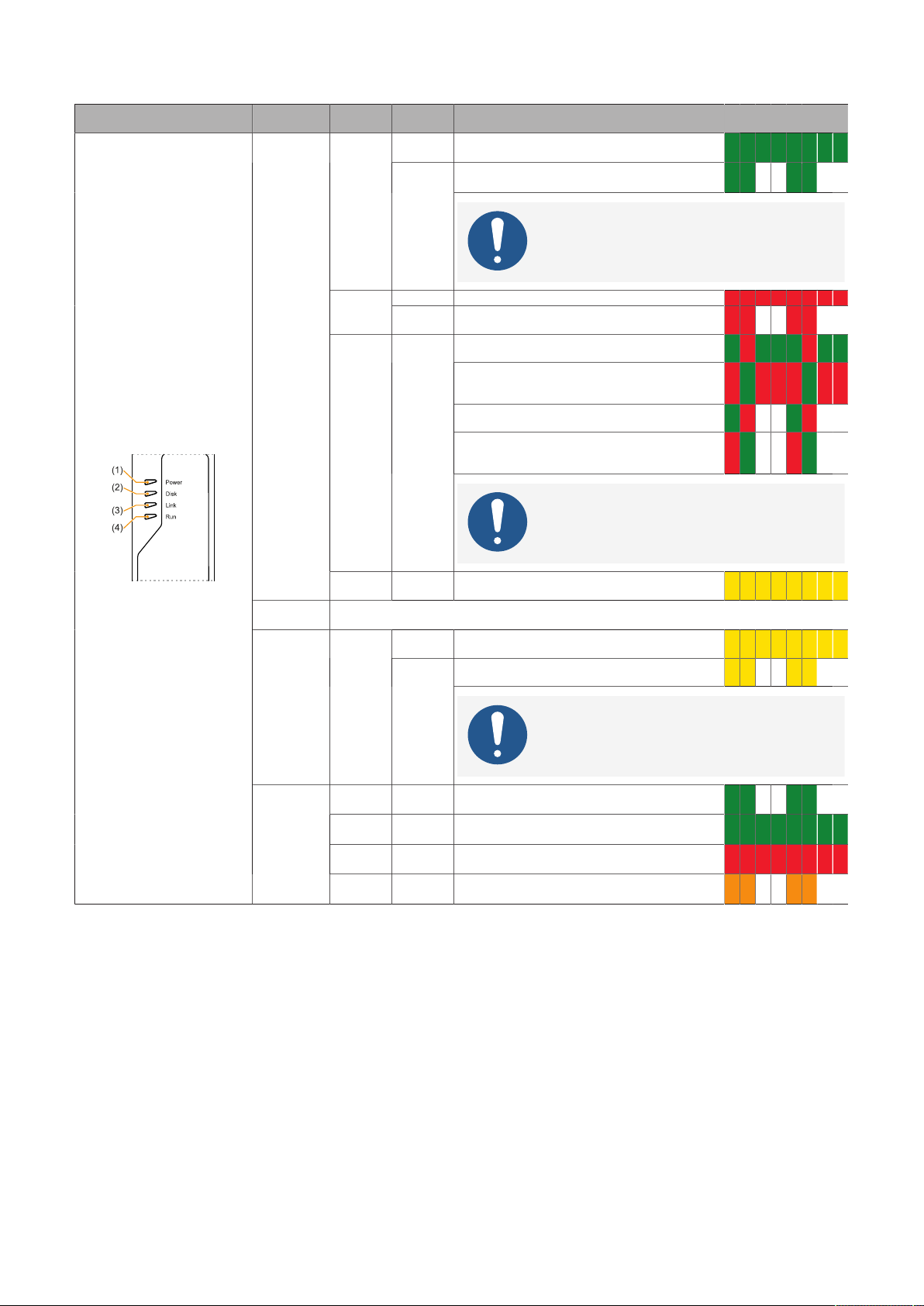
4.1.6.7 LED status indicators
Technical data
Assignment LED Color Status Explanation LED status
(1):
Power
Green
On Power supply OK
Blinking
The device is started up; the battery state is BAD.
indicators
Information:
For additional information, see "Battery" on page
40.
Red
Red-Green Blinking
On The system is in power saving mode (standby).
Blinking The MTCX is running; the battery state is "BAD". The
system is in power saving mode (standby).
Faulty or incomplete BIOS, MTCX or I/O FPGA up-
date, battery state OK, power supply OK
Faulty or incomplete BIOS, MTCX or I/O FPGA up-
date, battery state OK, power saving mode (stand-
2)
by)
Faulty or incomplete BIOS, MTCX or I/O FPGA up-
date, battery state BAD, power supply OK
Faulty or incomplete BIOS, MTCX or I/O FPGA
update, battery state BAD, power saving mode
(standby)
2)
2)
2)
Information:
An update must be performed again.
1)
Yellow On Power supply not OK. The system is running in UPS
(2):
Disk
(3):
3)
Link
(4):
Run
1) Two columns form 1 interval of 500 ms each.
2) S5: Soft-off
S4: Hibernate (suspend-to-disk)
3) Only active in conjunction with an SDL4 link module.
Reserved
Yellow
Green Blinking Automation Runtime is starting up.
Green On Application running
Red On Application in SERVICE mode
Orange Blinking A license violation has occurred.
mode.
On Indicates an active SDL4 connection on the IF op-
Blinking
tion 3 slot.
An active SDL4 connection was interrupted due to
voltage loss on the panel.
Information:
Check the power supply or power connection of the
connected panel.
Controlled by Automation Runtime.
Controlled by Automation Runtime.
Controlled by Automation Runtime.
Automation PC 3200 User's manual V1.00 41
Page 42
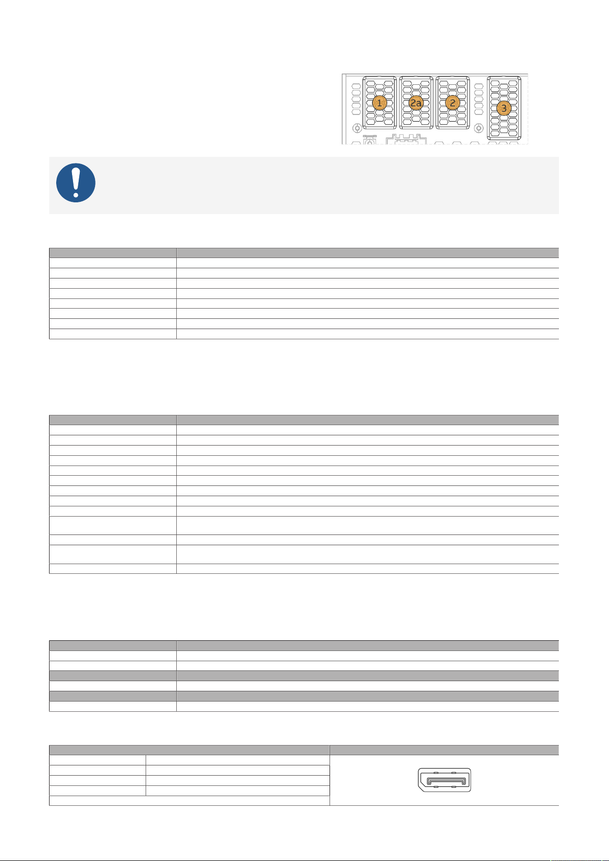
Technical data
4.1.6.8 IF options
The system units have 3 slots for interface options:
•
(1): IF option 1
•
(2) + (2a): IF option 2 + IF option 2 add-on
•
(3): IF option 3
Information:
For information about replacing or installing an interface option, see section "Installing
the interface option and DDR4 SDRAM" on page 173.
4.1.6.8.1 IF option 1 slot
Order number Interface option - Short description
5AC901.I232-00
5AC901.I485-00
5AC901.ICAN-01
5AC901.IHDA-00 Interface card - 1x audio interface (1x MIC / 1x Line In / 1x OUT) - For APC910/PPC900/APC3x00/PPC3x00
5AC901.IRDY-00 Interface card - Ready relay - For APC910/PPC900/APC3x00/PPC3x00
5AC901.ISIO-00 Interface card - System I/O - For APC910/PPC900/APC3x00/PPC3x00
5AC901.IUPS-00
5AC901.IUPS-01
1) Simultaneous operation with 5ACCIF02.ISS0-000 in the IF option 2 slot is not possible.
2) Simultaneous operation of 2 interface options with a legacy CAN interface in slots IF1 and IF2 is not possible.
3) UPS IF option 5AC901.IUPS-00 is only permitted to be operated with battery unit 5AC901.BUPS-00!
4) UPS IF option 5AC901.IUPS-01 is only permitted to be operated with battery unit 5AC901.BUPS-01!
1)
1)
2)
3)
4)
Interface card - 1x RS232 - For APC910/PPC900/APC3x00/PPC3x00
Interface card - 1x RS232/RS422/RS485 interface - For APC910/PPC900/APC3x00/PPC3x00
Interface card - 1x CAN interface - For APC910/PPC900/APC3x00/PPC3x00
UPS - For 4.5 Ah battery
UPS - For 2.2 Ah battery
4.1.6.8.2 IF option 2 slot
Order number Interface option - Short description
5AC901.I232-00 Interface card - 1x RS232 interface - For APC910/PPC900/APC3x00/PPC3x00
5AC901.I485-00 Interface card - 1x RS232/RS422/RS485 interface - For APC910/PPC900/APC3x00/PPC3x00
5AC901.ICAN-01
5AC901.IETH-00 Interface card - 1x Ethernet 10/100/1000 - For APC910/PPC900/APC3x00/PPC3x00
5AC901.IPLK-00 Interface card - 1x POWERLINK interface - 2 MB SRAM - For APC910/PPC900/APC3x00/PPC3x00
5AC901.ISRM-00 Interface card - 2 MB SRAM - For APC910/PPC900/APC3x00/PPC3x00
5AC901.IRDY-00 Interface card - Ready relay - For APC910/PPC900/APC3x00/PPC3x00
5AC901.ISIO-00 Interface card - System I/O - For APC910/PPC900/APC3x00/PPC3x00
5ACCIF02.CANE-000
5ACCIF02.FPLK-000
5ACCIF02.FPLS-000
5ACCIF02.FPSC-000
5ACCIF02.ISS0-000
1) Simultaneous operation of 2 interface options with a legacy CAN interface in slots IF1 and IF2 is not possible.
2) These IF options use the IF option 2 and IF option 2 add-on slot.
3) Simultaneous operation with 5AC901.I232-00 or 5AC901.I485-00 in the IF option 1 slot is not possible.
1)
1)2)
2)
2)
2)
2)3)
Interface card - 1x CAN interface - For APC910/PPC900/APC3x00/PPC3x00
Interface card - 1x CAN interface (SJA1000) - 1x ETH 10/100/1000 - For APC3x00/PPC3x00
Interface card - 1x POWERLINK interface - 2 MB SRAM - Integrated 2-port hub - Ring redundancy - POWERLINK
managing or controlled mode - PRC function - For APC3x00/PPC3x00
Interface card - 2 MB SRAM - 1x RS232 interface - 1x POWERLINK interface - For APC3x00/PPC3x00
Interface card - 2 MB SRAM - 1x RS232 interface - 1x CAN interface - 1x POWERLINK interface - 1x X2X - For APC3x00/
PPC3x00
Interface card - 2x RS232/RS422/RS485 interface - For APC3x00/PPC3x00
4.1.6.8.3 IF option 3 slot
Order number Graphics option - Short description
5ACCLI02.DPO0-000 Graphics option - 1x DisplayPort transmitter (version 1.2) - For APC3x00/PPC3x00
5ACCLI02.SD40-000 Graphics option - 1x SDL4 transmitter (max. 1920 x 1080) - For APC3x00/PPC3x00
Order number Interface option - Short description
5ACCIF04.FPLK-000 Interface card - 1x POWERLINK interface - For APC3x00/PPC3x00.
Order number Mass storage option - Short description
5ACCMS01.MDT2-000 Adapter card for M.2 mass storage device - For APC3x00/PPC3x00
4.1.6.9 DisplayPort interface
Variant DP 1.2, female
Resolution Max. 4K, 60 Hz, HDR
Cable length Depends on the resolution and refresh rate
Available video signals DisplayPort, DVI, HDMI
42 Automation PC 3200 User's manual V1.00
Description Figure
-
Page 43
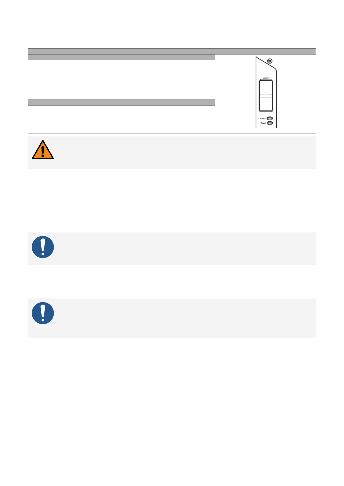
4.1.6.10 Power and reset buttons
Both buttons can be pressed without any tools.
Power button
The power button offers full ATX power supply unit support and has various configurable functions.
•
Short press: Switches the PC on or off or performs the action configured in the operating
system when pressing the power button (shutdown, sleep, etc.).
•
Long press (approx. 4 s): The ATX power supply unit switches off the PC without shutting
it down.
Pressing the power button does not reset the MTCX processor.
Reset button
Pressing the reset button triggers a hardware/PCI reset. The PC is restarted.
During a reset, the MTCX processor is not reset.
Description
Warning!
Switching off the power without shutting down or resetting the system can result in data
loss!
4.1.6.11 Trusted Platform Module (TPM)
Technical data
A Trusted Platform Module (TPM 2.0) is located on the system unit. A TPM is an additional chip integrated
directly into the system hardware that adds important safety functions to the device. In particular, the
TPM enables improved protection of the PC against unauthorized tampering by third parties. These safety
functions are supported by current operating systems, such as Windows 10.
Enabling the Trusted Platform Module
Information:
Before enabling the TPM, possible country-specific usage restrictions or regulations must
be checked.
Using the Trusted Platform Module
The TPM can be used together with the drive encryption BitLocker in Windows 10, for example. To do this,
follow the instructions in the operating system.
Information:
If the password for data encryption is lost, it is not possible to decrypt the data, e.g. after
a BIOS update or TPM firmware update. Access to the encrypted drive is lost. Passwords
must be carefully stored and protected from unauthorized access.
Automation PC 3200 User's manual V1.00 43
Page 44

Technical data
4.2 Individual components
Information:
The following specified characteristic data, features and limit values are only valid for
these individual components and may differ from those of the complete system. The specific data specified for the complete system applies to the complete system in which an
individual component is used.
4.2.1 System units
4.2.1.1 5APC3200.RPLx-000
4.2.1.1.1 General information
APC3200 system units consist of a CPU board, housing and mounting plate. Several interfaces are included,
and 3 interface options can be additionally installed. The main memory can be replaced or expanded.
•
Intel Core i-series processors
•
DDR4 memory
•
Intel HD Graphics
•
2x CFexpress slots
•
Slots for 3 interface options
•
Replaceable and expandable main memory
44 Automation PC 3200 User's manual V1.00
Page 45
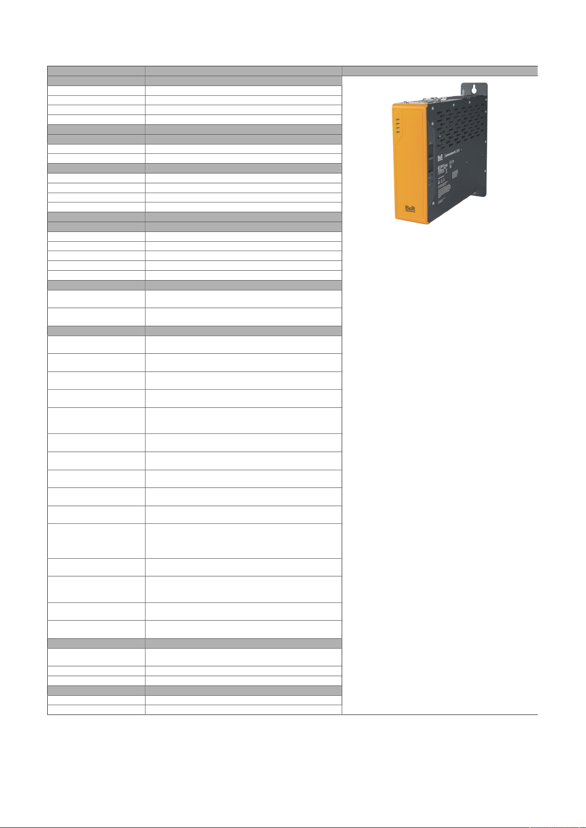
4.2.1.1.2 Order data
Technical data
Order number Short description Figure
5APC3200.RPL0-000 APC3200 system unit - Intel U300E 1.1 GHz - 5 core
5APC3200.RPL1-000 APC3200 system unit - Intel Core i3 1315URE 1.2 GHz - 6 core
5APC3200.RPL2-000 APC3200 system unit - Intel Core i5 1345URE 1.4 GHz - 10 core
5APC3200.RPL3-000 APC3200 system unit - Intel Core i7 1365URE 1.7 GHz - 10 core
5ACCFF01.0000-000 APC3x00 front cover - Orange - With B&R logo
5ACCFF01.0000-001 APC3x00 front cover - Dark gray - Without logo
5MMDDR.016G-05 SO-DIMM DDR4, 16384 MB
5MMDDR.032G-05 SO-DIMM DDR4, 32768 MB
5MMDDR.4096-05 SO-DIMM DDR4, 4096 MB
5MMDDR.8192-05 SO-DIMM DDR4, 8192 MB
5CFXPR.060G-20 CFexpress 60 GB TLC
5CFXPR.120G-20 CFexpress 120 GB TLC
5CFXPR.240G-20 CFexpress 240 GB TLC
5CFXPR.480G-20 CFexpress 480 GB TLC
5CFXPR.960G-20 CFexpress 960 GB TLC
5ACCLI02.DPO0-000 Graphics option - 1x DisplayPort transmitter (version 1.2) -
5ACCLI02.SD40-000 Graphics option - 1x SDL4 transmitter (max. 1920 x 1080) -
5AC901.I232-00 Interface card - 1x RS232 interface - For APC910/PPC900 -
5AC901.I485-00 Interface card - 1x RS232/RS422/RS485 interface - For
5AC901.ICAN-01 Interface card - 1x CAN interface (SJA1000) - For APC910/
5AC901.IETH-00 Interface card - 1x ETH 10/100/1000 - For APC910/PPC900 -
5AC901.IHDA-00 Interface card - 1x audio interface (1x MIC / 1x Line In / 1x
5AC901.IPLK-00 Interface card - 1x POWERLINK interface - 2 MB SRAM - For
5AC901.IRDY-00 Interface card - Ready relay - For APC910/PPC900 - For
5AC901.ISIO-00 Interface card - System I/O - For APC910/PPC900 - For
5AC901.ISRM-00 Interface card - 2 MB SRAM - For APC910/PPC900 - For
5ACCIF02.CANE-000 Interface card - 1x CAN interface (SJA1000) - 1x ETH
5ACCIF02.FPLK-000 Interface card - 1x POWERLINK interface - 2 MB SRAM - In-
5ACCIF02.FPLS-000 Interface card - 2 MB SRAM - 1x RS232 interface - 1x POWER-
5ACCIF02.FPSC-000 Interface card - 2 MB SRAM - 1x RS232 interface - 1x CAN in-
5ACCIF02.ISS0-000 Interface card - 2x RS232/RS422/RS485 interface - For
5ACCIF04.FPLK-000 Interface card - 1x POWERLINK interface - For APC3x00/
5ACCMS01.MDT2-000 Adapter card for M.2 mass storage - For APC3x00/PPC3x00
5ACCMSM2.0512-000 512 GB M.2 SSD MLC - Innodisk - SATA
5ACCMSM2.1024-000 1 TB M.2 SSD MLC - Innodisk - SATA
5AC901.IUPS-00 UPS - For 4.5 Ah battery
5AC901.IUPS-01 UPS - For 2.2 Ah battery
System units
Required accessories
Front covers
Main memory
Optional accessories
CFexpress cards
Graphics options
For APC3x00/PPC3x00 - For APC4100
For APC3x00/PPC3x00
Interface options
For APC3x00/PPC3x00 - For APC4100
APC910/PPC900 - For APC3x00/PPC3x00 - For APC4100
PPC900 - For APC3x00/PPC3x00 - For APC4100
For APC3x00/PPC3x00 - For APC4100
OUT) - For APC910/PPC900 - For APC3x00/PPC3x00 - For
APC4100
APC910/PPC900 - For APC3x00/PPC3x00 - For APC4100
APC3x00/PPC3x00 - For APC4100
APC3x00/PPC3x00 - For APC4100
APC3x00/PPC3x00 - For APC4100
10/100/1000 - For APC3x00/PPC3x00
tegrated 2-port hub - Ring redundancy - POWERLINK managing or controlled mode - PRC function - For APC3x00/
PPC3x00
LINK interface - For APC3x00/PPC3x00
terface - 1x POWERLINK interface - 1x X2X - For APC3x00/
PPC3x00
APC3x00/PPC3x00
PPC3x00 - For APC4100
Mass storage options
- For APC4100
Uninterruptible power supply
Automation PC 3200 User's manual V1.00 45
Page 46

Technical data
4.2.1.1.3 Technical data
Order number 5APC3200.RPL0-000 5APC3200.RPL1-000 5APC3200.RPL2-000 5APC3200.RPL3-000
General information
LEDs Power, Link, Run
B&R ID code 0x307B 0x307C 0x307D 0x307E
Cooling Passive via heat sink
Battery
Type Renata 950 mAh
Service life 4 years
Removable Yes
Variant Lithium ion
Power button Yes
Reset button Yes
Certifications
CE Yes
UKCA Yes
UL In preparation
Controller
Bootloader UEFI BIOS
Processor
Type Intel U300E Intel i3-1315URE Intel i5-1345URE Intel i7-1365URE
Clock frequency 1100 MHz 1200 MHz 1400 MHz 1700 MHz
Number of cores 5 6 10
Thermal design power (TDP) 15 W
Intel Smart Cache 8 MB 10 MB 12 MB
Intel 64 architecture Yes
Intel Turbo Boost Technology Yes
Intel Hyper-Threading Technology Yes
Intel Virtualization Technology
(VT-x)
Intel Virtualization Technology for
Directed I/O (VT-d)
Intel Speed Shift Technology Yes
Enhanced Intel SpeedStep Tech-
nology
Chipset Intel Raptor Lake U
Trusted Platform Module TPM 2.0
Real-time clock
Accuracy At 25°C: Typ. 12 ppm (1 second) per day
Battery-backed Yes
Power failure logic
Controller MTCX
Buffer time 10 ms
Memory
Removable Yes
Memory slot
Number of memory channels 2
Type DDR4 SDRAM
Memory size Max. 64 GB
Max. memory bandwidth 2666 MT/s
Graphics
Controller Intel UHD Intel Iris Xe (only with dual-channel RAM), Intel UHD
Color depth Max. 32-bit
DirectX support 12.1
OpenGL support 4.6
Power management ACPI 5.0
Interfaces
CFexpress slot
Quantity 2
Type Type B, PCIe Gen3 x2
USB
Quantity 5
Type 4x USB 3.2 Gen2
1x USB 2.0 (internal for Technology Guard)
Transfer rate Up to SuperSpeed+ (10 Gbit/s)
Ethernet
Quantity 2
Variant RJ45, shielded
Transfer rate 10/100/1000/2500 Mbit/s
DisplayPort
Quantity 1
Version 1.2
Slots
Interface option
5)
1)
Yes
Yes
Yes
2)
3)
4)
3
46 Automation PC 3200 User's manual V1.00
Page 47

Technical data
Order number 5APC3200.RPL0-000 5APC3200.RPL1-000 5APC3200.RPL2-000 5APC3200.RPL3-000
Support
Software
Automation Studio V6.3 or later
Electrical properties
Nominal voltage 24 VDC, SELV/PELV
Nominal current Max. 5.5 A
Operating voltage 24 VDC ±25%
Inrush current Max. 80 A for < 300 µs
Overvoltage category per EN
II
61131-2
Galvanic isolation Yes
Operating conditions
Pollution degree per EN 61131-2 Pollution degree 2
Degree of protection per EN 60529 IP20
Ambient conditions
Elevation
Operation Max. 3000 m (component-dependent)
Mechanical properties
Dimensions
9)
Width 54 mm
Height 173.5 mm
Depth 248.3 mm
Weight 1470 g
1) At 50°C, 8.5 µA for the components being supplied and self-discharge of 40%. If an interface option with SRAM or POWERLINK is installed, the
service life is 2 1/2 years.
2) At max. specified ambient temperature: Typ. 58 ppm (5 seconds) - worst case 220 ppm (19 seconds).
3) Maintenance Controller Extended
4) SuperSpeed+ (10 Gbit/s) is only possible with USB 3.2 Gen2.
5) The interface option can be replaced.
6) IEC 61010-2-201 requirements must be observed.
7) Only if all interface covers are installed.
8) The maximum ambient temperature is typically derated 1°C per 1000 meters starting at 500 m above sea level.
9) All dimensions without mounting plate.
6)
7)
8)
Automation PC 3200 User's manual V1.00 47
Page 48
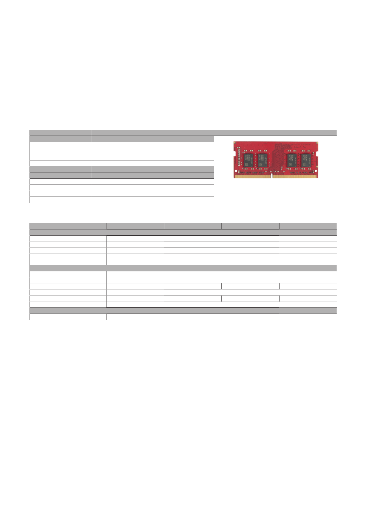
Technical data
4.2.2 Main memory
4.2.2.1 5MMDDR.xxxx-0x
4.2.2.1.1 General information
These 260-pin DDR4 main memory modules operate with a data rate of max. 3200 MHz and are available
in memory sizes ranging from 4 GB to 32 GB.
If two main memory modules of identical size (e.g. 16 GB) are connected to the CPU board, then dual-channel
memory technology is supported.
4.2.2.1.2 Order data
Order number Short description Figure
5MMDDR.4096-05 SO-DIMM DDR4, 4096 MB
5MMDDR.8192-05 SO-DIMM DDR4, 8192 MB
5MMDDR.016G-05 SO-DIMM DDR4, 16384 MB
5MMDDR.032G-05 SO-DIMM DDR4, 32768 MB
5ACCRDDR.016G-05 HMI SO-DIMM DDR4-3200 16384 MB
5ACCRDDR.032G-05 HMI SO-DIMM DDR4-3200 32768 MB
5ACCRDDR.4096-05 HMI SO-DIMM DDR4-3200 4096 MB
5ACCRDDR.8192-05 HMI SO-DIMM DDR4-3200 8192 MB
Main memory
Optional accessories
Main memory
4.2.2.1.3 Technical data
Order number 5MMDDR.4096-05 5MMDDR.8192-05 5MMDDR.016G-05 5MMDDR.032G-05
General information
Certifications
CE Yes
UKCA Yes
UL cULus E115267
Controller
Memory
Type SO-DIMM DDR4 SDRAM
Memory size 4 GB 8 GB 16 GB 32 GB
Construction 260-pin
Organization 512M x 64-bit 1024M x 64-bit 2048M x 64-bit 4096M x 64-bit
Speed DDR4-3200 (PC4-3200)
Endurance
Error-correcting code (ECC) No
Industrial control equipment
48 Automation PC 3200 User's manual V1.00
Page 49
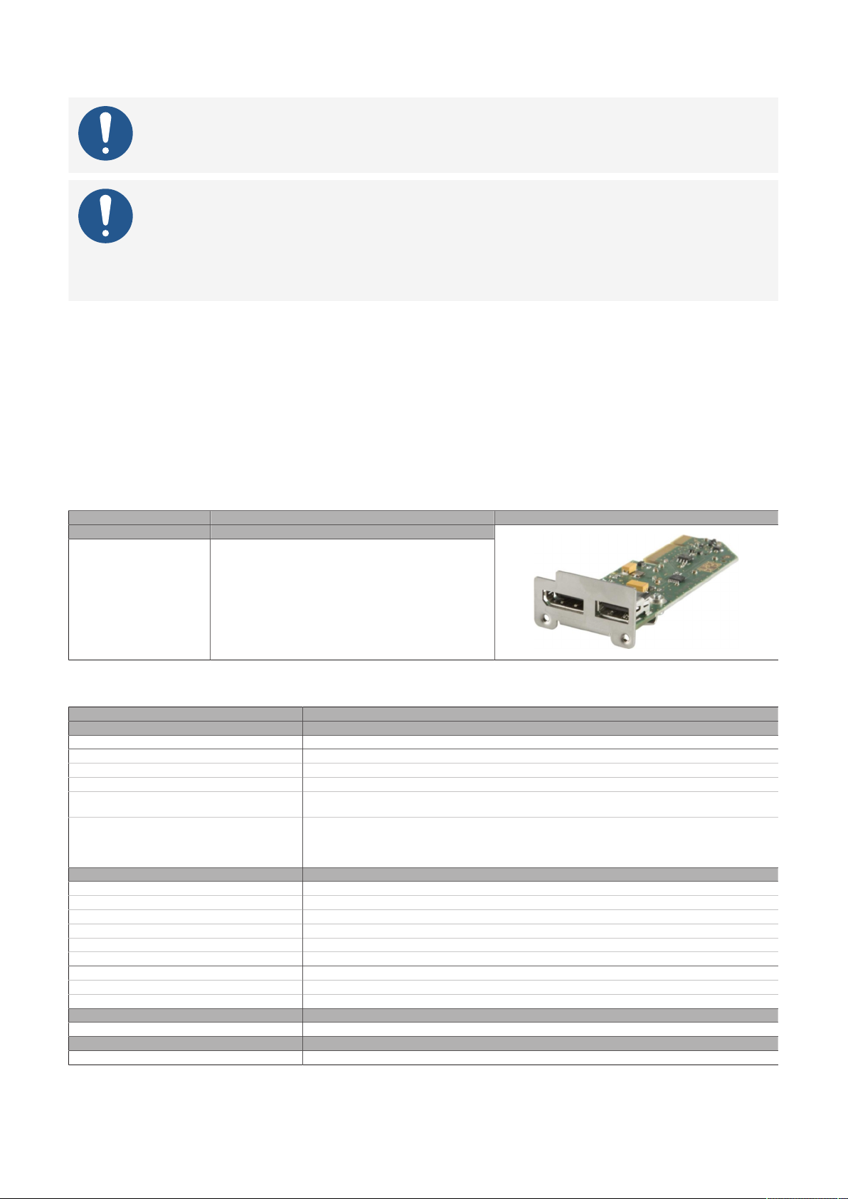
4.2.3 Graphics options
Information:
Graphics options can only be operated on the "IF option 3 slot" on page 42 slot.
Information:
For information about replacing or installing a graphics option, see section "Installing the
interface option and DDR4 SDRAM" on page 173.
After installation or replacement, it may be necessary to load the defaults settings in BIOS
(see "Exit" on page 146).
4.2.3.1 5ACCLI02.DPO0-000
4.2.3.1.1 General information
Graphics option 5ACCLI02.DPO0-000 is equipped with a DisplayPort and USB 2.0 interface.
•
DisplayPort interface
•
USB 2.0 interface
•
Compatible with APC3x00/PPC3x00 and APC4100
Technical data
4.2.3.1.2 Order data
Order number Short description Figure
5ACCLI02.DPO0-000 Graphics option - 1x DisplayPort transmitter (version 1.2) -
Graphics options
For APC3x00/PPC3x00 - For APC4100
4.2.3.1.3 Technical data
Order number 5ACCLI02.DPO0-000
General information
B&R ID code 0xEEE6
Certifications
CE Yes
UKCA Yes
UL cULus E115267
HazLoc cULus HazLoc E180196
Interfaces
USB
Quantity 1
Type USB 2.0
Variant Type A
Transfer rate Low speed (1.5 Mbit/s), full speed (12 Mbit/s) to high speed (480 Mbit/s)
Current-carrying capacity Max. 0.5 A
DisplayPort
Quantity 1
Version 1.2
Electrical properties
Power consumption 3 W
Operating conditions
Pollution degree per EN 61131-2 Pollution degree 2
Industrial control equipment
Industrial control equipment
for hazardous locations
Class I, Division 2, Groups ABCD, T4
Automation PC 3200 User's manual V1.00 49
Page 50
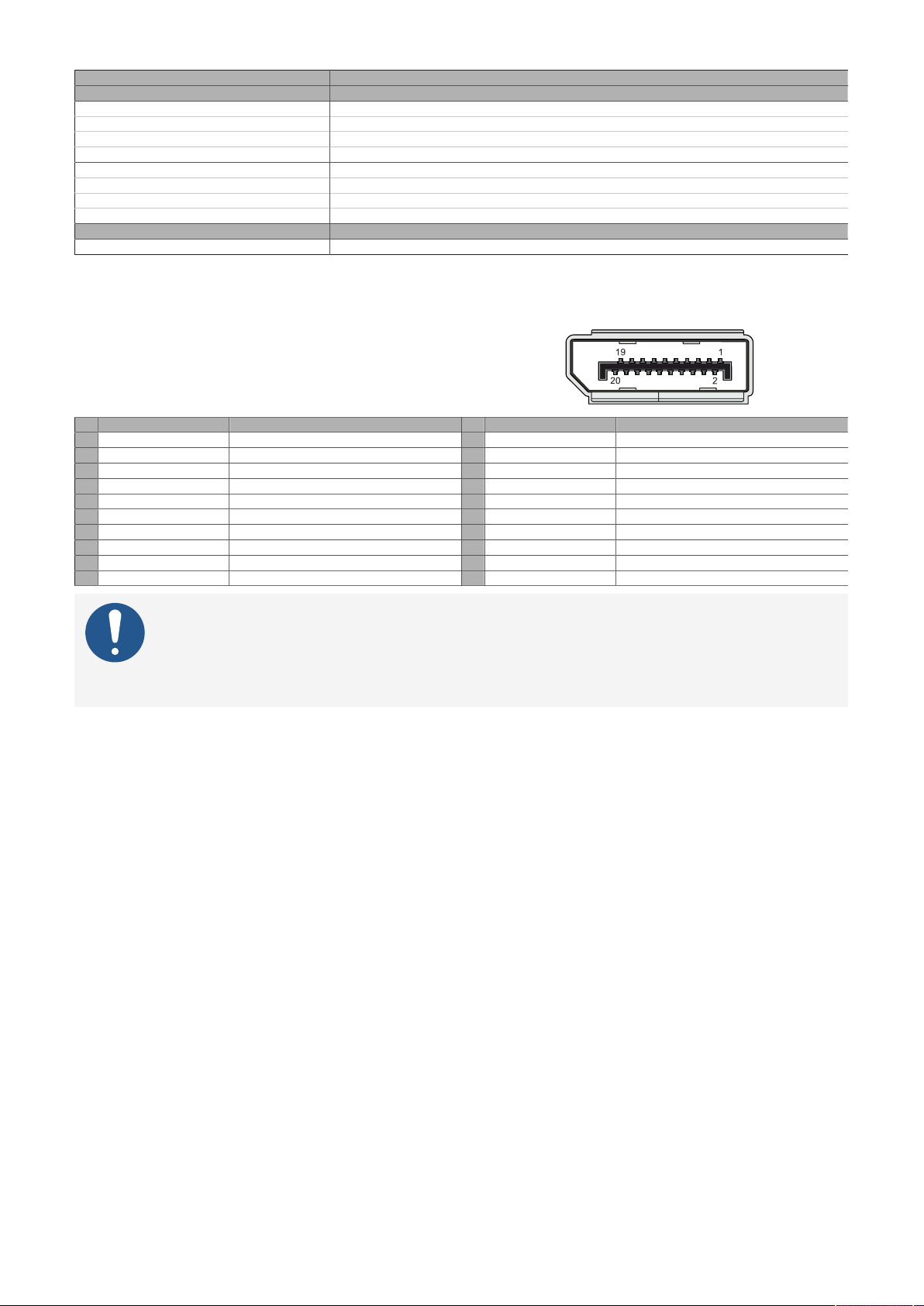
Technical data
Order number 5ACCLI02.DPO0-000
Ambient conditions
Temperature
Operation 0 to 60°C
Storage -20 to 60°C
Transport -20 to 60°C
Relative humidity
Operation 5 to 90%, non-condensing
Storage 5 to 95%, non-condensing
Transport 5 to 95%, non-condensing
Mechanical properties
Weight Approx. 30 g
1) For detailed information, see the temperature tables in the user's manual.
1)
4.2.3.1.3.1 DisplayPort interface
The DisplayPort interface is 20-pin (female) and can
be operated with DisplayPort, DVI or HDMI transmission technologies.
Pin Pinout Description Pin Pinout Description
1 DP_LANE0+ DisplayPort lane 0 (positive) 11 GND Ground
2 GND Ground 12 DP_LANE3- DisplayPort lane 3 (negative)
3 DP_LANE0- DisplayPort lane 0 (negative) 13 CONFIG1 Configuration pin 1 (connected to ground)
4 DP_LANE1+ DisplayPort lane 1 (positive) 14 CONFIG2 Configuration pin 2 (connected to ground)
5 GND Ground 15 DP_AUX+ Auxiliary channel (positive)
6 DP_LANE1- DisplayPort lane 1 (negative) 16 GND Ground
7 DP_LANE2+ DisplayPort lane 2 (positive) 17 DP_AUX- Auxiliary channel (negative)
8 GND Ground 18 DP_HPD# Hot plug detection
9 DP_LANE2- DisplayPort lane 2 (negative) 19 RETURN Return for power
10 DP_LANE3+ DisplayPort lane 3 (positive) 20 DP_PWR Power for connector
Information:
Hot plugging output devices on the interface for service purposes is supported by the
hardware and graphic drivers of approved operating systems.
A maximum of 10,000 mating cycles are specified for this interface.
50 Automation PC 3200 User's manual V1.00
Page 51
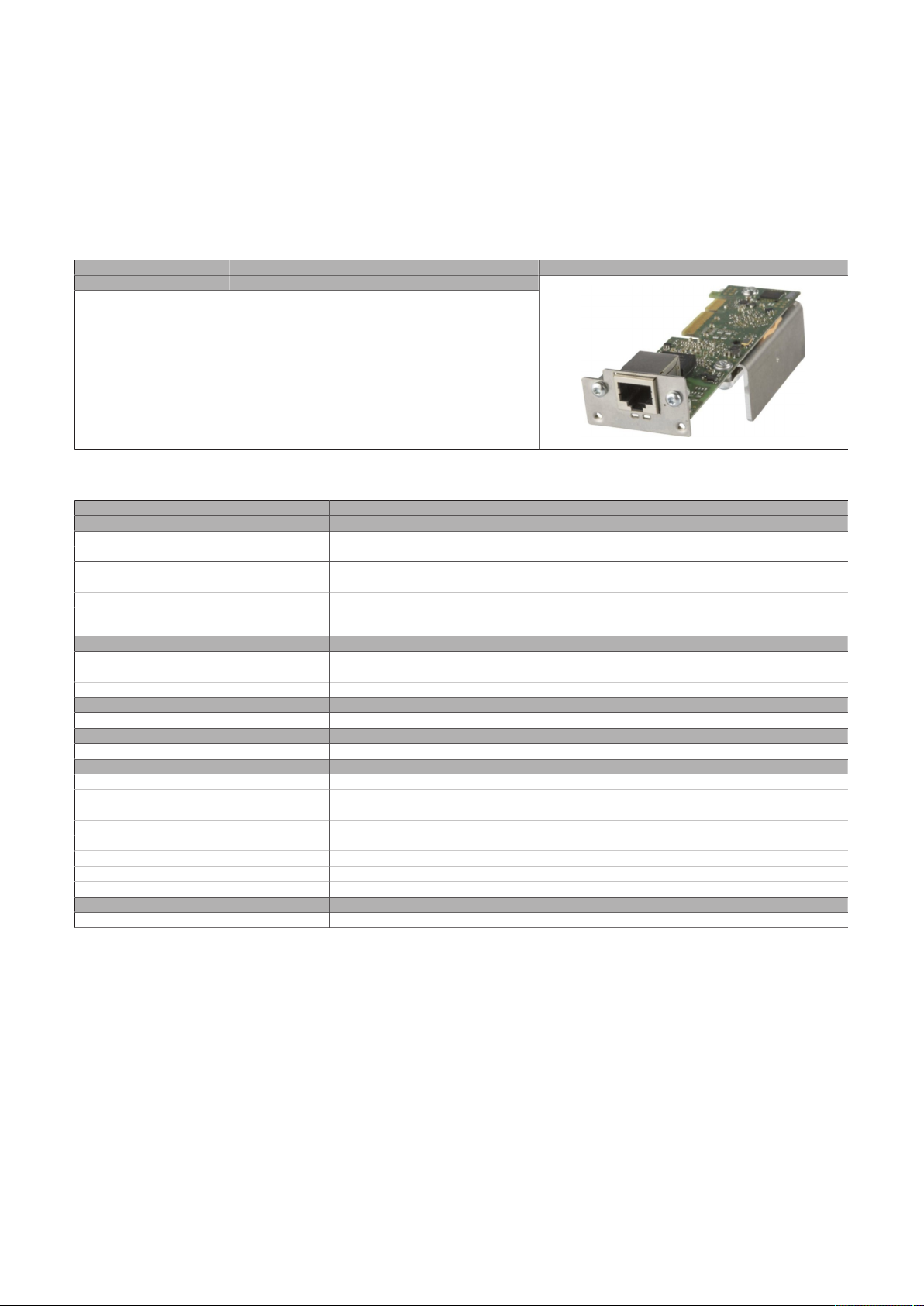
4.2.3.2 5ACCLI02.SD40-000
4.2.3.2.1 General information
Graphics option 5ACCLI02.SD40-000 is equipped with an SDL4 interface.
•
SDL4 interface
•
Compatible with APC3x00/PPC3x00
4.2.3.2.2 Order data
Technical data
Order number Short description Figure
5ACCLI02.SD40-000 Graphics option - 1x SDL4 transmitter (max. 1920 x 1080) -
Graphics options
For APC3x00/PPC3x00
4.2.3.2.3 Technical data
Order number 5ACCLI02.SD40-000
General information
LEDs Status, Link
B&R ID code 0xECCC
Certifications
CE Yes
UKCA Yes
UL cULus E115267
Interfaces
SDL4 Out
Variant RJ45, shielded
Type SDL4
Electrical properties
Power consumption 4.5 W
Operating conditions
Pollution degree per EN 61131-2 Pollution degree 2
Ambient conditions
Temperature
Operation 0 to 55°C
Storage -20 to 60°C
Transport -20 to 60°C
Relative humidity
Operation 5 to 90%, non-condensing
Storage 5 to 95%, non-condensing
Transport 5 to 95%, non-condensing
Mechanical properties
Weight Approx. 38 g
1) For detailed information, see the temperature tables in the user's manual.
Industrial control equipment
1)
Automation PC 3200 User's manual V1.00 51
Page 52
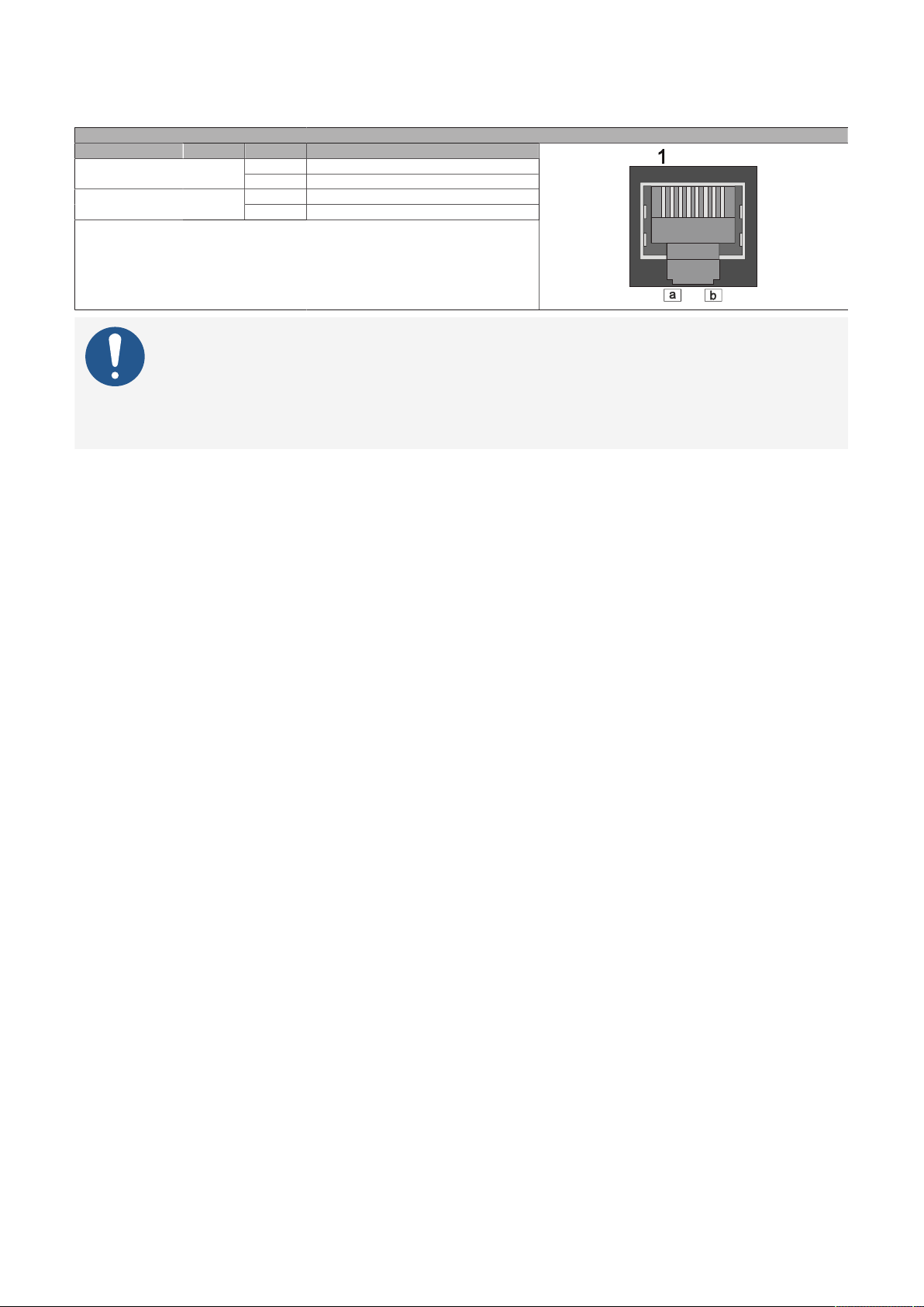
Technical data
4.2.3.2.3.1 SDL4 interface
The SDL4 interface is a RJ45 connector (female) and operated with SDL4 transmission technology.
SDL4 LEDs
LED Color Status Explanation
On Indicates an active SDL4 connection.Link (a) Yellow
Off No active SDL4 connection.
On The SDL4 connection is established and OK.Status (b) Yellow
Blinking No active SDL4 connection.
-
Information:
Hot plugging output devices on the interface for service purposes is supported by the
hardware and graphic drivers of approved operating systems. Recalibration may be required for touch screen devices.
A maximum of 500 mating cycles are specified for this interface.
4.2.3.2.3.2 Cable lengths and resolutions for SDL4 transfer
The maximum cable length for SDL4 transfer with a B&R SDL3/SDL4 cable is 100 meters (regardless of the
resolution of the panel).
52 Automation PC 3200 User's manual V1.00
Page 53
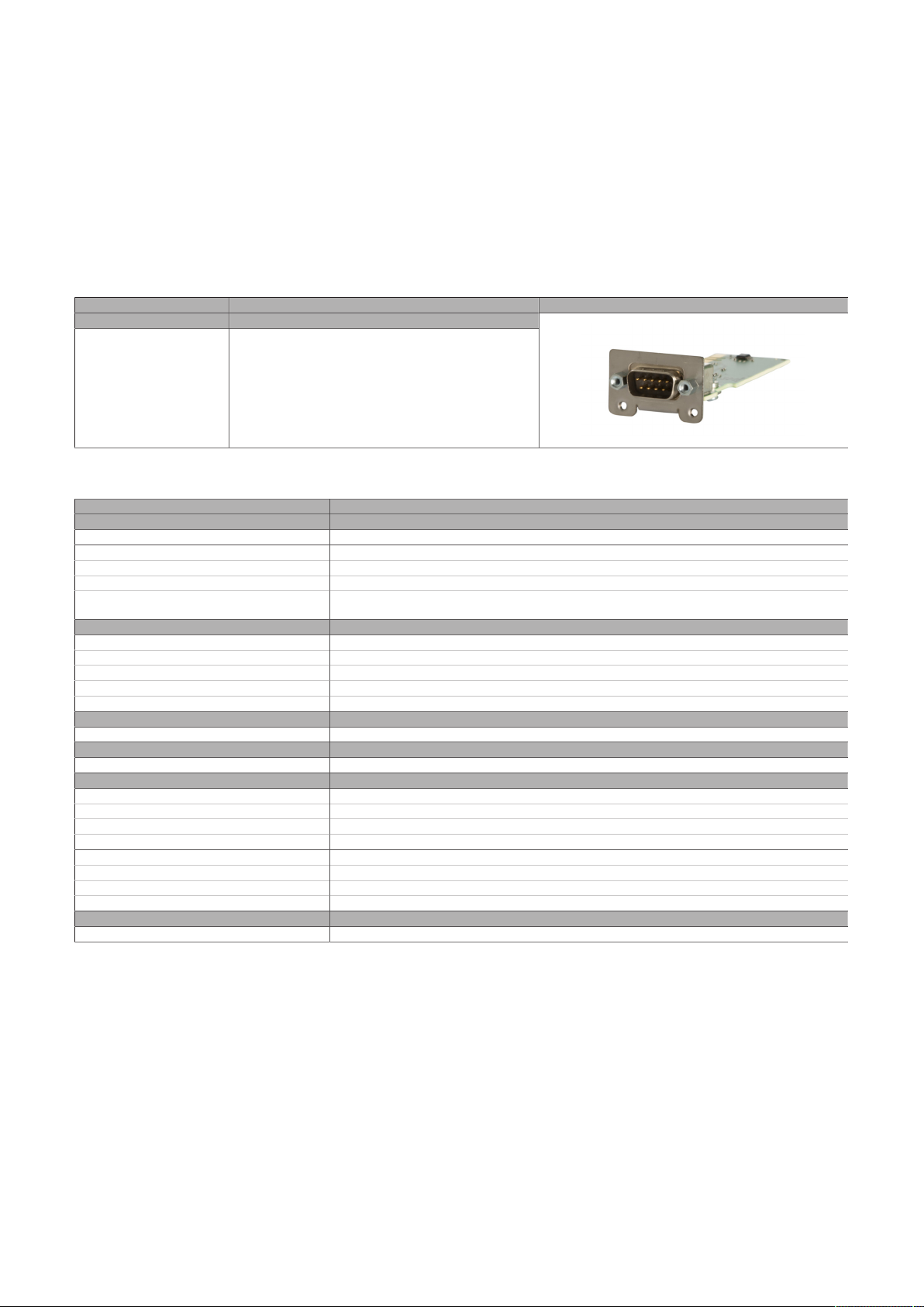
4.2.4 Interface options
4.2.4.1 5AC901.I232-00
4.2.4.1.1 General information
Interface option 5AC901.I232-00 is equipped with an RS232 interface.
•
1x RS232 interface
•
Compatible with APC910/PPC900, APC3x00/PPC3x00 and APC4100
4.2.4.1.2 Order data
Technical data
Order number Short description Figure
5AC901.I232-00 Interface card - 1x RS232 interface - For APC910/PPC900 -
Interface options
For APC3x00/PPC3x00 - For APC4100
4.2.4.1.3 Technical data
Order number 5AC901.I232-00
General information
B&R ID code 0xF400
Certifications
CE Yes
UKCA Yes
UL cULus E115267
Interfaces
COM
Type RS232, modem supported, not galvanically isolated
Variant DSUB, 9-pin, male
UART 16550-compatible, 16-byte FIFO buffer
Max. baud rate 115 kbit/s
Electrical properties
Power consumption 1 W
Operating conditions
Pollution degree per EN 61131-2 Pollution degree 2
Ambient conditions
Temperature
Operation 0 to 60°C
Storage -20 to 60°C
Transport -20 to 60°C
Relative humidity
Operation 5 to 90%, non-condensing
Storage 5 to 95%, non-condensing
Transport 5 to 95%, non-condensing
Mechanical properties
Weight Approx. 30 g
1) For detailed information, see the temperature tables in the user's manual.
Industrial control equipment
1)
Automation PC 3200 User's manual V1.00 53
Page 54
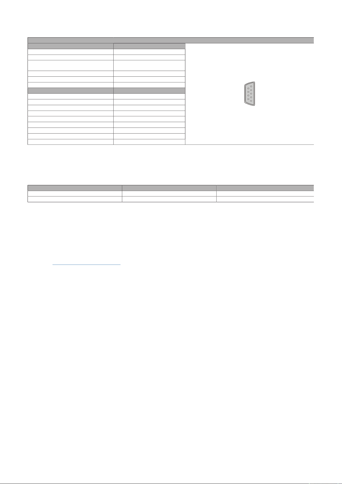
Technical data
5
1
9
6
4.2.4.1.3.1 Pinout
Serial interface COM
RS232
Variant DSUB, 9-pin, male
Type RS232, modem supported
UART 16550-compatible,
16-byte FIFO buffer
Galvanic isolation No
Transfer rate Max. 115 kbit/s
Bus length Max. 15 m
Pin Pinout
1 DCD
2 RXD
3 TXD
4 DTR
5 GND
6 DSR
7 RTS
8 CTS
9 RI
1) The interfaces, etc. available on the device or module have been numbered for the purpose of clear differentiation. This numbering may deviate
from the numbering used by the respective operating system, however.
1)
4.2.4.1.3.2 I/O address and IRQ
When operated in the xPC3200:
Slot I/O address IRQ
IF option 1 (COM A) 3F8h - 3FFh 4
IF option 2 (COM B) 2F8h - 2FFh 3
4.2.4.1.3.3 Cable data
For more detailed information about the transfer rate, bus length or cable requirements for the respective
interfaces/buses, see "Cable data" on page 188.
4.2.4.1.4 Driver support
Drivers for approved operating systems are available for download in the Downloads section of the B&R
website (www.br-automation.com) (if required and not already included in the operating system).
Approved operating systems:
•
Automation Runtime
•
Linux for B&R
•
Windows 10
54 Automation PC 3200 User's manual V1.00
Page 55
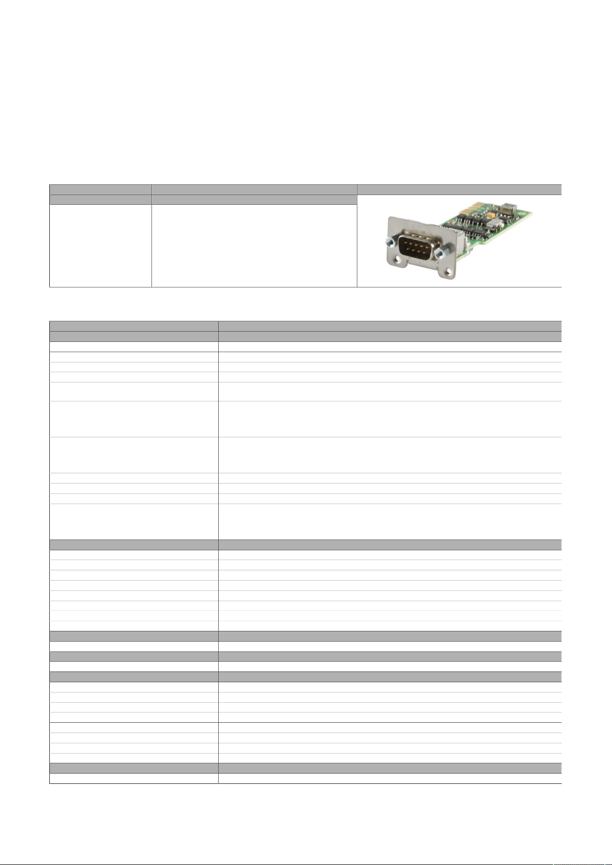
Technical data
4.2.4.2 5AC901.I485-00
4.2.4.2.1 General information
Interface option 5AC901.I485-00 is equipped with an RS232/RS422/RS485 interface. The operating mode
(RS232/RS422/RS485) is selected automatically depending on the electrical connection.
•
1x RS232/RS422/RS485 interface
•
Compatible with APC910/PPC900, APC3x00/PPC3x00 and APC4100
4.2.4.2.2 Order data
Order number Short description Figure
5AC901.I485-00 Interface card - 1x RS232/RS422/RS485 interface - For
Interface options
APC910/PPC900 - For APC3x00/PPC3x00 - For APC4100
4.2.4.2.3 Technical data
Order number 5AC901.I485-00
General information
B&R ID code 0xD84A
Certifications
CE Yes
UKCA Yes
UL cULus E115267
HazLoc cULus HazLoc E180196
DNV Temperature: B (0 to 55°C)
LR ENV3
KR Yes
ABS Yes
BV EC31B
Interfaces
COM
Type RS232/RS422/RS485, galvanically isolated
Variant DSUB, 9-pin, male
UART 16550-compatible, 16-byte FIFO buffer
Max. baud rate 115 kbit/s
Terminating resistor
Type Can be switched on and off with slide switch
Default setting Off
Electrical properties
Power consumption 1 W
Operating conditions
Pollution degree per EN 61131-2 Pollution degree 2
Ambient conditions
Temperature
Operation 0 to 55°C
Storage -20 to 60°C
Transport -20 to 60°C
Relative humidity
Operation 5 to 90%, non-condensing
Storage 5 to 95%, non-condensing
Transport 5 to 95%, non-condensing
Mechanical properties
Weight Approx. 34 g
1) For detailed information, see the temperature tables in the user's manual.
Industrial control equipment
Industrial control equipment
for hazardous locations
Class I, Division 2, Groups ABCD, T4
Humidity: B (up to 100%)
Vibration: A (0.7 g)
EMC: B (bridge and open deck)
Temperature: 5 - 55°C
Vibration: 0.7 g
EMC: Bridge and open deck
1)
Automation PC 3200 User's manual V1.00 55
Page 56
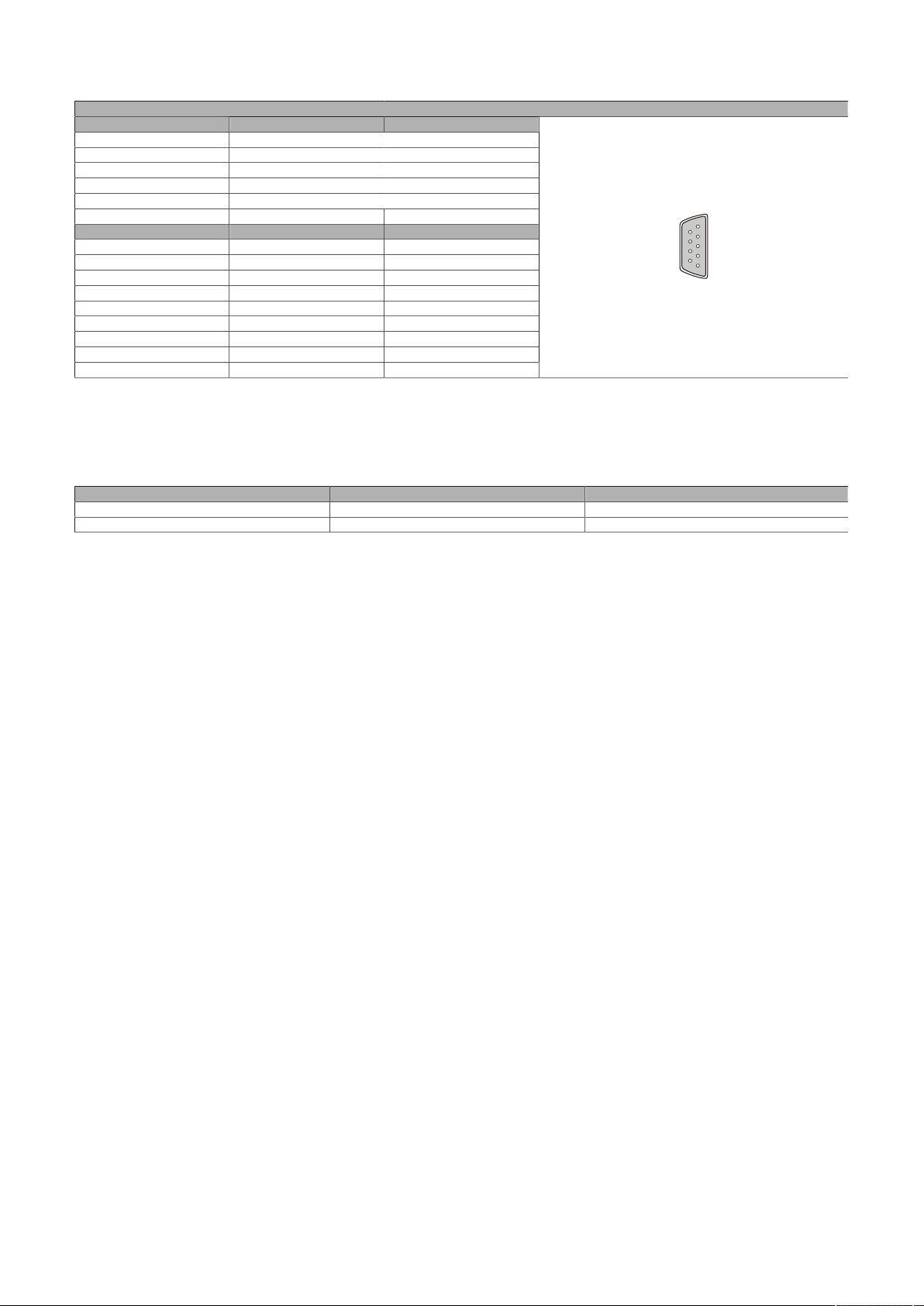
Technical data
5
1
9
6
4.2.4.2.3.1 Pinout
Variant DSUB, 9-pin, male
Type RS232, not modem supported
UART 16550-compatible, 16-byte FIFO buffer
Galvanic isolation Yes
Transfer rate Max. 115 kbit/s
Bus length Max. 15 m Max. 1200 m
Pin RS232 - Pinout
1 NC
2 RXD NC
3 TXD NC
4 NC TXD
5 GND GND
6 NC RXD\
7 RTS NC
8 CTS NC
9 NC RXD
1) Pins marked "NC" are not permitted to be used or connected in the respective operating mode.
2) Not connected.
RS232 RS422/485
1)
2)
Serial interface COM
RS422 - Pinout
TXD\
1)
4.2.4.2.3.2 I/O address and IRQ
When operated in the xPC3200:
Slot I/O address IRQ
IF option 1 (COM A) 3F8h - 3FFh 4
IF option 2 (COM B) 2F8h - 2FFh 3
4.2.4.2.3.3 Cable data
For more detailed information about the transfer rate, bus length or cable requirements for the respective
interfaces/buses, see "Cable data" on page 188.
56 Automation PC 3200 User's manual V1.00
Page 57
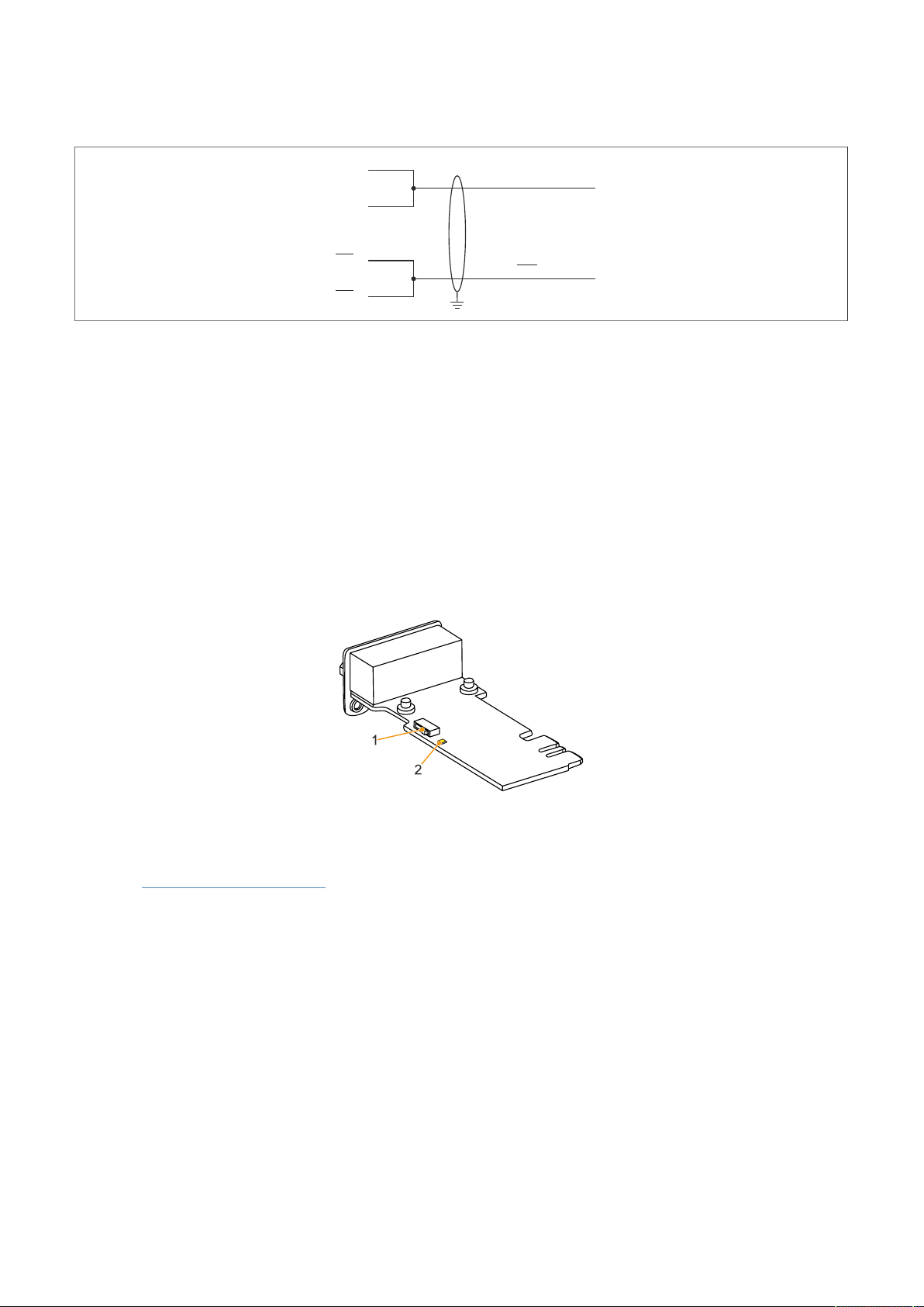
Technical data
DAT
A
DAT
A
TXD
RXD
TXD
RXD
9
4
6
1
4.2.4.2.3.4 Operation as RS485 interface
The pins of the RS422 default interface (1, 4, 6 and 9) must be used for operation. To do this, connect the
pins as shown.
Figure 1: RS232/RS422/RS485 interface - Operation in RS485 mode
The RTS line must be switched by the driver for each transmission or reception; switching back does not
take place automatically. This cannot be configured in Windows.
With long cable lengths, the voltage drop can result in greater potential differences between the bus devices, which can hinder communication. This can be improved by running the ground wire with the others.
The cable ends of an RS485 bus should be terminated (at least for longer cable lengths or higher transfer
rates). Passive termination can normally be used by connecting the signal lines via a 120 Ω resistor at each
of the two bus ends; see "Terminating resistor" for the IF card.
4.2.4.2.3.5 Terminating resistor
A terminating resistor for the serial interface is already integrated in the IF option. This can be switched on
or off with a switch (1); it is necessary to open the system unit for this. A switched-on terminating resistor
is indicated by a yellow LED (2) (see "Reading LED status indicators" on page 193).
4.2.4.2.4 Driver support
Drivers for approved operating systems are available for download in the Downloads section of the B&R
website (www.br-automation.com) (if required and not already included in the operating system).
Approved operating systems:
•
Automation Runtime
•
Linux for B&R
•
Windows 10
Automation PC 3200 User's manual V1.00 57
Page 58
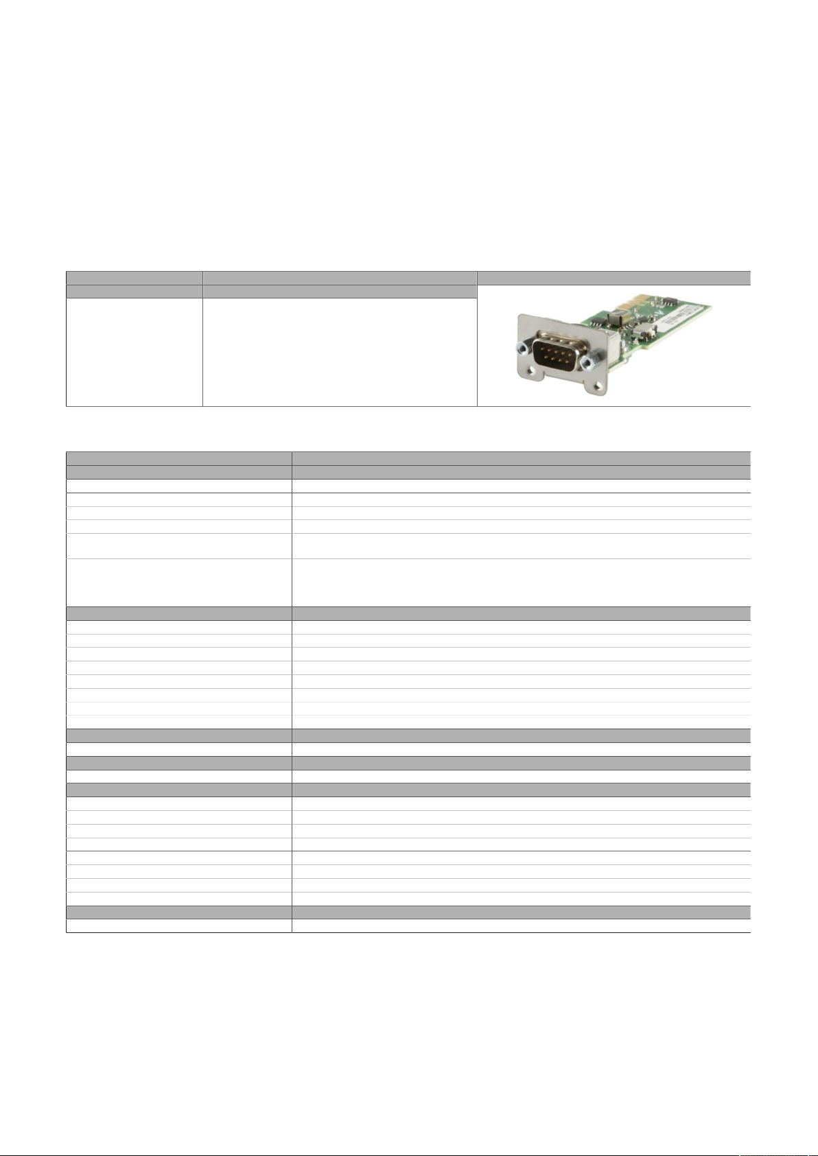
Technical data
4.2.4.3 5AC901.ICAN-01
4.2.4.3.1 General information
Interface option 5AC901.ICAN-01 is equipped with a CAN bus master interface.
•
1x CAN bus master interface (SJA1000)
•
Compatible with APC910/PPC900, APC3x00/PPC3x00 and APC4100
Simultaneous operation of 2 interface options with a legacy CAN interface in slots IF option 1 and IF option
2 is not possible.
4.2.4.3.2 Order data
Order number Short description Figure
5AC901.ICAN-01 Interface card - 1x CAN interface (SJA1000) - For APC910/
Interface options
PPC900 - For APC3x00/PPC3x00 - For APC4100
4.2.4.3.3 Technical data
Order number 5AC901.ICAN-01
General information
B&R ID code 0xD84C
Certifications
CE Yes
UKCA Yes
UL cULus E115267
HazLoc cULus HazLoc E180196
Interfaces
CAN
Quantity 1
Controller SJA1000
Variant DSUB, 9-pin, male, galvanically isolated
Transfer rate Max. 1 Mbit/s
Terminating resistor
Type Can be switched on and off with slide switch
Default setting Off
Electrical properties
Power consumption 0.5 W
Operating conditions
Pollution degree per EN 61131-2 Pollution degree 2
Ambient conditions
Temperature
Operation 0 to 60°C
Storage -20 to 60°C
Transport -20 to 60°C
Relative humidity
Operation 5 to 90%, non-condensing
Storage 5 to 95%, non-condensing
Transport 5 to 95%, non-condensing
Mechanical properties
Weight Approx. 33 g
1) For detailed information, see the temperature tables in the user's manual.
Industrial control equipment
Industrial control equipment
for hazardous locations
Class I, Division 2, Groups ABCD, T4
1)
58 Automation PC 3200 User's manual V1.00
Page 59
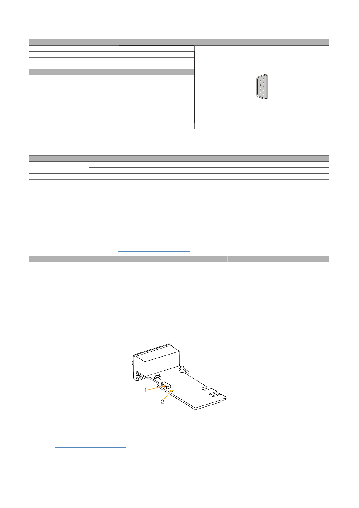
4.2.4.3.3.1 Pinout
5
1
9
6
Technical data
Variant DSUB, 9-pin, male
Galvanic isolation Yes
Transfer rate Max. 1 Mbit/s
Bus length Max. 1000 meters
Pin Pinout
1 NC
2 CAN LOW
3 GND
4 NC
5 NC
6 Reserved
7 CAN HIGH
8 NC
9 NC
1) Not connected
CAN bus
1)
4.2.4.3.3.2 I/O address and IRQ
Resource Default setting Function
IRQ IRQ10 Interrupt
1) Resource allocation is identical for the interface option 1 and 2 slots.
384h (address register) Defines the register number to be accessed.I/O address
385h (data register) Access to the register defined in the address register.
4.2.4.3.3.3 Cable data
For more detailed information about the transfer rate, bus length or cable requirements for the respective
interfaces/buses, see "Cable data" on page 188.
4.2.4.3.3.4 CAN driver settings
The baud rate can be set either with "predefined values" or via the "bit timing register".
For additional information, see www.br-automation.com in the B&R CAN driver user's manual.
Bit timing register 0 Bit timing register 1 Baud rate
00h 14h 1000 kbit/s
80h or 00h 1Ch 500 kbit/s
81h or 01h 1Ch 250 kbit/s
83h or 03h 1Ch 125 kbit/s
84h or 04h 1Ch 100 kbit/s
89h or 09h 1Ch 50 kbit/s
4.2.4.3.3.5 Terminating resistor
A terminating resistor for the CAN interface is already integrated in the IF option. This can be switched on
or off with a switch (1); it is necessary to open the system unit for this. A switched-on terminating resistor
is indicated by a yellow LED (2) (see "Reading LED status indicators" on page 193).
4.2.4.3.4 Drivers
Drivers for approved operating systems are available for download in the Downloads section of the B&R
website (www.br-automation.com) (if required and not already included in the operating system).
Approved operating systems:
Automation PC 3200 User's manual V1.00 59
Page 60

Technical data
•
Windows 10
•
Linux for B&R
•
Automation Runtime
60 Automation PC 3200 User's manual V1.00
Page 61
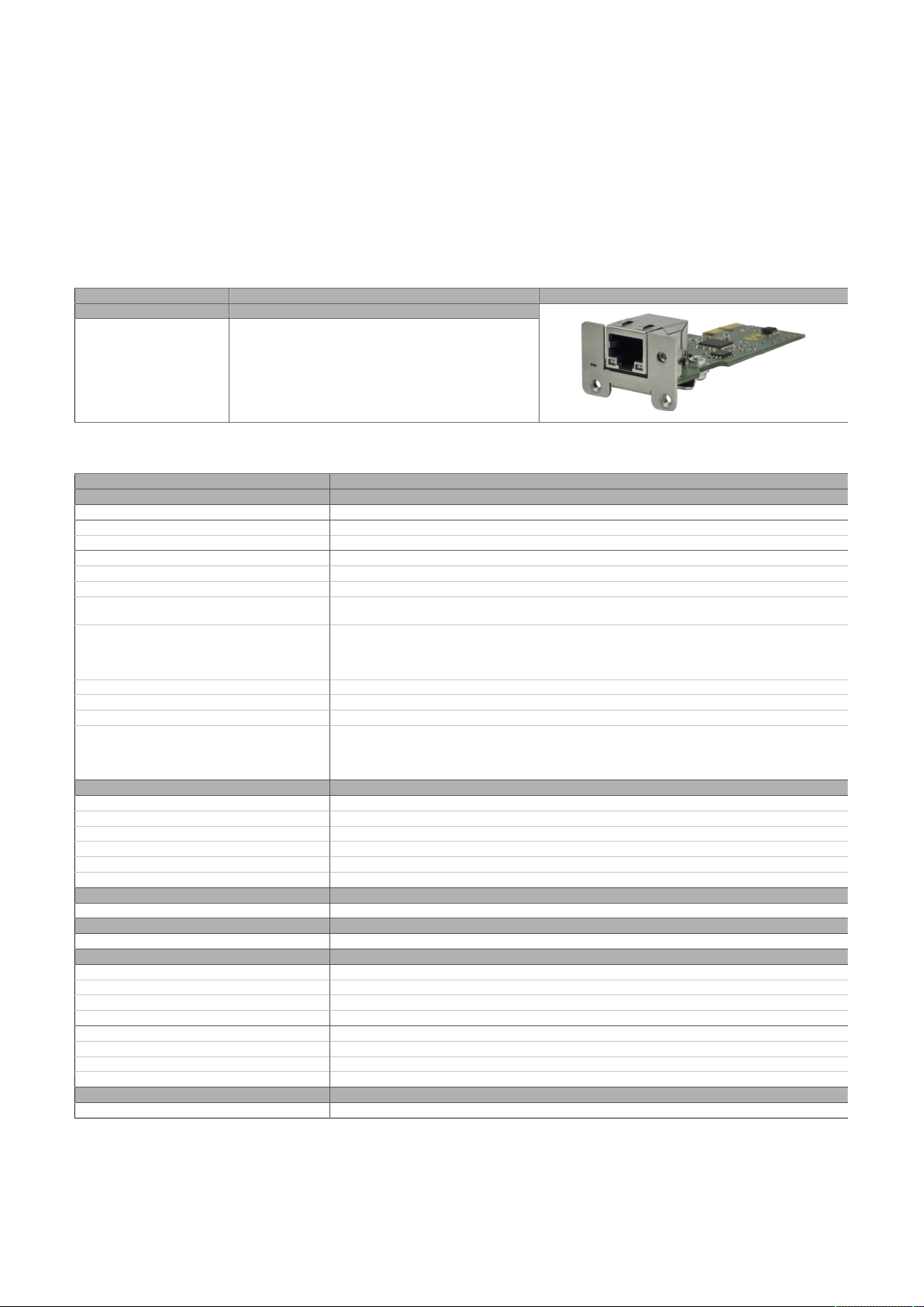
4.2.4.4 5AC901.IETH-00
4.2.4.4.1 General information
Interface option 5AC901.IETH-00 is equipped with a 10/100/1000BASE-T Ethernet interface.
•
1x Ethernet interface 10/100/1000BASE-T
•
Compatible with APC910/PPC900, APC3x00/PPC3x00 and APC4100
This interface option can only be operated in slot IF option 2.
4.2.4.4.2 Order data
Technical data
Order number Short description Figure
5AC901.IETH-00 Interface card - 1x ETH 10/100/1000 - For APC910/PPC900 -
Interface options
For APC3x00/PPC3x00 - For APC4100
4.2.4.4.3 Technical data
Order number 5AC901.IETH-00
General information
B&R ID code EC3C
Diagnostics
Data transfer Yes, using LED status indicator
Certifications
CE Yes
UKCA Yes
UL cULus E115267
DNV Temperature: B (0 to 55°C)
LR ENV3
KR Yes
ABS Yes
BV EC31B
Interfaces
Ethernet
Quantity 1
Controller Intel I210
Variant RJ45, shielded
Transfer rate 10/100/1000 Mbit/s
Line length Max. 100 m between two stations (segment length)
Electrical properties
Power consumption 1 W
Operating conditions
Pollution degree per EN 61131-2 Pollution degree 2
Ambient conditions
Temperature
Operation 0 to 55°C
Storage -20 to 60°C
Transport -20 to 60°C
Relative humidity
Operation 5 to 90%, non-condensing
Storage 5 to 95%, non-condensing
Transport 5 to 95%, non-condensing
Mechanical properties
Weight Approx. 35 g
1) Switching takes place automatically.
2) For detailed information, see the temperature tables in the user's manual.
Industrial control equipment
Humidity: B (up to 100%)
Vibration: A (0.7 g)
EMC: B (bridge and open deck)
Temperature: 5 - 55°C
Vibration: 0.7 g
EMC: Bridge and open deck
1)
2)
Automation PC 3200 User's manual V1.00 61
Page 62
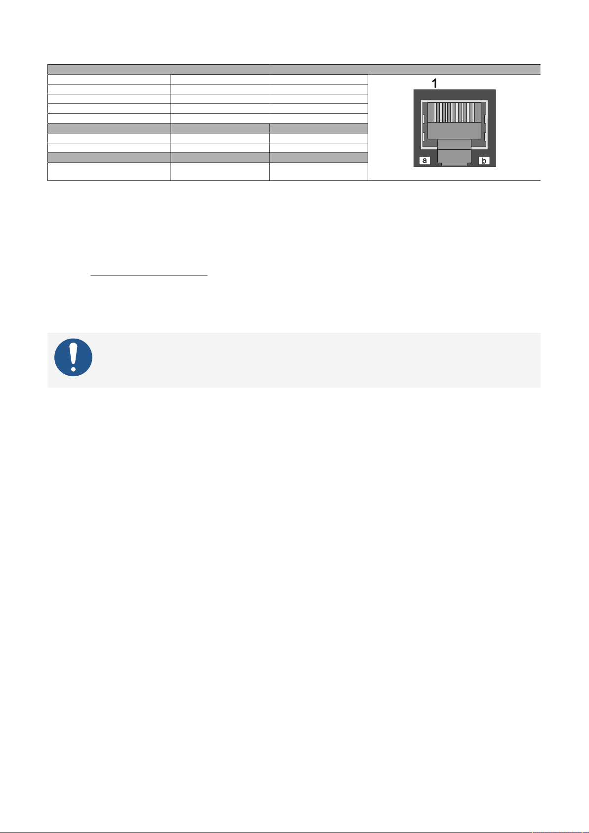
Technical data
4.2.4.4.3.1 Pinout
Variant RJ45, female
Controller Intel I210
Wiring S/STP (Cat 5e)
Transfer rate 10/100/1000 Mbit/s
Cable length Max. 100 m (min. Cat 5e)
LED "Speed" (a) On Off
Green 100 Mbit/s 10 Mbit/s
Orange (light) 1000 Mbit/s -
LED "Link" (b) On Active
Orange (light) Link (a connection to an
Ethernet network exists)
1) The interfaces, etc. available on the device or module have been numbered for the purpose of clear differentiation. This numbering may deviate
from the numbering used by the respective operating system, however.
2) Switching takes place automatically.
3) The 10 Mbit/s transfer rate / connection is only available if LED "Link" is active at the same time.
Ethernet interface (ETH1))
2)
3)
Blinking (data be-
ing transferred)
4.2.4.4.4 Driver support
Drivers for approved operating systems are available for download in the Downloads section of the B&R
website (www.br-automation.com) (if required and not already included in the operating system).
Approved operating systems:
•
Linux for B&R
•
Windows 10
Information:
Necessary drivers must be downloaded from the B&R website, not from manufacturer websites.
Wake-on-LAN (WoL) and PXE boot are not supported.
62 Automation PC 3200 User's manual V1.00
Page 63
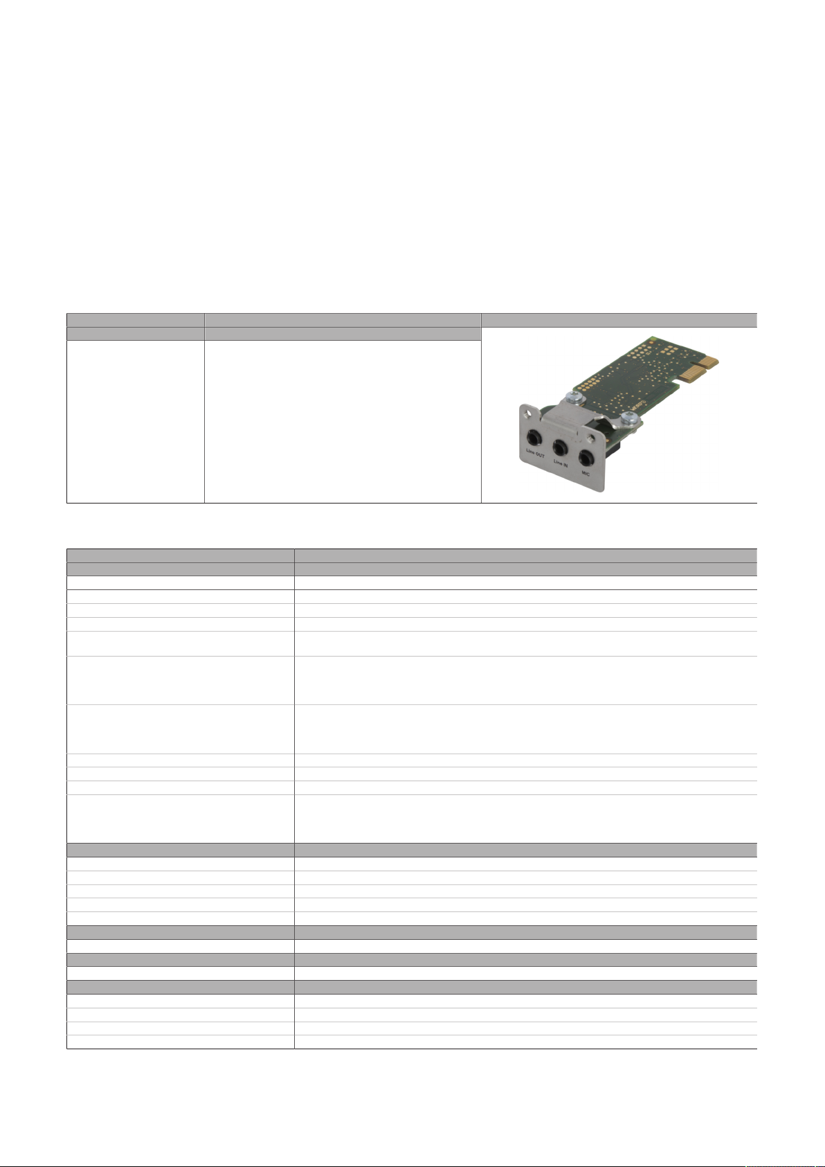
Technical data
4.2.4.5 5AC901.IHDA-00
4.2.4.5.1 General information
Interface option 5AC901.IHDA-00 is equipped with an HDA sound chip with externally accessible MIC, Line
IN and Line OUT channels.
•
1x MIC
•
1x Line IN
•
1x Line OUT
•
Compatible with APC910/PPC900, APC3x00/PPC3x00 and APC4100
This interface option can only be operated in slot IF option 1.
4.2.4.5.2 Order data
Order number Short description Figure
5AC901.IHDA-00 Interface card - 1x audio interface (1x MIC / 1x Line In / 1x
Interface options
OUT) - For APC910/PPC900 - For APC3x00/PPC3x00 - For
APC4100
4.2.4.5.3 Technical data
Order number 5AC901.IHDA-00
General information
B&R ID code 0xD84E
Certifications
CE Yes
UKCA Yes
UL cULus E115267
HazLoc cULus HazLoc E180196
DNV Temperature: B (0 to 55°C)
LR ENV3
KR Yes
ABS Yes
BV EC31B
Interfaces
Audio
Type HDA sound
Controller Realtek ALC 662
Inputs Microphone, Line In
Outputs Line Out
Electrical properties
Power consumption 0.4 W
Operating conditions
Pollution degree per EN 61131-2 Pollution degree 2
Ambient conditions
Temperature
Operation 0 to 55°C
Storage -20 to 60°C
Transport -20 to 60°C
Industrial control equipment
Industrial control equipment
for hazardous locations
Class I, Division 2, Groups ABCD, T3C
Humidity: B (up to 100%)
Vibration: A (0.7 g)
EMC: B (bridge and open deck)
Temperature: 5 - 55°C
Vibration: 0.7 g
EMC: Bridge and open deck
1)
Automation PC 3200 User's manual V1.00 63
Page 64
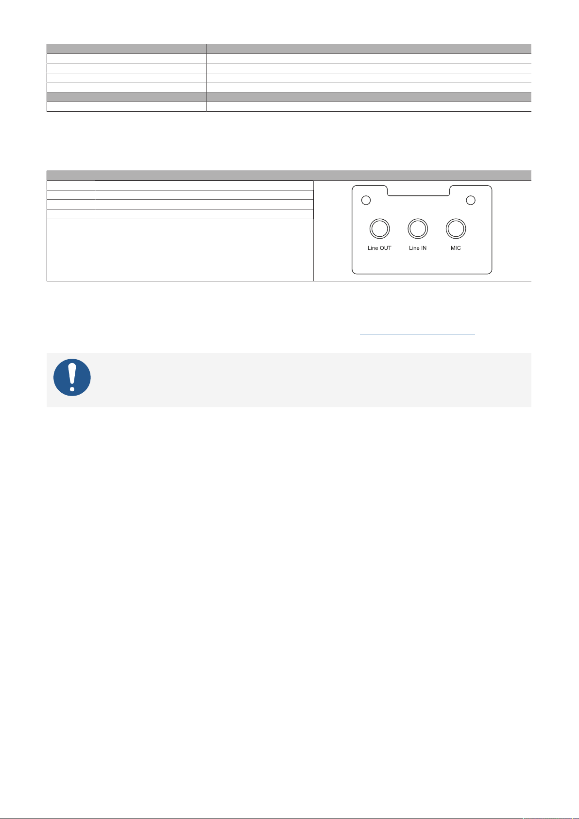
Technical data
Order number 5AC901.IHDA-00
Relative humidity
Operation 5 to 90%, non-condensing
Storage 5 to 95%, non-condensing
Transport 5 to 95%, non-condensing
Mechanical properties
Weight Approx. 21 g
1) For detailed information, see the temperature tables in the user's manual.
4.2.4.5.3.1 Pinout
All interfaces are designed as 3.5-mm jack connections (female).
Controller Realtek ALC 662
MIC Microphone input (mono)
Line IN Input (stereo)
Line OUT Output (stereo) for playback devices (e.g. amplifiers)
-
MIC, Line IN, Line OUT
4.2.4.5.4 Drivers
A special driver is necessary to operate the audio controller. Drivers for approved operating systems are
available for download in the Downloads section of the B&R website (www.br-automation.com) (if required
and not already included in the operating system).
Information:
Necessary drivers must be downloaded from the B&R website, not from manufacturer websites.
64 Automation PC 3200 User's manual V1.00
Page 65
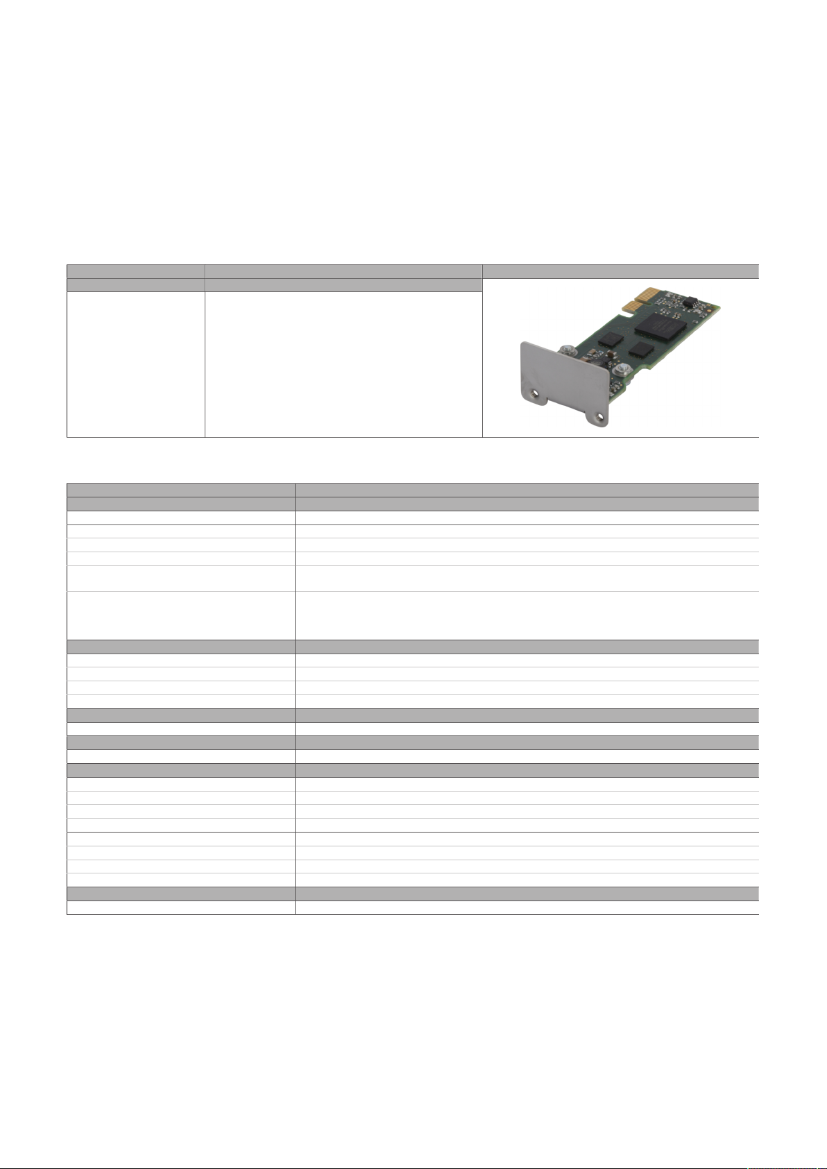
4.2.4.6 5AC901.ISRM-00
4.2.4.6.1 General information
Interface option 5AC901.ISRM-00 is equipped with 2 MB SRAM.
•
2 MB SRAM
•
Compatible with APC910/PPC900, APC3x00/PPC3x00 and APC4100
This interface option can only be operated in slot IF option 2.
4.2.4.6.2 Order data
Technical data
Order number Short description Figure
5AC901.ISRM-00 Interface card - 2 MB SRAM - For APC910/PPC900 - For
Interface options
APC3x00/PPC3x00 - For APC4100
4.2.4.6.3 Technical data
Order number 5AC901.ISRM-00
General information
B&R ID code 0xD850
Certifications
CE Yes
UKCA Yes
UL cULus E115267
HazLoc cULus HazLoc E180196
Controller
SRAM
Size 2 MB
Battery-backed Yes (backup battery of the system unit)
Remanent variables in power failure mode 256 kB (for e.g. Automation Runtime, see Automation Help)
Electrical properties
Power consumption 2 W
Operating conditions
Pollution degree per EN 61131-2 Pollution degree 2
Ambient conditions
Temperature
Operation 0 to 55°C
Storage -20 to 60°C
Transport -20 to 60°C
Relative humidity
Operation 5 to 90%, non-condensing
Storage 5 to 95%, non-condensing
Transport 5 to 95%, non-condensing
Mechanical properties
Weight Approx. 20 g
1) For detailed information, see the temperature tables in the user's manual.
Industrial control equipment
Industrial control equipment
for hazardous locations
Class I, Division 2, Groups ABCD, T4
1)
Automation PC 3200 User's manual V1.00 65
Page 66

Technical data
4.2.4.6.3.1 Drivers
Drivers for approved operating systems are available for download in the Downloads section of the B&R
website (www.br-automation.com) (if required and not already included in the operating system).
Approved operating systems:
•
Windows 10
•
Linux for B&R
•
Automation Runtime
66 Automation PC 3200 User's manual V1.00
Page 67
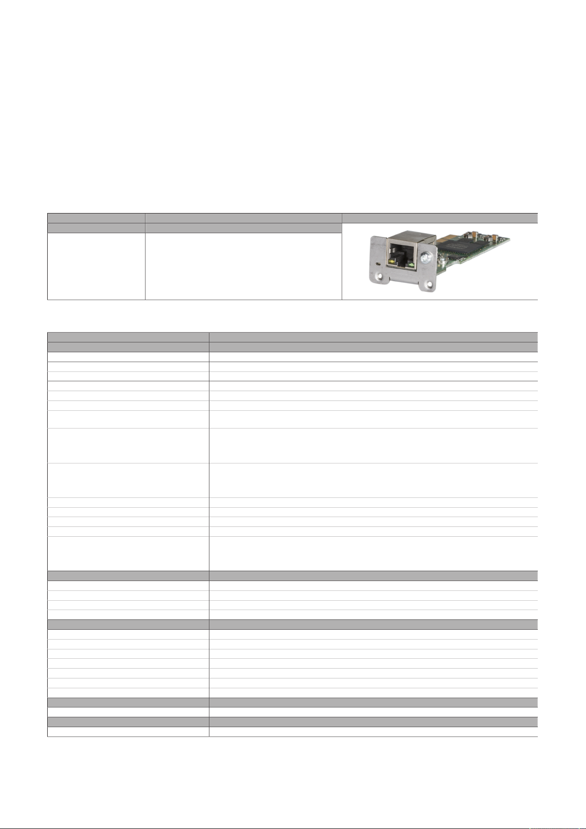
Technical data
4.2.4.7 5AC901.IPLK-00
4.2.4.7.1 General information
Interface option 5AC901.IPLK-00 is equipped with 1 POWERLINK interface and 2 MB SRAM.
•
1x POWERLINK interface managing or controlled node
•
2 MB SRAM
•
Compatible with APC910/PPC900, APC3x00/PPC3x00 and APC4100
This interface option can only be operated in the IF option 2 slot and is only supported by Automation
Runtime.
4.2.4.7.2 Order data
Order number Short description Figure
5AC901.IPLK-00 Interface card - 1x POWERLINK interface - 2 MB SRAM - For
Interface options
APC910/PPC900 - For APC3x00/PPC3x00 - For APC4100
4.2.4.7.3 Technical data
Order number 5AC901.IPLK-00
General information
B&R ID code 0xE025
Diagnostics
Data transfer Yes, using LED status indicator
Certifications
CE Yes
UKCA Yes
UL cULus E115267
HazLoc cULus HazLoc E180196
DNV Temperature: B (0 to 55°C)
CCS Yes
LR ENV3
KR Yes
ABS Yes
BV EC31B
Controller
SRAM
Size 2 MB
Battery-backed Yes (backup battery of the system unit)
Remanent variables in power failure mode 256 kB (for e.g. Automation Runtime, see Automation Help)
Interfaces
POWERLINK
Quantity 1
Type Type 4
Variant RJ45, shielded
Transfer rate 100 Mbit/s
Transfer 100BASE-TX
Line length Max. 100 m between two stations (segment length)
Electrical properties
Power consumption 1.5 W
Operating conditions
Pollution degree per EN 61131-2 Pollution degree 2
Industrial control equipment
Industrial control equipment
for hazardous locations
Class I, Division 2, Groups ABCD, T4
Humidity: B (up to 100%)
Vibration: A (0.7 g)
EMC: B (bridge and open deck)
Temperature: 5 - 55°C
Vibration: 0.7 g
EMC: Bridge and open deck
1)
Automation PC 3200 User's manual V1.00 67
Page 68
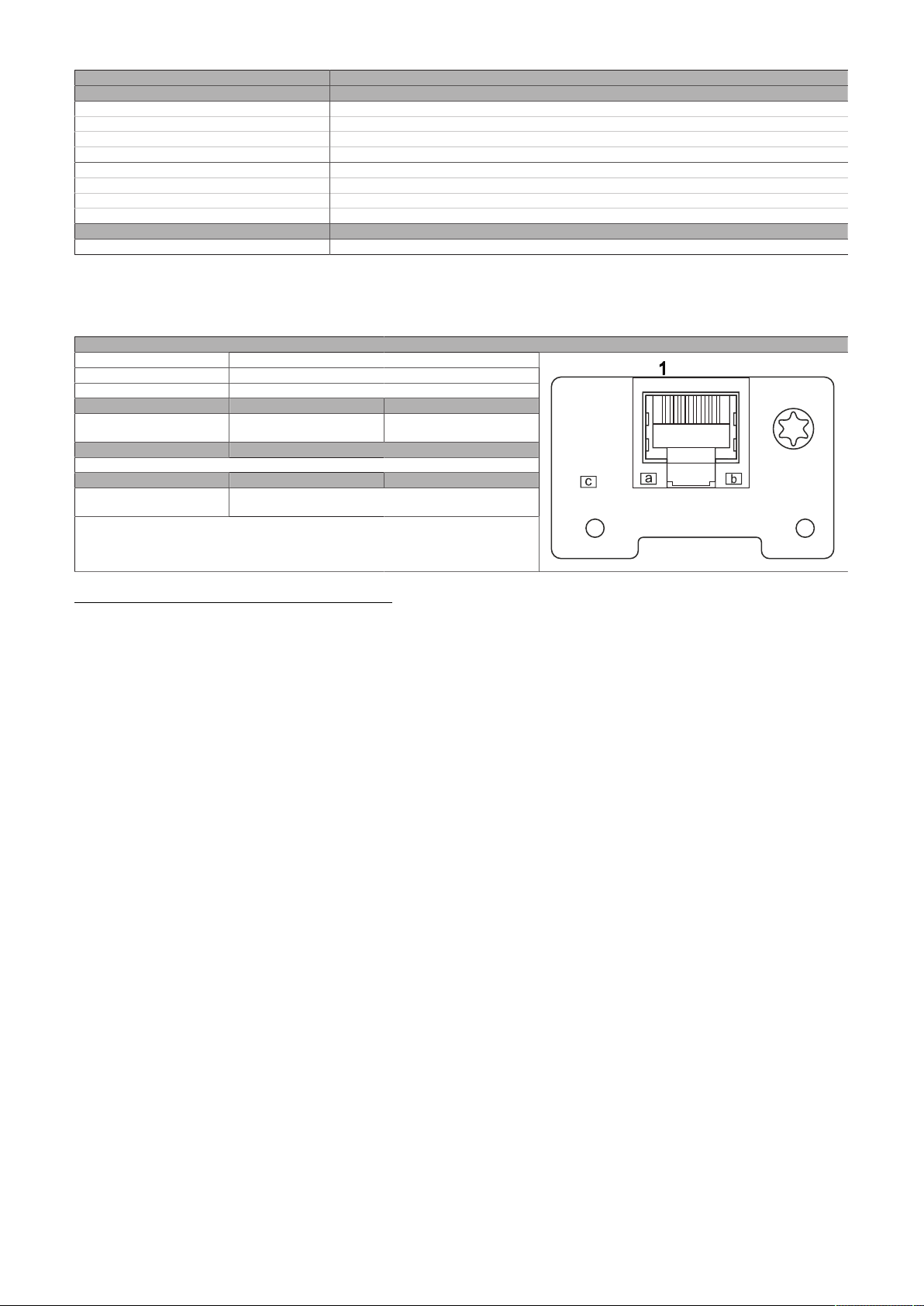
Technical data
Order number 5AC901.IPLK-00
Ambient conditions
Temperature
Operation 0 to 55°C
Storage -20 to 60°C
Transport -20 to 60°C
Relative humidity
Operation 5 to 90%, non-condensing
Storage 5 to 95%, non-condensing
Transport 5 to 95%, non-condensing
Mechanical properties
Weight Approx. 35 g
1) For additional information, see Automation Help (Communication - POWERLINK - General information - Hardware - IF / LS).
2) For detailed information, see the temperature tables in the user's manual.
2)
4.2.4.7.3.1 Pinout
Variant RJ45, female
Wiring S/STP (Cat 5e)
Cable length Max. 100 m (min. Cat 5e)
LED "Link" (a) On Active
Orange (light) Link (a connection to a POW-
(b) -
LED "Status/Error" (c) On Off
Green/Red
ERLINK network exists)
-
POWERLINK status see "LED "S/
E" (status/error LED)" on page 190
-
POWERLINK
Blinking (data be-
ing transferred)
POWERLINK commissioning and operation
For a description of the operating modes, status and node numbers of the POWERLINK interface(s), see
"LED "S/E" (status/error LED)" on page 190.
4.2.4.7.3.2 Driver support and firmware update
The driver is part of the Automation Runtime and the firmware is part of Automation Studio. The module
is automatically brought up to this level.
To update the firmware contained in Automation Studio, a hardware upgrade must be performed (see
Project management / Workspace / Upgrades in Automation Help).
68 Automation PC 3200 User's manual V1.00
Page 69
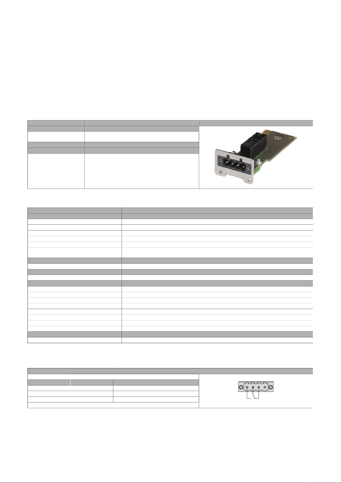
Technical data
1 2
3
4
NC
NO
4.2.4.8 5AC901.IRDY-00
4.2.4.8.1 General information
Ready relay 5AC901.IRDY-00 is switched as soon as the B&R industrial PC has started up and all internal
supply voltages are applied. It is possible to connect additional devices to the ready relay; they will also be
switched on when the B&R industrial PC starts up.
•
1 normally closed contact, 1 normally open contact
•
Compatible with APC910/PPC900, APC3x00/PPC3x00 and APC4100
Terminal block 0TB2104.8000 is not included in delivery and must be ordered separately.
4.2.4.8.2 Order data
Order number Short description Figure
5AC901.IRDY-00 Interface card - Ready relay - For APC910/PPC900 - For
0TB2104.8000 Connector 24 VDC - 4-pin female - Screw clamp terminal
Interface options
APC3x00/PPC3x00 - For APC4100
Required accessories
Terminal blocks
block 2.5 mm²
4.2.4.8.3 Technical data
Order number 5AC901.IRDY-00
General information
B&R ID code 0xD84F
Ready relay Normally open contact and normally closed contact, max. 30 VDC, max. 2 A
Certifications
CE Yes
UKCA Yes
UL cULus E115267
Electrical properties
Power consumption 0.2 W
Operating conditions
Pollution degree per EN 61131-2 Pollution degree 2
Ambient conditions
Temperature
Operation 0 to 60°C
Storage -20 to 60°C
Transport -20 to 60°C
Relative humidity
Operation 5 to 90%, non-condensing
Storage 5 to 95%, non-condensing
Transport 5 to 95%, non-condensing
Mechanical properties
Weight Approx. 30 g
1) For detailed information, see the temperature tables in the user's manual.
Industrial control equipment
1)
4.2.4.8.3.1 Pinout
Variant 4-pin, male
Pin Pinout Description
1 NO Normally open contact
2 COM Changeover contact
3 NC Normally closed contact
4 NC
1) Not connected.
Automation PC 3200 User's manual V1.00 69
1)
Ready relay
Page 70
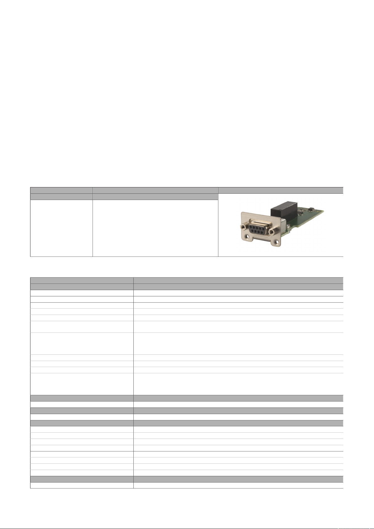
Technical data
4.2.4.9 5AC901.ISIO-00
4.2.4.9.1 General information
The ready relay function of IF option 5AC901.ISIO-00 can be controlled using the MTCX. Corresponding
commands must be issued by the MTCX in order to switch the ready relay.
In addition to the ready relay function, the reset and power button as well as the power LED of a B&R PC
can be routed externally.
•
Connections for the reset button and power buttons on the PC
•
Connection for LED "Power" on the PC
•
1 normally closed contact, 1 normally open contact of the ready relay
•
Control of the ready relay functions using MTCX commands
•
Compatible with APC910/PPC900, APC3x00/PPC3x00 and APC4100
Unlike IF option 5AC901.IRDY-00, ready relay 5AC901.ISIO-00 is not automatically switched on or off if the
power supply to the PC is switched on or off.
The maximum cable length for connecting the reset button, power button and LED "Power" is 2 m.
4.2.4.9.2 Order data
Order number Short description Figure
5AC901.ISIO-00 Interface card - System I/O - For APC910/PPC900 - For
Interface options
APC3x00/PPC3x00 - For APC4100
4.2.4.9.3 Technical data
Order number 5AC901.ISIO-00
General information
B&R ID code 0xE674
Ready relay Normally open contact and normally closed contact, max. 30 VDC, max. 1 A
Certifications
CE Yes
UKCA Yes
UL cULus E115267
DNV Temperature: B (0 to 55°C)
CCS Yes
LR ENV3
ABS Yes
BV EC31B
Electrical properties
Power consumption 0.5 W
Operating conditions
Pollution degree per EN 61131-2 Pollution degree 2
Ambient conditions
Temperature
Operation 0 to 60°C
Storage -20 to 60°C
Transport -20 to 60°C
Relative humidity
Operation 5 to 90%, non-condensing
Storage 5 to 95%, non-condensing
Transport 5 to 95%, non-condensing
Mechanical properties
Weight Approx. 30 g
1) For detailed information, see the temperature tables in the user's manual.
Industrial control equipment
Humidity: B (up to 100%)
Vibration: A (0.7 g)
EMC: B (bridge and open deck)
Temperature: 5 - 55°C
Vibration: 0.7 g
EMC: Bridge and open deck
1)
70 Automation PC 3200 User's manual V1.00
Page 71
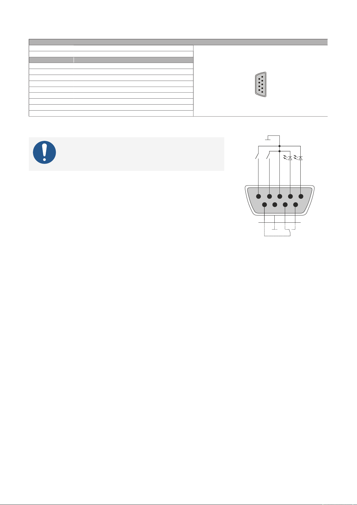
4.2.4.9.3.1 Pinout
1
5
6
9
GND
GND
NC NO
Reset
Red LED
Green LED
5
1
9 6
COM
Power
Technical data
Variant DSUB, 9-pin, female
Cable length Max. 2 meters
Pin Pinout
1 Output LED ("Power") - Green
2 Output LED ("Power") - Red
3 GND
4 Input - Power button
5 Input - Reset button
6 Relay, normally open contact
7 Relay, normally closed contact
8 GND
9 COM relay, changeover contact
Ready relay
4.2.4.9.3.2 Connection example
Information:
Series resistors for the LEDs are already installed on
the interface option.
The LED outputs are dimensioned for a typical LED current of 3.5 mA.
Automation PC 3200 User's manual V1.00 71
Page 72
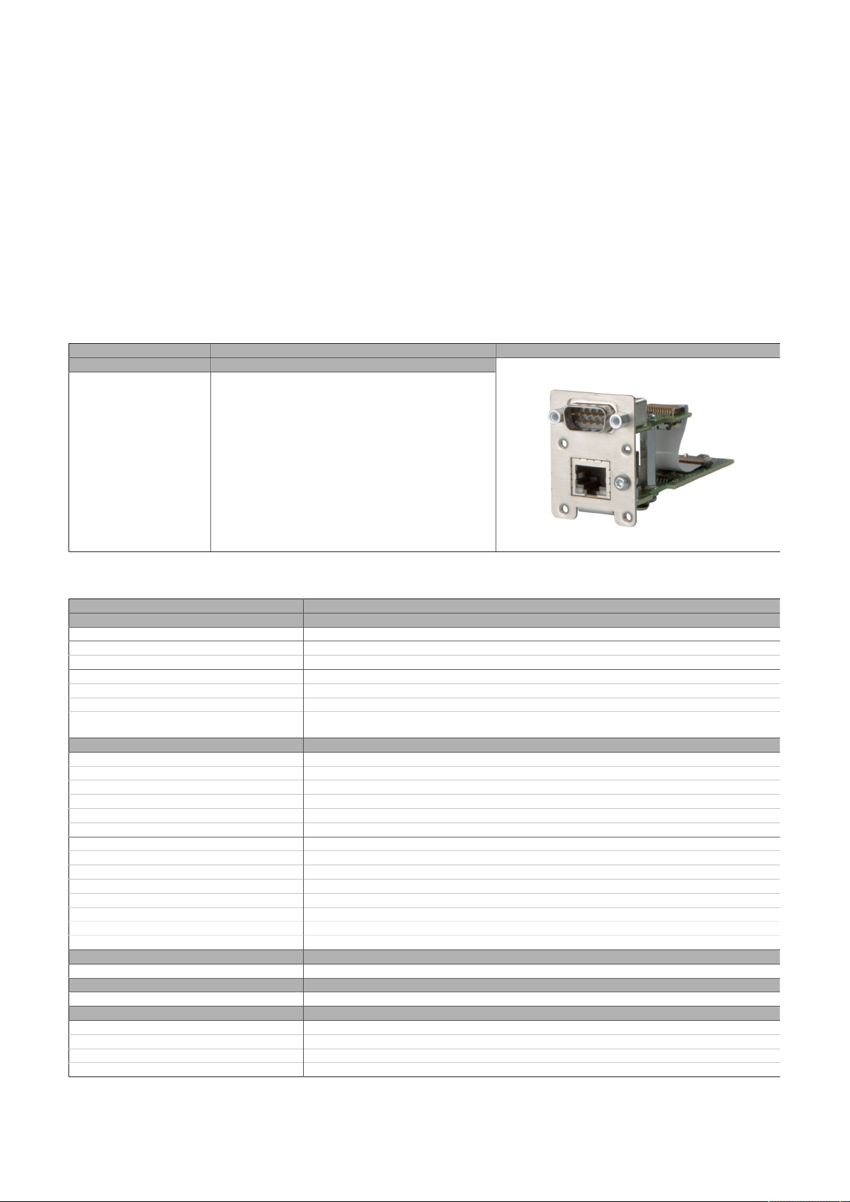
Technical data
4.2.4.10 5ACCIF02.CANE-000
4.2.4.10.1 General information
Interface option 5ACCIF02.CANE-000 has a 10/100/1000BASE-T Ethernet interface and a CAN bus master
interface.
•
1x Ethernet interface 10/100/1000BASE-T
•
1x CAN bus master interface (SJA1000)
•
Compatible with APC3x00/PPC3x00
This interface option can only be operated in slot IF option 2 and additionally uses slot IF option 2 add-on.
Simultaneous operation of 2 interface options with a legacy CAN interface in slots IF option 1 and IF option
2 is not possible.
4.2.4.10.2 Order data
Order number Short description Figure
5ACCIF02.CANE-000 Interface card - 1x CAN interface (SJA1000) - 1x ETH
Interface options
10/100/1000 - For APC3x00/PPC3x00
4.2.4.10.3 Technical data
Order number 5ACCIF02.CANE-000
General information
B&R ID code 0xF171
Diagnostics
Data transfer Yes, using LED status indicator
Certifications
CE Yes
UKCA Yes
UL cULus E115267
Interfaces
Ethernet
Quantity 1
Controller Intel I210
Variant RJ45, shielded
Transfer rate 10/100/1000 Mbit/s
Line length Max. 100 m between two stations (segment length)
CAN
Quantity 1
Controller SJA1000
Variant DSUB, 9-pin, male, galvanically isolated
Transfer rate Max. 1 Mbit/s
Terminating resistor
Type Can be switched on and off with slide switch
Default setting Off
Electrical properties
Power consumption 1.5 W
Operating conditions
Pollution degree per EN 61131-2 Pollution degree 2
Ambient conditions
Temperature
Operation 0 to 55°C
Storage -20 to 60°C
Transport -20 to 60°C
Industrial control equipment
1)
2)
72 Automation PC 3200 User's manual V1.00
Page 73
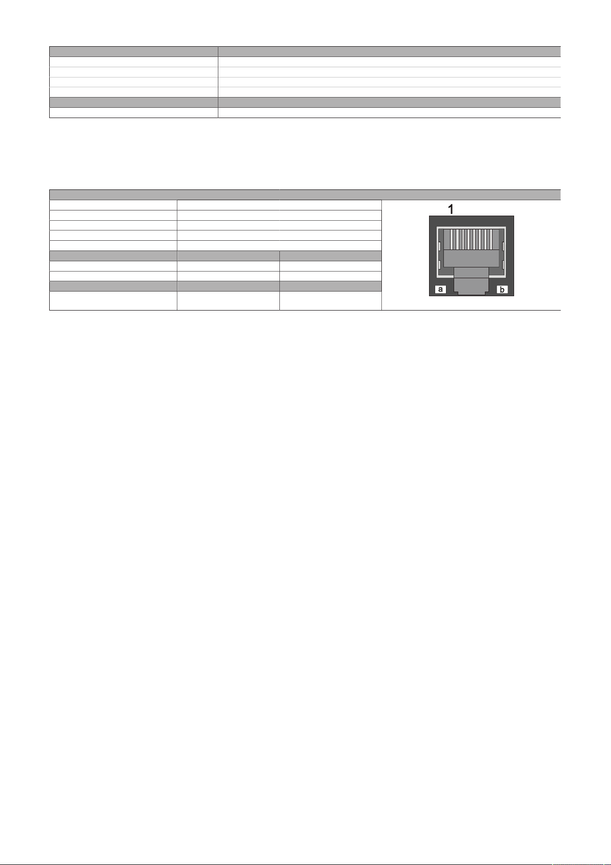
Technical data
Order number 5ACCIF02.CANE-000
Relative humidity
Operation 5 to 90%, non-condensing
Storage 5 to 95%, non-condensing
Transport 5 to 95%, non-condensing
Mechanical properties
Weight Approx. 60 g
1) Switching takes place automatically.
2) For detailed information, see the temperature tables in the user's manual.
4.2.4.10.3.1 ETH - Pinout
The Ethernet interface is available in the IF option 2 slot.
Variant RJ45, female
Controller Intel I210
Wiring S/STP (Cat 5e)
Transfer rate 10/100/1000 Mbit/s
Cable length Max. 100 m (min. Cat 5e)
LED "Speed" (a) On Off
Green 100 Mbit/s 10 Mbit/s
Orange (light) 1000 Mbit/s -
LED "Link" (b) On Active
Orange (light) Link (a connection to an
Ethernet network exists)
1) The interfaces, etc. available on the device or module have been numbered for the purpose of clear differentiation. This numbering may deviate
from the numbering used by the respective operating system, however.
2) Switching takes place automatically.
3) The 10 Mbit/s transfer rate / connection is only available if LED "Link" is active at the same time.
Ethernet interface (ETH1))
2)
3)
Blinking (data be-
ing transferred)
Automation PC 3200 User's manual V1.00 73
Page 74
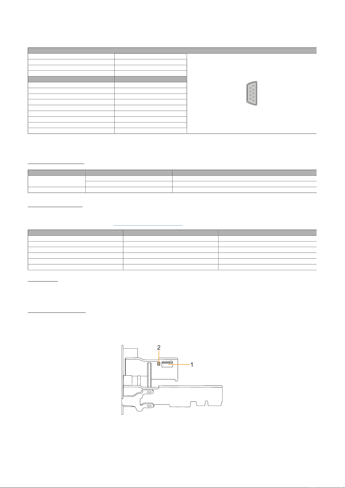
Technical data
5
1
9
6
4.2.4.10.3.2 CAN - Pinout
The CAN interface is available in the IF option 2 add-on slot.
1)
Variant DSUB, 9-pin, male
Galvanic isolation Yes
Transfer rate Max. 1 Mbit/s
Bus length Max. 1000 meters
Pin Pinout
1 NC
2 CAN LOW
3 GND
4 NC
5 NC
6 Reserved
7 CAN HIGH
8 NC
9 NC
1) The interfaces, etc. available on the device or module have been numbered for the purpose of clear differentiation. This numbering may deviate
from the numbering used by the respective operating system, however.
2) Not connected
CAN bus
2)
I/O address and IRQ
Resource Default setting Function
IRQ IRQ10 Interrupt
384h (address register) Defines the register number to be accessed.I/O address
385h (data register) Access to the register defined in the address register.
CAN driver settings
The baud rate can be set either with "predefined values" or via the "bit timing register".
For additional information, see www.br-automation.com in the B&R CAN driver user's manual.
Bit timing register 0 Bit timing register 1 Baud rate
00h 14h 1000 kbit/s
80h or 00h 1Ch 500 kbit/s
81h or 01h 1Ch 250 kbit/s
83h or 03h 1Ch 125 kbit/s
84h or 04h 1Ch 100 kbit/s
89h or 09h 1Ch 50 kbit/s
Cable data
For more detailed information about the transfer rate, bus length or cable requirements for the respective
interfaces/buses, see "Cable data" on page 188.
Terminating resistor
A terminating resistor for the CAN interface is already integrated in the IF option. This can be switched on
or off with a switch (1); it is necessary to open the system unit for this. A switched-on terminating resistor
is indicated by a yellow LED (2) (see "Reading LED status indicators" on page 193).
74 Automation PC 3200 User's manual V1.00
Page 75

Technical data
4.2.4.10.4 Driver support
Drivers for approved operating systems are available for download in the Downloads section of the B&R
website (www.br-automation.com) (if required and not already included in the operating system).
Approved operating systems:
•
Linux for B&R
•
Windows 10
Information:
Necessary drivers must be downloaded from the B&R website, not from manufacturer websites.
Wake-on-LAN (WoL) and PXE boot are not supported.
Automation PC 3200 User's manual V1.00 75
Page 76
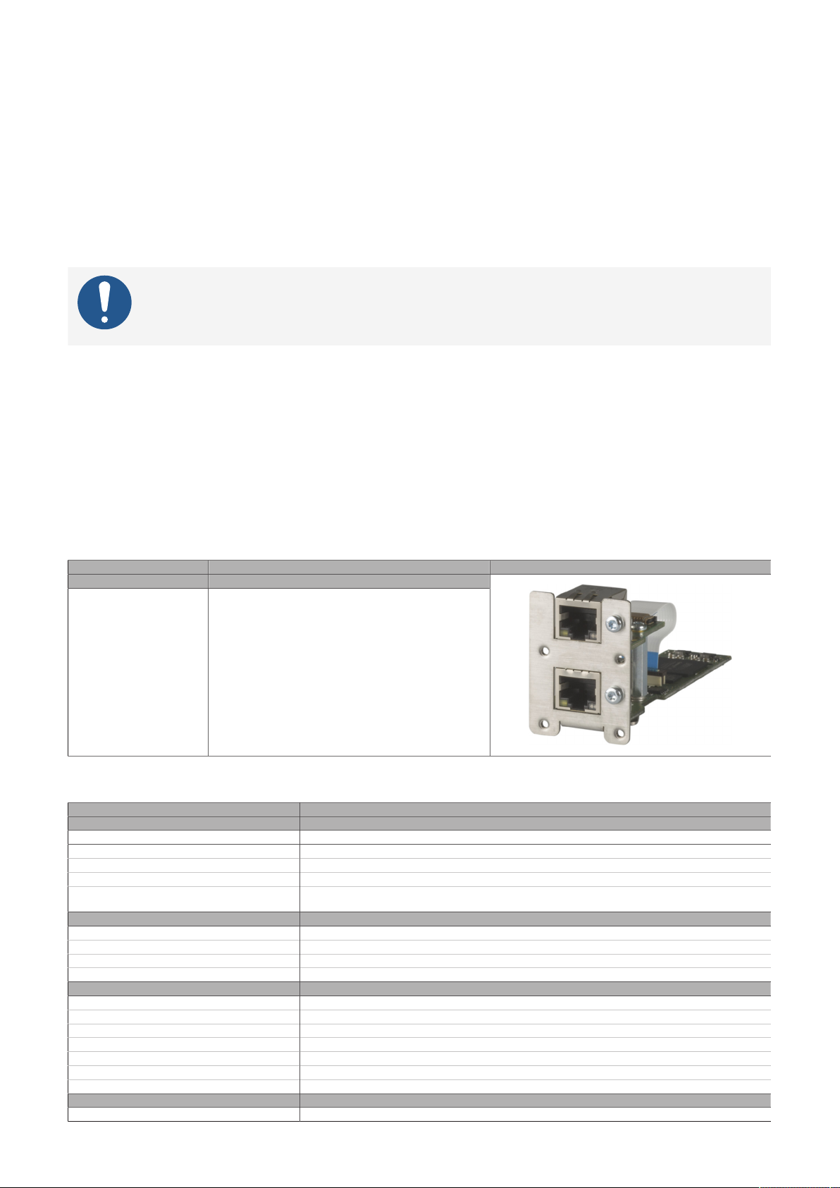
Technical data
4.2.4.11 5ACCIF02.FPLK-000
4.2.4.11.1 General information
Interface option 5ACCIF02.FPLK-000 is equipped with 2 female RJ45 connectors connected to an integrated
POWERLINK hub. 2 MB SRAM is also installed.
With the integrated 2-port hub, a simple tree structure, daisy chain wiring or optional ring redundancy can
be easily implemented without additional effort.
With poll-response chaining (PRC), the IF option offers a solution for the highest demands on response time
and the shortest cycle times. When combined with the B&R control system, poll-response chaining provides
ideal performance, particularly for central control tasks.
Information:
Ring redundancy and simultaneous poll-response chaining operation is not possible with
this IF option.
•
1x POWERLINK interface for real-time communication
•
2 MB SRAM
•
Integrated hub for economical wiring
•
Configurable ring redundancy
•
Poll-response chaining
•
Compatible with APC3x00/PPC3x00
This interface option can only be operated in slot IF option 2, additionally uses slot IF option 2 add-on and
is only supported by Automation Runtime.
4.2.4.11.2 Order data
Order number Short description Figure
5ACCIF02.FPLK-000 Interface card - 1x POWERLINK interface - 2 MB SRAM - In-
Interface options
tegrated 2-port hub - Ring redundancy - POWERLINK managing or controlled mode - PRC function - For APC3x00/
PPC3x00
4.2.4.11.3 Technical data
Order number 5ACCIF02.FPLK-000
General information
B&R ID code 0xF10E
Certifications
CE Yes
UKCA Yes
UL cULus E115267
Controller
SRAM
Size 2 MB
Battery-backed Yes (backup battery of the system unit)
Remanent variables in power failure mode 256 kB (for e.g. Automation Runtime, see Automation Help)
Interfaces
POWERLINK
Quantity 1 (integrated 2-port hub)
Type Type 4, redundant
Variant RJ45, shielded
Transfer rate 100 Mbit/s
Transfer 100BASE-TX
Line length Max. 100 m between two stations (segment length)
Electrical properties
Power consumption 2 W
76 Automation PC 3200 User's manual V1.00
Industrial control equipment
1)
Page 77
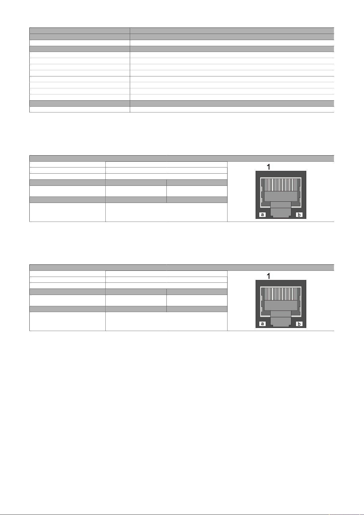
Order number 5ACCIF02.FPLK-000
Operating conditions
Pollution degree per EN 61131-2 Pollution degree 2
Ambient conditions
Temperature
Operation 0 to 55°C
Storage -20 to 60°C
Transport -20 to 60°C
Relative humidity
Operation 5 to 90%, non-condensing
Storage 5 to 95%, non-condensing
Transport 5 to 95%, non-condensing
Mechanical properties
Weight Approx. 55 g
1) For additional information, see Automation Help (Communication - POWERLINK - General information - Hardware - IF / LS).
2) For detailed information, see the temperature tables in the user's manual.
2)
4.2.4.11.3.1 POWERLINK 1 interface - Pinout
The POWERLINK 1 interface is available in the IF option 2 slot.
Variant RJ45, female
Wiring S/STP (Cat 5e)
Cable length Max. 100 m (min. Cat 5e)
LED "Link" (a) On Active
Orange (light) Link (a connection to a POW-
ERLINK network exists)
LED "Status" (b) On Off
Green/Red POWERLINK status
see "LED "S/E" (status/error LED)" on page 190
POWERLINK 1 - IF1
Blinking (data be-
1)
ing transferred)
Technical data
1) The interfaces, etc. available on the device or module have been numbered for the purpose of clear differentiation. This numbering may deviate
from the numbering used by the respective operating system, however.
4.2.4.11.3.2 POWERLINK 2 interface - Pinout
The POWERLINK 2 interface is available in the IF option 2 add-on slot.
Variant RJ45, female
Wiring S/STP (Cat 5e)
Cable length Max. 100 m (min. Cat 5e)
LED "Link" (a) On Active
Orange (light) Link (a connection to a POW-
ERLINK network exists)
LED "Status" (b) On Off
Green/Red POWERLINK status
see "LED "S/E" (status/error LED)" on page 190
1) The interfaces, etc. available on the device or module have been numbered for the purpose of clear differentiation. This numbering may deviate
from the numbering used by the respective operating system, however.
POWERLINK 2 - IF2
Blinking (data be-
1)
ing transferred)
4.2.4.11.3.3 POWERLINK commissioning and operation
For a description of the operating modes, status and node numbers of the POWERLINK interface(s), see
"LED "S/E" (status/error LED)" on page 190.
4.2.4.11.4 Driver support and firmware update
The driver is part of the Automation Runtime and the firmware is part of Automation Studio. The module
is automatically brought up to this level.
To update the firmware contained in Automation Studio, a hardware upgrade must be performed (see
Project management / Workspace / Upgrades in Automation Help).
Automation PC 3200 User's manual V1.00 77
Page 78
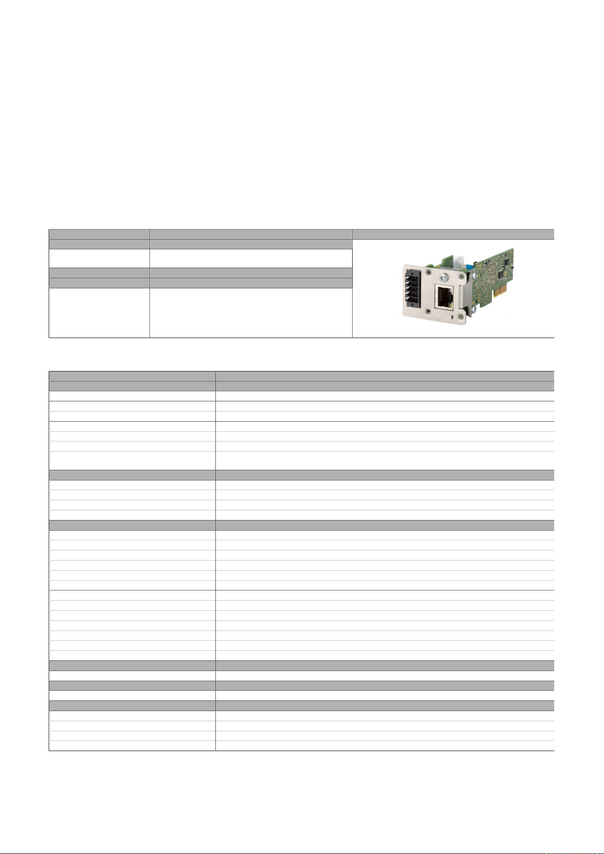
Technical data
4.2.4.12 5ACCIF02.FPLS-000
4.2.4.12.1 General information
Interface option 5ACCIF02.FPLS-000 is equipped with a POWERLINK and RS232 interface. In addition, 2 MB
SRAM is installed.
•
1x POWERLINK interface managing or controlled node
•
1x RS232 interface
•
2 MB SRAM
•
Compatible with APC3x00/PPC3x00
This interface option can only be operated in slot IF option 2 and additionally uses slot IF option 2 add-on.
4.2.4.12.2 Order data
Order number Short description Figure
5ACCIF02.FPLS-000 Interface card - 2 MB SRAM - 1x RS232 interface - 1x POWER-
0TB1210.3100 Connector 300 VDC - 10-pin female - Cage clamp terminal
Interface options
LINK interface - For APC3x00/PPC3x00
Optional accessories
Terminal blocks
block - Protected against vibration by the screw flange
4.2.4.12.3 Technical data
Order number 5ACCIF02.FPLS-000
General information
B&R ID code 0xF2E2
Diagnostics
Data transfer Yes, using LED "Status/Error"
Certifications
CE Yes
UKCA Yes
UL cULus E115267
Controller
SRAM
Size 2 MB
Battery-backed Yes (backup battery of the system unit)
Remanent variables in power failure mode 256 kB (for e.g. Automation Runtime, see Automation Help)
Interfaces
COM
Quantity 1
Type RS232, modem supported, not galvanically isolated
Variant 10-pin, male
UART 16550-compatible, 16-byte FIFO buffer
Max. baud rate 115 kbit/s
POWERLINK
Quantity 1
Type Type 4
Variant RJ45, shielded
Transfer rate 100 Mbit/s
Transfer 100BASE-TX
Line length Max. 100 m between two stations (segment length)
Electrical properties
Power consumption 1.75 W
Operating conditions
Pollution degree per EN 61131-2 Pollution degree 2
Ambient conditions
Temperature
Operation 0 to 55°C
Storage -20 to 60°C
Transport -20 to 60°C
Industrial control equipment
1)
2)
78 Automation PC 3200 User's manual V1.00
Page 79
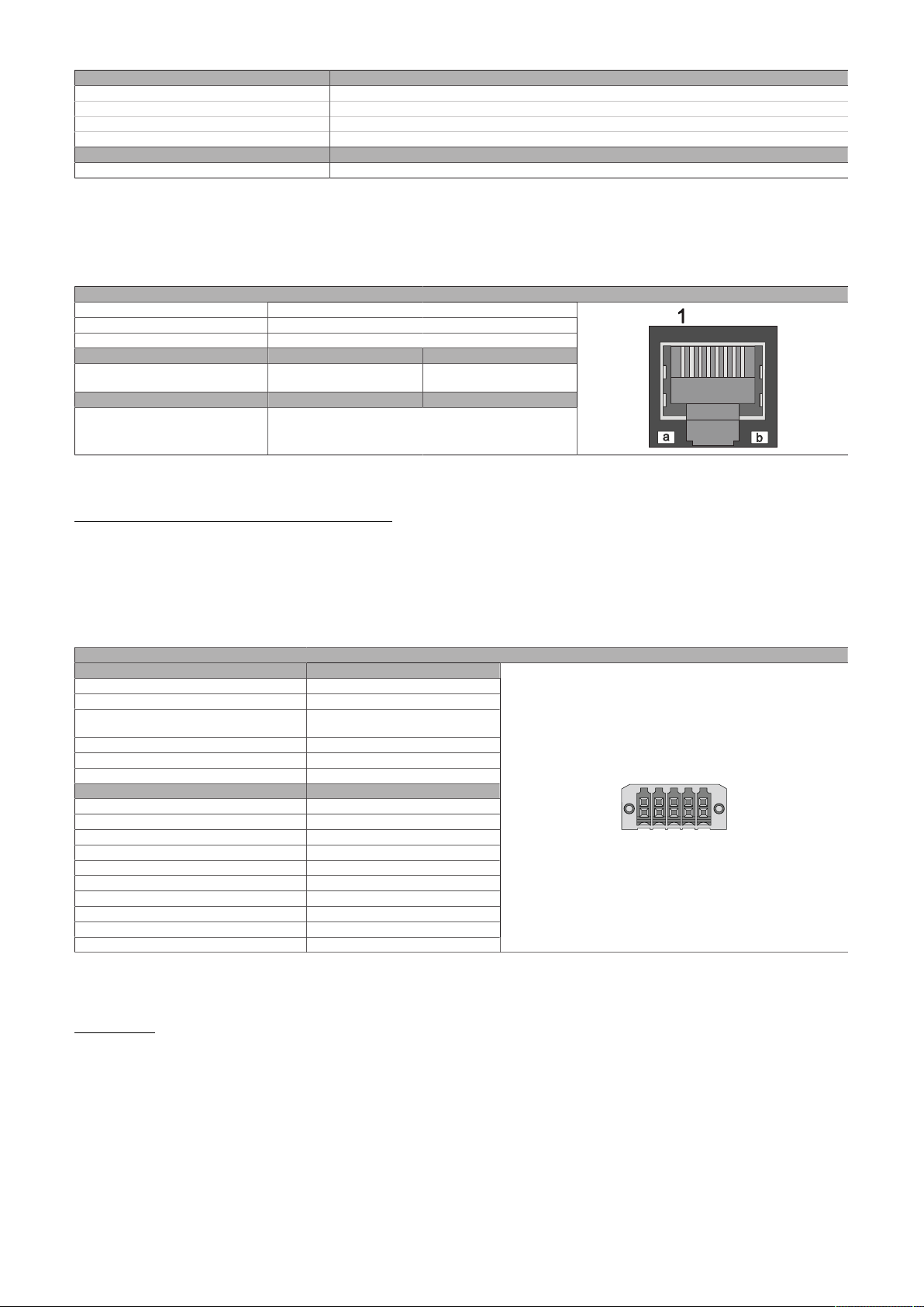
Technical data
1 3 5 7
2 4 6 8 10
9
Order number 5ACCIF02.FPLS-000
Relative humidity
Operation 5 to 90%, non-condensing
Storage 5 to 95%, non-condensing
Transport 5 to 95%, non-condensing
Mechanical properties
Weight Approx. 55 g
1) For additional information, see Automation Help (Communication - POWERLINK - General information - Hardware - IF / LS).
2) For detailed information, see the temperature tables in the user's manual.
4.2.4.12.3.1 POWERLINK interface - Pinout
The POWERLINK interface is available in the IF option 2 slot.
Variant RJ45, female
POWERLINK
Wiring S/STP (Cat 5e)
Cable length Max. 100 m (min. Cat 5e)
LED "Link" (a) On Active
Orange (light) Link (a connection to a POW-
ERLINK network exists)
LED "Status" (b) On Off
Green/Red POWERLINK status
"LED "S/E" (status/error LED)" on page 190
1) The interfaces, etc. available on the device or module have been numbered for the purpose of clear differentiation. This numbering may deviate
from the numbering used by the respective operating system, however.
1)
Blinking (data be-
ing transferred)
POWERLINK commissioning and operation
For a description of the operating modes, status and node numbers of the POWERLINK interface(s), see
"LED "S/E" (status/error LED)" on page 190.
4.2.4.12.3.2 Serial interface COM B - Pinout
Serial interface COM B is available in the IF option 2 add-on slot.
Serial interface COM B
RS232
Variant 10-pin, male
Type RS232, modem supported
UART 16550-compatible,
16-byte FIFO buffer
Galvanic isolation No
Transfer rate Max. 115 kbit/s
Bus length Max. 15 m
Pin Pinout
1 DCD
2 DSR
3 RXD
4 RTS
5 TXD
6 CTS
7 DTR
8 RI
9 GND
10 Shield
1) The interfaces, etc. available on the device or module have been numbered for the purpose of clear differentiation. This numbering may deviate
from the numbering used by the respective operating system, however.
2) This interface (if available) is automatically enabled in BIOS as COM B with default addresses I/O:2F8h and IRQ:3.
1)2)
Cable data
For more detailed information about the transfer rate, bus length or cable requirements for the respective
interfaces/buses, see "Cable data" on page 188.
Automation PC 3200 User's manual V1.00 79
Page 80

Technical data
4.2.4.12.4 Shielding
For the interfaces on the 10-pin female connector, the shield of the interfaces can be connected to pin Shield
(pin 2) of the female connector.
4.2.4.12.5 Driver support and firmware update
Drivers for approved operating systems are available for download in the Downloads section of the B&R
website (www.br-automation.com) (if required and not already included in the operating system).
Approved operating systems:
•
Automation Runtime
•
Linux for B&R
•
Windows 10
Automation Runtime / B&R Hypervisor (RTOS)
The driver is part of the Automation Runtime and the firmware is part of Automation Studio. The module
is automatically brought up to this level.
To update the firmware contained in Automation Studio, a hardware upgrade must be performed (see
Project management / Workspace / Upgrades in Automation Help).
All interfaces of the interface option are supported in Automation Runtime / B&R Hypervisor.
General-purpose operating system (GPOS)
If this interface option is used with a GPOS, only operation of the serial interfaces(s) is supported and the
firmware update function cannot be used.
80 Automation PC 3200 User's manual V1.00
Page 81
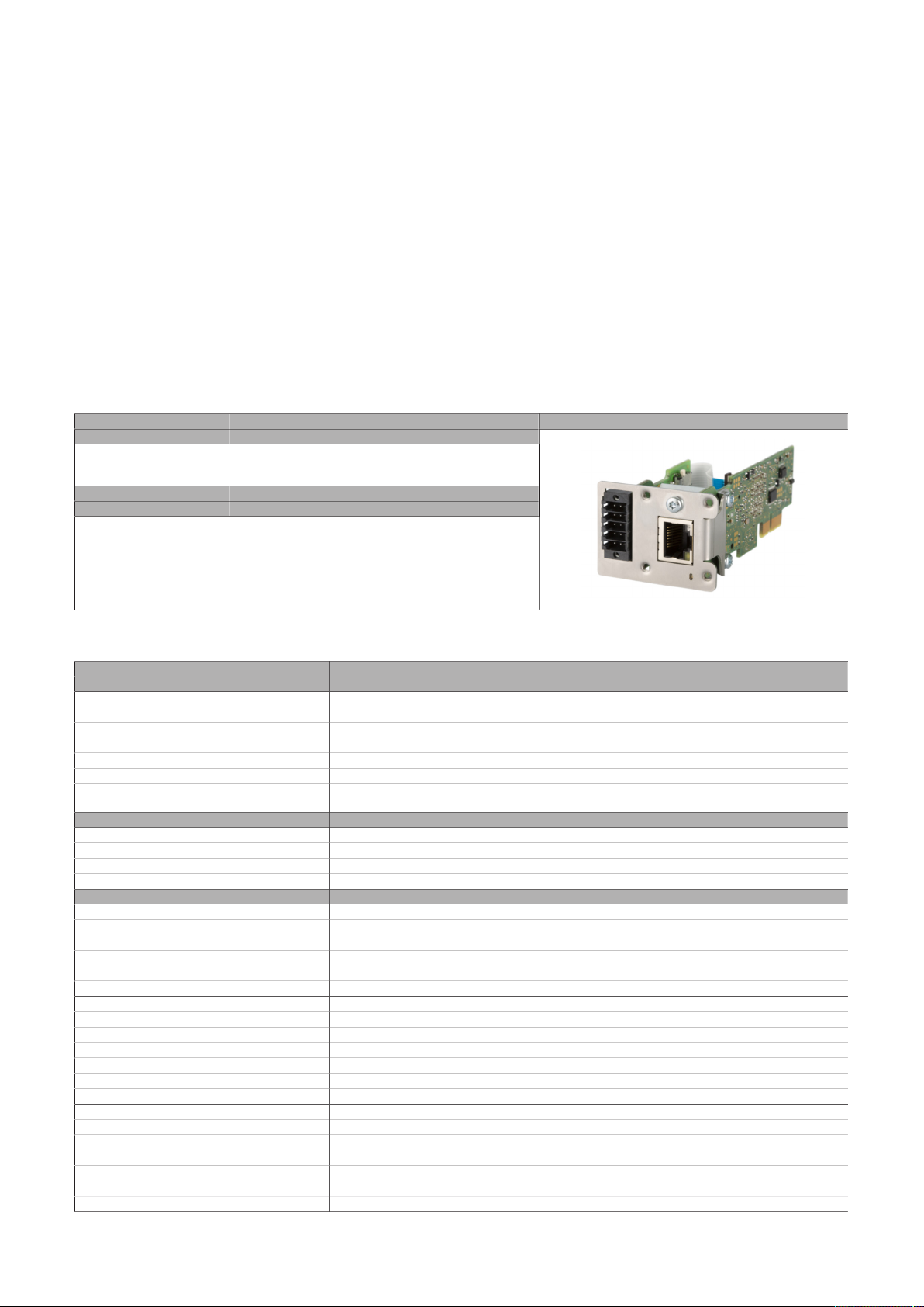
Technical data
4.2.4.13 5ACCIF02.FPSC-000
4.2.4.13.1 General information
Interface option 5ACCIF02.FPSC-000 is equipped with a POWERLINK, RS232 and CAN bus master as well as
an X2X Link master interface. In addition, 2 MB SRAM is installed.
•
1x POWERLINK interface managing or controlled node
•
1x CAN bus master interface
•
1x X2X Link master interface
•
1x RS232 interface
•
2 MB SRAM
•
Compatible with APC3x00/PPC3x00
This interface option can only be operated in slot IF option 2, additionally uses slot IF option 2 add-on and
is only supported by Automation Runtime.
4.2.4.13.2 Order data
Order number Short description Figure
5ACCIF02.FPSC-000 Interface card - 2 MB SRAM - 1x RS232 interface - 1x CAN in-
0TB1210.3100 Connector 300 VDC - 10-pin female - Cage clamp terminal
Interface options
terface - 1x POWERLINK interface - 1x X2X - For APC3x00/
PPC3x00
Optional accessories
Terminal blocks
block - Protected against vibration by the screw flange
4.2.4.13.3 Technical data
Order number 5ACCIF02.FPSC-000
General information
B&R ID code 0xF2E3
Diagnostics
Data transfer Yes, using LED "Status/Error"
Certifications
CE Yes
UKCA Yes
UL cULus E115267
Controller
SRAM
Size 2 MB
Battery-backed Yes (backup battery of the system unit)
Remanent variables in power failure mode 256 kB (for e.g. Automation Runtime, see Automation Help)
Interfaces
COM
Quantity 1
Type RS232, modem not supported, not galvanically isolated
Variant 10-pin, male
UART 16550-compatible, 16-byte FIFO buffer
Max. baud rate 115 kbit/s
POWERLINK
Quantity 1
Type Type 4
Variant RJ45, shielded
Transfer rate 100 Mbit/s
Transfer 100BASE-TX
Line length Max. 100 m between two stations (segment length)
CAN
Quantity 1
Variant 10-pin, male, galvanically isolated
Transfer rate Max. 1 Mbit/s
Terminating resistor
Type Can be switched on and off with slide switch
Default setting Off
Industrial control equipment
1)
Automation PC 3200 User's manual V1.00 81
Page 82
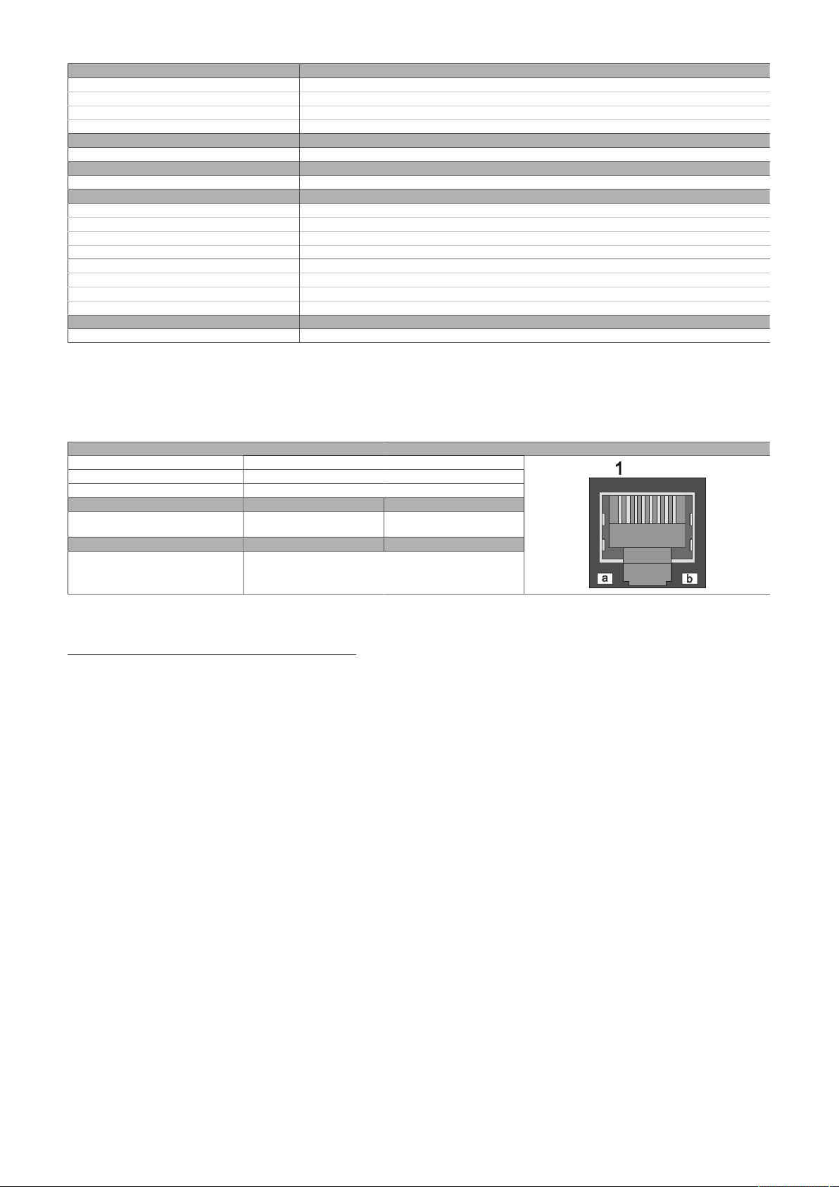
Technical data
Order number 5ACCIF02.FPSC-000
X2X
Type X2X Link master
Quantity 1
Variant 10-pin, male, galvanically isolated
Electrical properties
Power consumption 2 W
Operating conditions
Pollution degree per EN 61131-2 Pollution degree 2
Ambient conditions
Temperature
Operation 0 to 55°C
Storage -20 to 60°C
Transport -20 to 60°C
Relative humidity
Operation 5 to 90%, non-condensing
Storage 5 to 95%, non-condensing
Transport 5 to 95%, non-condensing
Mechanical properties
Weight Approx. 55 g
1) For additional information, see Automation Help (Communication - POWERLINK - General information - Hardware - IF / LS).
2) For detailed information, see the temperature tables in the user's manual.
2)
4.2.4.13.3.1 POWERLINK interface - Pinout
The POWERLINK interface is available in the IF option 2 slot.
Variant RJ45, female
POWERLINK
Wiring S/STP (Cat 5e)
Cable length Max. 100 m (min. Cat 5e)
LED "Link" (a) On Active
Orange (light) Link (a connection to a POW-
ERLINK network exists)
LED "Status" (b) On Off
Green/Red POWERLINK status
"LED "S/E" (status/error LED)" on page 190
1)
Blinking (data be-
ing transferred)
1) The interfaces, etc. available on the device or module have been numbered for the purpose of clear differentiation. This numbering may deviate
from the numbering used by the respective operating system, however.
POWERLINK commissioning and operation
For a description of the operating modes, status and node numbers of the POWERLINK interface(s), see
"LED "S/E" (status/error LED)" on page 190.
82 Automation PC 3200 User's manual V1.00
Page 83
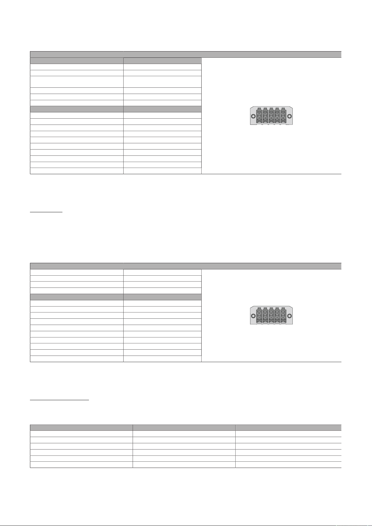
Technical data
1 3 5 7
2 4 6 8 10
9
1 3 5 7
2 4 6 8 10
9
4.2.4.13.3.2 Serial interface COM - Pinout
Serial interface COM is available in the IF option 2 add-on slot.
Serial interface COM
RS232
Variant 10-pin, male
Type RS232, not modem supported
UART 16550-compatible,
16-byte FIFO buffer
Galvanic isolation No
Transfer rate Max. 115 kbit/s
Bus length Max. 15 m
Pin Pinout
1 2 Shield
3 -
4 -
5 -
6 -
7 8 COM GND
9 RXD
10 TXD
1) The interfaces, etc. available on the device or module have been numbered for the purpose of clear differentiation. This numbering may deviate
from the numbering used by the respective operating system, however.
2) This interface can only be used in Automation Runtime and is displayed as IF5 in Automation Studio / Automation Runtime. It is not a "PC interface"
and therefore not displayed in BIOS.
1)2)
Cable data
For more detailed information about the transfer rate, bus length or cable requirements for the respective
interfaces/buses, see "Cable data" on page 188.
4.2.4.13.3.3 CAN bus interface - Pinout
The CAN bus interface is available in the IF option 2 add-on slot.
Variant 10-pin, male
CAN bus
Galvanic isolation Yes
Transfer rate Max. 1 Mbit/s
Bus length Max. 1000 m
Pin Pinout
1 2 Shield
3 -
4 -
5 CAN H
6 CAN L
7 CAN GND
8 9 -
10 -
1) The interfaces, etc. available on the device or module have been numbered for the purpose of clear differentiation. This numbering may deviate
from the numbering used by the respective operating system, however.
2) This interface can only be used in Automation Runtime and is displayed as IF3 in Automation Studio / Automation Runtime. It is not a "PC interface"
and therefore not displayed in BIOS.
1)2)
CAN driver settings
The baud rate can be set either with "predefined values" or via the "bit timing register".
For additional information, see Automation Help.
Automation PC 3200 User's manual V1.00 83
Bit timing register 0 Bit timing register 1 Baud rate
00h 14h 1000 kbit/s
80h or 00h 1Ch 500 kbit/s
81h or 01h 1Ch 250 kbit/s
83h or 03h 1Ch 125 kbit/s
84h or 04h 1Ch 100 kbit/s
89h or 09h 1Ch 50 kbit/s
Page 84
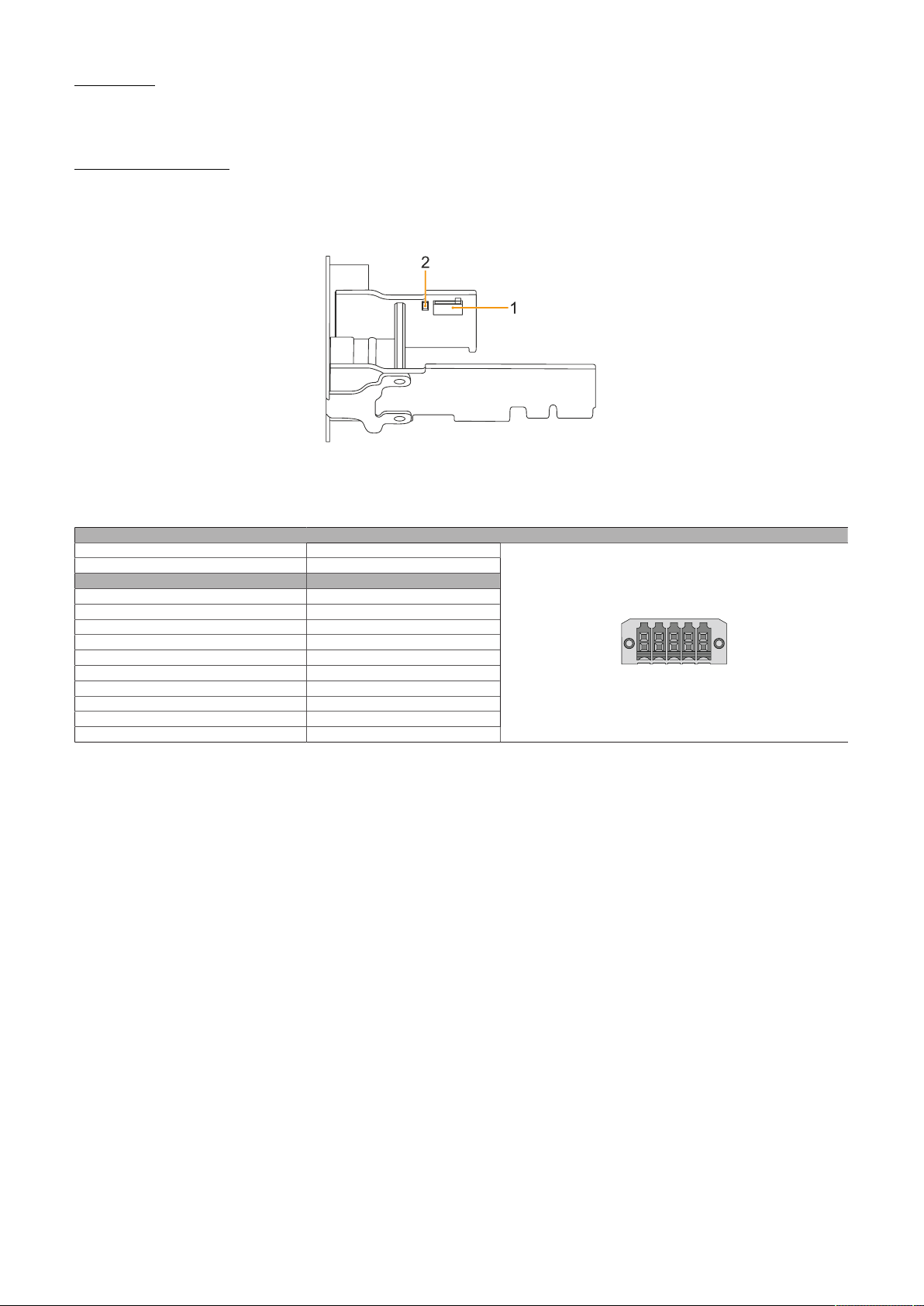
Technical data
1 3 5 7
2 4 6 8 10
9
Cable data
For more detailed information about the transfer rate, bus length or cable requirements for the respective
interfaces/buses, see "Cable data" on page 188.
Terminating resistor
A terminating resistor for the CAN interface is already integrated in the IF option. This can be switched on
or off with a switch (1); it is necessary to open the system unit for this. A switched-on terminating resistor
is indicated by a yellow LED (2) (see "Reading LED status indicators" on page 193).
4.2.4.13.3.4 X2X Link master interface - Pinout
The X2X Link master interface is available in the IF option 2 add-on slot.
Variant 10-pin, male
X2X Link master
Galvanic isolation Yes
Pin Pinout
1 X2X
2 Shield
3 X2X\
4 X2X⊥
5 -
6 -
7 8 9 -
10 -
1) The interfaces, etc. available on the device or module have been numbered for the purpose of clear differentiation. This numbering may deviate
from the numbering used by the respective operating system, however.
2) This interface can only be used in Automation Runtime and is displayed as IF2 in Automation Studio / Automation Runtime. It is not a "PC interface"
and therefore not displayed in BIOS.
1)2)
4.2.4.13.4 Shielding
For the interfaces on the 10-pin female connector, the shield of the interfaces can be connected to pin Shield
(pin 2) of the female connector.
4.2.4.13.5 Driver support and firmware update
The driver is part of the Automation Runtime and the firmware is part of Automation Studio. The module
is automatically brought up to this level.
To update the firmware contained in Automation Studio, a hardware upgrade must be performed (see
Project management / Workspace / Upgrades in Automation Help).
84 Automation PC 3200 User's manual V1.00
Page 85
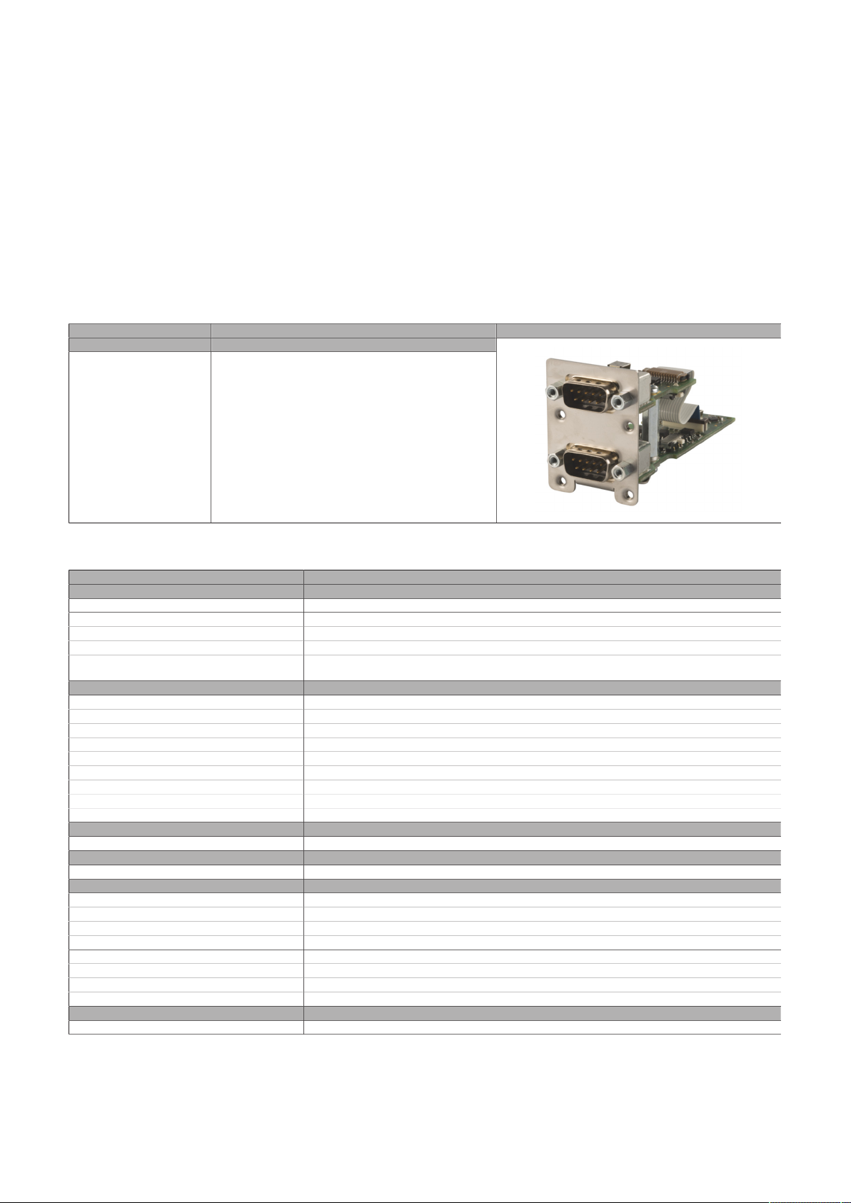
Technical data
4.2.4.14 5ACCIF02.ISS0-000
4.2.4.14.1 General information
Interface option 5ACCIF02.ISS0-000 is equipped with two RS232/RS422/RS485 interfaces. The operating
mode (RS232/RS422/RS485) is selected automatically depending on the electrical connection.
•
2x RS232/RS422/RS485 interfaces
•
Compatible with APC3x00/PPC3x00
This interface option can only be operated in slot IF option 2 and additionally uses slot IF option 2 add-on.
Simultaneous operation of this interface option with interface option 5AC901.I232-00 or 5AC901.I485-00
in slot IF option 1 is not possible.
4.2.4.14.2 Order data
Order number Short description Figure
5ACCIF02.ISS0-000 Interface card - 2x RS232/RS422/RS485 interface - For
Interface options
APC3x00/PPC3x00
4.2.4.14.3 Technical data
Order number 5ACCIF02.ISS0-000
General information
B&R ID code 0xF725
Certifications
CE Yes
UKCA Yes
UL cULus E115267
Interfaces
COM
Quantity 2
Type RS232/RS422/RS485, galvanically isolated
Variant DSUB, 9-pin, male
UART 16550-compatible, 16-byte FIFO buffer
Max. baud rate 115 kbit/s
Terminating resistor
Type Possible to switch each on/off via slide switch
Default setting Each off
Electrical properties
Power consumption 1.5 W
Operating conditions
Pollution degree per EN 61131-2 Pollution degree 2
Ambient conditions
Temperature
Operation 0 to 60°C
Storage -20 to 60°C
Transport -20 to 60°C
Relative humidity
Operation 5 to 90%, non-condensing
Storage 5 to 95%, non-condensing
Transport 5 to 95%, non-condensing
Mechanical properties
Weight Approx. 65 g
1) For detailed information, see the temperature tables in the user's manual.
Industrial control equipment
1)
Automation PC 3200 User's manual V1.00 85
Page 86
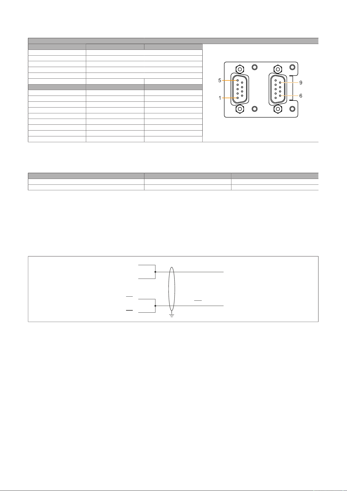
Technical data
COM A COM B
DAT
A
DAT
A
TXD
RXD
TXD
RXD
9
4
6
1
4.2.4.14.3.1 Pinout
Variant DSUB, 9-pin, male
Type RS232, not modem supported
UART 16550-compatible, 16-byte FIFO buffer
Galvanic isolation Yes
Transfer rate Max. 115 kbit/s
Bus length Max. 15 m Max. 1200 m
Pin RS232 - Pinout
1 NC
2 RXD NC
3 TXD NC
4 NC TXD
5 GND GND
6 NC RXD\
7 RTS NC
8 CTS NC
9 NC RXD
1) Pins marked "NC" are not permitted to be used or connected in the respective operating mode.
2) Not connected.
RS232 RS422/485
2)
Serial interfaces COM A and COM B
1)
RS422 - Pinout
TXD\
1)
4.2.4.14.3.2 I/O address and IRQ
Slot (interface) I/O address IRQ
IF option 2 add-on (COM A) 3F8h - 3FFh 4
IF option 2 (COM B) 2F8h - 2FFh 3
4.2.4.14.3.3 Cable data
For more detailed information about the transfer rate, bus length or cable requirements for the respective
interfaces/buses, see "Cable data" on page 188.
4.2.4.14.3.4 Operation as RS485 interface
The pins of the RS422 default interface (1, 4, 6 and 9) must be used for operation. To do this, connect the
pins as shown.
Figure 2: RS232/RS422/RS485 interface - Operation in RS485 mode
The RTS line must be switched by the driver for each transmission or reception; switching back does not
take place automatically. This cannot be configured in Windows.
With long cable lengths, the voltage drop can result in greater potential differences between the bus devices, which can hinder communication. This can be improved by running the ground wire with the others.
The cable ends of an RS485 bus should be terminated (at least for longer cable lengths or higher transfer
rates). Passive termination can normally be used by connecting the signal lines via a 120 Ω resistor at each
of the two bus ends; see "Terminating resistor" for the IF card.
86 Automation PC 3200 User's manual V1.00
Page 87
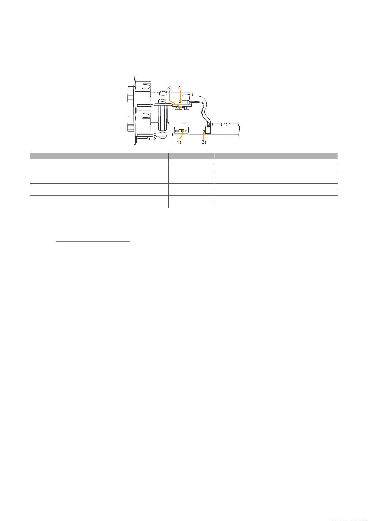
Technical data
4.2.4.14.3.5 Terminating resistor
A terminating resistor is already integrated on the IF option for each COM. This can be switched on or off
with a switch; it is necessary to open the system unit for this.
The terminating resistors are switched off on delivery. The state of the respective terminating resistor is
indicated by an LED (see "Reading LED status indicators" on page 193).
Assignment State Description
Color: Yellow
Color: Yellow
On Enabled1) COM A terminating resistor
Off Disabled
On COM A terminating resistor on2) LED status indicator for COM A terminating resistor
Off COM A terminating resistor off
On Enabled3) COM B terminating resistor
Off Disabled
On COM B terminating resistor on4) LED status indicator for COM B terminating resistor
Off COM B terminating resistor off
4.2.4.14.4 Driver support
Drivers for approved operating systems are available for download in the Downloads section of the B&R
website (www.br-automation.com) (if required and not already included in the operating system).
Approved operating systems:
•
Automation Runtime
•
Linux for B&R
•
Windows 10
Automation PC 3200 User's manual V1.00 87
Page 88
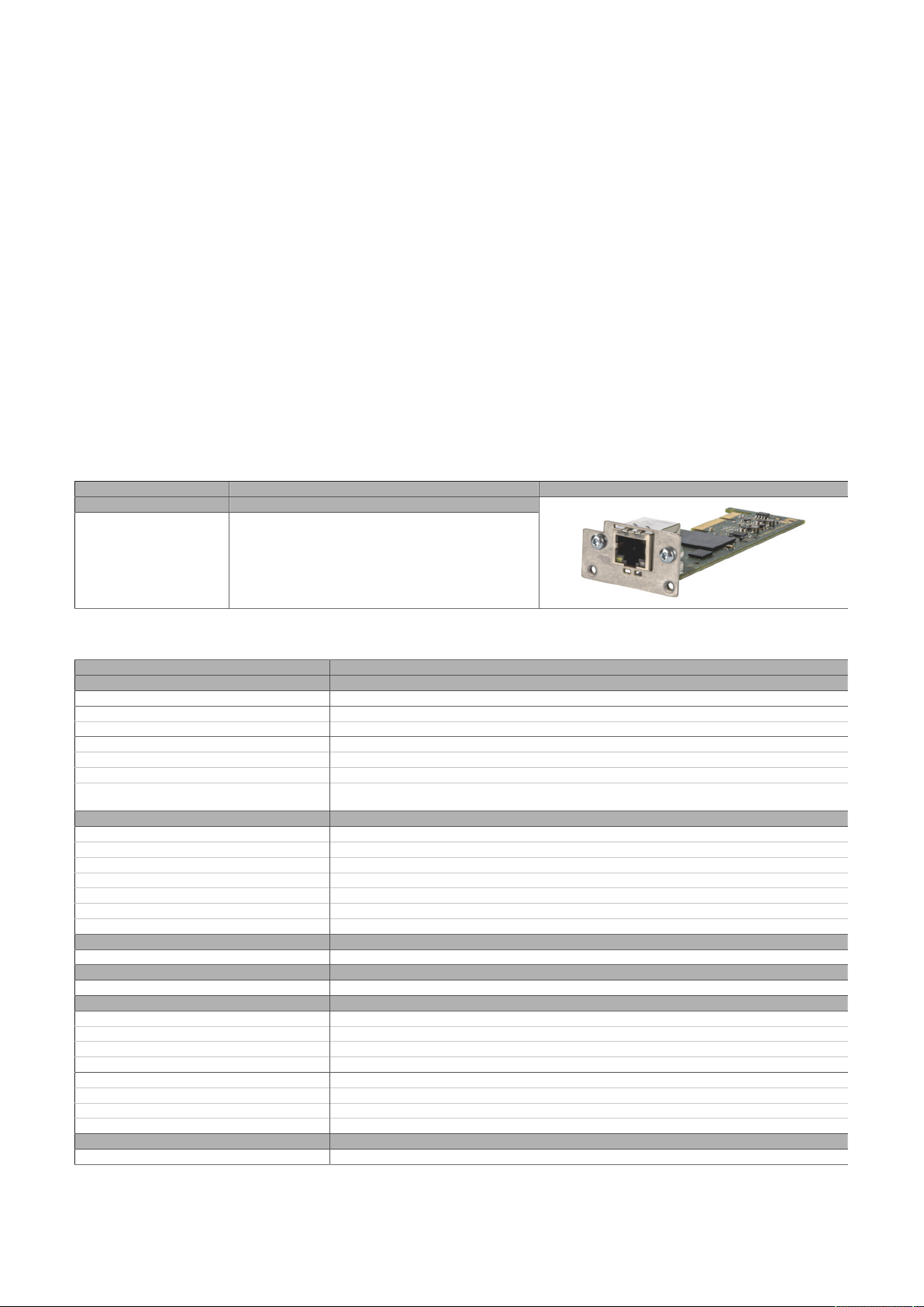
Technical data
4.2.4.15 5ACCIF04.FPLK-000
4.2.4.15.1 General information
Interface option 5ACCIF04.FPLK-000 is equipped with a POWERLINK interface.
•
1x POWERLINK interface (managing or controlled node) for real-time communication
•
Poll-response chaining
•
Compatible with APC3x00/PPC3x00 and APC4100
•
Easy installation in slot IF option 3.
•
Support in Automation Runtime and Automation Studio: Both starting with V4.9
Simultaneous operation with another POWERLINK interface card in slot IF option 2 with different addressing is possible. This allows parallel data acquisition from two separate networks.
With poll-response chaining (PRC), the IF option offers a solution for the highest demands on response time
and the shortest cycle times. When combined with the B&R control system, poll-response chaining provides
ideal performance, particularly for central control tasks.
This interface option can only be operated in the IF option 3 slot and is only supported by Automation
Runtime.
4.2.4.15.2 Order data
Order number Short description Figure
5ACCIF04.FPLK-000 Interface card - 1x POWERLINK interface - For APC3x00/
Interface options
PPC3x00 - For APC4100
4.2.4.15.3 Technical data
Order number 5ACCIF04.FPLK-000
General information
B&R ID code 0xFC5E
Diagnostics
Data transfer Yes, using LED status indicator
Certifications
CE Yes
UKCA Yes
UL cULus E115267
Interfaces
POWERLINK
Quantity 1
Type Type 4
Variant RJ45, shielded
Transfer rate 100 Mbit/s
Transfer 100BASE-TX
Line length Max. 100 m between two stations (segment length)
Electrical properties
Power consumption 1.5 W
Operating conditions
Pollution degree per EN 61131-2 Pollution degree 2
Ambient conditions
Temperature
Operation 0 to 55°C
Storage -20 to 60°C
Transport -20 to 60°C
Relative humidity
Operation 5 to 90%, non-condensing
Storage 5 to 95%, non-condensing
Transport 5 to 95%, non-condensing
Mechanical properties
Weight Approx. 25 g
1) For additional information, see Automation Help (Communication - POWERLINK - General information - Hardware - IF / LS).
Industrial control equipment
1)
88 Automation PC 3200 User's manual V1.00
Page 89
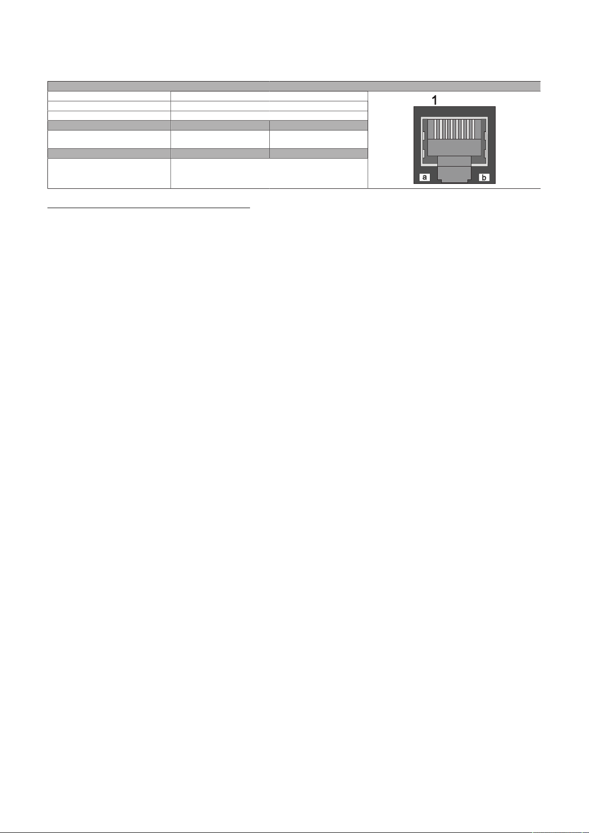
Technical data
4.2.4.15.3.1 Pinout
The POWERLINK interface is available in the IF option 3 slot.
Variant RJ45, female
Wiring S/STP (Cat 5e)
Cable length Max. 100 m (min. Cat 5e)
LED "Link" (a) On Active
Orange (light) Link (a connection to a POW-
ERLINK network exists)
LED "Status" (b) On Off
Green/Red POWERLINK status
see "LED "S/E" (status/error LED)" on page 190
POWERLINK interface
Blinking (data be-
ing transferred)
POWERLINK commissioning and operation
For a description of the operating modes, status and node numbers of the POWERLINK interface(s), see
"LED "S/E" (status/error LED)" on page 190.
4.2.4.15.3.2 Driver support and firmware update
The driver is part of the Automation Runtime and the firmware is part of Automation Studio. The module
is automatically brought up to this level.
To update the firmware contained in Automation Studio, a hardware upgrade must be performed (see
Project management / Workspace / Upgrades in Automation Help).
Automation PC 3200 User's manual V1.00 89
Page 90
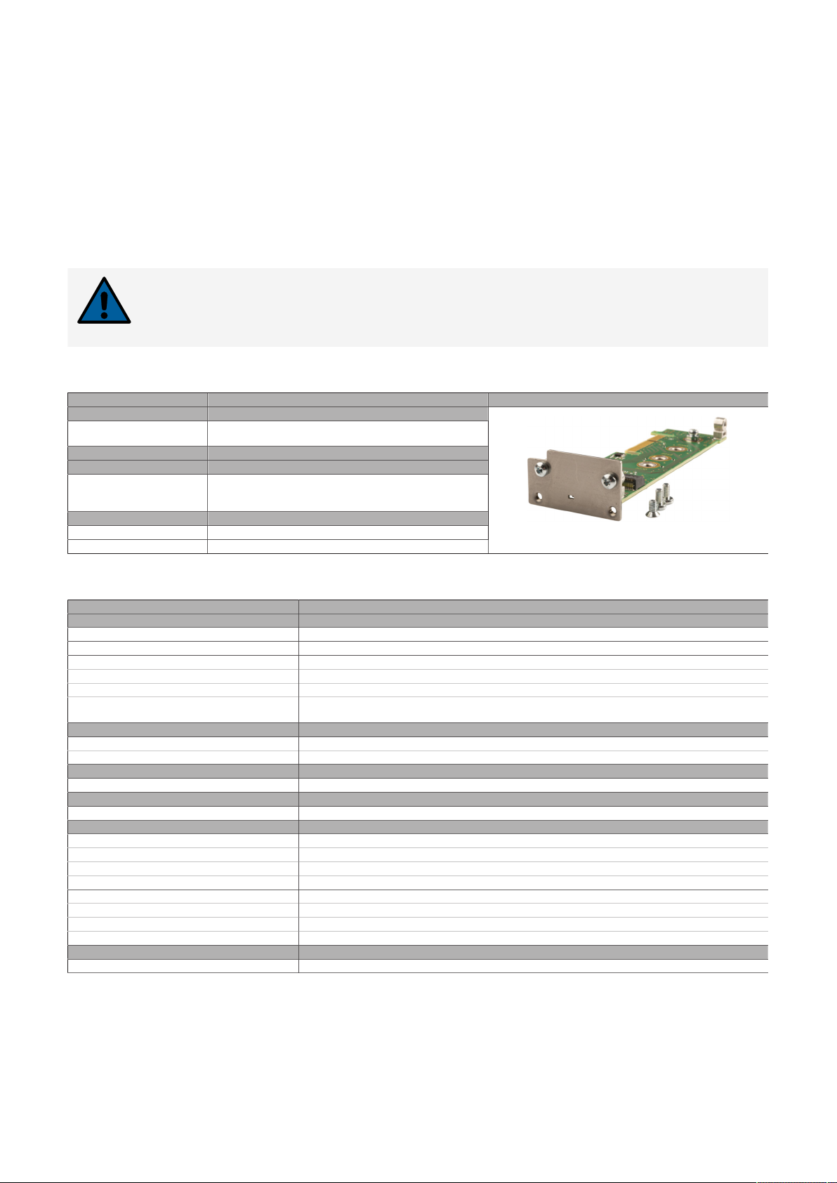
Technical data
4.2.5 Mass storage options
4.2.5.1 5ACCMS01.MDT2-000
4.2.5.1.1 General
5ACCMS01.MDT2-000 is an adapter card for M.2 mass storage devices. B&R offers two corresponding configurable M.2 solid-state drives (5ACCMSM2.xxxx-000).
•
Compatible in the APC3x00/PPC3x00 and APC4100 (only with 5ACCMBMS.0000-000)
•
Easy installation in slot IF option 3.
•
5ACCMSM2.xxxx-000 memory sizes: 512 GB or 1 TB
Notice!
B&R cannot guarantee the function of third-party M.2 mass storage devices. The functionality of mass storage devices available from B&R is ensured.
4.2.5.1.2 Order data
Order number Short description Figure
5ACCMS01.MDT2-000 Adapter card for M.2 mass storage - For APC3x00/PPC3x00
5ACCMBMS.0000-000 Mounting bracket for IF3 option - For APC4100 - Only for
5ACCMSM2.0512-000 512 GB M.2 SSD MLC - Innodisk - SATA
5ACCMSM2.1024-000 1 TB M.2 SSD MLC - Innodisk - SATA
Mass storage options
- For APC4100
Optional accessories
Accessories
1-/2-/3-slot - For IF options 5ACCLI05.SDL4-000 and 5ACCMS01.MDT2-000
Mass storage options
4.2.5.1.3 Technical data
Order number 5ACCMS01.MDT2-000
General information
LEDs Yes, 1x activity indicator
B&R ID code 0xFCCC
Certifications
CE Yes
UKCA Yes
UL cULus E115267
Interfaces
Add-on interface slot
Quantity 1x M.2 SSD; M-Key
Electrical properties
Power consumption Depends on the mass storage device used
Operating conditions
Pollution degree per EN 61131-2 Pollution degree 2
Ambient conditions
Temperature
Operation 0 to 55°C
Storage -20 to 60°C
Transport -20 to 60°C
Relative humidity
Operation 5 to 90%, non-condensing
Storage 5 to 95%, non-condensing
Transport 5 to 95%, non-condensing
Mechanical properties
Weight Approx. 35 g
1) These values can be limited by the mass storage device used.
2) Without mass storage device.
1)
Industrial control equipment
2)
90 Automation PC 3200 User's manual V1.00
Page 91

4.2.5.1.3.1 Status LED
Adapter card 5ACCMS01.MDT2-000 has a yellow LED status indicator
on the front panel that serves as an activity indicator.
•
On: Mass storage device being accessed (write or read procedure)
•
Off: Mass storage device not being accessed
Technical data
Automation PC 3200 User's manual V1.00 91
Page 92
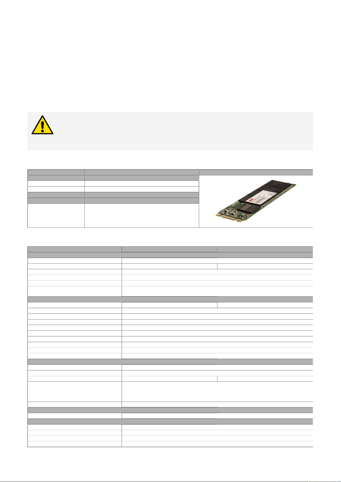
Technical data
4.2.5.2 5ACCMSM2.xxxx-000
4.2.5.2.1 General information
5ACCMSM2.xxxx-000 are M.2 mass storage devices (SSD) and can be used with adapter card
5ACCMS01.MDT2-000 as an interface option.
•
Compatible with APC3x00/PPC3x00 and APC4100 (using adapter card 5ACCMS01.MDT2-000)
•
Solid-state drives
•
MLC technology
•
SATA support
•
512 GB or 1 TB
Caution!
M.2 mass storage devices are not designed for hot-plugging or hot-swapping per the Next
Generation Form Factor (NGFF) specification. It is therefore not permitted to connect or
replace M.2 mass storage devices during operation.
4.2.5.2.2 Order data
Order number Short description Figure
5ACCMSM2.0512-000 512 GB M.2 SSD MLC - Innodisk - SATA
5ACCMSM2.1024-000 1 TB M.2 SSD MLC - Innodisk - SATA
5ACCMS01.MDT2-000 Adapter card for M.2 mass storage - For APC3x00/PPC3x00
Mass storage options
Optional accessories
Mass storage options
- For APC4100
4.2.5.2.3 Technical data
Order number 5ACCMSM2.0512-000 5ACCMSM2.1024-000
General information
Data retention
B&R ID code 0xFCCD 0xFCCE
Certifications
CE Yes
UKCA Yes
UL cULus E115267
Solid-state drive
Capacity 512 GB 1024 GB
Data reliability <1 unrecoverable error per 1015 bits read
MTBF 3,000,000 h
S.M.A.R.T. support Yes
Interface SATA
Continuous reading Max. 560 MB/s
Continuous writing Max. 450 MB/s
3)
IOPS
4k read Max. 76,000 (random)
4k write Max. 76,000 (random)
Endurance
MLC flash memory Yes
Guaranteed data volume
Client workload 600 TBW
Compatibility SATA 3.1 compliant
Storage health data support
Electrical properties
Power consumption Max. 3.5 W
Ambient conditions
Temperature
Operation -40 to 85°C
Storage -55 to 95°C
Transport -55 to 95°C
1)
Industrial control equipment
4)
SSD Enhanced SMART ATA feature set
5)
6)
Native Command Queuing (NCQ)
Yes, AR 4.90 and later
10 years
ACS-2
2)
1172 TBW
4)
92 Automation PC 3200 User's manual V1.00
Page 93

Technical data
Order number 5ACCMSM2.0512-000 5ACCMSM2.1024-000
Relative humidity
Operation 10 to 90%, non-condensing
Storage 10 to 95%, non-condensing
Transport 10 to 95%, non-condensing
Vibration
Operation 7 to 2000 Hz: 20 g
Storage 7 to 2000 Hz: 20 g
Transport 7 to 2000 Hz: 20 g
Shock
Operation 1500 g, 0.5 ms
Storage 1500 g, 0.5 ms
Transport 1500 g, 0.5 ms
Mechanical properties
Dimensions
Width 22 mm
Height 80 mm
Weight Approx. 15 g
Vendor information
Manufacturer Innodisk
Manufacturer's product ID M.2 (S80) 3MV2-P 512 GB M.2 (S80) 3MV2-P 1 TB
1) Per JEDEC (JESD47), EOL conditions are not permitted to be reached before 18 months. A higher average daily write workload reduces the expected
service life and data retention of the data storage medium.
2) At 25°C ambient temperature at the start of service life.
3) IOPS: Random read and write input/output operations per second
4) TBW: Terabytes written
Client workload per standard JEDEC JESD219
5) For details about storage health data, see Automation Help.
6) These values can be limited by the adapter card used.
4.2.5.2.4 Installing M.2 mass storage devices
The installation of M.2 mass storage devices in adapter card 5ACCMS01.MDT2-000 is described in section
"Installing M.2 mass storage devices" on page 176.
Automation PC 3200 User's manual V1.00 93
Page 94
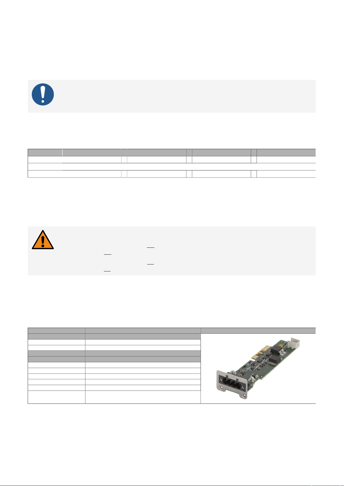
Technical data
4.2.6 Uninterruptible power supply
A B&R industrial PC equipped with a UPS can complete write operations even after a power failure. If the
UPS detects a power failure, it switches to battery operation immediately without interruption. All running
programs are safely terminated by the UPS software, and the system is shut down. Inconsistent data is
therefore ruled out.
The UPS must be configured, and the driver must be enabled.
Information:
External panels or monitors are not buffered by the UPS and will fail if the power supply
•
is lost.
Because the charging circuit is integrated in the housing of the B&R industrial PC, installation has been
reduced to simply attaching the connection cable to the battery unit installed next to the PC.
The batteries are accessible from the front and can be easily replaced for servicing.
The following combinations are permitted:
Capacity Battery unit Cables UPS IF option B&R industrial PC
4.5 Ah 5AC901.BUPS-00 + 5CAUPS.00xx-01 + 5AC901.IUPS-00 + 5xPCxxxx.xxxx-xxx
or
2.2 Ah 5AC901.BUPS-01 + 5CAUPS.00xx-01 + 5AC901.IUPS-01 + 5xPCxxxx.xxxx-xxx
4.2.6.1 5AC901.IUPS-0x
4.2.6.1.1 General information
UPS IF options 5AC901.IUPS-0x used together with the corresponding battery unit allows the B&R industrial
PC to be switched off properly without data loss during a power failure.
Warning!
UPS IF option 5AC901.IUPS-00 is only permitted to be operated with battery unit
5AC901.BUPS-00!
UPS IF option 5AC901.IUPS-01 is only permitted to be operated with battery unit
5AC901.BUPS-01!
This interface option can only be operated in slot IF option 1.
If the system is in power saving mode (S5: soft-off or S4: hibernate/suspend-to-disk), then the UPS IF option
charges the connected battery unit. The system's internal power supplies are active during this procedure.
This makes it possible to perform various actions (e.g. opening the built-in slide-in DVD drive).
4.2.6.1.2 Order data
Order number Short description Figure
5AC901.IUPS-00 UPS - For 4.5 Ah battery
5AC901.IUPS-01 UPS - For 2.2 Ah battery
5AC901.BUPS-00 Battery unit 4.5 Ah - For UPS 5AC901.IUPS-00
5AC901.BUPS-01 Battery unit 2.2 Ah - For UPS 5AC901.IUPS-01
5CAUPS.0005-01 UPS cable - 0.5 m - For 5AC901.IUPS-xx
5CAUPS.0010-01 UPS cable - 1 m - For 5AC901.IUPS-xx
5CAUPS.0013-01 UPS cable - 1.3 m - For 5AC901.IUPS-xx
5CAUPS.0030-01 UPS cable - 3 m - For 5AC901.IUPS-xx
Uninterruptible power supply
Required accessories
Uninterruptible power supply
94 Automation PC 3200 User's manual V1.00
Page 95
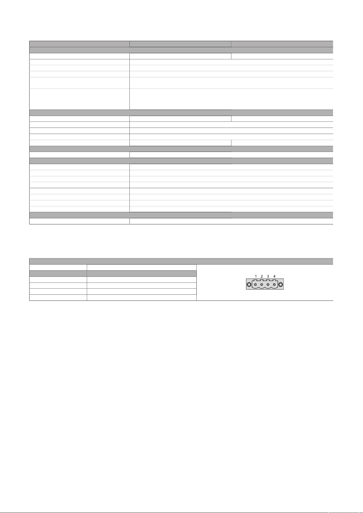
Technical data
4.2.6.1.3 Technical data
Order number 5AC901.IUPS-00 5AC901.IUPS-01
General information
B&R ID code 0xD851 0xDF84
Certifications
CE Yes
UKCA Yes
UL cULus E115267
HazLoc cULus HazLoc E180196
Electrical properties
Power consumption Max. 30 W at 1 A Max. 25 W at 0.9 A
Deep discharge protection Yes
Short-circuit proof Yes
Battery charging data
Charging current Typ. 1 A Typ. 0.88 A
Operating conditions
Pollution degree per EN 61131-2 Pollution degree 2
Ambient conditions
Temperature
Operation 0 to 55°C
Storage -20 to 60°C
Transport -20 to 60°C
Relative humidity
Operation 5 to 90%, non-condensing
Storage 5 to 95%, non-condensing
Transport 5 to 95%, non-condensing
Mechanical properties
Weight Approx. 28 g
1) The interface option is short-circuit proof. This value does not apply to the connected battery unit.
2) For detailed information, see the temperature tables in the user's manual.
Industrial control equipment
Industrial control equipment
for hazardous locations
Class I, Division 2, Groups ABCD, T4
1)
2)
4.2.6.1.4 Pinout
Variant 4-pin, male
Pin Pinout
1 Temperature sensor
2 Temperature sensor
3 4 +
UPS interface
4.2.6.1.5 Installation
This module is installed using the materials included in delivery. For additional information about installation, see section "Installing the interface option and DDR4 SDRAM" on page 173.
Automation PC 3200 User's manual V1.00 95
Page 96
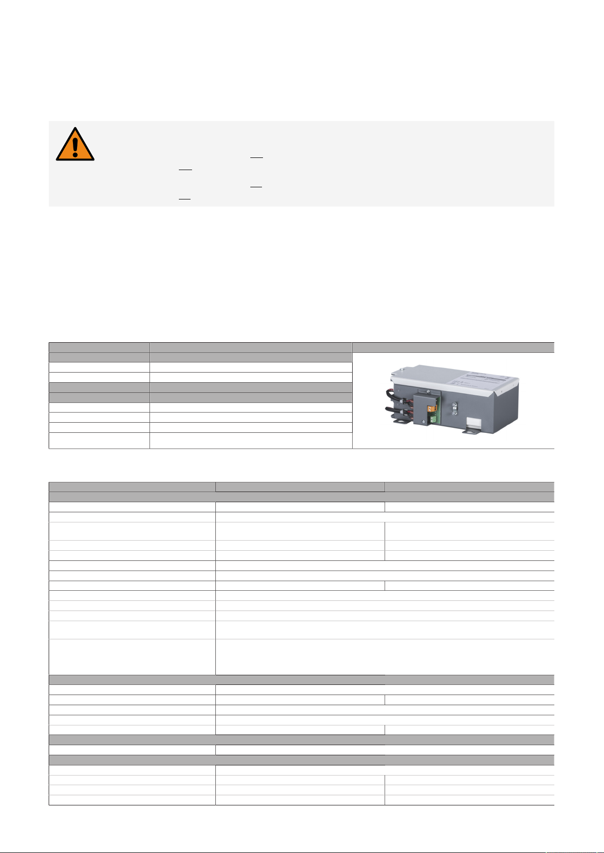
Technical data
4.2.6.2 5AC901.BUPS-0x
4.2.6.2.1 General information
The battery unit is subject to wear and should be replaced regularly (after the specified service life at the
latest).
Warning!
Battery unit 5AC901.BUPS-00 is only permitted to be operated with UPS IF option
5AC901.IUPS-00!
Battery unit 5AC901.BUPS-01 is only permitted to be operated with UPS IF option
5AC901.IUPS-01!
If the max. specified temperature limits of the battery unit are overshot or undershot, the temperature
alarm of the battery unit is set. Battery backing is no longer provided if the temperature alarm for the
battery unit is active. The battery is also no longer charged since this can result in damage to the battery.
This temperature alarm is defined with a hysteresis of 5°C. The temperature alarm is therefore only deleted
again when the minimum temperature limit is overshot again by this hysteresis or the maximum temperature limit is undershot again by this hysteresis. The temperature or temperature alarm of the battery unit
is not only monitored and checked at runtime, but also when the system is powered on; it can be evaluated
using the B&R ADI library.
4.2.6.2.2 Order data
Order number Short description Figure
5AC901.BUPS-00 Battery unit 4.5 Ah - For UPS 5AC901.IUPS-00
5AC901.BUPS-01 Battery unit 2.2 Ah - For UPS 5AC901.IUPS-01
5CAUPS.0005-01 UPS cable - 0.5 m - For 5AC901.IUPS-xx
5CAUPS.0010-01 UPS cable - 1 m - For 5AC901.IUPS-xx
5CAUPS.0013-01 UPS cable - 1.3 m - For 5AC901.IUPS-xx
5CAUPS.0030-01 UPS cable - 3 m - For 5AC901.IUPS-xx
Uninterruptible power supply
Required accessories
Uninterruptible power supply
4.2.6.2.3 Technical data
Order number 5AC901.BUPS-00 5AC901.BUPS-01
General information
B&R ID code 0xD82E 0xDF83
Battery
Type Hawker Cyclon 12 V, 4.5 Ah, two recharge-
Service life Up to 15 years at 20°C / 10 years at 25°C
Variant Single cell (VRLA) Maintenance-free lead acid battery (VRLA)
Temperature sensor NTC resistance
Service interval during storage Charge 1 time every 6 months
Charge duration when battery low Typ. 7 hours Typ. 5 hours
Certifications
CE Yes
UKCA Yes
UL cULus E115267
HazLoc cULus HazLoc E180196
Electrical properties
Nominal voltage 24 V
Capacity 4.5 Ah 2.2 Ah
Fuse Yes
Battery charging data
Charging current
Operating conditions
Pollution degree per EN 61131-2 Pollution degree 2
Ambient conditions
Temperature
Operation -30 to 60°C
5)
Storage
Transport
3)
5)
able batteries connected in series
Industrial control equipment
Industrial control equipment
for hazardous locations
Class I, Division 2, Groups ABCD, T4
Typ. 1 A Typ. 0.88 A
4)
-65 to 65°C -15 to 40°C
-65 to 65°C -15 to 40°C
1)
96 Automation PC 3200 User's manual V1.00
12 V, 2.2 Ah, two rechargeable
batteries connected in series
Up to 5 years at 20°C
0 to 40°C
2)
4)
Page 97
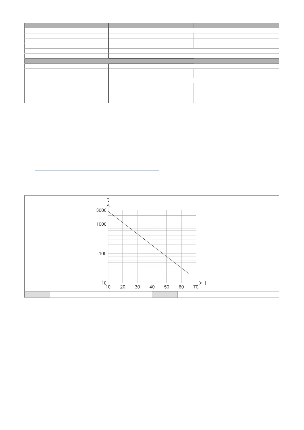
Technical data
Order number 5AC901.BUPS-00 5AC901.BUPS-01
Relative humidity
Operation 5 to 95%, non-condensing 25 to 85%, non-condensing
Storage 5 to 95%, non-condensing 25 to 85%, non-condensing
Transport 5 to 95%, non-condensing 25 to 85%, non-condensing
Elevation
Operation Max. 3000 m
Mechanical properties
Housing
Material Rev. D0 and later: Steel, galvanized and coated
Up to Rev. C0: Steel, galvanized
Dimensions
Width 223.2 mm 188 mm
Height 78.2 mm 78 mm
Depth 145 mm 115 mm
Weight Approx. 4600 g Approx. 2550 g
1) Depends on the charging and discharging cycles (up to 80% battery capacity).
2) Depends on the charging and discharging cycles.
3) Maximum charging current.
4) Battery backing is no longer provided if the temperature undershoots the minimum temperature or overshoots the maximum temperature.
The battery is also no longer charged since this can result in damage to the battery.
5) See also "Discharge time and ambient temperature diagram" in the user documentation.
Rev. E0 and later: Steel, galvanized and coated
Up to Rev. D0: Steel, galvanized
Note about the safe handling of lead-acid batteries
For additional information, see the following documents:
•
5AC901.BUPS-00 - Material safety data sheet (VRLA)
•
5AC901.BUPS-01 - Material safety data sheet (VRLA)
Discharge time / Ambient temperature diagram
Only valid for 5AC901.BUPS-00.
t Time in days (storage/transport) T Temperature in °C
Automation PC 3200 User's manual V1.00 97
Page 98
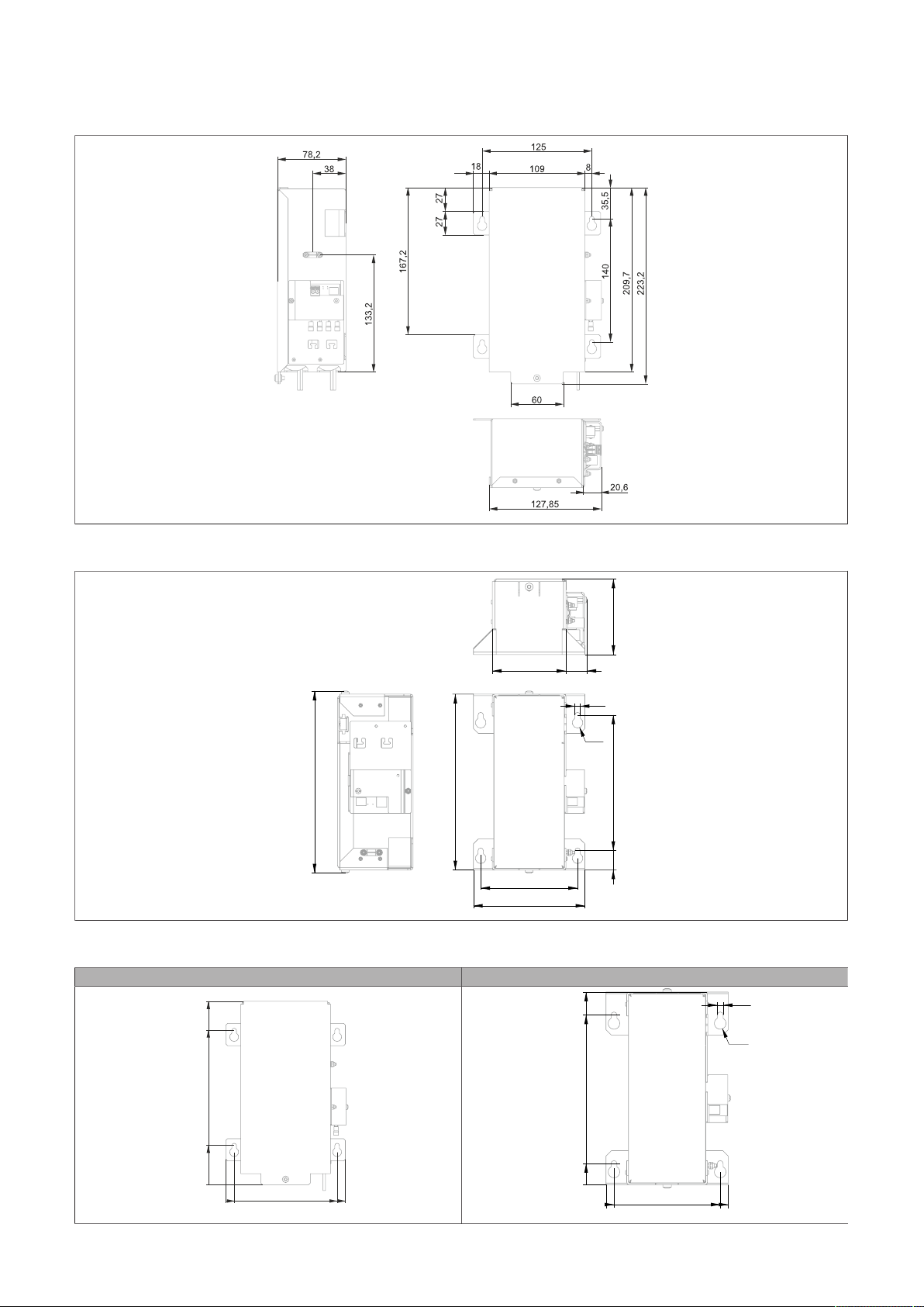
Technical data
181.5
115
78
14020
100
188
76
21.6
5.5
ø 11
47.7
0010 135 145
187.7
223.2
181.5
115
140
20
107.5
5.5
ø 11
7.5
0
0
4.2.6.2.3.1 Dimensions
5AC901.BUPS-00
5AC901.BUPS-01
4.2.6.2.3.2 Drilling template
5AC901.BUPS-00 5AC901.BUPS-01
98 Automation PC 3200 User's manual V1.00
Page 99

Technical data
4.2.6.2.4 Installation
For information about installation and connecting to the UPS IF option, see section "Installing and connect-
ing the UPS battery unit" on page 177.
4.2.6.2.5 Precautions for handling and use
Spills and leaks:
Further leakage must be prevented. Smaller spills must be bonded with dry sand, dirt and vermiculite. The
use of flammable materials is not permitted. If possible, neutralize acids with sodium bicarbonate, chalk,
etc. Acid-resistant clothing, shoes, gloves as well as acid-resistant face protection must be worn. The disposal of unneutralized acid in the sewage system is prohibited!
Waste disposal:
Used batteries and rechargeable batteries must be disposed of in an environmentally friendly recycling
process.
Neutralized mud must be stored in closed containers and stored / disposed of in accordance with applicable regulations. After neutralization and inspection, larger spills diluted with water must be disposed of
in accordance with applicable regulations.
Handling and storage:
•
Store in cool, dry and well-ventilated rooms with impermeable surfaces and appropriate containment
conditions in case of leakage.
•
Protect from adverse weather conditions and separate from incompatible materials during storage
and transport.
•
A sufficient supply of water must be located nearby.
•
Prevent damage to containers in which batteries and rechargeable batteries are stored and transported.
•
Keep away from fire, sparks and heat.
Automation PC 3200 User's manual V1.00 99
Page 100
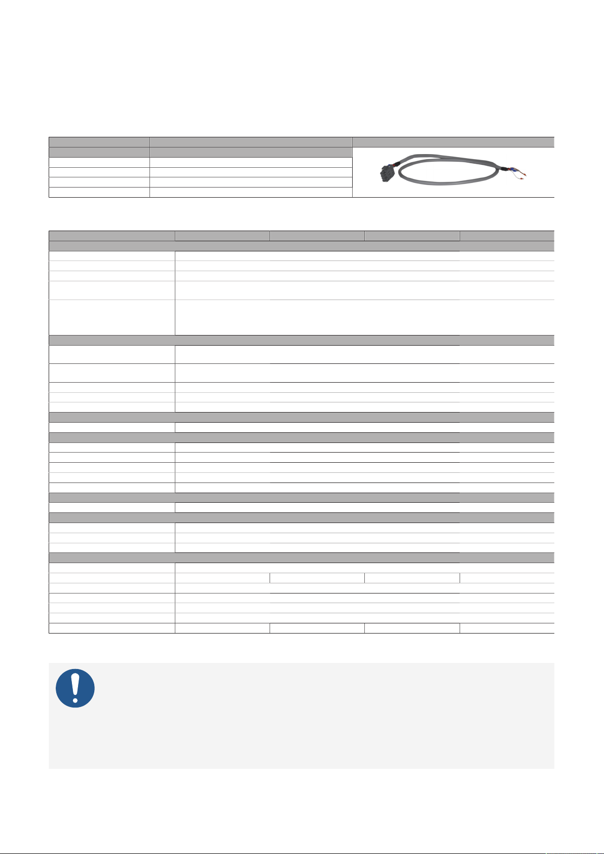
Technical data
4.2.6.3 5CAUPS.xxxx-01
4.2.6.3.1 General information
The UPS connection cable establishes the connection between the UPS interface option and battery unit.
4.2.6.3.2 Order data
Order number Short description Figure
5CAUPS.0005-01 UPS cable - 0.5 m - For 5AC901.IUPS-xx
5CAUPS.0010-01 UPS cable - 1 m - For 5AC901.IUPS-xx
5CAUPS.0013-01 UPS cable - 1.3 m - For 5AC901.IUPS-xx
5CAUPS.0030-01 UPS cable - 3 m - For 5AC901.IUPS-xx
Uninterruptible power supply
4.2.6.3.3 Technical data
Order number 5CAUPS.0005-01 5CAUPS.0010-01 5CAUPS.0013-01 5CAUPS.0030-01
General information
Certifications
CE Yes
UKCA Yes
UL cULus E115267
HazLoc cULus HazLoc E180196
Cable construction
Wire cross section 2x 0.5 mm2 (20 AWG)
Conductor resistance At 0.5 mm2 max. 39 Ω/km
Outer jacket
Material Thermoplastic PVC-based material
Color Window gray (similar to RAL 7040)
Connector
Type 4-pin screw clamp terminal block
Electrical properties
Operating voltage Max. 30 VDC
Peak operating voltage Typ. 30 VDC
Test voltage
Wire - Wire 1500 V
Current-carrying capacity 10 A at 20°C
Operating conditions
Pollution degree per EN 61131-2 Pollution degree 2
Ambient conditions
Temperature
Moving -5 to 70°C
Static -30 to 70°C
Mechanical properties
Dimensions
Length 0.5 m 1 m 1.3 m 3 m
Diameter 7 mm
Bend radius
Moving 10x line diameter
Fixed installation 5x line diameter
Weight Approx. 55 g Approx. 100 g Approx. 130 g Approx. 250 g
1) At an ambient temperature of 20°C.
2) Tightening torque: Min. 0.4 Nm, max. 0.5 Nm
Industrial control equipment
Industrial control equipment
for hazardous locations
Class I, Division 2, Groups ABCD, T4
2x 2.5 mm2 (13 AWG)
At 2.5 mm2 max. 7.98 Ω/km
1)
2)
Information:
The maximum length of the UPS connection cable depends on the following:
Power output
•
Voltage drop
•
Wire cross section
•
Sensor line
•
100 Automation PC 3200 User's manual V1.00
 Loading...