

Page 1
USERS GUIDE
BOXLIGHT 6000
Revolution III
19332 Powder Hill Place
Poulsbo, WA 98370-7407 USA
www.boxlight.com
Direct Phone:
USA: (360) 779-7901
Europe: +44 (0) 1732-840-404
Free phone within these areas:
United Kingdom: 0800-762-575
Germany: 0800-180-8381
France: 0800-9132-88
USA and Canada: 800-762-5757
Page 2
\ 2 \
CAUTION: TO REDUCE THE RISK OF ELECTRIC SHOCK, DO NOT REMOVE COVER (OR
BACK). NO USER-SERVICEABLE PARTS INSIDE. REFER SERVICING TO QUALIFIED
SERVICE PERSONNEL.
THIS SYMBOL INDI CA TES THAT DA NGEROUS VOLTAGE CONSTITUTING A RISK O F
ELECTRIC SHOCK IS PRESENT WITHIN
THIS UNIT.
THIS SYMBOL INDICATES THAT THERE ARE
IMPORTANT OPERATING AND
MAINTENANCE INSTRUCTIONS IN THE
USER'S GUIDE WITH THIS UNIT.
RISK OF ELECTRIC SHOCK
DO NOT OPEN
CAUTION
TO THE OWNER
SAFETY PRECAUTIONS
INFORMATION TO THE USER
NOTE: This equipment has been tested and found to comply with the limits for a Class A digital device, pursuant to
Part 15 of the FCC Rules. These limits are designed to provide reasonable protection against harmful
interference when the equipment is operated in a commercial environment. This equipment generates,
uses, and can radiate radio frequency energy and, if not installed and used in accordance with the user's
guide, may cause harmful interference to radio communications. Operation of this equipment in a residential
area is likely to cause harmful interference in which case the user will be required to correct the interference
at his own expense.
As the owner of the Revolution , you are probably eager to try out your new projector. Before you do, we suggest
that you spend a little time reading this guide to familiarize yourself with the operating procedures, so that you will
receive maximum satisfaction from the many features included in your new projector.
This user's guide will acquaint you with your projector's features. Reading it will help us too. Through the years, we
have found that many service requests were not caused by problems with our projectors. They were caused by
problems that could have been prevented, if the owner had followed the instructions in the guide.
You can often correct operating problems yourself. If your projector fails to work properly, see
"TROUBLESHOOTING" section on pages 49 - 50 and try the solutions marked for each problem.
WARNING:
TO REDUCE THE RISK OF FIRE O R ELECTRIC SHOCK, DO NOT EXPO SE THIS APPLIANCE TO RAIN OR
MOISTURE.
The
Revolution
has a grounding-type AC lin e pl ug. Th is i s a safety feature to be sure that th e pl ug wil l fi t
into the power outlet. Do not try to defeat this safety feature.
Intense light source. Do no t stare directly i nto the p rojection lens as possible eye damage could result. Be
especially careful that children do not stare directly into the beam.
If the Revolution will not be used for an extended time, unplug the Revolution
from the power outlet.
READ AND KEEP THIS USER'S GUIDE FOR LATER USE.
Page 3
\ 3 \
IMPORTANT SAFETY INSTRUCTIONS
All the safety and ope rating instruct ions should be read
before the product is operated.
Read all of the ins tru ct ions given her e and ret ain them f or
later use. Unplug this project or from AC power supply
before cleaning. Do not use liquid or aerosol cleaner s.
Use a damp clot h for cleaning.
Do not use attachments not recommended by the
manufacturer as they may cause hazards.
Do not pla ce this projec tor on an u nstable car t, sta nd, or
table. The pro jector may fall, causin g serious injur y to a
child or adult, and serio us damage to the pr ojector. Use
only with a cart or stand recommended by the
manufactur er, or sold with the pr ojector. Wall or shelf
mounting should follo w t he manufacturer's inst ructions,
and should use a mounting kit approved by the
manufacturer.
Do not expose this unit to rain or use near wat er for
example, in a we t basement, near a swimming pool, etc.
Slots and open ings in the back and bot tom of the cabinet
are pr ovided fo r vent ilatio n, to ins ure re liable oper ation o f
the equipment and to protect it from overheating .
The openings sho uld n ever be co ver ed with clot h or oth er
material, and the bott om opening sho uld not be bloc ked
by placing the projecto r on a bed, sofa, rug, or other
similar surf ace. This project or should never be placed
near or over a radiator or heat register.
This project or s hould no t be pla ced in a built- in in st alla tion
such as a bookcase unless proper ventilation is provided .
This projector should be operat ed only from the type of
power source ind icated on the mar king label. If y ou are
not sure of the type of power supplied, consult your
authorized de aler or local power company.
Do not ov erload wall outlets and extens ion cords as this
can result in fire or electric shock. Do n ot allow anything to
rest o n the power c ord. Do not locate this p r ojector where
the cord m ay be damaged by p ersons walking on i t.
Never push o bjects of an y kind into th is project or thr ough
cabinet s lots as t hey m ay tou ch dange rou s volt age poin ts
or short out parts that could result in a fire or electric
shock. Never s pill liquid of any kind on the project o r .
Do not attempt to service this projector yourself as
opening or removing covers may expose you to
dangerous voltage or other hazards. Refer all servicing to
qualified serv ic e personnel.
Unplug this pro jec tor from wall outlet and r efer servicing to
qualified service personne l under the following conditions:
a. When the po wer cord or plug is damaged or fr ayed.
b. If liquid has been spilled into t he projector.
c. If the projector has been exposed to rain or water.
d. If the pr ojector do es not opera te normally b y following
the operating ins tructions. Adjust only those controls
that are covered by the operating instructions as
improper adjust ment of other controls may r esult in
damage and will oft en require extensive wor k by a
qualified technician to rest ore the projector to norm al
operation.
e. If the projector h as been dropped or the ca bin et has
been damaged.
f. When the projector exhibits a distinct change in
performa nc e - this indicates a need for ser v ic e.
When replace m ent parts ar e re quir ed, be sure the serv ice
technician has us ed replacement part s specified by the
manufacturer that have the same characteristics as the
original par t. Unauthor ized su bstit ut ions m ay re sult in fir e,
electric shoc k , or injury to persons.
Upon completion of any service or repairs to this
projector, a sk the service tec hnician to perfor m routine
safety checks to determine that the projector is in safe
operating con dition.
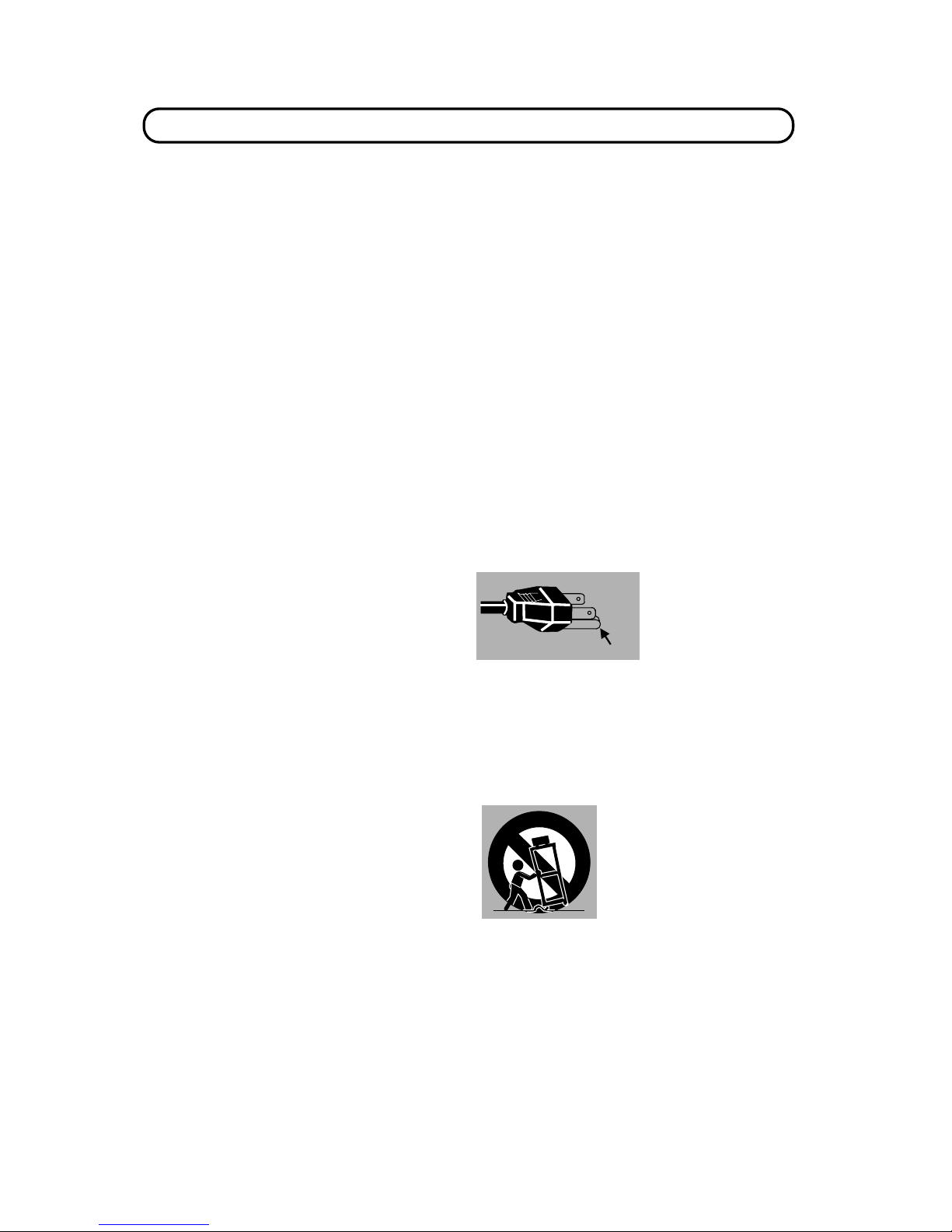
This projector is e quipped
with a grounding ty pe AC
line plug. Should you be
unable to insert the plug
into the out let, c ontac t your
electrician. Do not defeat
the safety purpose of this
grounding type plug.
Follow all warnings and instructions marked on the
projectors.
For added prot ection to the proje ctor during a lightn ing
storm, or when it is lef t unattende d and unused for long
periods of tim e, unplug it from the wall ou tlet. This will
prevent dam a ge due to lightning and powerline sur g es .
An applian ce an d car t combinat ion
should be moved with car e. Quick
stops, excessive force, and uneven
surf aces may caus e the appliance
and cart combination to overturn.
GROUND
Page 4

TABLE OF CONTENTS
\ 4 \
PAGE
INTRODUCTION 5
COMPATIBILITY 5
IMAGE RESOLUTION 5
PORTABILITY 5
UNPACKING THE PROJECTOR 5
TRADEMARKS 5
POWER REQUIREMENT 6
DESCRIPTION 7
SETTING-UP THE PROJECTOR 8-9
POSITIONING 8
ROOM LIGHT 8
VENTILATION 8
LEVELING AND ELEVATING ADJUSTMENTS 9
MOVING THE PROJECTOR 9
CONNECTING THE PROJ ECTOR 10-17
CONNECTING THE COM P UTER 10-14
Connecting an IBM-compat ib le desktop comp uter 11
Connecting a M ac intosh desktop computer 12
Connecting an IBM-compat ib le laptop comput e r 13
Connecting a Macintosh PowerBook computer 14
CONNECTING THE VIDEO EQUIPMENT 15-16
CONNECTING AN EXTERNAL S PEAK ER 17
OPERATION OF CONTRO LS 18-20
TOP OF THE PROJECTOR 18-19
REAR OF THE PROJECTOR 20
OPERATION OF REMOTE CONTROL 21-23
REMOTE CONTROL BA TTERY INSTALLATION 23
USING THE REMO TE CONTROL UNIT 23
CONTROL THE PROJECTOR 24-26
DIRECT OPERATION 24
MENU OPERATION 25-26
USING THE PROJECTOR 27-46
TO TURN ON THE PROJECTOR 27
TO TURN OFF THE PROJECTO R 27
DIRECT OPERATION 28
MODE SELECT 28
SOUND VOLUME ADJ USTMENT 28
PAGE
SOUND MUTE FUNCTION 28
ZOOM ADJUSTMENT 28
FOCUS ADJUSTMENT 28
NORMAL PICTURE FUNCTIO N 28
FREEZE PICTURE FUNCTION 28
FINE SYNC ADJUSTMENT 28
MENU OPERATION 29-46
MODE SELECT 29
SOUND ADJUSTMENT 30
LANGUAGE ADJUSTMENT 30
MENU EXIT 30
COLOR SYSTEM SELECT 31
PICTURE IMAGE ADJUSTMENT 32
PICTURE SCREEN ADJUSTMENT 33
COMPUTER SYSTEM SELECT 34
COMPATIBLE COMPUTER SPECIFICATION
35
PICTURE IMAGE ADJUSTMENT 36
PICTURE POSITION ADJUSTMENT 37
PC ADJUSTMENT 38-41
AUTO IMAGE FUNCTI ON 42
PICTURE SCREEN ADJUSTMENT 43
OTHER FUNCTION SETTI NG 44-46
AUTO RETRACT 44-45
BLUE BACK 44-45
DISPLAY 44-45
CEILING 44-45
REAR 44-45
LAMP AGE 46
AIR FILTER CARE AND CLEANING 47
TEMPERATURE WARNING I NDICATOR 47
LAMP REPLACEMENT 48
CLEANING THE LENS 49
TROUBLESHOOTING 49-50
TECHNICAL SPECIFICATIONS 51
Page 5

INTRODUCTION
The Revolu tion¡is a mult imedia pro jector de signed fo r porta bility, du rability, and ease of u se. The Revolu tion utilizes
built-in multimedia featur e s , a palette of 16.77 million color s , and active ma trix liquid crys tal display (LCD) technology.
COMPATIBILITY
The projector is c o m patible with many d ifferent ty p es of personal computers and vid eo devices, inclu din g;
IBM-compatible computers, including lapt ops, up to 1280 x 10 2 4 resolution.
Apple Macinto s h a nd PowerBook computers up to 1280 x 1024 r e s olution.
Various VCRs, vid eo dis c p lay e r s , video cameras, satellite TV tuners or ot her AV equipmen t us ing any of the wo r ld wide
video stand ards NTSC, NTSC4.43, P AL an d S ECAM .
IMAGE RESOLUTION
The reso lution of the pr ojector 's pr ojected im age is 1024 x 768. The p rojecto r display s comput er imag es just as they
appear on your computer's monitor. Screen resolutions between 1024 x 768 and 1280 x 1024 are compressed to 1024
x 768. The projector cannot display screen resolutions above 1280 x 1024. If your computer's screen r esolution is
higher than 128 0 x 1 024, reset it to a lower resolu t ion before you co nn ec t the project o r.
PORTABILITY
The projector is extre mely compact in size and we ight. Having a sophistica ted shape like an attac hÈ case with a
retractab le c ar r ying han dle , th e pr oje ct o r will help yo u ma ke powe rf u l pr es ent at ions whe re ver you go. To st r eng t hen t he
portability, t he LENS RETRACT f unc t ion is des igned t o pr ot e ct t he len s f r om be ing da ma ged du rin g tr an spo rt a t ion. Wit h
this function, the lens is pu lled in when not in use.
UNPACKING THE PROJECTOR
The projec tor com es wit h the par ts sho wn listed below. Check t o ma ke sure a ll are includ ed. I f any par ts ar e miss ing,
contact Boxlight.
User's Guide.
AC Power Cord.
Remote Contro l Tr ansmitter Unit and batter ies.
Lens Cover.
Protectiv e Du s t Cover.
VGA Cable.
VGA/MAC Adapter.
Mouse Cable for P S/2 port.
Mouse Cable for s erial port.
Mouse Cable fo r A DB p ort.
TRADEMARKS
Apple, Macintosh, and PowerBook ar e tr ademarks or registered trademarks of Apple Computer, Inc.
IBM and PS/2 are trademarks or registered trademarks of International Business Machines, Inc.
\
5
\
Page 6
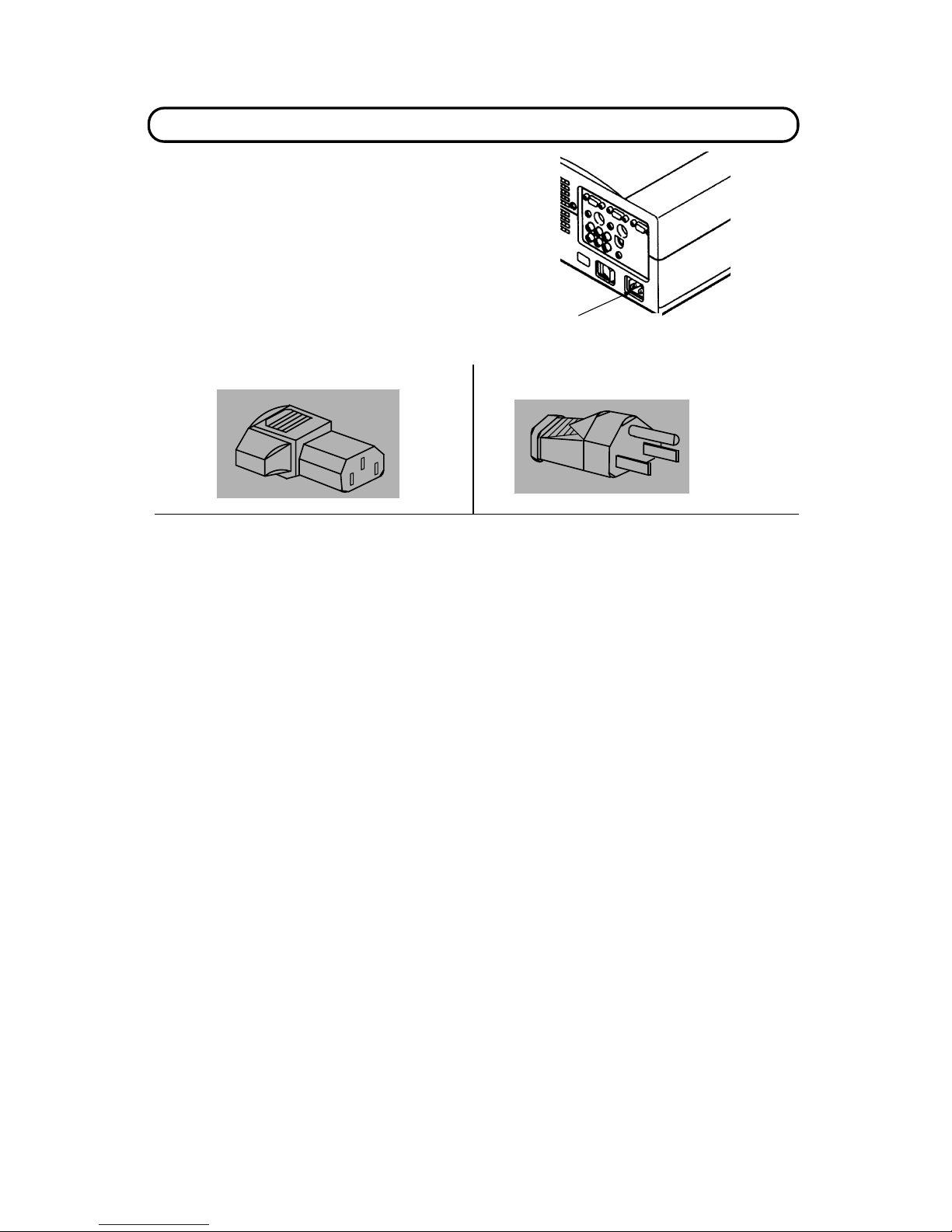
Projector side (Female) AC outlet side (Male)
POWER REQUIREMENTS
Y
our projector uses nominal input voltages of 100-120
VAC
or
200-240 VAC. The pr ojector automatic ally selects the corr ect
input voltage. The projector is designed to work with
single-phase power systems having a grounded neutral
conductor. To reduce the risk of electrical shock, do not plug into
any other type of power system. Consult your authorized dealer
or service stat ion if y ou are not sure what type of power is
supplied to your building.
\ 6 \
Connect the AC power
supply cord (s upplied) to
the projector.
Page 7
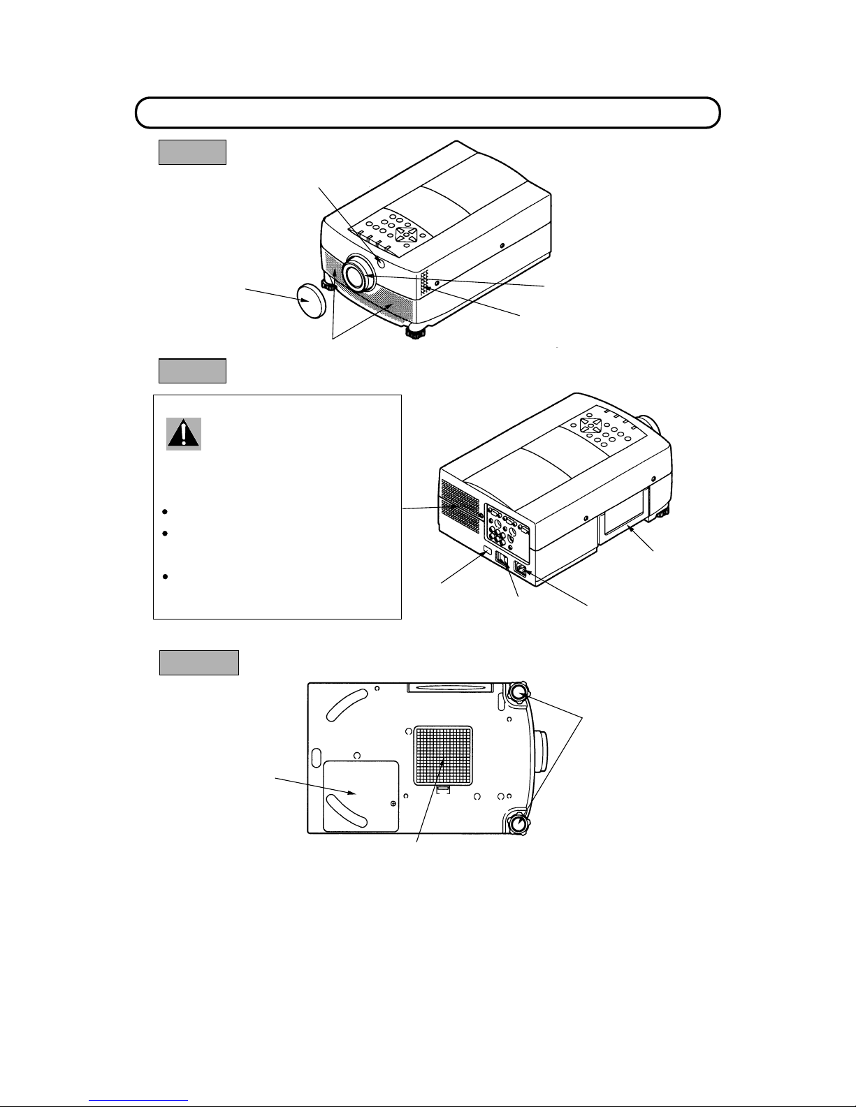
DESCRIPTION
\ 7 \
REMOVABLE
LENS COVER
FRONT
PROJECTION LENS
SPEAKER
INFRARED
REMOTE
RECEIVER
AIR INTAKE
VENT
REAR
MAIN ON/OFF
SWITCH
EXHAUST VENT
CARRY HANDLE
INFRARED
REMOTE
RECEIVER
POWER CORD
CONNECTOR
CAUTION HOT AIR !
Air blown from the exhaust vent is hot.
Observe the following when handling your
projector or choosing a location to instal l it.
Keep heat-sensitive objects away from the
exhaust port.
If you set the proje ctor on top of a metallic
surface, the sur face will become hot becaus e
of the hot air exhaust. Be careful when
handling.
Do not touch t he cabinet near the exha ust
vent ar ea, and espe cially screws and me tallic
parts. Thes e parts will become h ot while the
projector is us ed.
BOTTOM
AIR INTAKE
VENT
LAMP COVER
LEVELING/ELEVATING
FEET
Page 8
ROOM LIGHT
Ideally the projec tor should be placed in a
room with limited light. Pict ure quality will be
directly affected by light ing c onditions.
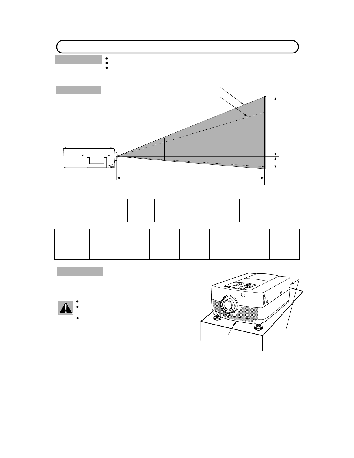
SETTING-UP THE PROJECTOR
This projector is basically designed to project on a flat project io n s urface.
This projector c an be focused from 3.6' ( 1.1m) - 47' (14.3m).
Use the illustra tion below as an example when positioning the projector to the sc reen.
POSITIONING :
100"
200"
300"
188"
125"
62"
Minimum Zoom
Maximum Zoom
DISTANCE
400"
250"
H1
H2
This projector is equipped wit h a cooling fan t o pr otect it from
overheating. Pay at tent ion to t he f ollowing t o en sure t he v entilat ion
and avoid a possible risk of fire and malfunctio n.
VENTILATION
Do not cover t he vents with pa pe r s or other ma terials.
Keep the rear grill at least 3.3 ' (1m) away from any
object.
Make sure that there are no objects under the
projector. An object under t he projector may pr event
the projector from t aking the cooling air through the
bottom vent.
20"
Screen Size
(W ~H) inch
Height (H1)
Height (H2)
16 x 12
60"
100"
150"
200"
300"
400"
49 x 36
80 x 60 120 x 90
160 x 120 240 x 180
320 x 240
32 inch
4 inch
53 inch
7 inch
80 inch
10 inch
106 inch
14 inch
160 inch
20 inch
212 inch
28 inch
10.7 inch
1.3 inch
Min. Zoom
Max. Zoom
20"
32"
Distance
100"
150"
200"
300"
Screen
Size
62" 94"
125"
188"
60"
37"
400"
250"
3.6'(1.1 m)
6.9'(2.1 m) 11.8'(3.6 m)
17.8'(5.4 m)
23.7'(7.2 m)
35.2'(10.7 m) 47'(14.3 m)
\
8
\
EXHAUST VENT
(REAR SIDE)
AIR INTAKE VENT
(BOTTOM SIDE)
Page 9
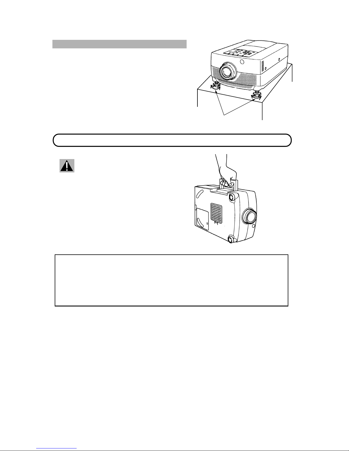
LEVELING AND ELEVA TING ADJUSTMENTS
Use the carry ha nd le when moving the p r ojector.
MOVING THE PROJECTOR
Two feet adjust the projection a ngle.
The projection angle can be adjusted up to 6 ° degrees by
rotating the two (left and right) feet located on the bottom of the
projector.
Retract th e lens, replac e the lens cove r and r ota te
the leveling/elevation feet fully clockwise when
moving the projector to prevent damage to the
projector.
CAUTION IN CARRYING OR TRANSPORTING THE PROJECTOR
Do not drop or b u m p the projector , otherwise damage or mulfun c tion may result .
When carrying the projector, use a Boxlight recommended Carrying Case.
Do not t ransp ort the project or by using a courie r or tran spor t ser vice in an unsuit able t rans port case. This ma y
cause dam age to th e projec tor. To t ran sport t he proje ctor throu gh a courie r or tr anspo rt ser vice, u se a Boxligh t
recommended Case.
For a carrying o r t ransportation cases, con t ac t a Boxlight aut horized dealer.
\
9
\
DOWN
UP
UP
DOWN
LEVELING/ELEVATION
FEET
Page 10
CONNECTING THE PROJECTOR
12345
7
10
11121314
HDB15-PIN
TERMINAL
6
8
9
15
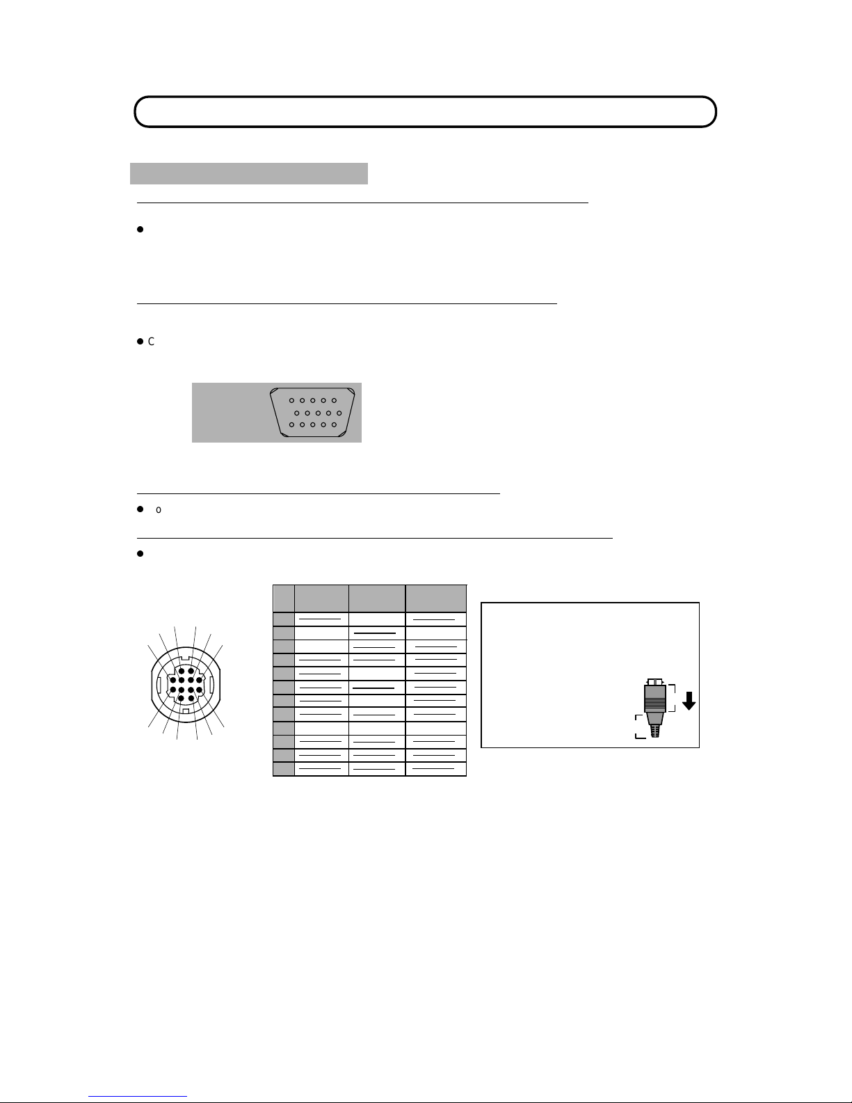
Your project o r is eq uip ped wit h v ar ious a udio/ v ideo in pu ts an d ou t put s in clud ing Com put e r HDB1 5- pin (V G A) t e rm ina ls,
Monitor HDB15-pin (VGA) terminals and S-VHS video .
CONNECTING THE COMPUTER
CONNECTING TO THE COMPUTER INPUT HDB15-PIN (VGA) TERMINALS (1 and 2)
Personal comp uters can be co nn ec ted to the HDB15-pin (VGA) t e r minal on the pr oje c tor.
z
Connect the c omputer to these terminals using th e VGA cable and VGA /MAC adapter (provided).
WARNING: For projectors, the VGA cable provided is designed to reduce RFI (Rad io Fr equency Inter ference)
emissions. Fo r reg ulator y com pliance r eason s, t his cab le mus t be used and must not b e rep laced by any
other cable.
CONNECTING TO THE MONITOR OUTPUT HDB15-PIN (VGA) TERMINAL
This terminal contains the information that is viewed on the screen.
Monitor can b e c onnected to the HDB15-pin (VGA) terminal on the projecto r .
z
Connect the monitor to this terminal us ing the monitor c ab le (not provided).
CONNECTING TO THE COMPUTER AUDIO INPUT JACKS (1 and 2)
z
Connect audio outputs from your computer to these jacks using t he audio cable (not provided).
CONNECTING TO THE MULTI-POLE 12-PIN (CONTROL PORT) CONNECTORS (1 and 2)
z
If you wish to control the computer with projector's remote control unit, you must connect control port (PS/2, Serial or
ADB port) on your computer to projecto r 's control p ort with cable. ( three type ca bles provided)
\
10
\
Pin No./Si
gna
l
Pin No./Si
gna
l
1 Red input 9 Non Connect
2 Green input 10 Ground (Vert. sync.)
3 Blue input 11 Sense 0
4 Sense 2 12 Sense 1
5 Ground (Horiz. sync.) 13 Horiz. sync.
6 Ground (Red) 14 Vert. sync.
7 Ground (Green) 15 Reserved
8 Ground (Blue)
ADB
READ
Y
Serial
Port
12
11
10
9
8
7
6
5
4
3
2
1
CLK
PS/2
Port
DATA
GND
TxD
GND
GND
2
¡ CONTROL PORT
1
6
5
4
3
7
8
9
10
1112
ADB
Port
A
B
CONTROL PORT CABLE
REMOVAL HINT
Disconnect control port cable
with following ste ps .
1. Hold the portion (A) of the
connecto r with one hand.
2. Pull the portion (B) a r row
direction and remove
connector.
ƒRxD
ƒ
NOTE: The RxD port (5 p in on t he Serial Port) is pr ovided on control port 2 c onnector only. If you control t he
projector by computer, you must connect control port 2 connector.
Page 11
COMPUTER
INPUT 1 or 2
COMPUTER
AUDIO INPUT
1 or 2
AUDIO
OUTPUT
SERIAL PORT
INPUT
CONTROL PORT
OUTPUT 1 or 2
MONITOR
OUTPUT
COMPUTER
OUTPUT
PS/2
PORT INPUT
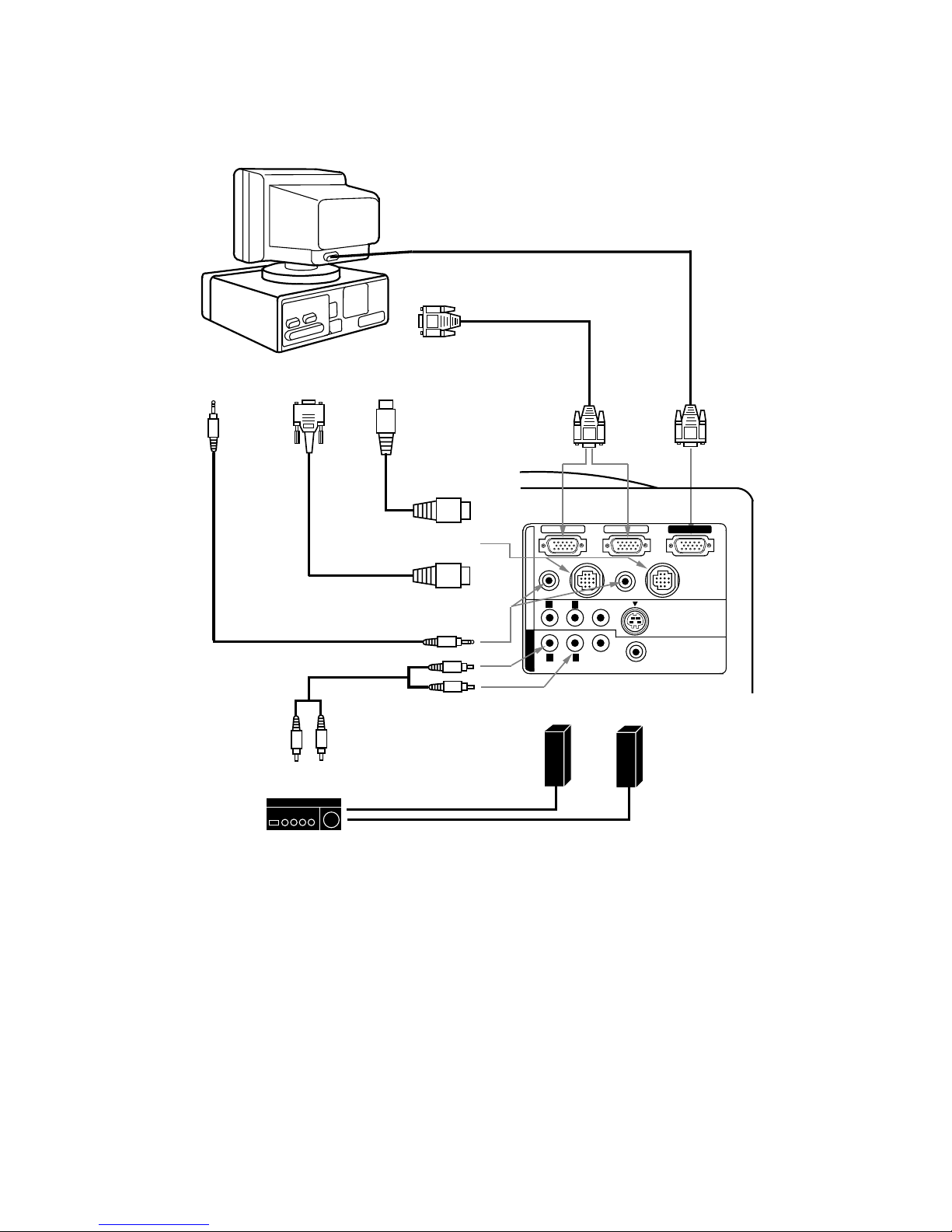
Connecting an IBM-compatible desktop computer
COMPUTER
MONITOR CABLE
(NOT PROVIDED)
VGA CABLE
(PROVIDED)
MOUSE CABLE
FOR PS/2 PORT
(PROVIDED)
MOUSE CABLE
FOR SERIAL PORT
(PROVIDED)
AUDIO CABLE
(NOT PROVIDED)
COMPUTER IN 1
MONITOR OUT
CONTROL PORT 1
AUDIO
(MONO)
VIDEO
AUDIO
VIDEO
EXT. SP
(8 ¶)
S-VIDEO
AV IN
COMPUTER
MONITOR OUT
COMPUTER IN 2
AUDIO 1
(STEREO)
(STEREO)
CONTROL PORT 2
AUDIO 2
(STEREO)
L
L
R
R
NOTE: The hook up s h ould be done as per the above illustration. After hook up, t urn on the projector, monitor,
computer, in that order.
R
L
AUDIO MONITO R
OUTPUT
AUDIO
INPUT
Amp.
SPEAKER
OUT
Speaker (L)
Speaker (R)
L
R
\
11
\
Page 12
COMPUTER
INPUT 1 or 2
COMPUTER
AUDIO INPUT
1 or 2
AUDIO
OUTPUT
CONTROL PORT
OUTPUT 1 or 2
MONITOR
OUTPUT
COMPUTER
OUTPUT
ADB
PORT INPUT
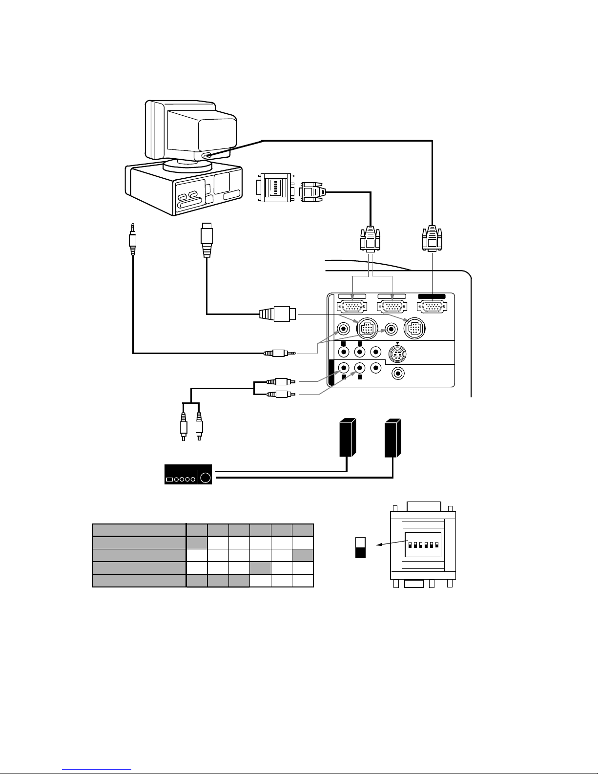
Connecting a Macintosh desktop computer
ON
1
2
3 4 5
6
VGA/MAC ADAPTER
(PROVIDED)
COMPUTER
VGA CABLE
(PROVIDED)
MONITOR CABLE
(NOT PROVIDED)
MOUSE CABLE
FOR ADB PORT
(PROVIDED)
AUDIO CABLE
(NOT PROVIDED)
ON
1
2
3 4 5
6
13" MODE (640 ~480)
RESOLUTION MODE
SW1
16" MODE (832 ~624)
ON
OFF
SW2
SW3
SW4 SW5 SW6
OFF
ON
OFF
OFF
OFF
OFF OFF OFF
OFF OFF
VGA/MAC ADAPTER
Set the s lide switches a s shown in the t able below depe nding on
the RESOLUTION MODE that you want to use before you turn on
the projector and computer.
ON
OFF
SW1 ‘ SW6
19" MODE (1024 ~768)
21" MODE (1152 ~870)
ON
ON
ON
ON
OFF
OFF
OFF
OFF
OFF
OFF
OFF OFF
COMPUTER IN 1
MONITOR OUT
CONTROL PORT 1
AUDIO
(MONO)
VIDEO
AUDIO
VIDEO
EXT. SP
(8 ¶)
S-VIDEO
AV IN COMPUTER
MONITOR OUT
COMPUTER IN 2
AUDIO 1
(STEREO)
(STERE O)
CONTROL PORT 2
AUDIO 2
(STERE O)
L
L
R
R
NOTE: The hook up s h ould be done as per the above illustration. After hook up, t urn on the projector, monitor,
computer, in that order.
R
L
AUDIO MONITOR
OUTPUT
AUDIO
INPUT
Amp.
SPEAKER
OUT
Speaker (L)
Speaker (R)
L
R
\
12
\
Page 13
COMPUTER
INPUT 1 or 2
COMPUTER
AUDIO INPUT
1 or 2
AUDIO
OUTPUT
SERIAL PORT
INPUT
CONTROL PORT
OUTPUT 1 or 2
COMPUTER
OUTPUT
PS/2
PORT INPUT
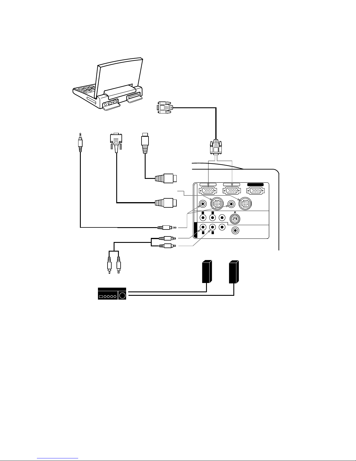
Connecting an IBM-compatible laptop computer
COMPUTER
VGA CABLE
(PROVIDED)
MOUSE CABLE
FOR PS/2 PORT
(PROVIDED)
MOUSE CABLE
FOR SERIAL PORT
(PROVIDED)
AUDIO CABLE
(NOT PROVIDED)
COMPUTER IN 1
MONITOR OUT
CONTROL PORT 1
AUDIO
(MONO)
VIDEO
AUDIO
VIDEO
EXT. SP
(8 ¶)
S-VIDEO
AV IN
COMPUTER
MONITOR OUT
COMPUTER IN 2
AUDIO 1
(STERE O)
(STEREO)
CONTROL PORT 2
AUDIO 2
(STEREO)
L
L
R
R
NOTE: The hook up s hould be done as per the above illust r a tion. After h ook up, turn o n the project or, computer,
in that orde r .
R
L
AUDIO MONITO R
OUTPUT
AUDIO
INPUT
Amp.
SPEAKER
OUT
Speaker (L)
Speaker (R)
L
R
\
13
\
Page 14
COMPUTER
INPUT 1 or 2
COMPUTER
AUDIO INPUT 1 or 2
AUDIO
OUTPUT
CONTROL PORT
OUTPUT 1 or 2
ADB
PORT INPUT
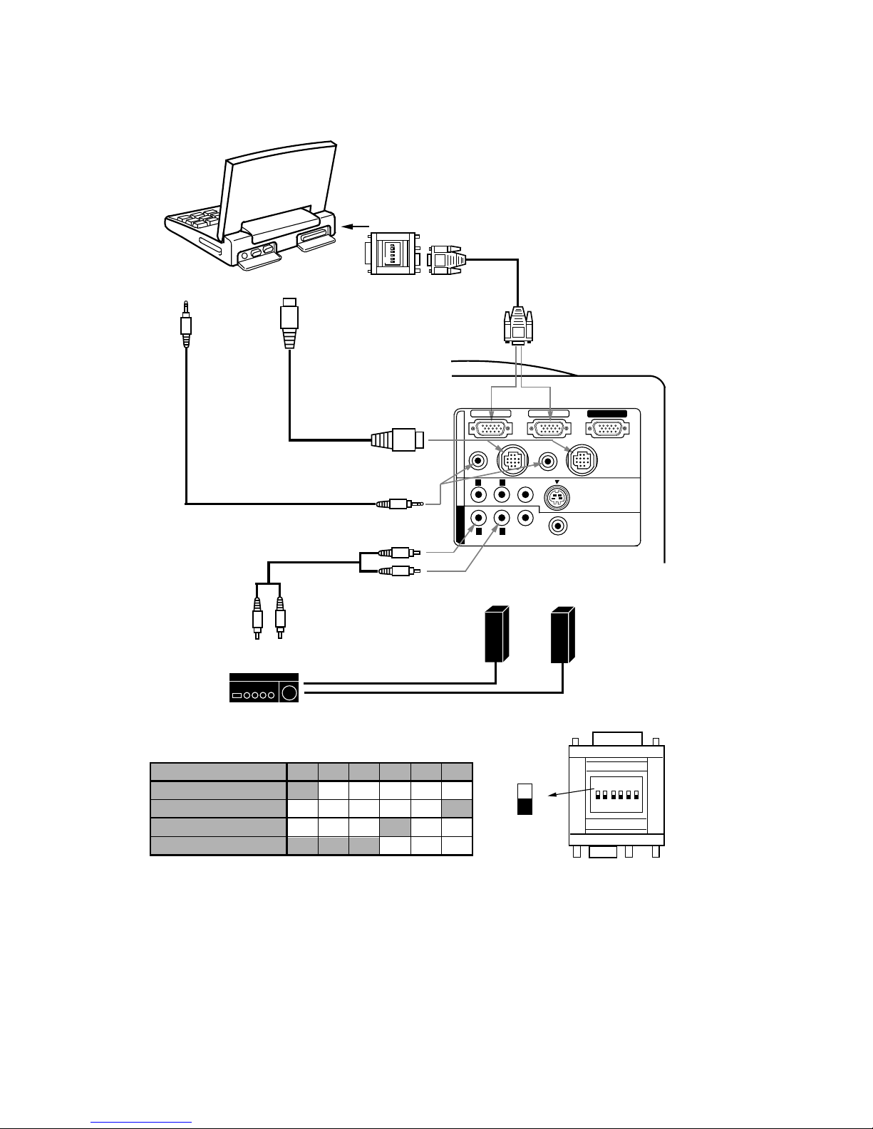
Connecting a Macintosh PowerBook computer
ON
1
2
3
4 5
6
VGA/MAC ADAPTER
(PROVIDED)
VGA CABLE
(PROVIDED)
COMPUTER
AUDIO CABLE
(NOT PROVIDED)
MOUSE CABLE
FOR ADB PORT
(PROVIDED)
ON
1
2
3 4 5
6
VGA/MAC ADAPTER
ON
OFF
SW1 ‘ SW6
Set the slid e s witches a s s hown in the t able below depen ding on
the RESOLUTION MODE that you want to use before you turn on
the projector and computer.
The Macintosh PowerBook requires the use of the
PowerBook Video Adapter shipped with the
PowerBook.
TO POWERBOOK
VIDEO ADAPTER
COMPUTER IN 1
MONITOR OUT
CONTROL PORT 1
AUDIO
(MONO)
VIDEO
AUDIO
VIDEO
EXT. SP
(8 ¶)
S-VIDEO
AV IN COMPUTER
MONITOR OUT
COMPUTER IN 2
AUDIO 1
(STEREO)
(STERE O)
CONTROL PORT 2
AUDIO 2
(STERE O)
L
L
R
R
NOTE: The hook up s ho uld be done as per the above illustr ation. Aft er hook up, tu r n on the project or, compute r ,
in that orde r .
13" MODE (640 ~480)
RESOLUTION MO DE
SW1
16" MODE (832 ~624)
ON
OFF
SW2
SW3
SW4 SW5 SW6
OFF
ON
OFF
OFF
OFF
OFF OFF OFF
OFF OFF
19" MODE (1024 ~768)
21" MODE (1152 ~870)
ON
ON
ON
ON
OFF
OFF
OFF
OFF
OFF
OFF
OFF OFF
R
L
AUDIO MONITO R
OUTPUT
AUDIO
INPUT
Amp.
SPEAKER
OUT
Speaker (L)
Speaker (R)
L
R
\
14
\
Page 15

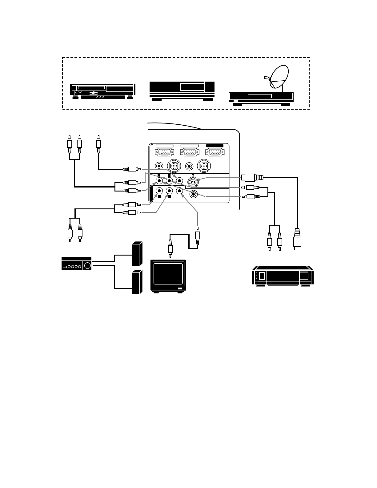
CONNECTING THE VIDEO EQUIPMENT
CONNECTING TO THE AV INPUT JACKS
Connect to the v ideo and audio output s of a VCR, video disc player, video ca mera, sat ellite TV tuner or ot her AV
equipment.
z
Connect audio/video outputs from external sour ces to these input jacks using the audio/video cable.
z
If the audio signa l f rom t he AV equipme nt is ster eo, be s ure to c onnect the right and le ft c hannels to t he resp ective
right and left audio input jacks.
z
If the external audio signal is monaural, connect it to the left jack.
S-VHS FORMAT VCR CONNECTION
The AV input inc ludes a n ex t r a v ideo inpu t jac k m ar k ed S- VIDE O to allow connectio n to a n S- VHS fo rm at VCR that ha s
separate Y/ C video signals. The S-VIDEO jack h a s priority over the VIDEO jac k .
CONNECTING TO THE VIDEO MONI TOR OUTPUT JACK
This ja ck will conta in the v ideo inform ation of t he select ed progr am sourc e video only. If you selec t prog ram sou rce
Computer 1 or Computer 2, there is no signa l.
Connect video inp ut from AV equipment to this jack by RCA cable.
Whenever the S-VIDEO s ignal sou rce is viewed on the sc reen, t he video s ignal availab le at the MONI TOR OUTPUT
jack will be in black and white (monochr o m e).
CONNECTING TO THE AUDIO MONITOR OUTPUT JACKS
These jacks will contain the au dio infor m at ion of t he select ed pr ogra m source be ing viewed on the scr een ( Compu t er 1,
Computer 2 or Vid eo 1). I f you hav e select ed pr ogra m sourc e Compu ter 1 th e audio sign al co nnec ted to t he Compu ter
1 audio input jack will be availab le a t the audio monitor output jacks.
z
If the audio input of the au dio equipment is ster eo, be su re to conne ct the righ t and left ch annels to the resp ective
right and left jacks.
z
If the audio input of the a ud io equipment is mo naural, connec t it to the left jack.
\
15
\
Page 16
S-VHS VCR
AUDIO
OUTPUT
S-VIDEO
OUTPUT
AUDIO INPUT
R
L
AUDIO MONITO R
OUTPUT
AUDIO
INPUT
Amp.
SPEAKER
OUT
Speaker (L)
Speaker (R)
VIDEO
INPUT
MONITOR
VIDEO INPUT
AUDIO
INPUT
Video Cassette Recorder
L R
AUDIO
OUTPUT
VIDEO
OUTPUT
Video Disc Player
Satellite
TV Tuner
VIDEO EQUIPMENT
S-VIDEO
INPUT
L
R
VIDEO
MONITOR
OUTPUT
Connecting the Video Equipment
NOTE
: The hook up should be done as per the above illust ration. Aft er hook up, t urn on the projec tor, video eq uip m ent,
in that o r der.
COMPUTER IN 1
MONITOR OUT
CONTROL PORT 1
AUDIO
(MONO)
VIDEO
AUDIO
VIDEO
EXT. SP
(8 ¶)
S-VIDEO
AV IN
COMPUTER
MONITOR OUT
COMPUTER IN 2
AUDIO 1
(STERE O)
(STEREO)
CONTROL PORT 2
AUDIO 2
(STEREO)
L
L
R
R
\
16
\
Page 17

EXTERNAL
SPEAKERS SYSTEM
COMPUTER IN 1
MONITOR OUT
CONTROL PORT 1
AUDIO
(MONO)
VIDEO
AUDIO
VIDEO
EXT. SP
(8 ¶)
S-VIDEO
AV IN
COMPUTER
MONITOR OUT
COMPUTER IN 2
AUDIO 1
(STERE O)
(STEREO)
CONTROL PORT 2
AUDIO 2
(STEREO)
L
L
R
R
CONNECTING AN EXTERNAL SPEAKER
CONNECTING TO THE EXT. SP. JACK (3.5mm mini stereo type)
This jack outp uts ste reo speaker sound which viewing on screen. If yo u use exte rnal speaker system, co nnect st ereo
type extern al speaker jack. Internal sp ea k er sound is discon nected when spea k er jack is connected.
\
17
\
Page 18

OPERATION OF CONTROLS
1
10
11
12
13
14
15
2
3
4
5
6
7
8
9
TOP CONTROL
LAMP
REPLACE
WARNING
TEMP.
READY
LAMP
MENU
SYSTEM
NORMAL
MODE
ON-OFF
ZOOM
FOCUS
FINE SYNC
VOLUME
\ 18 \
TOP
CONTROL
TOP OF THE PROJECTOR
Page 19

LAMP POWER ON/OFF BUTTON
Used to turn projection lamp on or off.
LAMP POWER INDICATO R
Light is dim when the projector is on.
Light is brightened when the pr o jec tor is in stand-by mode.
READY INDICATOR
Light is green whe n projector lamp is ready to be turned on.
TEMPERATURE WARNING INDICATOR
Flashes red when internal projec tor temperature is too hig h.
LAMP REPLACEMENT INDICATOR
Light is orange when projection lamp is nearing end of service life.
MODE BUTTON
Used to select v ideo source.
(Computer 1, Computer 2 or Video 1 Input )
VOLUME BUTTONS
Used to adjust v olume.
SYSTEM BUTTON
Computer Mode
Use this button, the POINT UP/DOWN/LEFT/RIGHT buttons and the SELECT button to select computer
system.
VIDEO Mode
Use this button, the POINT UP/DOWN/LEFT/RIGHT buttons and the SELECT button to select color system .
SELECT BUTTON
This butt on has diff ere nt f unct ions depending on when us ed. This butt on is us ed t o exe cute the ite m sele cted , t o
increase or de c r ease the values in c ertain items s uch as CONTRAST or BRIGHTNESS.
MENU BUTTON
This button will activate the M ENU o peration.
Use this button, the POINT UP/DOWN/LEFT/RIGHT buttons and the SELECT button to make adjustments to the
projector's s etting in MENU op eration.
POINT UP/DOWN/LEFT/RIG HT BUTTONS
To select an item on the MENU that you want to ad just. To select a n item, move the ar row by p ressing these
buttons (UP, DOWN, LEFT or RIGHT).
Used to operate power zoom lens or power focus system. (Pressing these button either UP or DOWN)
NORMAL BUTTON
Used to reset to normal picture adjustment preset by factory.
FINE SYNC BUTTONS
Used to adjust fine sync.
4
3
2
1
5
8
6
10
9
11
14
7
9
15
ZOOM BUTTON
Used to select power zoom lens adjust.
12
FOCUS BUTTON
Used to select focus adjust.
13
\
19
\
Page 20

REAR OF THE PROJECTOR
COMPUTER INPUT-2 TERMINAL
Used to connec t a computer to the projec tor.
MONITOR OUTPUT TERM INAL
Used to connect a monitor to the projector.
COMPUTER AUDIO I NPUT-1 JACK
mini stereo type
Used to connect a computer a udio input to th e
projector.
CONTROL PORT-1 CONNECTOR
Used to connec t a mouse cable t o the project or.
AUDIO INPUT JACKS
Used to connec t an audio input to the projector.
VIDEO INPUT JACK
Used to connec t a video source to the projec tor.
S-VIDEO IN PUT JACK
Used to connect a S-VHS video source to the projector .
AUDIO MONITOR OUTPUT JACKS
Permits audio connection to a monitor .
VIDEO MONITOR OUTPUT JACK
Permits video connection to a monitor.
EXT. SP. JACK (3.5 m m mini stereo t ype)
Used to connect an external speaker system.
16
20
17
18
19
20
23
24
25
26
27
28
17
18
19
21
22
23
24
25
26
27
28
COMPUTER INPUT-1 TERMINAL
Used to connect a computer to the projector.
16
COMPUTER AUDIO I NPUT JACK 2
mini stereo type
Used to connect a computer a udio input to th e
projector.
CONTROL PORT-2 CONNE CTOR (SERIAL PORT)
Used to connec t a mouse cable t o the project or.
21
22
COMPUTER IN 1
MONITOR OUT
CONTROL PORT 1
AUDIO
(MONO)
VIDEO
AUDIO
VIDEO
EXT. SP
(8 ¶)
S-VIDEO
AV IN
COMPUTER
MONITOR OUT
COMPUTER IN 2
AUDIO 1
(STEREO)
(STERE O)
CONTROL PORT 2
AUDIO 2
(STERE O)
L
L
R
R
NOTE: Control port- 2 c onnec tor c an be al so used
as serial port .
\
20
\
Page 21

OPERATION OF REMOTE CONTROL
FRONT
SIDE
This r emote cont rol unit is not o nly able to opera te the pr ojector
but also u sable as a wirele ss mouse for a P C. One point ing pad
and two click but tons are used f o r wireless mouse op eration.
Wireless mous e is usa ble wh en PC m ou se po int er is d ispla yed on
the screen. When the menu or indicator of the projector is
displayed on the screen inste ad of t he PC mou se pointer, the
wireless mouse ca nnot be used.
NOTE
: To use the unit as a PC wireless mouse , connect the
projector to the PC with the attached cable. Signals from
the projector are transmitted to the PC, enabling the
remote contr ol unit of the projector to be used as a PC
wireless mouse. (Refer to "CONNECTING THE
PROJECTOR" in pages 10 to 14 for the connection.)
14
M
E
N
U
O
N
O
F
F
F
R
E
E
Z
E
1
2
3
5
6
7
9
4
E
C
M
O
D
E
VO
L
U
M
E
8
Z
M
F
O
C
U
S
O
O
M
L
S
Y
S
T
E
M
10
11
12
13
\
21
\
Page 22

NORMAL BUTTON
Use to reset to normal picture adjustment preset by factory.
LAMP POWER ON/OFF BUTTON
Used to turn the projectio n la m p on or off.
MENU BUTTON
This butt on will act ivate the M ENU operat ion. Us e this b utto n, t he POI NT UP/DO WN/LE FT/RIG HT butt on and
the SELECT (REAR CLI CK) button to make adjustm e nts to the pr ojector's setting in MENU operation.
SOUND MUTE BUTTON
Used to mute sound.
VOLUME BUTTONS
Used to adjust v olume.
MODE BUTTON
Used to select video source. (Computer 1, Computer 2 or Video 1 Input)
2
4
10
6
3
1
8
7
POINTING PAD
(POINT UP/DOWN/LEFT/RIGHT BUTTON)
When in use as a remote for the projector.
To select an item on the MENU that you want to adjust. To select an item, move the arr ow by pressing the pad
upward, downward, leftwar d or rightward.
Used to operate p owe r zo om lens or power focus syst e m b y pressing the pad either up wa rd or downward.
When in use as a wireless mouse
Used to move the pointer. Th e pointer is mov ed according to the direction you are pressing.
FRONT CLICK BUTTON
This butt on has the sam e fu nctio n as t he right but ton in a PC mous e. Pre ssing this but ton does not af fe ct any
operation when in MENU mode.
SELECT (REAR CLICK) BUTTON
When in use as a remote for the projector.
This butt on has diffe rent f unct ions dependin g on whe n us ed. This but ton is used to exec ute the item select ed,
to increase o r d ec rease the valu es in certain items such as CONTRAST or BRIGHTNESS.
When in use as a wireless mouse
This button ha s the same func tion as the left button in a PC m ouse.
FINE SYNC BUTTONS
Used to adjust fine sync.
ZOOM BUTTON
Used to select power zoom lens adjust.
FREEZE BUTTON
Use this button to freeze on-screen image.
11
5
FOCUS BUTTON
Used to select focus adjust.
9
12
13
14
SYSTEM BUTTON
Computer Mode
Use this button, the POINT UP/DOWN/LEFT/RIGHT button and the SELECT (REAR CLICK) button to select
computer system.
VIDEO Mode
Use this button, the POINT UP/DOWN/LEFT/RIGHT button and the SELECT (REAR CLICK) button to select
color system.
\
22
\
Page 23

To insure safe op eration, pleas e observe the following precautions:
Use (2) AA typ e a lk aline batteries .
Change two batteries at th e s ame time.
Do not use a new battery with a us ed battery.
Avoid contact with water.
Do not drop t he r emote cont r o l unit.
If batter ies have leaked on the r emote contro l, carefully wipe t he case
clean and load new ba tteries.
REMOTE CONTROL BATTERY INSTALLATION
USING THE REMOTE CONTROL UNIT
Point the remot e control towa rd the projec tor (Rece iver window) whenev er pressing the but tons. M aximum oper ating
range for the remote control is about 16.4' (5m) and 60 front and rear of the projector.
\
23
\
Remove the battery
compartment lid.
Slide the batt eries into the
compartment.
Replace the compartment lid.
Note: For correct polarity (+ and -
terminal), be sure the battery
terminals are in co ntact with
the pins in the compartment.
123
16.4'
(5 m)
60
16.4'
(5 m)
60
Page 24

CONTROL THE PROJECTOR
DIRECT OPERATION
The projector h as two types of operation: DIRE CT OPERATION and M ENU O P ERA TION. DIRECT OPE RATION
allows you to operate the projector by usin g o ne button with ou t showing the ME NU. In MENU OPERATION mode,
you display menu s where you can adju s t the project or's settin gs . Follow the instr u c tion for each c on trol.
ADJUST ITEM
TOP CONTROL
OF THE PROJECTOR
REMOTE CONTROL UNIT
LAMP POWER ON-OFF BUTTON
LAMP POWER ON-OFF BUTTON
LAMP POWER ON/OFF
MODE SELECT
SOUND VOLUME
ZOOM
FOCUS
NORMAL PICTURE
SOUND MUTE
FREEZE PICTURE
MODE BUTTON
MODE BUTTON
VOLUME (+) and (-) BUTTONS
VOLUME (+) and (-) BUTTONS
MUTE BUTTON
NOT AVAILABLE
ZOOM BUTTON
NORMAL BUTTON
NOT AVAILABLE
FREEZE BUTTON
POINT UP/DOWN BUTTONS
ZOOM BUTTON
POINT (UP/DOWN) BUTTON
FOCUS BUTTON
FOCUS BUTTON
POINT (UP/DOWN) BUTTON
NORMAL BUTTON
FINE SYNC.
FINE SYNC. (+) and (-) BUTTONS
FINE SYNC. (+) and (-) BUTTONS
POINT UP/DOWN BUTTONS
\
24
\
Page 25

ADJUST ITEM
TOP CONTROL
OF THE PROJECTOR
REMOTE CONTROL UNIT
SETTING
AUTO RETRACT
BLUE BACK
DISPLAY
CEILING
REAR
LAMP AGE
1. COMPUTER/VIDEO MODE
LANGUAGE
SOUND
SOUND VOL UM E
SOUND MUTE
MENU EXIT
MENU BUTTON
POINT LEFT/RIGHT BUTTONS
SELECT BUTTON
POINT UP/DOWN BUTTONS
SELECT BUTTON
MENU BUTTON
POINT (LEFT/RIGHT) BUTTON
SELECT (REAR CLICK) BUTTON
POINT (UP/DOWN) BUTTON
SELECT (REAR CLICK) BUTTON
ADJUST ITEM
TOP CONTROL
OF THE PROJECTOR
PICTURE IMAGE
MENU or SYSTEM BUTTON
POINT (LEFT/RIGHT) BUTTON
SELECT (REAR CLICK) BUTTON
COLOR SYSTEM
COLOR
TINT
CONTRAST
BRIGHTNESS
SHARPNESS
2. VIDEO MODE
REMOTE CONTROL UNIT
MENU or SYSTEM BUTTON
SELECT BUTTON
POINT LEFT/RIGHT BUTTONS
POINT UP/DOWN BUTTONS
POINT (UP/DOWN) BUTTON
SELECT BUTTON
SELECT (REAR CLICK) BUTTON
PICTURE SCREEN
MENU BUTTON
POINT LEFT/RIGHT BUTTONS
SELECT BUTTON
POINT UP/DOWN BUTTONS
SELECT BUTTON
MENU BUTTON
POINT (LEFT/RIGHT) BUTTON
SELECT (REAR CLICK) BUTTON
POINT (UP/DOWN) BUTTON
SELECT (REAR CLICK) BUTTON
WIDE
REGULAR
MENU OPERATION
MODE SELECT
ADJUST ITEM
TOP CONTROL
OF THE PROJECTOR
REMOTE CONTROL UNIT
MENU BUTTON
SELECT BUTTON
POINT LEFT/RIGHT BUTTONS
POINT UP/DOWN BUTTONS
SELECT BUTTON
MENU BUTTON
SELECT (REAR CLICK) BUTTON
POINT (LEFT/RIGHT) BUTTON
POINT (UP/DOWN) BUTTON
SELECT (REAR CLICK) BUTTON
MENU BUTTON
POINT LEFT/RIGHT BUTTONS
SELECT BUTTON
POINT UP/DOWN BUTTONS
SELECT BUTTON
MENU BUTTON
POINT (LEFT/RIGHT) BUTTON
SELECT (REAR CLICK) BUTTON
POINT (UP/DOWN) BUTTON
SELECT (REAR CLICK) BUTTON
\
25
\
Page 26

NOTES:
1. The MENU, on ce activated , will not disappear un less y ou have choos e ME NU E XIT oper at io n. I f you switch
to DIRECT operation by pressing a DIRECT operat ion button while in MENU mode, the menus will
disappear and the MENU operatio n will end.
2. You can us e the REM OTE CONTROL UNI T or the TO P CO NTROL OF THE PRO JECTOR to op erate t he
MENU operatio n.
ADJUST ITEM
TOP CONT ROL
OF THE PROJECTOR
PICTURE IMAGE
MENU or SYSTEM BUT TON
MENU or SYSTEM BUTTON
POINT (LEFT/RIGHT) BUTTON
SELECT (REAR CLICK) BUTTON
COMPUTER SYSTEM
FINE SYNC
TOTAL DOTS
CONTRAST
BRIGHTNESS
PICTURE POSITION
MENU BUTTON
SELECT (REAR CLICK) BUTTON
PICTURE SCREEN
3. COMPUTER MODE
REMOTE CONTROL UNIT
SELECT BUTTON
POINT LEFT/RIGHT BUTTONS
MENU BUTTON
MENU BUTTON
SELECT BUTTON
POINT UP/DOWN BUTTONS
SELECT BUTTON
POINT (UP/DOWN) BUTTON
POINT LEFT/RIGHT BUTTONS
POINT UP/DOWN BUTTONS
SELECT BUTTON
POINT (LEFT/RIGHT) BUTTON
POINT (UP/DOWN) BUTTON
POINT LEFT/RIGHT BUTTONS
SELECT BUTTON
POINT LEFT/RIGHT/UP/DOWN
BUTTONS
SELECT BUTTON
MENU BUTTON
POINT (LEFT/RIGHT) BUTTON
SELECT (REAR CLICK) BUTTON
POINT (LEFT/RIGHT/UP/DOWN)
BUTTON
SELECT (REAR CLICK) BUTTON
SELECT (REAR CLICK) BUTTON
SELECT (REAR CLICK) BUTTON
MENU BUTTON
POINT LEFT/RIGHT BUTTONS
SELECT BUTTON
POINT UP/DOWN BUTTONS
SELECT BUTTON
MENU BUTTON
POINT (LEFT/RIGHT) BUTTON
SELECT (REAR CLICK) BUTTON
POINT (UP/DOWN) BUTTON
SELECT (REAR CLICK) BUTTON
PC ADJUSTMENT
MENU BUTTON
POINT LEFT/RIGHT BUTTONS
SELECT BUTTON
POINT UP/DOWN BUTTONS
SELECT BUTTON
MENU BUTTON
POINT (LEFT/RIGHT) BUTTON
SELECT (REAR CLICK) BUTTON
POINT (UP/DOWN) BUTTON
SELECT (REAR CLICK) BUTTON
TRUE
EXPAND
COMPRESSED
PANNING
POINT (LEFT/ RIGHT/UP/DOWN)
BUTTON
AUTO IMAGE
FINE SYNC
TOTAL DOTS
POSITION
POINT LEFT/RIGHT/UP/DOWN
BUTTONS
MENU BUTTON
POINT LEFT/RIGHT BUTTONS
SELECT BUTTON
POINT UP/DOWN BUTTONS
SELECT BUTTON
MENU BUTTON
POINT (LEFT/RIGHT) BUTTON
SELECT (REAR CLICK) BUTTON
POINT (UP/DOWN) BUTTON
SELECT (REAR CLICK) BUTTON
\
26
\
Page 27

USING THE PROJECTOR
TO TURN ON THE PROJECTOR
Connect the pr oje ct o r to a v ideo s our ce ( Com put e r, V CR, Vid eo Cam er a, Video Disc Pla yer , etc.) usin g t h e a pp ro pr iate
terminals on the rear of the projector (See "CONNECTING THE PROJECTOR" sectio n on pages 10 - 17).
Connect t he pr ojec tor 's AC p ower cord int o a wall o utlet and tu rn th e MAI N ON/ OF F swit ch (lo cat ed on the r ear o f t he
projector) to the ON position. The LAMP POWER indicator will ligh t RED, the READY indic ator will light GREE N.
Press the LAMP POWER ON/OFF button on the remote control unit or on the
projector to ON. The LAMP POWER indica tor light will dim and th e c ooling fans will
operate. The wait display appears on the screen and the count-down starts
(20-19-18-...1). The signal from the video source appears after 30 seconds.
CAUTION:
THIS PROJECTOR USES A METAL-HALIDE ARC LAMP. TO EXTEND THE LIFE OF THE LAMP, ONCE
YOU HAVE TURNED IT ON, WAIT AT LEAST 5 MINUTES BEFORE TURNING IT OFF.
NOTE:
TEMPERATURE WARNING INDICATOR flashe s r ed, the projec tor will automatically turn o ff.
Wait at least 5 minutes befo r e turning the projector on.
If the TEMPERATURE WARNING I NDI CATOR continues to fla s h, follow the proce du r e s be low:
(1). Press LAMP POWER ON/OFF button to OFF.
(2). Check the air filter for dust accu m ulation.
(3). Remove dust with vacuum cleaner (Se e "AIR FILTER CARE AND CLEANING" section on page 47.)
(4). Press LAMP POWER ON/OFF button to ON.
If t he TEMPERATURE WARNI NG INDI CATOR still cont inues to flash , call Boxlight or an aut horized Boxlight
dealer.
TO TURN OFF THE PROJECTOR
Press the LAMP POWER ON/OFF button on the remote control unit or on the
projector. The "Power off ?'' appears on the screen. Pr ess again the LAMP POWER
ON/OFF button to turn O FF the projector. The LAMP POW ER in dic a tor will light brigh t
and READY indica tor will tur n of f. The coo ling fa ns will op erat e f or 1 m inut e af ter the
projector is turned off . (Du ring this "cooling down" period, the projector canno t be
turned on.) Th e READY indicator will light green a gain and the project or may be
turned on by pressing the LAMP POWER ON/OFF button.
\
27
\
Power off ?
20
Page 28

DIRECT OPERATION
MODE SELECT
Press the MODE button (located on remote control unit or on the
projector) to sele ct Computer 1, Computer 2 or Video 1 Input. The
"Computer 1", "Comput er 2" or "Video 1" display will appe ar on the
screen for a few seconds.
SOUND VOLUME ADJUSTMENT
Press the VOLUM E bu ttons (located on rem ote control unit or on t he
projector) to adjust t he volume . The volume d isplay will be disp layed on
the screen for a few seconds.
Pressing vo lum e ( +) will increa se volume a nd in cr ea se t he num be r on the
screen.
Pressing volume (- ) will decrease volume a nd decrease the num ber on
the screen.
SOUND MUTE FUNCTION
Pressing the MUTE but ton on the remot e control unit will mut e audio.
Press the MUTE bu tton again t o rest ore audio to it s previous le vel. The
mute display will be displayed on the scre en for a few seconds.
ZOOM ADJUSTMENT
Press t he ZOOM but ton (loca ted on remot e c ontro l un it or on the pro jector) an d press
POINT UP/DOWN butt on(s) t o obtain y our des ired pict ure size . The Zoom disp lay will
be displayed on the screen for a few seconds.
For a larger pic ture, press ( UP ) and for a smalle r picture, press (DOWN).
FOCUS ADJUSTMENT
Press t he FOCUS but to n ( locat ed on re mot e con tr ol unit or on the proje ctor ) an d pres s
POINT UP/ DOWN bu tton (s) t o obtain a sharp er, cr isper pict ure . The Focus display will
be displayed on the screen for a few seconds.
NORMAL PICTURE FUNCTION
The normal pictur e level is factor y pr ese t on the proje ctor and can b e r esto red a nyt ime
by pr essing the NORM AL button (locat ed on remote co ntrol unit or on t he projector ).
The "Normal" dis play will be displayed on t he screen for a few seconds.
FREEZE PICTURE FUNCTION
Press the FREEZE button o n the remote contr ol unit, and the still picture will re main on-screen. This func tion is
cancelled when th e FRE EZE button is press ed again or any other funct ion button is pre s s ed.
NOTE: Your com puter or video e quipment is not a ffected by this function, and will continue to run.
FINE SYNC ADJUSTMENT
Press the FINE SYNC (+) or ( -) bu tt ons (loc ated o n r emot e cont rol unit or
on the pr ojector ) to elimin ate flic ker fro m the disp lay on compu ter mode .
The Fine sync display will be displayed on the scre en. Press the MENU
button ( locat ed on rem ote c ont rol u nit or on t he projec tor ). The Fine s ync
display will disappear .
NOTE: The projec tor m ay not r eprod uce a pr oper im age for some SXG A
signals. Since SXGA (1 280 x 1024) image is c onverted to XG A
(1024 x 768) image by partia l scan, some lines and dots of t he
image do not appear. Some video noise of flicker on this
compressed SXGA imag e cannot be elim inated even th ough you
try to mak e a FINE SYNC adjustmen t.
\
28
\
Zoom
Focus
Normal
Video 1
Computer 1
Computer 2
On
Vol
ume
M
ute
32
63
1056
32
32
Fine sync
Reset
Total dots
Contrast
Brightness
Stored
Quit
Page 29

You can select a m o de used in the MENU a m o ng computer 1, computer 2 a nd v ideo 1.
1. Press the M E NU BUTTON and the MAI N MENU DISPLAY dialog box will a ppear.
2. Press the POI NT LE FT/RIG HT BUTTO N(s) to select Co mpute r or Video and press the SELECT (REA R CLI CK)
BUTTON. Another dialog box MODE DISPLAY will appear.
3. Press the POINT DOWN BUTTON and a red arrow will appear.
4. Move the arrow t o the mode yo u want (com puter 1, c omputer 2 o r video 1) t o use by pres sing the PO INT
UP/DOWN BUTTON(s) and then press the SELECT (REAR CLICK) BUTTON.
MODE SELECT
MENU OPERATION
In MENU OPERATION mode, you display menus where you can adjust t he projector's settings. You can use t he
TOP CONTROL OF THE P ROJECTOR or the REMOTE CONTROL UNIT.
MENU
SYSTEM
M
E
N
U
O
N
O
F
F
FR
E
E
Z
E
5
9
FINE
SYNC
M
O
D
E
VO
L
U
M
E
Z
M
F
O
C
U
S
O
O
MUTE
NORMAL
S
Y
S
T
E
M
TOP CONTROL OF
THE PROJECTOR
REMOTE CONTROL
UNIT
SELECT
BUTTON
MENU
BUTTON
POINT UP
BUTTON
POINT LEFT
BUTTON
POINT DOWN
BUTTON
POINT RIGHT
BUTTON
SYSTEM
BUTTON
SELECT
(REAR CLICK)
BUTTON
MENU
BUTTON
SYSTEM
BUTTON
POINT
(UP/DOWN/LEFT/RIGHT)
BUTTON
Pressing the bu tton upward,
downward, lef t ward or rightwa r d .
\
29
\
MAIN MENU DISPLAY
MODE DISPLAY
Computer 1
Computer 2
C
omputer
1
Vid
eo
English
Auto
MAIN MENU DISPLAY
MODE DISPLAY
Video 1
English
VGA 1
C
omputer
1
Vid
eo
Page 30

You can adjust the sound volume an d s ound mute used in the MENU.
1. Press t he MENU BUTTON and the M A IN MENU DISPLAY dialog bo x will appear.
2. Press t he POINT L EFT/RIGHT BUTTON(s ) to sele ct SOUND an d press t he SELECT (RE AR CL ICK) BUTTO N.
Another dialog box SOUND ADJUST DISPLAY will ap pear.
3. Press t he POINT DOWN BUTTON and a red arr ow will a ppear.
4. Move the arrow to an item that you want to adjust by pressing the POINT UP/DOWN BUTTON(s).
5. To in c r e as e the sound volume, point the arr ow to
¢
and then pres s the SELECT (REAR CLI CK) BUTTON. To
decrease th e s o und volume, point the arrow t o
⁄
and then press the SELECT (REAR CLICK) BUTTON.
6. To mute the sound, point the arrow to Mute and then press the SELECT (REAR CLICK) BUTTON. The mute
display is changed On from Off and mute the sound.
7. To quit the MENU, point to Quit and then press the SELECT (REA R CLICK) BUTTON.
SOUND ADJUSTMENT
MENU EXIT
When in MENU mode, press the POINT RIGHT BUTTO N and select right end ICON, then press t he SELECT (REAR
CLICK) BUTTON. Menu will be closed.
NOTE: Pressing the MENU BUTTON while in M ENU mode. Menu will be c los e d.
The language used in the MENU is selectable from am ong English, German, French, Itali an, Spanish and
Japanese.
1. Press th e MENU BUTTON and the M A IN MENU DISPLAY dialog bo x will appear.
2. Pres s the POINT LEFT/RIGHT B UTTON(s) to select LANGUAG E and press the SELECT (RE AR CLICK)
BUTTON. Another dialog box LANGUAG E SE TTING DISPLAY will appear.
3. Press th e P OINT DOWN BUTTON and a red arrow will a pp ear.
4. Move th e ar ro w t o t h e lang ua ge yo u want to us e b y pr es sin g t he PO I NT UP / DOW N BUTTO N(s ) an d t hen p re ss
the SELECT (REAR CLI CK ) B UTTON.
5. The setting is h eld even if the MA I N ON/OFF is switched off.
LANGUAGE ADJUSTMENT
\
30
\
SOUND ADJUST
DISPLAY
MAIN MENU DISPLAY
Quit
Off
40
Volume
Mute
English
VGA 1
C
omputer
1
Vid
eo
SOUND
LANGUAGE
SETTING DISPLAY
MAIN MENU DISPLAY
English
Deutsch
Français
Italiano
Español
Ver. 1
English
VGA 1
C
omputer
1
Vid
eo
LANGUAGE
MAIN MENU DISPLAY
MENU EXIT ICON
English
VGA 1
C
omputer
1
Vid
eo
Page 31

This projector is c ompatible with the f our major bro adcast video sta ndards: PAL, SECAM , NTSC or NTSC 4.43
(COLOR SYSTEMs). I t autom atically adjust s itself to op timize its perf orman ce f or the incom ing video. Howe ver, if
the video signal is not strong enough to detect the video format, the projector may not reproduce the proper video
image. In case this happens , this project o r allows you to choo s e a specific broa dc ast signal format.
1. Connect t he video equipment and the PROJE CTOR, and turn them on.
2. Set MODE SELECT to "VIDEO MODE".
3. Press th e MENU BUTTON and the M A IN MENU DISPLAY dialog bo x will appear.
4. Press th e PO I NT L EFT/ RIG HT BUTTO N( s ) to s elec t SY STEM and press t he SE LECT ( REAR CLI CK) BUTTO N.
Another dialog box COLOR SY STEM DISPLAY will a ppear. Th e current CO LOR SYSTEM is d isplayed in t he
system window.
5. Press th e POINT DOWN BUTTON and a red arr ow will a ppear.
6. To change the current COLOR SYSTEM, press the POINT UP/DOWN BUTTON(s) to move the arrow to a
desirable system and then press the SELECT (REAR CLICK) BUTTON.
7. The setting changed remains effective until the MAIN ON/OFF switch is turned off.
SIMPLE METHOD
1. Press th e SYSTEM BUTTON. COLOR SYSTEM DISPLAY dia log box will appear.
2. Press th e POINT DOWN BUTTON and a red arr ow will a ppear.
3. To change the current COLOR SYSTEM, press the POINT UP/DOWN BUTTON(s) t o m ove the arrow to a
desirable system and then press the SELECT (REAR CLICK) BUTTON.
COLOR SYSTEM SELECT (VIDEO MODE)
\
31
\
COLOR SYSTEM
DISPLAY
MAIN MENU DISPLAY
Auto
PAL
SECAM
NTSC
NTSC4.43
C
omputer
1
Vid
eo
English
Auto
SYSTEM
Page 32

Alth
ough picture adjustments have been preset at the factory to our standards, you may want to change the
setting.
1. Press th e MENU BUTTON and the M A IN MENU DISPLAY dialog bo x will appear.
2. Press the PO INT LEFT/RIG HT BUTTON(s) to sele ct IMAG E an d press the SELECT (REAR CLI CK) BUTTON.
Another dialo g b o x I MAGE ADJUST DISPLA Y will appear. This sh ows the current picture se ttings.
3. In this dialog box, you c an adjust the s ettings by in creasing or d ecreasing t he levels shown as n umbers. The
items and the range of the lev els that you can adjust are su m marized in the table as below.
4. Press th e POINT DOWN BUTTON and a red arr ow will a ppear.
5. Move the arrow to an item that you want to adjust by pressing the POINT UP/DOWN BUTTON(s).
6. To increase t he le v el, point the arr ow to
¢
and then pr ess the SELECT (REAR CLICK ) BUTTON. To decrease
the level, poin t the arrow t o ⁄ and then pres s the SELECT (REAR CLICK) B UTTON.
7. You may want to store the settings in the memory so that you can recall them later. To st ore the settings, move
the arr ow to Stor ed and the n pres s the SELECT (RE AR CLI CK) BUTTO N. When you ha ve sto red the se tting s,
"OK ?" is displayed for confirmation.
8. Move the arrow to Yes and then press the SELECT (REAR CLICK) BUTTON. The stored settings are held even
if the MAIN ON/OFF is switched off.
9. To quit the MENU, move th e arrow to Quit and then press the SELECT (REAR CLI CK) BUTTON.
10. If y ou do not wan t to store the s e t tings, m ov e the arrow to Quit and then press th e SELECT (REAR CL ICK)
BUTTON. The settings changed remains effectiv e u ntil the MAIN ON/ OFF switch is tur n ed off.
11. To recall the settings from the memory that you have stored, move the arrow to Reset and then press the
SELECT (REAR CLICK) BUTTON. When you have res et the settings, "OK ?" is dis played for confir mation.
Move the arrow to Yes and then press the SELECT (REAR CLICK) BUTTON. You can adjust the settings again
if needed.
TABLE OF PICTURE IMAGE ADJUSTMENT
TINT
COLOR
MORE PURPLE
DECREASES
MORE GREEN
INCREASES
CONTRAST
BRIGHTNESS
SHARPNESS
LIGHTER DEEPER
BRIGHTER
DARKER
0
63
SOFTER
SHARPER
0
63
0
63
0
63
0
31
NOTE: "TINT" will be s k ip pe d d uring the PAL and SECAM mode.
PICTURE IMAGE AD JUSTMENT (VIDEO MODE)
\
32
\
IMAGE
ADJUST DISPLAY
MAIN MENU DISPLAY
C
omputer
1
Vid
eo
English
Auto
32
32
32
32
18
Color
Reset
Tint
Contrast
Brightness
Sharpness
OK ?
Stored
Yes
No
Quit
IMAGE
Page 33

This projector has a Wide funct io n, which enables yo u to view a wider vide o image.
WIDE function
This pr ojector is able to project not o nly a nor mal video image (with 4 x 3 aspect rat io). But also a wider video
image by com pr es sin g 4 x 3 image. Th is fe at ur e ma y b e use d b y t hos e who wa nt t o en joy wat ch ing a m ov ie wit h a
cinema-like ima ge . You can switch either to WIDE or to REGULAR screen mode.
1. Press the M E NU BUTTON and the MAI N MENU DISPLAY dialog box will appear.
2. Press the POINT LEFT/RIGHT BUTTON(s) to select SCREEN and press the SELECT (REAR CLICK) BUTTON.
Another dialog b ox S CREE N ADJUST DISPLAY will appear .
3. Press the POINT DOWN BUTTON an d a red arrow will app ea r .
4. To switch to "Wide" mode, move the arrow to Wide by pressing the POINT UP/DOWN BUTTON(s) and then
press the SELECT (REAR CLICK) BUTTON.
5. To switch to "Regular" mode, mo ve the arrow to Regular by pressin g t he POINT UP/DOWN BUTTON(s) an d
then press t he SELECT (REAR CLICK) BUTTON.
6. The "Wide" set tings remains ef fective until the MAIN ON/O FF s witch is turned off.
PICTURE SCREEN ADJUSTMENT (VIDEO MODE)
\
33
\
SCREEN ADJUST
DISPLAY
MAIN MENU DISPLAY
Regular
Wide
C
omputer
1
Vid
eo
English
Auto
SCREEN
Page 34

This projecto r is adjus ta ble t o dif f er ent types of c om put er display signa ls b ase d o n VG A, S VGA , X G A o r SXG A (See
"COMPATIBLE COMPUTER SPECIFICATIONS" on the next page). If you set MODE SELECT to "COMPUTER", the
projector will aut omatically pr ocess the inco ming signal and proje ct the prope r image without any special sett ing.
Although this will wor k in mos t cases , you may be requir ed to manua lly s et t he proje ctor f or som e com put er sig nals.
If the comp uter ima ge is not r eproduced p roperly, tr y the f ollowing proc edure and swit ch to t he comput er display
mode that you want to use.
1. Connect th e COMPUTER and the PROJECTOR, and turn them on.
2. Set MODE SELECT t o " COMPUTER MODE (1 or 2) ". This shows t he cur rent dis play mode initially dete cted b y
the projector in the system window. And "Current mode" display appears.
NOTE: 1. If the projector cannot discriminate or detect the input signal fr om the computer, the "G o PC adj." display
appears.
NOTE: 2. If no input signal from the computer, the "No signal" display appears on the screen.
3. Press the M E NU BUTTON and the MAI N MENU DISPLAY dialog box will appear.
4. Press the POINT LEFT/RIGHT BUTTON(s) to select SYSTEM and press the SELECT (REAR CLICK) BUTTON.
Another dialo g b ox COMPUTER SYSTEM DISPLAY will appear .
5. Press the PO INT DOWN BUTTON and a r e d a r row will appear.
6. If you want to change the current display mode, move the arrow by pressing the POINT UP/DOWN BUTTON(s) to
select one of the modes.
7. Press the SE LE CT ( RE AR CLICK) BUTTON to chan ge the display mo de.
8. To quit the M E NU, move the arrow to Quit and then press the SELECT (REAR CLI CK) BUTTON.
1. Press the SY STE M B UTTON. COMPUTER SYSTEM DISPLAY dialog box will appear.
2. Press the POINT DOWN BUTTON an d a red arrow will app ea r .
3. If you want to change the current display mode, move the arrow by pressing the POINT UP/DOWN BUTTON(s) to
select one of the modes.
4. Press the SE LE CT ( RE AR CL ICK) BUTTON to chan ge the display mo de.
5. To quit the M E NU, move the arrow to Quit and then press the SELECT (REAR CLI CK) BUTTON.
SIMPLE METHOD
PC ADJUSTMENT
This is a s pec ial f un ct ion tha t ma y be us ed when a c om put er image is not r ep ro duc ed pr op er ly. (See t h e pa ge s 38
‘
41 for more de tail.)
COMPUTER SYSTEM SELECT (COMPUTER MODE)
\
34
\
COMPUTER
SYSTEM
DISPLAY
MAIN MENU DISPLAY
VGA1
VGA2
VGA3
VGA4
Mode 1
VGA1
VGA2
VGA3
VGA4
English
VGA 1
C
omputer
1
Vid
eo
SYS
TEM
36.5
60.0
H+V+
H-Sync freq.
V-Sync freq.
Polarity
Current mo de
Quit
Quit
VGA2
VGA3
VGA4
Mode 1
Mode 2
Quit
CURRENT MODE
DISPLAY
When the mark ( ) is displayed as BLACK,
computer system mode will be availa ble on the
next page. Move an arr ow to the mark ( )
and press the SELECT (REAR CLICK)
BUTTON to show computer system mode
described on the next page.
Page 35

NOTE: Basically this p ro ject o r ca n ac ce pt t he sig na l fr om all comput e rs wit h t h e a bo ve me ntio ne d V , H-Fr eq ue ncy
and less than 135 MHz of Dot Clock.
COMPATIBLE COMPUTER SPECIFICATIONS
\
35
\
ON-SCREEN
DISPLAY
H-Freq.
(kHz)
RESOLUTION
640~480 31.47
59.88
Specification s are subject to c hange without notice.
VGA1
V-Freq.
(Hz)
VGA2
VGA3
VGA4
VGA5
MAC LC13
MAC 13
PC98
FM TOWNS
SVGA1
SVGA2
SVGA3
SVGA4
SVGA5
MAC 16
XGA1
XGA2
XGA3
XGA4 720~400
640~400
640~480
640~480
640~480
640~480
640~400
640~400
800~600
800~600
800~600
800~600
800~600
832~624
1024~768
1024~768
1024~768
1024~76831.47
31.47
37.86
37.86
34.97
35.00
24.83
24.38
35.21
37.88
46.92
48.32
48.01
49.72
48.36
56.28
60.08
56.47
70.09
70.09
74.38
72.81
66.60
66.67
56.42
55.40
56.33
60.32
75.08
76.33
71.98
74.55
60.00
70.26
75.10
70.06
XGA5
XGA6
XGA7
XGA8
1024~768
1024~768
1024~768
1024~768
60.31
48.50
44.00
63.48
74.92
60.02
54.58
79.35
VGA6 640~480 31.70
61.91
SVGA6 800~600 37.90 61.03
SVGA7 800~600 34.50 55.38
SVGA8 800~600 38.00 60.51
SVGA9 800~600 38.60
60.31
SVGA10 800~600 47.90 71.92
SVGA11 800~600 32.70
51.09
XGA9 1024~768 36.00
87.17
(Interlace)
SVGA12 800~600
38.00
60.51
SXGA1 1152~864
SXGA2 1280~1024
SXGA3 1280~1024
SXGA4 1280~1024
SXGA5 1280~1024
SXGA6 1280~1024
SXGA7 1280~1024
SXGA8 1280~1024
62.50
58.60
SXGA11
1152~900
63.98
60.02
SXGA12
1152~900
63.34
59.98
SXGA13
1280~1024
63.74
60.01
SXGA14
1280~1024
71.57
67.20
MAC
MAC
81.12
81.18
61.78
71.73
50.00
50.00
64.20
75.08
75.99
75.99
66.13
76.21
86.00
(Interlace)
94.00
(Interlace)
70.40
75.08
1280~960
1280~1024
80.00
75.08
MAC19
MAC21
1024~768
1152~870
60.24
68.68
75.08
75.06
ON-SCREEN
DISPLAY
RESOLUTION
H-Freq.
(kHz)
V-Freq.
(Hz)
Page 36

Although pict ure adjustment s have been pres et at the factory to our s tandards, yo u may want to change the setting.
1. Press th e MENU BUTTON and the M AI N MENU DISPLAY dialog b ox will a ppear.
2. Press the POINT LEFT/ RIGHT BUTTON( s) to select IM AGE and press t he SE LECT ( REAR CLI CK) BUTTON.
Another dialog box IMAGE ADJUST DI S PL A Y will appear. This sho ws the current picture set tings.
3. In this dialog b ox, you can adju st the set tings by incr easing or decr easing th e levels shown as num bers. The
items and the range of th e levels that you can adjust are s ummarized in t he table as below.
4. Press the P O INT DOWN BUTTON and a red arrow will appear.
5. Move the arrow to an it em that you want to adjust by pressing the POINT UP/DOWN BUTTO N( s ).
6. To increase the level, point the a r row to
¢
and the n press the SELE CT ( REAR CLICK) BUTTON. To decre ase
the level, po int the arrow t o ⁄ and then pre s s the SELECT (REAR CLICK) BUTTON.
7. You may want to store the settings in the memory so that you can recall them later. To store the settings, m ove
the arrow to Stored and then press the SELECT (REAR CLICK) BUTTON. When you have stored the settings,
"OK ?" is display ed for confirmation.
8. Move the a rr ow to Yes an d t hen press t he SELECT (RE AR CLICK ) BUTTO N. The st or ed se t tin gs ar e held e ven
if the MAIN ON/OFF is switched off.
9. To quit the MENU, move the arrow to Quit and then press the SELECT (REAR CLICK ) B UTTON.
10. If you do not want to store the settings, move the arrow to Quit and then press the SELECT (REAR CLICK)
BUTTON. The settings changed remains effective until the MAIN ON/OFF switch is turned off.
11. To r ecall t he se ttings from the memory tha t you have stored, move the arrow to Reset and then press the
SELECT (REAR CLICK) BUTTON. When you hav e r eset the settings , "OK ?" is displayed for conf irmation.
Move the arrow to Yes a nd then press the SELECT (REA R CL ICK) BUTTON. You can adjust the settings again
if needed.
TABLE OF PICTURE IMAGE ADJUSTMENT
CONTRAST
BRIGHTNESS
LIGHTER
DARKER
DEEPER
BRIGHTER
0
63
63
0
0
PICTURE IMAGE ADJUSTMENT (COMP UTER MODE)
FINE SYNC
TOTAL DOTS
127
Adjust the picture as necessary to eliminate
flicker from the display.
The number of the total dots in one horizontal period. Adjust the
number to match your PC image.
\
36
\
MAIN MENU DISPLAY
IMAGE ADJUST
DISPLAY
OK ?
Yes
No
63
1056
32
32
Fine sync
Reset
Total dots
Contrast
Brightness
Stored
Quit
English
VGA 1
C
omputer
1
Vid
eo
IMAGE
Page 37

1. Press the M E NU B UTTON and the MAIN M ENU DISPLAY dialog box will app ear.
2. Press the POINT LEFT/RIGHT BUTTON(s) to select POSITION and press the SELECT (REAR CLICK)
BUTTON. Another dialog box POSI TION SETTING DISPLA Y will a pp ear.
3. Press the POINT DOWN BUTTON and a red arrow will appear.
4. Move the arrow to a desirable direction ( , , or ) by pressing the POINT LEFT/RIGHT/UP/DOWN
BUTTON(s) and press the SELECT (REAR CLICK) BUTTON to a des irable picture pos ition.
5. You may want to store the settings to the memory so that you can recall them later. To store t he settings, m ove
the arr ow to S tored and then pr ess t he SELECT ( REAR CLICK) BUTTON. Wh en you have stored the set tings ,
"OK ?" is display ed for confirm a tion.
6. Move the a rr ow to Yes a nd t hen pr ess the SELE CT ( REAR CLI CK) BUTTON. The stored se t t ings ar e he ld ev en
if the MAIN ON/OFF is switched off.
7. To quit the M E NU, move the arr o w to Quit and then press the SE LECT ( RE AR CL ICK) BUTTON.
8. If y ou do not want to stor e the settings , mov e the arrow to Quit a nd then press the SELECT (REAR CLI CK)
BUTTON. The settings changed remains effective until the MAIN ON/OFF switch is turned off.
9. To recall the settings from the memory that you have stored, move the arrow to Reset and then press the
SELECT (REAR CLICK) BUTTON. When you have reset the settings, "OK ?" is displayed for confirmation. Move
the ar row to Yes and t hen press t he SELECT (REAR CLI CK) BUTTON. You c an adjust the set tings again if
needed.
PICTURE POSITION ADJUSTMENT (COMPUTER MODE)
\
37
\
POSITION SETTING
DISPLAY
MAIN MENU DISPLAY
OK ?
Yes
No
Reset
Stored
Quit
English
VGA 1
C
omputer
1
Vid
eo
POSITION
ÔÒ Ú
Page 38

This pr ojector can aut omatically det ect most displa y signals from mos t personal comput ers curre ntly distribu ted.
However, som e c om put er s e mp loy a sp ecia l s igna l f o rm at which is d if fer en t f r om the sta nd ar d one a nd m ay no t b e
detected by t his projector. If this happens, the projector cannot reproduce a proper image. Instead the image is
often recogn iz ed as a flickering picture, a non-synchronized p ic ture, a non- c e ntered pictur e o r a s k ewe d picture.
For those non- standard form ats, this pro jector is provid ed with PC ADJUST, enabling you to pr ecisely adjust
several paramet ers to match with the input signal form at. The projector has eight independ ent memory areas
where you can store the parameter you have set. This enables you to r ecall the setting for a specific computer
when you need it.
1. Press the M E NU BUTTON and the MAI N MENU DISPLAY dialog box will a pp ear.
2. Press the POINT LEFT/RIGHT BUTTON(s) to select PC ADJUST and press the SELECT (REAR CLICK)
BUTTON. Another dialog box " Wher e to reserve " will ap pe ar.
3. In this dialog box, you will select on e of the me mory areas fr om among "Mode 1" to " Mode 8". I f parame ters
have been prev iously se t an d stor ed in the m emor y, t he stat us "St ore d" will ap pea r on t he cor resp ondin g r ow. If
not, "Free " will ap pe ar.
4. Press the POINT DOWN BUTTON an d a red arrow will appear.
5. Move the a rrow t o one of the "M odes" (Free posit ion) wher e you wa nt to s tor e the pa rame ters by pres sing t he
POINT UP/DOWN BUTTON(s). Pres s the SELECT (REAR CLICK) B UTTON to select it .
NOTE; If "St ored" appear s in all Modes, no ne w PC paramete r data can be st ored. In t his case, clear t he PC
parameter data using the Mode free Function.
PC ADJUSTMENT
\
38
\
MAIN MENU DISPLAY
English
VGA 1
C
omputer
1
Vid
eo
Wh
ere to reserve
Mode 1
Free
Quit
Mode 2
Mode 3
Mode 4
Mode 5
Mode 6
Mode 7
Mode 8
Free
Free
Free
Free
Free
Free
Free
PC ADJUST
Page 39

The number of the total dots in one horizontal period. Adjust the number to match your
PC image.
The number of the total ver tical lines. Adjus t the number to match your P C image.
Adjustment o f the hor izontal pict ure positio n. When the im age is not centered on the
screen, adju s t this.
Adjustment of the ver tical picture position. When the im age is not centered on t he
screen, adjust th is.
TOTAL DOTS
TOTAL LINES
HORIZONTAL
VERTICAL
ITEM
FUNCTION
6. Another dialog box " PC ADJUSTMENT DI SPLAY 1" will appea r and th e param eter da ta for the M ode you ha ve
selected is shown in this dialog box.
7. The param eters will be filled wit h the data determined by the p r o jec tor according to the present signal input.
8. The funct io n o f the parame ters and their v alu e s are summariz ed in the table as below.
9. Move the arrow to an item that you want to adjust by pressing the POINT UP/DOWN BUTTON(s).
10. To increase the level, po int the arrow to
¢
and then pres s the SELECT (REAR CLICK) B UTTON. To decrease the
level, point the arrow t o
⁄
and then press the SELECT (REAR CLICK) BUTTON.
11. If you want to stor e t he se tt ing s in t he m em or y, move the arr ow t o S t or ed and pr ess t he SE LECT ( REA R CLI CK)
BUTTON. When you have stored the settings, "OK ?" is displayed for confirmation. Move the arrow to Yes and
then press the SELECT (REAR CLICK) BUTTON .
12. To recall the parameter data before setting, move the arrow to Reset and then press the SELECT (REAR CLICK)
BUTTO N. When you have rese t t he setting s, "OK ?" is displaye d f or confirm ation. Mo ve the arrow to Yes an d
then press the SELECT (REAR CLICK) BUTTON . Yo u c an adjust the s ettings again if needed.
13. To quit the MENU, move the arrow to Quit and then press the SELECT (REAR CLICK) BUTTON.
14. If you qu it the M ENU without st oring th e settings in t he memor y, the p aramete r data yo u changed will not b e
kept.
15. The stor ed settings are permanently he ld e v en if the MAIN O N/OFF is switched off.
16. Adjust t he dat a such as a "Cla mp", "Height" and "W idt h" if yo u n eed ed, m ove t he ar row by pressing th e POI NT
\
39
\
PC ADJUSTMENT
DISPLAY 1
English
VGA 1
C
omputer
1
Vid
eo
OK ?
Yes
No
Mode 1
Free
630
1056
47
4
Reset
Mode
f
ree
Stored
Quit
Total lines
Total dots
Horizontal
Vertical
PC ADJUST
Page 40

17. Another d ialog box " PC ADJUSTMENT DI SPLAY 2" will appe ar and t he para meter data fo r th e M ode you h ave
selected is sho wn in this dialog box.
18. Move the arrow to an item that you want to adjust by pressing the POINT UP/DOWN BUTTON(s).
19. To increase the level, poin t the arrow t o
¢
and then press the SELECT (REAR CLI CK) BUTTON. To decrease the
level, point the arrow t o
⁄
and then press the SELECT (REAR CLICK) BUTTON.
20. If you want to store the settings in the memory, move the arrow to Stored and press the SELECT (REAR CLICK)
BUTTON. When you have stored t he settings, "OK ?" is displayed for confirmation. Move the arrow t o Yes and
then press the SELECT (REAR CLICK) BUTTON .
21. To recall the parameter data before settings, move the arrow to Reset and then press the SELECT (REAR
CLICK) BUTTON. When you have reset the settings, "OK ?" is displayed for confirmation. Move the arrow to Yes
and then press the SELECT (REA R CLI CK ) B UTTON . You can adjust the settings a ga in if needed.
22. To quit the MENU, move the arrow to Quit and then press the SELECT (REAR CLICK) BUTTON.
23. If you qu it the M ENU without st oring th e settings in the mem ory, th e parame ter data y ou changed will no t be
kept.
Adjustment of the clamp leve l. When the imag e h as a dark bar, t r y this adjustment.
Expanding or compressing level for the vertical direction.
Expanding or compressing level f or the horizon tal direction.
CLAMP
HEIGHT
WIDTH
ITEM
FUNCTION
\
40
\
PC ADJUSTMENT
DISPLAY 2
OK ?
Yes
No
Mode 1
Free
630
1056
47
4
Reset
Mode
f
ree
S
tored
Q
uit
Total lines
Total dots
Horizontal
Vertical
Clamp
Height
Width
300
1
1
English
VGA 1
C
omputer
1
Vid
eo
PC ADJUST
Page 41

The Mode free function is provided to confirm or clear the parameter data produced by PC ADJUST.
1. Press the M E NU BUTTON and the MAI N MENU DISPLAY dialog box will a pp ear.
2. Press t he POINT LEFT/RIGHT BUTTON( s) to select PC ADJUST and press t he SELECT (REAR CLICK)
BUTTON. Another dialog box " Wher e to reserve " will ap pe ar.
3. Press the POINT DOWN BUTTON an d a red arrow will appear.
4. Move t he arrow to one of the "M odes" (Stored posit ion) that you want to co nfirm by pressing the P OINT
UP/DOWN BUTTON(s). Press the SELECT (REAR CLICK) BUTTON. Another dialog box "PC ADJUSTMENT
DISPLAY" will appear .
5. To quit the M E NU, point to Quit an d then press th e S EL ECT (REAR CLICK) BUTTON.
6. To modify the parameter data, perform the steps 9 - 24 of PC ADJUSTMENT SECTION.
7. To clear the parameter data, move t he arrow by pressing the POINT UP/DOWN BUTTON(s) t o select Mode f ree.
Press the SELECT ( RE AR CL ICK) BUTTON. "OK?" is displayed fo r confirmatio n.
8. Move the arrow to Yes and then press th e S EL ECT ( REA R CLICK) BUTTON to clea r the paramet e r d ata.
9. To quit the M E NU, m o v e the arrow t o Q uit and then pr es s t he SELECT (REAR CLICK) BUTTON.
MODE FREE
\
41
\
PC ADJUSTMENT
DISPLAY
OK ?
Yes
No
Mode 1
Stored
630
1056
47
4
Reset
Mode
f
ree
Stored
Quit
Total lines
Total dots
Horizontal
Vertical
English
VGA 1
C
omputer
1
Vid
eo
PC ADJUST
MAIN MENU DISPLAY
English
VGA 1
C
omputer
1
Vid
eo
PC ADJUST
Wh
ere to reserve
Mode 1
Stored
Quit
Mode 2
Mode 3
Mode 4
Mode 5
Mode 6
Mode 7
Mode 8
Free
Free
Free
Free
Free
Free
Free
Page 42

The Auto image funct ion is pr ovided t o aut omatically adjust Fine sync., Total dots and Screen position for most
computers.
1. Press the M E NU BUTTON and the MAI N MENU DISPLAY dialog box will appear.
2. Press th e POINT LEFT/RIGHT BUTTON(s) t o select AUTO IM AGE and press t he SELECT (REAR CLICK)
BUTTON. Another dialog box AUTO I M A GE SETTING DISPLAY will appear.
3. Press the PO INT DOWN BUTTON and a r e d a r row will appear.
4. Move the arrow to an item(s) you want to adjust by pressing the POINT UP/DOWN BUTTON(s).
5. Change the s etting "On" , press the SE LE CT ( RE AR CL ICK) BUTTON.
6. Move the arrow by pressing the POINT UP/DOWN BUTTON(s) to select Go! and then press the SELECT (REAR
CLICK) BUTTO N. The auto imag e function is st a r ted now. It w ill take 10 - 60 sec on ds .
7. To quit the M E NU, point to Qu it and then pres s the SELECT (REAR CLICK) BUTTON.
8. This settin g is temporarily effective un til you turn of f the projector or change the input signal.
NOTE: Depending upon the connected Personal Computer, the fine sync. , total dots and screen position may not
be fully adjusted with th e "Auto Image Funct ion". In that case, u se the "Picture Im age" and/or "Pictur e
Position" adjus tments (se e pages 36 - 37) to make fine- adjust them after t he "Auto Ima ge Function" is
AUTO IMAGE FUNCTION (COMPU TER MODE)
\
42
\
AUTO IMAGE SETTING
DISPLAY
MAIN MENU DISPLAY
Go!
Quit
On
On
Off
Fine sync.
Total dots
Position
English
VGA 1
C
omputer
1
Vid
eo
AUTO IMAGE
Page 43

1. Press th e MENU BUTTON and the M A IN MENU DISPLAY dialog bo x will appear.
2. Press th e PO INT LEFT/RIGHT BUTTO N(s ) t o sele ct SCRE EN a nd pr es s the SELECT (REAR CLI CK) BUTTO N.
Another dialo g b o x S CREE N ADJ US T DI SP LA Y will appear.
3. Press th e POINT DOWN BUTTON and a red arr ow will a ppear.
4. To switch to "Expand mode", move the arrow to Expand by pressing the POINT UP/DOWN BUTTON(s) and then
press th e SE LE CT ( RE AR CL ICK) BUTTON. The m o de is changed "Expand".
5. To switch to "True mode", move the arrow to True by pressing the POINT UP/DOWN BUTTON(s) and then
press the SELE CT ( RE AR CL ICK) BUTTON. The m o de is changed "Tru e" .
6. To switch to "Compress ed mode", move the arrow to Compressed by pr es s ing the POINT UP/DOWN
BUTTON(s) and t hen press the S EL ECT (REAR CLICK) BUTTON. The mode is chang ed "Compressed".
7. To switch to "Panning mo de", move the ar row to Panning by pressing t he PO INT UP/DOWN BUTTON( s) and
then press t he SELECT (REAR CLICK) BUTTON to change to "Panning".
Press the POINT UP/DOWN/LEFT/RIGHT BUTTON(s) to move the pa nn ing im age position. The d is play of "Quit"
is appearin g o n the screen during panning mod e. If this display is disappeared, the panning mode is cancelled.
8. Press th e SELECT (REAR CLICK) BUTTON to disappear the "Quit" display and panning mode is cancelled.
9. This settin g is temporarily ef fective until yo u turn off t he MAIN ON/OFF switch.
NOTE: The normal "Panning Operation" m ay not function properly if the computer system prepared with the "PC
Adjust" is use d .
PICTURE SCREEN ADJUSTMENT (COMPUTER MODE)
This projector has a picture s c reen resize function, which e na bles you to projec t the image s iz e.
Input image
resolution
Less than XGA
(1024 x 768) image
True
Mode
More than XGA
(1024 x 768) image
XGA (1024 x 768)
image
Expand
Mode
Compressed
Mode
None
None
None
None
None
Panning
Mode
None
None
\
43
\
SCREEN ADJUST
DISPLAY
MAIN MENU DISPLAY
When input is VGA
(640 x 480) or SVGA
(800 x 600) image.
When input is XGA
(1024 x 768) i mage.
When input is SXGA
(1280 x 1024) image.
Compressed
Panning
True
True
Expand
English
VGA 1
C
omputer
1
Vid
eo
SCREEN
Page 44

This projector has other f u nc tion settings ; Auto retr ac t, Blue back, Dis play, Ceiling, Rear a nd Lamp age.
AUTO RETRACT
When this fun ction is in the "On" position , the projec tor re tra cts the lens when t he project or is tur ned off us ing t he
LAMP POW ER ON/ OFF but to n. To protect the lens from b eing dam aged while you a re ca rr ying t he pr oject or, you
are str ongly reco mmen ded to set t his func tion "O n". Sinc e t he lens is pulled in each t ime the PO WER is switch ed
off, you ne ed to make ZOO M and FOCUS adjustments when you t u r n on the projec tor.
CEILING
REAR
BLUE BACK
When this function is in the ''On'' position, the left/right
picture rev erse capability lets you pr oject onto a rear
projection screen.
When this f unc tio n is in th e ' 'O n' ' po sit ion , t he t op/ b ot to m
and the left/right picture reverse capability lets you
project fro m a ceiling-mount ed projector.
When this fun ction is in t he "On " positio n, th e project or will pro ject a blue ima ge withou t video noise on t he screen
when the video so urce is unplugged o r turned off.
DISPLAY
When this function is in the " On" position, on-screen displays always a pp ea r when adjustments are made. Alt h ou gh
these on-screen displays are very helpful, these m ay spoil the view if adjustments are made during presentations.
To avoid this, you can keep back certain displays by switching this function "Off". The followings are the displa ys
that you can hide.
LAMP AGE
The Lamp age functio n is desig ned t o rese t t he lam p rep lacem ent m onito r t imer . Wh en you r epla ce the lamp, use
thisfunction reset the lamp replacement monitor timer.
Wait Display
Volume Display
Mute Display
Normal Display
OTHER FUNCTION SETTING
\
44
\
Page 45

1. Press th e MENU BUTTON and the M A IN MENU DISPLAY dialog bo x will appear.
2. Press the POINT LEFT/RIGHT BUTTON(s) to select SETTING and press the SELECT (REAR CLICK) BUTTON.
Another dialog box SETTING DI S PL AY will appear.
3. Press th e POINT DOWN BUTTON and a red arr ow will a ppear.
4. Move the arrow to an item you want to set by pressing the POINT UP/DOWN BUTTON(s).
5. If you want to change the setting (On or Off), press the SELECT (REAR CLICK) BUTTON.
6. To quit the MENU, point to Quit and then p r e s s the SELECT (REAR CLICK) B UTTON.
7. The setting s are kept even if the MAIN ON/O FF is switched off.
AUTO RETRACT, BLUE BACK, DISPLAY, CEILING AND REAR
\
45
\
MAIN MENU DISPLAY
SETTING
DISPLAY
Quit
Lamp age
On
Auto retract
Blue back
Display
Ceiling
Rear
On
On
Off
Off
English
VGA 1
C
omputer
1
Vid
eo
SETTING
Page 46

LAMP AGE
NOTE: Only reset the LAMP REPLACEMENT MONITOR TIMER after lamp replacement.
1. Press th e MENU BUTTON and the M A IN MENU DISPLAY dialog bo x will appear.
2. Press the POINT LEFT/RIGHT BUTTON(s) to select SETTING and press the SELECT (REAR CLICK) BUTTON.
Another dialog box SETTING DI S PL AY will appear.
3. Press th e POINT DOWN BUTTON and a red arr ow will a ppear.
4. Move the arrow by pressing the POINT UP/DOWN BUTTON(s) to select Lamp age and then press the SELECT
(REAR CLICK) BUTTO N. When you res et the lam p r eplace mo nitor , "lamp rep lace mon itor res et?" is dis played
for confirmation.
5. Move the arrow to Yes and then press the SELECT (REAR CLICK) BUTTON, "OK?" is displayed for
confirmati on. Move the arrow to Yes and then press the SELECT (REAR CLICK) BUTTON, the lamp replac e
monitor is reset.
6. Move the arr ow to No and t hen pre ss the SEL ECT (REAR CLICK) BUTTON. The lam p replace monit or is not
reset.
7. To quit the MENU, move th e arrow to Quit and then press the SELECT (REAR CLI CK) BUTTON.
\
46
\
MAIN MENU DISPLAY
SETTING
DISPLAY
OK ?
Yes
No
Reset ?
Yes
No
Lamp replace monitor
Quit
Lamp age
On
Auto retract
Blue back
Display
Ceiling
Rear
On
On
Off
Off
English
VGA 1
C
omputer
1
Vid
eo
SETTING
Page 47

To clean the air filter, follow the cleaning proc edures below:
1. Turn the LAMP POWER ON/OFF button OFF.
2. Remove the air filter cov er.
Carefully plac e a c oin against the ind ented part of the filter c over and
lift.
3. Remove the air filter f r om the filter c over.
4. Clean the air filter with a va c uu m c leaner.
5. Replace the air filter. Make sure that air filter cover is fully ins erted.
Do not clean with water. Doing so m ay damage the air filter.
Do not operat e the projecto r with air filter r e m oved.
AIR FILTER CARE AND CLEANING
RECOMMENDATION
TEMPERATURE WARNING INDICATOR
When used under the dusty or sm oky conditions, part icles may
accumulate on the liqu id crystal panel an d the lens inside. This m ay
result in an un c lear image.
Wh
en the above symptoms are noticed contact Boxlight or an
authorized B ox lig ht dealer.
FOR THE BEST IMAGE, USE THE PROJECTOR IN A CLEAN
ENVIRONMENT.
The removable air filter prev ents dust from accumula ting on the sur face of the pr o jec tion lens and projection mirr or.
Should th e air filt er becom e clogg ed with du st part icles, it will redu ce the coo ling fan 's eff ect iveness a nd may r esult in
internal heat b uild up and reduce the life of the projector.
The TEMPERATURE WARNING INDICATOR flashes red when the internal
temperature of the projector exceeds the normal temperature.
Possible cause s for the temperature warning may be:
1. Ventilation slots of th e projector are blocked. I n such an even t, reposit ion
the projector so that ventilation slots are not obst ructed.
2. Air filter is clo gged with dust part icles. Remove dust f rom the air filt er by
following instructions in the Air Filter Care and Cleaning section above.
3. If temperature warning in dic ator r emains on after performing the checks
listed above, coolin g f an/internal cir cuits may be malfunc tioning. Request
service fro m Boxlight or an authorized Boxlight dealer.
\
47
\
AIR FILTER
COVER
COIN
AIR FILTER
AIR FILTER
COVER
TEMPERATURE
WARNING
INDICATOR
Page 48

LAMP REPLACEMENT
Allow the p rojector to cool for at least 45 minutes before you o pen the lamp cover. Th e
inside of the projector can become very hot.
For continued safety, replace with a lamp assembly of the same type.
Do not dro p the lamp module or tou ch the glass bulb ! T he glass can shatter and cause
injury.
If the lamp fails to come o n and the lamp monitor on the p r ojector light is o r ange, you mus t replace the b ulb .
Follow these steps to replace the lamp assembly .
1. Turn off the projector and allow the projector to cool thoroughly .
2. Disconnect the AC cord from the projector.
3. Remove screw with a screwdriver and disconnect the lamp cover.
4. Remove 2 screws with a screwdriver and pull out the lamp assembly by
grasping the handle.
5. Replace the lamp assembly.
6. Tighten 3 screws to secure the lamp cover to the lamp assembly.
7. Connect th e detachable AC cord to the projector.
8. Reset the lamp replacement monitor timer. (See "LAMP AGE" section on page 46.)
NOTE
: Only reset the LAMP REPLACEMENT MONITOR TIMER after lamp replacement.
\
48
\
LAMP
ASSEMBLY
HANDLE
LAMP REPLACEMENT
INDICATOR
LAMP
COVER
Page 49

TROUBLESHOOTING
Before calling Box light for assistance, f ollow these steps, in t his order, to make s ure everything is prope rly
connected.
1. Make sure you have connec ted the projector to you r eq uipment as described in sectio n " CONNECTI NG THE
PROJECTOR" on pa ges 10 - 17.
2. Check cable connections. Verify that all c o m puter, vide o a nd power cord ar e properly connec ted.
3. Verify that all power is switched on.
4. If the p r o jec tor still does not display an ima ge, restart the computer.
5. If the im age still does not display, u nplug the projec tor from the computer and check the computer monitor's
display. The pr oble m ma y be wit h you r gr aph ics c ont r olle r r ath e r th an wit h t he pr oje ct or . ( W hen y ou r eco nnec t t h e
projector, r em em ber t o t ur n th e com pu ter an d mo nito r of f bef o re yo u powe r up t he pr ojec t or . Power t he equip me nt
back up in this order: Projector, monitor, computer)
6. If the p r o blem still exists , check the following chart.
CLEANING THE LENS
Follow these steps to clean the projection lens:
1. Apply a non-abrasive camera lens cleaner to a soft, dry cleaning cloth.
Avoid using an excessive amount of cleaner.
Abrasive cleaners, solvents or other harsh chemicals might scratch the lens.
2. Lightly wipe t he cleaning cloth ov er the lens.
3. If you do n't intend to use the projector immediat ely, replace the lens cover.
\
49
\
Problem: Try these Solutions:
No power
z
Plug the projector into an AC outlet.
z
Turn the MAIN ON/OFF button to ON.
z
Press the LAMP POWER ON/OFF switch to ON.
z
Be sure the READY INDICATOR light is ON.
z
Wait one minute after the projector is turned OFF before
turning the projector back on.
NOTE: After pressing the LAMP POWER ON/OFF button to
OFF . The projector functions as follows.
1. The LAMP POWER indicator will light and the READY
indicator will turn off.
2. After one minute, the READY indicator will light green again
and t he projector may be turned on by pressing t he LAMP
POWER ON/OFF button.
z
Check temperature warning indicator. If the indicator flashes
red, the projector cannot be turned on.
(See "USING THE PROJECTOR" section on page 27).
z
Check the projection lamp.
Image is out of focus
z
Adjust the focus.
z
Make sure the projection screen is at least 3.6 feet (1.1 m)
from the projector.
z
Check the projection lens to see if it needs cleaning.
NOTE: Moving the projector from a cool temperature location to
a warm temperature location may result in moisture
condensation on the lens. In such an event, leave the
projector OFF and wait until condensation disappears.
Page 50

\ 50 \
Problem: Try these Solutions:
The lens is pulled in when the
POWER is switched off.
Check AUTO RETRACT function.
(See "OTHER FUNCTION SETTING" section on pages 44 - 45).
Picture is L/R Reversed.
Check Ceiling/Rear feature.
(See "OTHER FUNCTION SETTING" section on pages 44 - 45).
Picture is T/B inverted.
Check Ceiling feature.
(See "OTHER FUNCTION SETTING" section on pages 44 - 45).
Some displays are not seen
during the operation.
Check Display feature.
(See "OTHER FUNCTION SETTING" section on pages 44 - 45).
No sound.
z
Check audio cable connection from audio input source.
z
Adjust audio source.
z
Press the VOLUME (+) button.
z
Press the MUTE button.
Remote control unit doesn't
work.
z
Check the batteries.
z
Make sure nothing is blocking between the remote control
sensor and remote control unit.
z
Make sure you are not too far from t he projector when using the
remote control unit. {Maximum operate range 16.4 feet (5 m)}.
Wireless mouse function does
not work.
z
Check the cable connection between the projector and the
computer.
z
Check the mouse setting on your computer.
z
Turn on the projector before you turn on the computer.
SERVICE
WARNING: High voltages ar e u sed to operate
this projec tor. Do not remove the back from
your unit.
You can often correct operating problems yourself. If
the projector fails to work properly, see
"TROUBLESHOOTING" section on pages 49 - 50. To
correct the failure, try the "Solutions."
Boxlight Service is easily obtained. If after following all
operating instructions, you find that service is
necessary, contact Boxlight for assistance at
1-800-762-5757.
Page 51

TECHNICAL SPECIFICATIONS
SPECIFICATIONS
\ 51 \
Projector Type
Multi-media Projector
Dimensions (W x H x D)
10.2" (260 mm ) x 6.3" (159 mm) x 15.4" (391 mm)
Net Weight
13.0 lbs (5.9 kg)
LCD Panel System
1.3" TFT Active Matrix type ( Thin Film Transistor) x 3
Number of Pixels
2,359,296 {786,432 (1,024x768) x 3}
Color System
4 color system (PAL, SECAM, NTSC and NTSC4.43)
Scanning Frequency
H-sync. 15 - 80 KHz, V-sync. 50 - 100 Hz
Projection Image Size (Diagonal)
Adjustable from 20" to 400"
Contrast Ratio
100 :1 (ANSI)
Horizontal Resolution
800 TV lines
Projection Lens
F2.5 - 3.2 lens with f1.77" - 2.95" Motor zoom and focus
Throw Distance
3.6' (1.1 m) - 47' (14.3 m)
Projection Lamp
UHP, 120 watt type
Projection Mirror
Dichroic mirror and X-prism system
AV Input jacks
RCA Typex1 (Video, Audio R and L)
and DIN 4 pin (S-Video) x 1
Computer Input Jack
(VGA) HDB15 Terminalx2, Multi-pole 12 pin (Control port) x 2
Monitor Output Jack
(VGA) HDB15 Terminal x 1
Computer Audio Input Jack
Mini Stereo Type x 2
Video Monitor Output Jack
RCA Type x 1
Audio Monitor Output Jacks
RCA Type x 1 (R and L)
Other Jacks
EXT. Speaker Jack x 1
Built-in Speaker
INT. SP. Stereo (R and L), 2 watt RMS (T.H.D. 10%)
Image Elevation Adjustment
Up to 6 °
Voltage
100 - 120V, 200 - 240V AC, 50/60 Hz
Power Consumption
2.0 / 1.2A (Max. Ampere)
Operating Temperature
5 °C - 35 °C
Storage Temperature
-10 °C - 60 °C
Remote Control Battery
(2) AA Type
This symbol on the nameplate means the product is Listed by Underwriters Laboratories Inc.
It is designed and manufactured to meet rigid U.L. safety standards against risk of fire, casualty
and electrical hazards.
Page 52

19332 Powder
Hill Pl
ace
Poulsbo, WA 98370-7407
http://www.boxlight.com
Pri
nted in Japan
P
art No. 610 271 2537 (1AA6P1P1254A- M6KE-
A)
BOXLIGHT CORPO RATION ("BOXLIG HT") warrants tha t each Boxlight 6000 (Revolut ionV) ("the Product") sold
hereunder will conform to and function in accorda nce with the writ ten specifications of BOXLIGHT. Said limite d
warranty shall apply only to the first person or entity that purchases the Product for personal or business use and not
for the purpose of dist ribution or res ale. Said warrant y shall continue f or a pe riod of two (2) yea rs from th e dat e of
such purcha se. BOXLIGHT do es not warrant t ha t t he Pro duc t will m eet t h e s pec ific r eq uir em en ts o f t he f ir st pe rs on o r
entity that purchases t h e P roduct for personal or business use. Lam p is warrantied for 90 days.
BOXLIGHT CORPO RATION's liability for th e b reach of the foregoing limit ed warranty is limited to th e repair or
replacement of the Pr oduct or r efund of t he purcha se price of t he Product , at BOXL IGHT's so le op tion. To ex ercise
the P urchaser 's righ ts under t he for egoing warr anty , the Prod uct mus t be retu rned at the Pu rchaser 's sole cos t and
expense, to BOXLI GHT or any author ized service cent er provide d, however , t hat the Prod uct must be accom panied
by a wr itt en let te r ex plaining the pr oblem and which include s (i) proof of purcha se; ( ii) t he dea ler' s nam e; and (iii) t he
model an d serial num ber of the Pr oduct . A r etur n au thor ization numb er, issu ed by the BOXL IGHT cust omer s ervice
department, must also be clearly display ed on the outside of the shipping c arton conta inin g the Product.
BOXLIGHT CORPO RATION shall have no fur ther obligation under t he foregoing limite d warranty if the
Product has been damaged due to abuse, m isuse, neglect, accident, unusual physical or electrical stress,
unauthorized m odification, tamper ing, alterations, or service ot her than by BOXLIGHT or its a uthorized
agents, cause s o ther than fr om ordinary use o r failure to prope rly use the Produc t in the application f or
which said Produc t is intended.
LIMITED WARRANTY
WARRANTY LIMITATION AND EXCLUSION
DISCLAIMER OR UNSTATED WARRANTI ES
LIMITATION OR LIABILITY
The warranty printed above is t he only warrant y applicable to this p urchase.
All other war r ant ie s exp re ss or implied, inclu din g, b ut n ot lim it ed t o, the implied war r ant ie s or m er ch ant ab ility
and fitne ss for a part icular pur pose are dis claimed . The re are no warr anties t hat ext end beyond t he f ace of
hereof and the for egoing warranty sh all no t be extended, alter ed or varied except by writ ten instrumen t
signed by BOXLIGHT CORPORATION.
It is unders tood and agr eed that BO XLIGHT's liab ility whether in contract , in tort , under an y warranty, in
negligence or ot herwise sha ll not ex ceed the retur n of t he amoun t of t he purch ase pric e paid by pur chas er
and under no circ umst ances s hall BOXLI GHT be lia ble for sp ecial, in direct or cons equent ial damag es. Th e
price st ated for the Pr oduct is a c onsidera tion in limiting BOX LIGHT' s liability. No actio n re gardles s of form ,
arising out of the agreem en t to pur ch as e t he pr oduc t m ay be br ou ght by purchas er mo re th an one yea r af te r
the cause of action has accrued.
1-800-762-5757
FAX
360-779-3299
 Loading...