

Page 1

Programming Manual
Boxford 190 VMC
CNC Milling
Machine Tool
Boxford
Boxford Ltd.,
Wheatley, Halifax, West Yorkshire,
England, HX3 5AF.
(Registered Office)
Telephone: 01422 358311
Fax: 01422 355924
E-Mail: info@boxford.co.uk
Web: www.boxford.co.uk
Page 2

Boxford 190 VMC Contents
Contents
1 Introduction
2 Running the Demonstration Program
3 Axes and Tooling
3.1 Fitting Tooling
3.2 Axes, Datums and Offsets
3.3 Tool Storage
3.4 Tool Data Library and Catalogue
3.5 Setting Up
3.6 Datum Shift
4 Main Front End Menu
5 CAD
5.1 Cad Window
5.2 Drawing Aids
5.3 Drawing Tools
5.4 Editing Objects
5.5 Area Filling
5.6 Machining Considerations
6 CAM Processor
6.1 Settings
6. 2 CAM Processor Error Messages
7 File Imports
7.1 Drawing File Import
7.2 G&M Code Program Import
8 Administration Mode
8.1 Access & Password Setting
8.2 Tool Library
8.3 Material Cutting Data
8.4 Park Position and Units
8.5 CAM Processor Default Settings
8.6 Language Settings
Page 3

9 Cutter Path CAM Programming
9.1 Functions
9.2 Information Required
9.3 Drawing a Component
9.4 Example
9.5 Defining Straight Line Moves
9.6 Defining Arcs
9.7 Pockets and PCD Drilling
9.7.1 Rectangular Pockets
9.7.2 Circular Pockets
9.7.3 Slots
9.7.4 PCD Drilling
9.7.5 Dish Milling
9.8 Cutter Radius Compensation
9. 9 Tool Changing
9.10 Processing a Cutter Path
9.11 Editing a CAM Program
ContentsBoxford 190 VMC
10 Manual Data Input CNC Programming
10.1 Operations and Programming Sheets
10.2 Absolute and Incremental Co-ordinates
10.3 Speeds and Feeds
10.4 Program Format
10.5 Preparatory Functions (G Codes)
10.6 Miscellaneous Functions (M Codes)
10.7 Programming a Tool Change
10.8 Inputting a New Program
10.8.1 Information required
10.8.2 Tabulated Format
10.8.3 ZOOM Facility
10.8.4 Compact Format
10.9 Saving a Program
10.10 Examining an Existing Program
10.10.1 PROGRAM Display
10.10.2 ZOOM and VIEW Facility
Page 4

Boxford 190 VMC Contents
10.10.3 Simulation of Machining
10.11 Editing a Program
10.11.1 New Programs
10.11.2 Existing Programs
10.11.3 MENU Editing Options
10.11.4 Changing the Initial Tool
10.12 Continuing a Program
11 CNC and CAM Machining
11.1 Initial Checks
11.2 Manufacture
11.3 Options During Machining
12 Manual Machining
13 Robotic Interfacing
Page 5

CNC Tutorials and Exercises
Tutorial 1: X and Y Co-ordinate Calculation -
Absolute and Incremental Co-ordinates
Exercise 1: Calculation of Co-ordinates
Tutorial 2: Linear Interpolation
Exercise 2: Linear Interpolation - Absolute Co-ordinates
Tutorial 3: Canned Cycles - Hole Drilling and Pocket Milling
Exercise 3: Canned Cycles - Programming a Tool Change
Tutorial 4: Circular Interpolation - Clockwise and Counter-clockwise
Exercise 4: Circular Interpolation
Tutorial 5: Combining Operations and Tool Changing
Exercise 5: Combining Operations
ContentsBoxford 190 VMC
Tutorial 6: Subroutines
Exercise 6: Subroutines
Tutorial 7: Mirror Images
Exercise 7: Mirror Images
Tutorial 8: Further Canned Cycles - Pitch Circle Drilling and Dish Milling
Exercise 8: Use of Canned Cycles - Pitch Circle Drilling and Dish Milling
Tutorial 9: Subroutines, Mirror Images and Circular Interpolation
Exercise 9: Subroutines and Mirror Images
Tutorial 10: Datum Shift and Jump to Line
Exercise 10: Datu m Shift and Jump to Line
Operations Sheet
Programming Sheet
Page 6

1 Introduction
This manual gives guidance in using the 190VMC CAD/CAM software to create ISO
G& M code programs for milled components.
The 190VMC CAD/CAM software includes a demonstration program (called
190VMC), and a number of tutorial programs.
It is suggested the manual is used as follows:
1. Refer to section 2 and run the demonstration. This will provide rapid familiarisation
with the operation of the software and the machining process.
2. Study Section 3 to become proficient in setting up the tooling.
3. Refer to sections 4, 5 and 6 to demonstrate the ease of operation of the integrated CAD
and CAM processor package.
4. Refer to Section 7 to become familiar with the conventions for importing drawing files
from third party CAD packages and G & M programs from CAM packages.
5. Refer to Section 8 for details of the functions available to administrators (tutors) of the
CAD/CAM system.
6. Refer to section 9 for computer assisted cutter path generation.
7. Use section 10 for detailed instruction in CNC programming.
Tutorial 2 is used as an example to demonstrate the stages of programming and
software operation.
8. Use the Tutorials and Exercises in the order in which they appear, to progress from
basic programming skills to proficiency in the more advanced features of CNC
programming.
9. When programs have been written and verified, refer to section 6 as required, to
machine components.
Page 7

Boxford 190 VMC
2 Running the Demonstration Program
2 Running the Demonstration
Program
The demonstration program contains examples of linear and circular interpolation,
rectangular and circular pocket milling and pitch circle drilling, and a finished component
can be machined from the billet supplied with the machine. Run the program as follows
to provide a tutorial in programming and machining.
Setting Up the Machine
Check Tool Settings
1. Set up the tooling and billet as follows:
6mm slot drill fitted in cutter holder, secured in spindle.
3mm slot drill ready for the programmed toolchange.
Billet: plastic, length 75.00 mm, width 60.00mm, height 10.00mm, securely fitted in vice.
2. Run the software and check that the Simulation and Manufacture software is correctly
configured by selecting CONFIG from the main menu. (Refer to Section 5 - Installation
in the Installation and User manual, and Section 3 - Axes and Tooling).
3. From the main menu, select MACHINE and then Tools to display the Tool Data Library.
Check the setting of the reference tool, and the second tool, which should be as follows:
No. Type Pos Description Diameter Length Offset
1 2 1 Slot drill 6.00 7.50 0.00
2 2 2 Slot drill 3.00 7.50 0.00
If the settings are incorrect, refer to Section 3 - Axes and Tooling, 3.5 - Setting Up.
4. Turn off the display.
The screen shows: Main Menu
Page 8

2 Running the Demonstration ProgramBoxford 190 VMC
5. Select PROGRAM
The screen shows:
6. Select PROGRAM
The screen shows the Catalogue Display. View the catalogue to identify the demonstration
program, which is called VMC 190.
Page 9
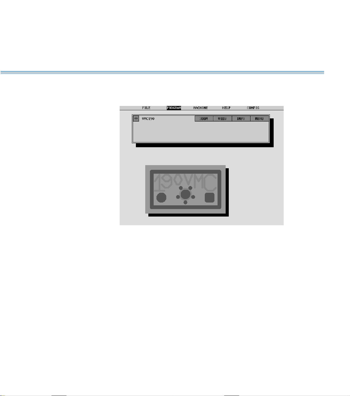
Boxford 190 VMC
2 Running the Demonstration Program
7. Select VMC 190
The screen shows the Program Display with a 2D view of the component.
Page 10
2 Running the Demonstration ProgramBoxford 190 VMC
View the Component
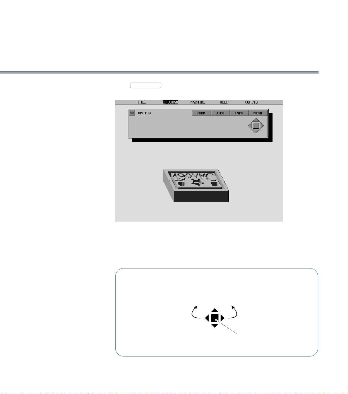
8. Select
VIEW
to produce a 3D view of the component. After a pause the display will
show the 3D view:
Manipulate the 3D view as follows:
Using a Mouse:
Click on the control buttons -
Rotate
clockwise
Increase
size
Decrease
size
Rotate
anticlockwise
Restore
original view
Page 11
Boxford 190 VMC
2 Running the Demonstration Program
Show the Program
Details
Using the Keyboard:
Rotate
clockwise
Increase
size
Decrease
size
Rotate
anticlockwise
HOME
Restore
original view
Note:
The time taken for the display to respond will depend on the speed of the PC and whether a co-processor
is fitted.
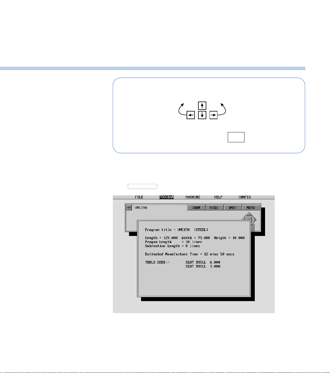
9. Select
INFO
to show the program details:
10. Turn off the program details display. (Click off the display window or press Return).
Page 12
2 Running the Demonstration ProgramBoxford 190 VMC
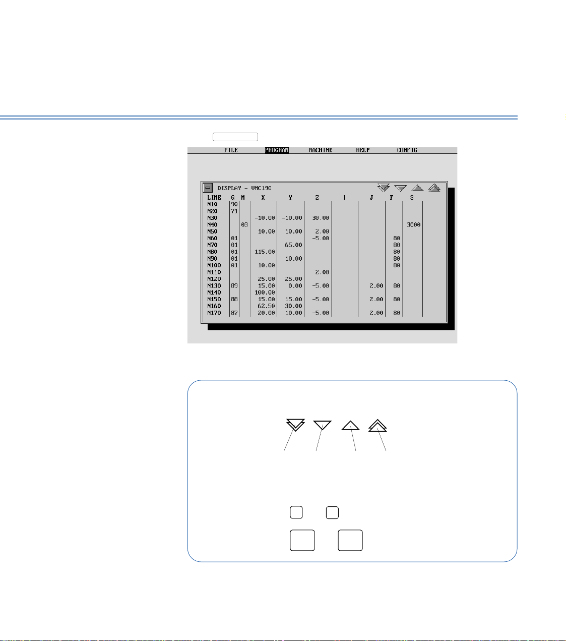
11. Select
MENU
and then Display:Display the Program
Scroll the display to examine the program:
Using a Mouse:
Click on the buttons
page
down
Using the Keyboard:
Press or to scroll 1 line
Page
Press or to scroll 1 page
12. Turn off the program display.
➔
up
1 line
down
1 lineuppage
up
➔
Page
down
Page 13

Boxford 190 VMC
2 Running the Demonstration Program
Zoom the Display
The ZOOM facility enables a rectangular area of the workpiece to be isolated and viewed
in greater detail for editing purposes. Full use of the facility is explained in Section 10 -
Manual Data Input CNC Programming, 10.8.3 - ZOOM Facility.
The following steps provide a brief demonstrations, returning to the display of the
complete workpiece.
13. Select
ZOOM
. The screen displays a 2D view of the workpiece with a menu bar at the
top, and sliders and arrow buttons arranged horizontally and vertically.
Explore the use of the REDUCE and ENLARGE options, and the sliders and arrow
buttons, to define a section of the workpiece with the rectangular selecting frame.
(RESET restores the frame to its original size).
14. Select
ACCEPT
. After a pause the screen shows the program EDIT display with a 3D
view of the selected area of the workpiece.
15. Select
ZOOM
, then Unzoom to restore the 3D view of the complete workpiece.
Page 14
2 Running the Demonstration ProgramBoxford 190 VMC
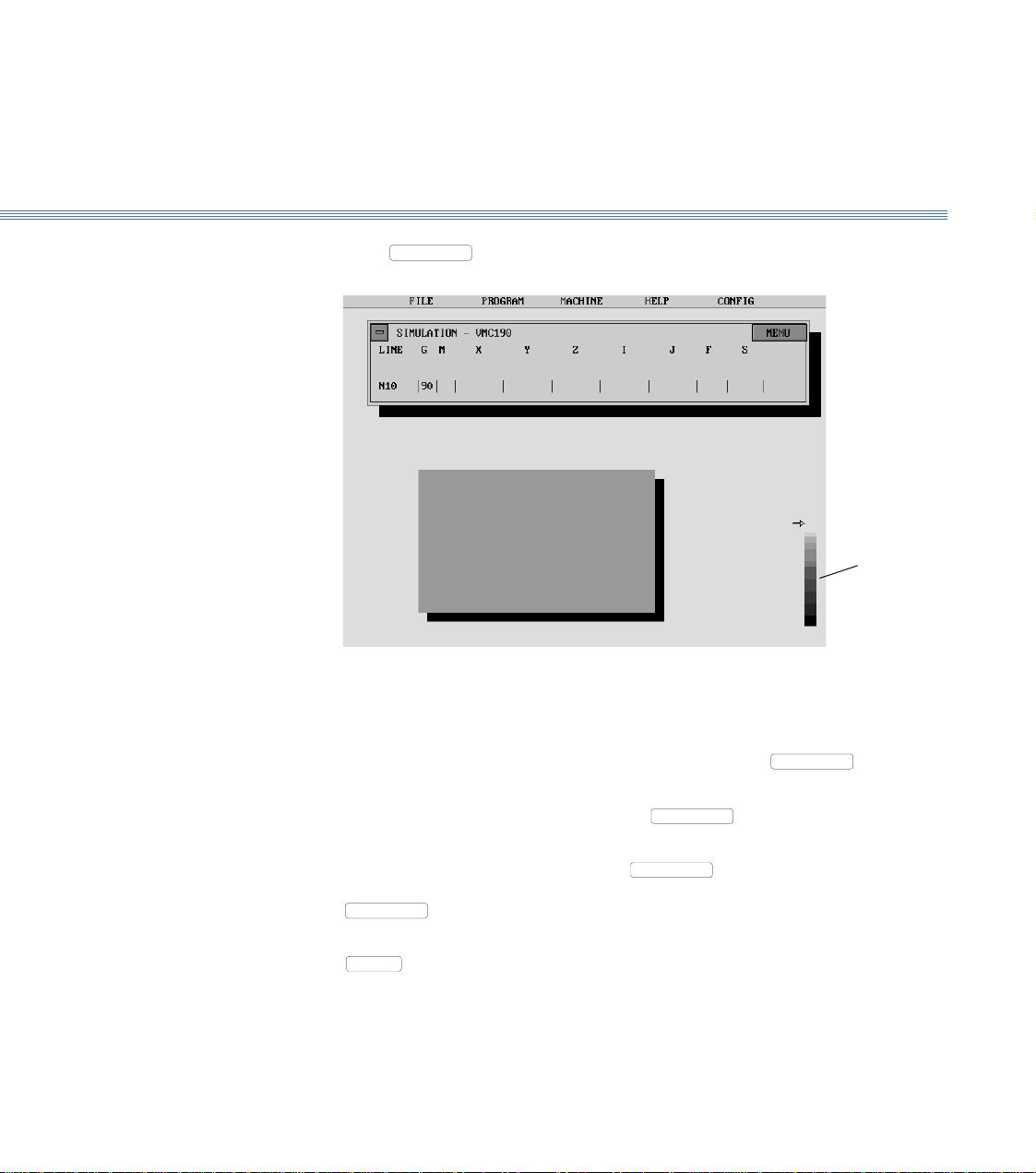
Simulate Machining
- 2D
16. Select
MENU
, then 2D Simulate:
Repeatedly click the mouse button or press Return to move through the program line-by-
line. The simulation shows the tool movement and metal removed as each line of the
program is executed.
To move forward through the program to a specific line, select
MENU
to Line. Type the required line number when prompted, and press Return.
tool
depth
display
, and then Go
To produce a 3D view of the workpiece, select
MENU
and then Solid View. To return
to the 2D view, click the mouse button or press Return.
To run the simulation automatically, select
MENU
and then Fast Mode; the program
will be run in a continuous sequence. To return to line-by-line simulation, select
MENU
and then Step Mode.
To end the simulation before the end of the program, click on the 'off' button or press
ESC
.
At the end of the program the screen returns to the program display.
Page 15

Boxford 190 VMC
2 Running the Demonstration Program
Simulate Machining
- 3D
Machine the
Component
17. Select
Select
MENU
MENU
, then 3D Simulate:
, and demonstrate the use of the options available as for the 2D
simulation, until the screen again shows the program display.
Refer to Section 11 - CNC and CAM Machining.
Page 16

Boxford 190 VMC
Axes and Tooling
3 Axes and Tooling
3.1 Fitting Tooling (Figure 3.1)
The cutting tool fits directly into a tool holder and is secured in position by a single
Allen screw.
The tool holder in turn fits into the machine spindle taper and is orientated by two dogs
which engage with the tool holder flange.
The tool holder pull stud is then drawn upwards by the spindle drawbar thus securing
the tool holder.
The drawbar can be manually operated by a lever on the side of the spindle or an
automatic tool changing device can be specified if required.
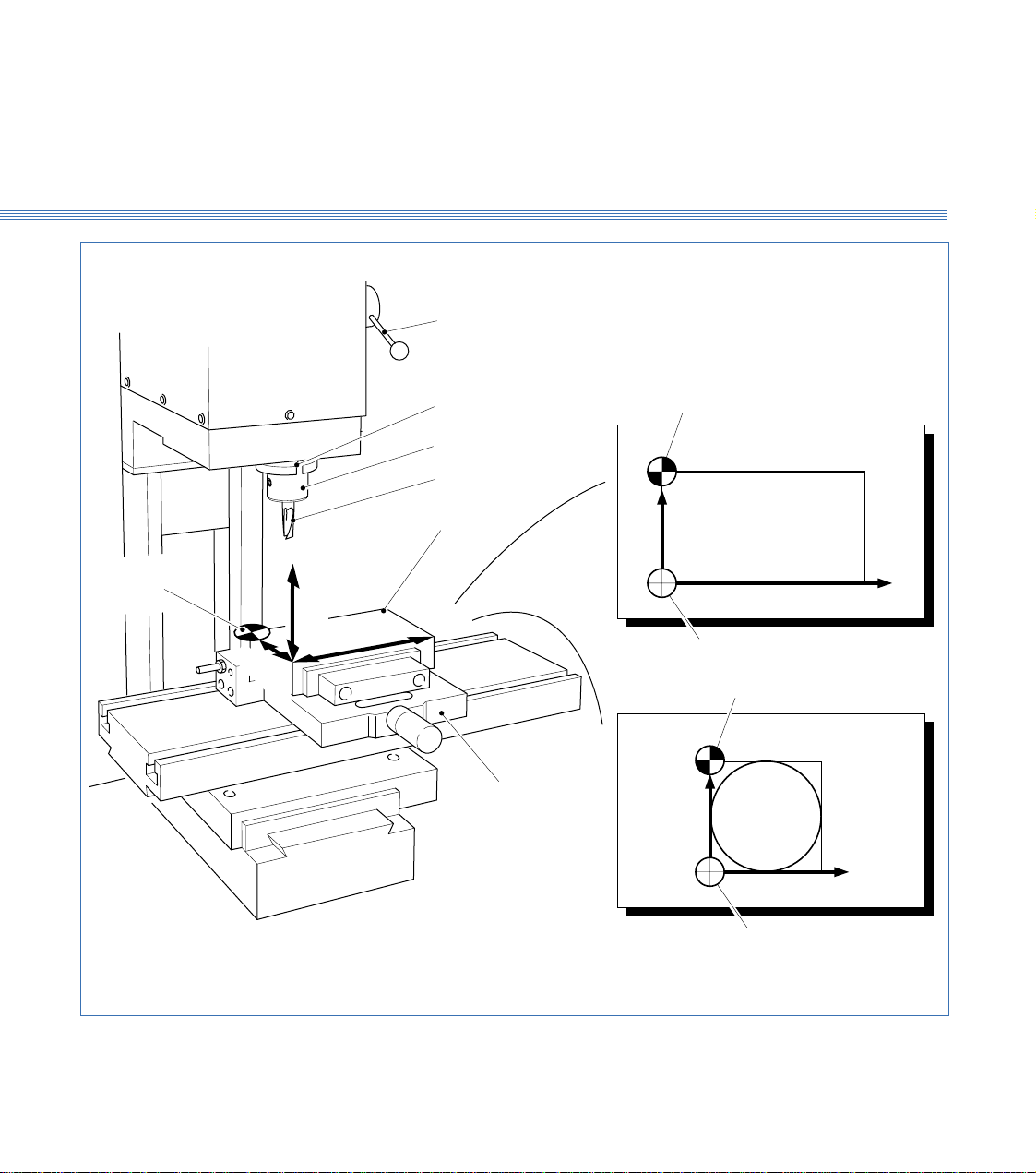
3.2 Axes, Datums and Offsets (Figure 3.1)
Axes
Datum Position
Figure 3.1 shows the movement of the tool in the X, Y and Z axes, in relation to the
billet. (In the X and Y axes the billet moves in relation to the tool, but for simplicity
and to conform with standard programming practice, it is the movement of the tool
in relation to the billet which must be considered).
On new machines, all Datum positions and Tool Offsets are set at the factory when tooling and clamping
is ordered with the machine.
The offsets of all required tools are set in relation to the machine Z datum.
Before any Tool Offsets can be set, the Machine Z Datum has to be defined.
From the machines Home Position, the Machine Z Datum is the measured distance from
the underside of the of the spindle head to the machine table top as shown in the diagram overleaf.
The X and Y Datum is the distance from the spindle centreline to a fixed point on the machine
table where the same corner of every workpiece locates to. (on a standard Vice, this is the imaginary
intersection of the vice rear jaw and the left hand end stop - a point where the Left Hand
corner of a workpiece locates to).
The datum position can be set to reference from Back Left, Back Right, Front Right
and Front Left corners of the workpiece (see section 3.5 - point 15 onwards for further
details).
Page 17
Boxford 190 VMC Axes and Tooling
Drawbar lever
3.1
DRAWING
Tool X,Y datum
Spindle
Tool holder
Cutting tool
Tool X,Y datum
+Y
Billet
Rectangular
billet
+X
+
Z
X
+
Drawing datum
Tool X,Y datum
Workholding vice
+Y
Circular
billet
-
+
Y
-
-
+X
Figure 3.1 Axes and Tool Datum
Drawing datum
Page 18

Boxford 190 VMC Axes and Tooling
3.2
Drawing Datum
Offsets
Dimensions on drawings are measured from the drawing datum. For convenience this
can be placed at the bottom left-hand corner of the billet and given X and Y co-
ordinates of zero. When a component is manufactured, the difference between the Y
co-ordinates of the tool and drawing datums is entered and the software compensates
for this difference.
The 190 software also allows the use of circular billets. For these, the X and Y datum
is usually at the bottom left hand corner of a square enclosing the billet.
Each tools offset is the distance from the Underside of the Spindle Head to the
tool end (bottom).
Underside of Head
Tool Z Offset
Machine Z Datum
Total Height of
Workpiece & Clamp
Machine Table Top
Page 19
Boxford 190 VMC Axes and Tooling
Tool rack
(basic 190VMC)
Spindle
3.2
Auto tool changer
Figure 3.2 Tool Storage
Carousel
To pressure gauge
Page 20

Boxford 190 VMC
3.3 Tool Storage (Figure 3.2)
3.3
Axes and Tooling
Tool Rack
(Figure 3.2)
Auto Tool Changer
(Figure 3.2)
Manual Operation
On the basic 190 VMC a tool rack is provided, as shown in Figure 3.2, to facilitate
storage of up to 5 tool holders and associated cutting tools.
It is advisable to store the tools in the same order as they will be called for in the
machining program.
Automatic tool changing equipment is supplied as an optional extra .
A carousel facilitates storage of up to 5 tool holders and associated cutting tools. Each
tool holder must be loaded into the correct carousel station so as to correspond with
the machining program prior to cycle start, i.e.:
Tool No.1 = Station No.1
Tool No.2 = Station No.2
The machine cycle start cannot be activated until the carousel has been indexed to Tool
No. 1, the reference tool station.
The auto tool changer is a pneumatic device requiring a compressed air supply of 80
lbf/in2.
Ensure therefore that the system pressure gauge reads 80 lbf/in2 prior to operating the
auto tool changer controls.
Pressing the Tool Change button on the main control panel will direct the auto tool
changer to remove the tool holder currently in the spindle, place it in the correct
carousel station, index the carousel to the next station, secure the next tool holder into
the spindle and retract.
Note:
When using the Tool Change button ensure that the spindle is at least 5mm below the upper Z+
limit of its travel.
Programming the Auto Tool
Changer
The CNC code for a tool change is the same as for a standard machine. Using the M
code M06 you must define the tool type e.g. type 2 (a slot drill), the diameter of the
tool and the station number 1 5 in the carousel, for example:
M06 I2 J6 F4
Where I = a slot drill
J = diameter of 6mm
F = station No. 4.
On completion of the part-program the machine will automatically change back to tool
1 allowing batch quantities to be machined.
Page 21
Boxford 190 VMC
3.4
Axes and Tooling
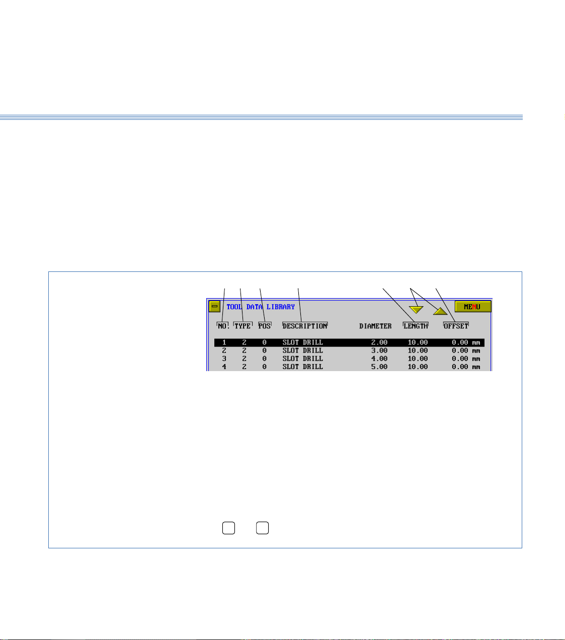
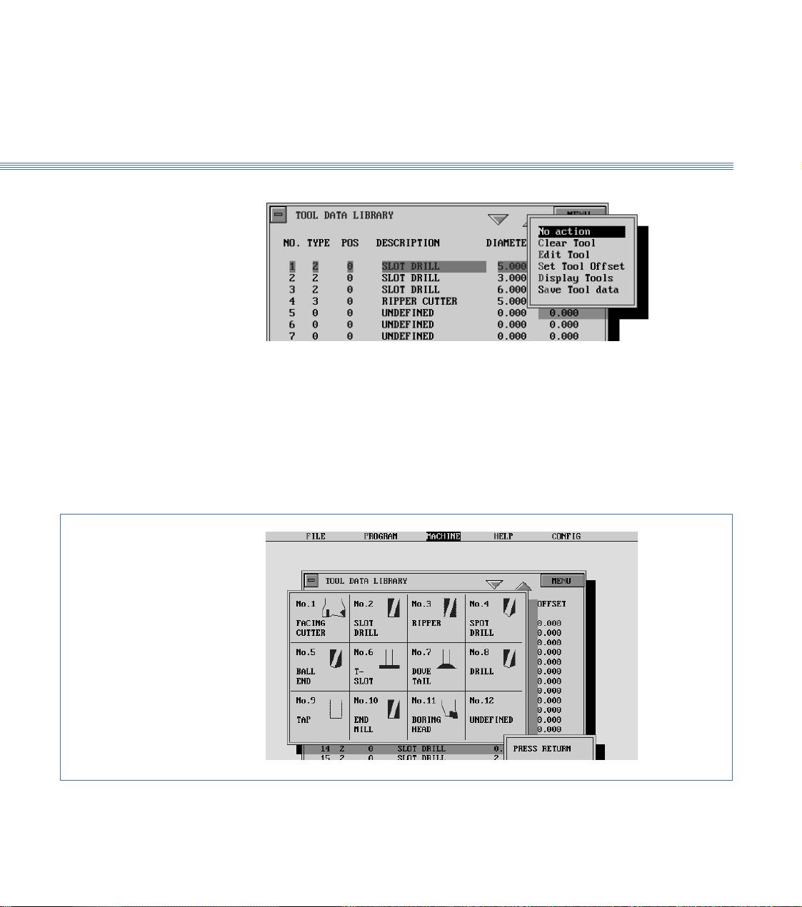
3.4 Tool Data Library and Catalogue
The 190 software provides a Tool Data Library which enables details of tooling and
offsets to be entered and a tool catalogue from which tools can be selected for inclusion
in the library. The library is set up by means of a tooling menu.
Before attempting to set up the tooling for the first time, view the library, the tooling
menu and the catalogue to become familiar with the details, as follows:
1. Switch on the PC, run the 190 Software.
2. From the main menu, select MACHINE and then Tools.
Tool Data Library
Details of selected tool are highlighted.
When the display first appears, the initial
tool is highlighted. Other tools can be
selected as shown below.
The screen shows the Tool Data Library, (Figure 3.3). Practice selecting tools using
the mouse and keyboard.
3412
1. Tool number used by CNC program to select
required tool
2. Tool type (selected from tool catalogue)
3. Tool station (carousel)
4. Tool description (selected from tool carousel)
567
5. Scroll buttons
6. Tool offset
7. Tool flute length
To select a tool:
Using a mouse
Click on the scroll buttons (6) to highlight the required tool.
Using the keyboard
Press ➔ or ➔ to highlight the required tool.
Figure 3.3 Tool Data Library
Page 22
Boxford 190 VMC Axes and Tooling
3.4
Tooling Menu
Tool Catalogue
3. Select MENU to display the tooling menu:
The use of these options for setting and editing the Tool Data Library is detailed later
in this section.
Note:
After setting up or editing the library, always select Save Tool data.
4. From the tooling menu, select Display Tools.
The screen shows the tool catalogue, (Figure 3.4).
Turn off the tool catalogue display to reveal the Tool Data Library.
Figure 3.4 Tool Catalogue
Page 23
Boxford 190 VMC Axes and Tooling
Spindle Carousel Direction
of rotation
Fit reference
tool here
3.5
3.5 Setting Up
Note:
A billet of the appropriate size will be required for this procedure. In order to run the demonstration
program, a 5mm slot drill and a 5mm end mill are required. To run the program, set up the slot drill
as the initial tool and the end mill as the second tool in the following procedure. If you want to fit a
different initial tool or second tool, substitute the tool details as appropriate.
Fit Initial Tool
Fit the billet into the workholder, then fit the tooling as detailed below:
1. Basic 190 VMC with Tool Rack
Fit the 5mm slot drill into the tool holder and secure the tool
holder into the spindle by operating the drawbar lever (Figure 3.1).
If the spindle is too close to the work holding vice to allow the tool to be fitted then
use the manual controls to move the spindle up until sufficiently clear. (See Section 12
- Manual Machining).
2. 190 VMC with Auto Tool Changer
Fit the 5mm slot drill into the tool holder and secure the tool holder into the carousel
as shown in Figure 3.5.
Ensure that the spindle is in the correct Z+ position to facilitate auto tool changing.
Press the TOOL CHANGE button on the control panel.
The carousel will then traverse left to the spindle position, perform the actions of
removing a tool holder from the spindle, index to the reference tool, load and secure
the reference tool into the spindle, and retract.
The reference tool is now fitted in the spindle.
Figure 3.5 190 VMC with Auto Tool Changer - Reference Tool Position
Page 24
Boxford 190 VMC Axes and Tooling
3.5
Configure Software
Set Initial Tool Offset
3. Check that the POWER ON RESET button on the machine control panel is lit.
4. Run the 190 Software. From the main menu select CONFIG and then Program.
5. Set the required values and turn off the display.
The screen shows:
6. Select YES
7. Select CONFIG and then Hardware. Make the required settings, turn off the display,
and save the settings.
The screen shows the Main Menu.
8. From the main menu, select MACHINE and then Tools to display the Tool Data
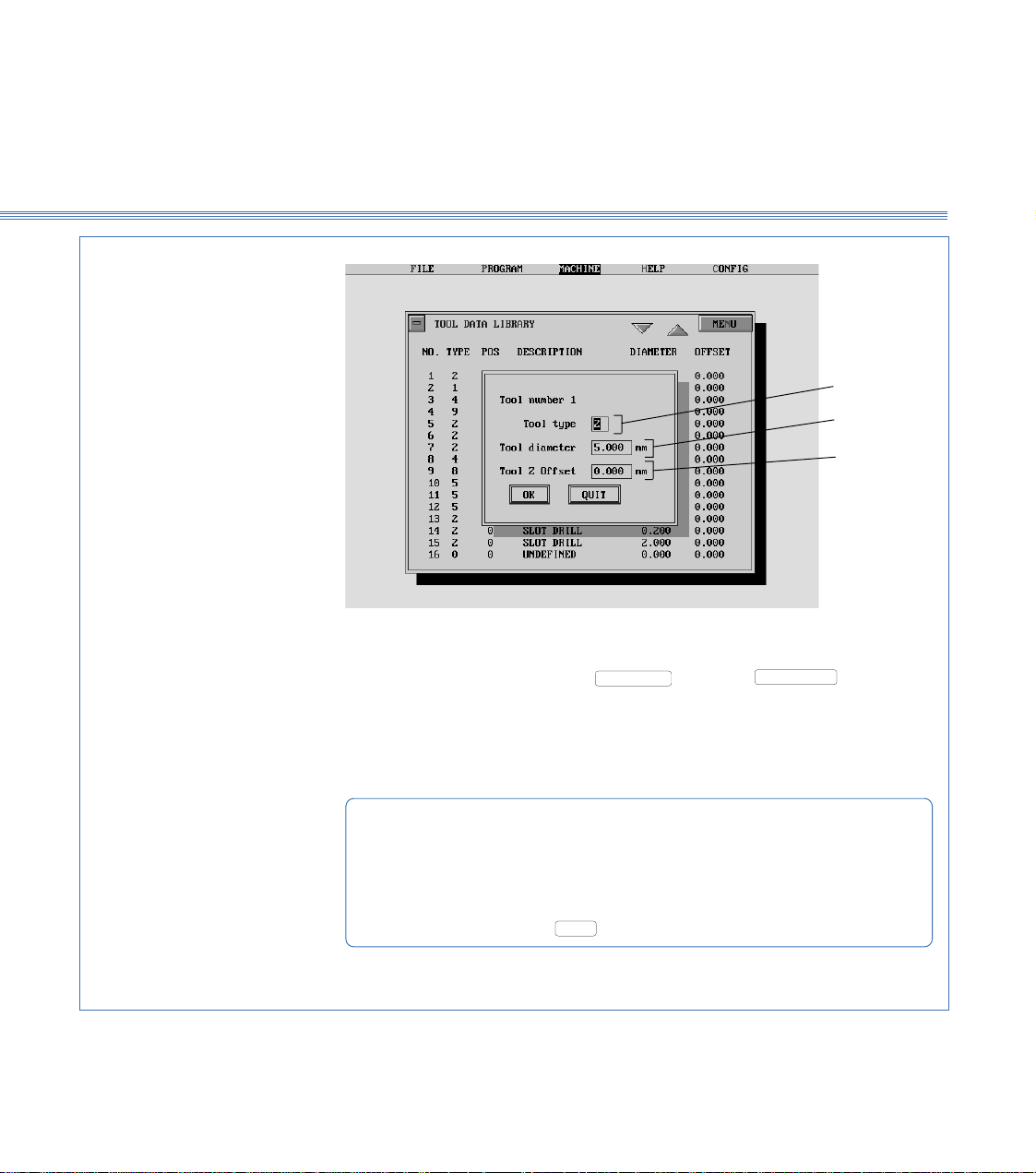
Library. The settings for the 5mm slot drill will be highlighted, for example:
Check the tool details (excluding the offset). If they are correct, continue at step 10 to
set the offset.
9. To edit the tool details, select
The screen shows the tool editing display, with the first item (Tool type) highlighted,
(Figure 3.6).
Edit the display to show the correct settings.
MENU
and then Edit tool.
Page 25
Boxford 190 VMC Axes and Tooling
QUIT
OK
3.5
1
2
3
1 To check tool type, press Escape or select
Display tools to view tool catalogue.
2 Diameter of slot drill is 5.00mm
3 Offset for reference tool is zero.
To edit tool details:
Type required number in highlighted box
Press Return to highlight next box
When last box is highlighted, press Return: highlight will disappear
Press Return or click on
Figure 3.6 Tool Editing Display
, then select
to turn off display
MENU
and
Page 26

Boxford 190 VMC Axes and Tooling
3.5
10. Select
If the touch-on point is to be the top of the billet, enter the height of the billet. If the
touch-on point is to be the base of the workholder, enter zero.
11. If the Software detects the machine is in Manual Mode, the user is prompted to
Cancel Manual Mode
The window below is shown.
MENU
, and then Set Tool Offset. The screen shows:
1. The machine RESET button is pressed.
2. a. The Z+ and Z- keys are pressed simultaneously (this axis must reach
home position before step b. can be started.
b. The X+ and X- keys are pressed simultaneously.
c. The Y+ and Y- keys are pressed simultaneously
2. ALTERNATIVELY, the F1 function key on the PC keyboard can be
pressed. This automatically performs steps a, b and c.
Page 27
Boxford 190 VMC Axes and Tooling
12. When the axes reach the home position, the screen shows:
On the machine control panel, select Manual mode. Using the axis control buttons,
touch the point of the tool on to the top of the billet.
3.5
Set Additional
Tool Offsets
13. When the tool is in the correct position, select
again shows the Tool Data Library.
If additional tool offsets are to be set, continue at step 14. If not, continue at step 15
to set the machine datum position.
14. To set the offset of the next tool, fit or index the tool and repeat the procedure from
step 8.
Note:
For setting the offsets of the second and any subsequent tools, it will not be necessary to enter the height
of the billet or to home the axes (steps 10 and 11).
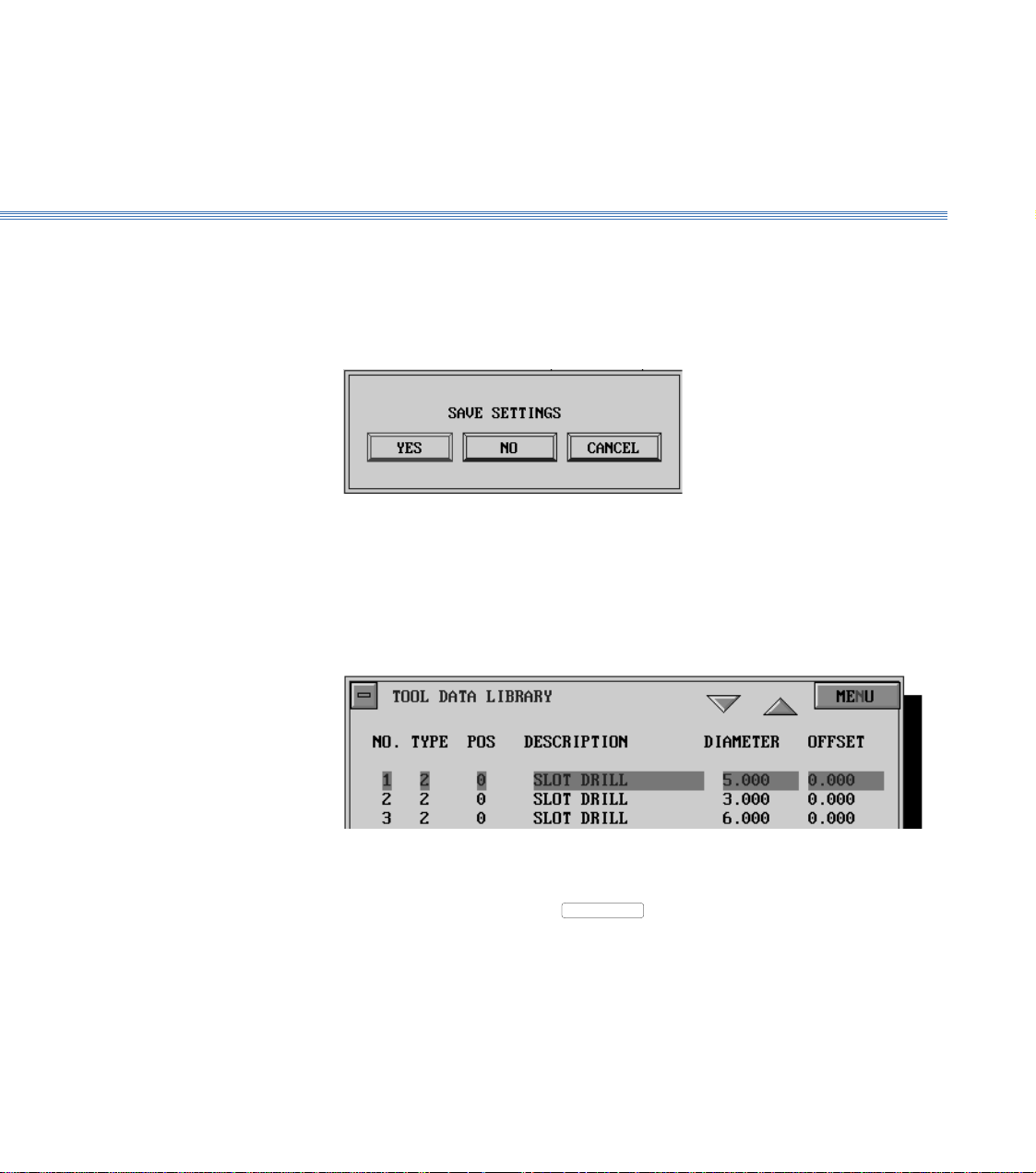
When the offsets of all the required tools have been set, either select
then Save Tool Data, or click the 'off' button of the Tool Data Library display. If the
'off' button is clicked, the screen shows the message:
Click on
or press Return to save the offsets.
YES
or press Return. The screen
EOB
MENU
and
Page 28
Boxford 190 VMC Axes and Tooling
3.5
Set Machine
Datum Position
Note
It is only necessary to set the datum position if the workholder position is changed or the Datum
position (back, front, left, right) is changed
15. There are now a number of additional Datum Position options.
Datum Position - Select CONFIG and then Hardware.
The window below is shown.
With the DATUM POSITION option highlighted, the options can be accessed
and selected using ALTER.
The datum position is:- a point on the machine table where the same corner of every workpiece
locates to.
e.g. On a VMC machine fitted with a standard Vice, the workpiece BACK face locates
to the fixed rear vice jaw and the workpiece LEFT face locates to the vice end stop
- hence the setting would be BACK LEFT
The Datum Position is selected and the settings saved.
From the main menu, select MACHINE and then Datum Position.
Page 29
Boxford 190 VMC Axes and Tooling
3.5
16. Select
SETUP
. The screen shows the Enter a Tool display:
17. Select a tool for which the offset has been set, (for example tool no. 1), and
select
ACCEPT
or press Return.
If the Software detects the machine is in Manual Mode, the user is prompted to
Cancel Manual Mode
The window below is shown.
1. The machine RESET button is pressed.
2. a. The Z+ and Z- keys are pressed simultaneously (this axis must reach
home position before step b. can be started.
b. The X+ and X- keys are pressed simultaneously.
c. The Y+ and Y- keys are pressed simultaneously
2. ALTERNATIVELY, the F1 function key on the PC keyboard can be
pressed. This automatically performs steps a, b and c.
Page 30
Boxford 190 VMC Axes and Tooling
3.5
18. When the axes reach the home position, the screen shows:
Measure the dimension (from the underside of the spindle head to the machine table
top), and enter the value. (This establishes the Z axis datum).
19. Select
OK
or press Return twice. The screen shows:
Note:
The Face of the billet to touch on will depend on the Datum Position setting in the Hardware
configuration - see point 15
On the machine control panel, press MAN to select Manual mode. Use the axis control
buttons to touch the side of the tool on to the left face of the billet. (This establishes
the X axis datum; the software compensates for the radius of the tool).
20. When the tool is in the correct position, select
ENTER
or press Return. The message
on the display now prompts you to touch on to the rear face of the workpiece with the
selected tool.
Using the axis control buttons, follow the instructions to establish the Y datum in the
same way as for the X datum.
Page 31

Boxford 190 VMC Axes and Tooling
3.6
21. When the tool is in the correct position, select
shows:
Click on
The screen returns to the main menu.
YES
or press Return to save the offsets.
ENTER
or press Return. The screen
3.6 DATUM SHIFT
Datum Shift is a new feature which allows the user to input a temporary shift of the
Datum Position for individual components which cannot be located to the standard
datum position.
To activate this facility, CONFIG followed by Hardware is selected. The Datum
Shift option is highlighted and ALTER followed by ON selected
To define default values, Machine followed by Datum Position is selected.
The window below is shown.
The default X and Y Datum Shift values are entered (the distance from the standard
datum position to the temporary datum position). These can be left at 0.00 and defined
when individual components are manufactured.
Page 32

4 Main Front End Menu
When the Boxford CADCAM package is started, the Main Front End Menu screen
below is shown.
This menu is the central manager of the CADCAM tools within the Boxford VMC
package.
G&M Program Import &
Administration Functions
Program Simulate, Manufacture
and Machine Tool Driver
CAD and CAM Processor Exit to Windows Desktop
Page 33

Boxford 190 VMC
4.1 Main Front End Menu
In Standard User mode this menu accesses the G&M code program import filter. (See
section 7.2)
In Administration mode (See section 8) additional CAM processor data settings can be
accessed and modified.
Accesses the Integrated Computer Aided Design package (See section 5) and CAM
processor (See section 6)
Also used to access CAD package to import drawing files (See section 7).
Accesses the G&M program Simulator, Editor, Writer and Machine Tool driver. All
the configurations for connecting the VMC machine to the PC are set in this section
of the package (See separate Installation & User Manual together with this manual).
Exits to the Windows desktop.
Page 34

Boxford 190 VMC CAD
5 CAD
5.1 CAD Window The CAD program window provides a clear view of the current drawing, various
information areas, and a selection of icons with tools to cover the most common
drawing, editing and display functions.
Allows the setting of
line type, thickness
and colour
Simple prompts tell
you what to do next
Toolbar help explains
each icon
Pull out sub-menu.
Select a toolbox icon
to reveal the menu
Relocatable draw/edit
toolbox allows easy
access to all the main
draw/edit functions
Absolute coordinates shows the position of
the cursor relative to the workpiece datum
(the bottom left hand corner)
Coordinate data entry
box allows accurate
positioning and
drawing at any time
Relocatable drawing
aids toolbox has a
range of commonly
used functions
Workpiece area
Shows the angle from
the last point located
or drawn
Help message bar
Shows the distance from the
last point located or drawn
Menu Selection Menu items are normally chosen from the menu bar or the toolbox, using the mouse
(although keyboard alternatives are available). To choose a menu item from the
toolbox, position the pointer over the appropriate icon and click the LH mouse button.
Some items such as Grid, will cause the icon to stay depressed until it is chosen again.
Many of the items in the LH toolbox have pull out toolbars.
Page 35

Boxford 190 VMC CAD
These are activated by positioning the pointer on the icon then clicking the LH mouse
button. The required icon can be selected from the icon menu bar. This will select
the item, and change the icon in the toolbar to that chosen. Most menu items, e.g., text,
colour fill, etc., have a related dialogue box for settings. To access these dialogue boxes,
double click on the appropriate icon with the LH mouse button, or click on the icon
with the RH mouse button.
Initial Set-up Before starting to use the CAD system, a number of Initial Set-up steps must be
completed. Select the Set-up menu and complete the following:-
1. UNITS - Specify Millimetres or Inches. More advanced settings for Angle units and
co-ordinate display are also available.
2. WORKPIECE - Specify the X (length) and Y (width) dimensions.
3. GRID and STEP - Specify the X and Y spacing for the Grid and Steps. (The Grid
is visible and the Steps are graduations between the Grid points).
5.1
4. SET AS DEFAULT - If you want the CAD system to default to settings 1, 2 and 3
each time you start a new workpiece, then select this option.
Page 36

Boxford 190 VMC CAD
5.2
5.2 Drawing Aids
Drawing Aids The right hand toolbox contains a number of drawing aids which are active when
selected (icon is dark grey).
Grid Display - Toggles the grid display on and off.
Redraw - Refreshes the screen.
Grid Lock - Locks the cursor movement to the grid spacing.
Step Lock - Locks the cursor movement to the step spacing.
Attach - Attaches the cursor to various points. Set-up can be accessed by Right clicking
on the Attach icon.:-
Radial Lock - Constrains cursor movement to pre-defined angle increments. Set-up can
be accessed by Right clicking on the icon.
Zoom In - Performs a quick and simple zoom in facility on the workpiece area currently
in the centre of the screen.
Zoom Out - Performs a quick and simple zoom out facility on the workpiece area
currently in the centre of the screen.
Undo/Redo Last -Toggles between undo and redo of the last function
Advanced Zooms These functions are available from the Left Hand Toolbox.
Zoom In - Zooms in on a user defined window.
Zoom Last - Reverts to the last specified zoom.
Zoom Sheet - Displays the complete workpiece at maximum zoom.
Zoom All - Displays all drawn entities at maximum zoom.
Zoom = - Zooms in by a user defined magnification factor
Page 37

Boxford 190 VMC CAD
5.3
5.3 Drawing Tools
Drawing Tools The left hand toolbox contains a variety of drawing tools and are grouped by the type
of entity they are used to define. To view the options within each group, LH Click on
an icon to display the full selection of group icons.
Co-ordinate Entry With all drawing tools that require points to be specified, these can either be defined
with the mouse (using the grid) or by co-ordinate entry.
To enter a co-ordinate, type the values in the co-ordinate data entry field (see section
5.1). These values can be Absolute (distance from the bottom left hand corner of the
workpiece) or Incremental/Relative (distance from the last point). To toggle between
Absolute and Incremental/Relative Modes, Select the Abs or Rel icon to the left of
the data entry field.
Help and Prompts Prompts and help for each icon are displayed on the toolbars to aid the user.
Straight Lines
Single Line - Defines a single straight line - The Start and End point are specified.
Circles
Connected Lines - Draws a series of connected lines - The initial Start Point and then the
subsequent End Points are defined. To finish, either double click the LH mouse button
(this will fix the moving line), or click the RH mouse button (this will finish at the last
fixed point).
Chamfer - Draws a chamfer between two lines - The chamfer X and Y dimensions are
entered and the two lines to be chamfered selected. To define a number of different
sized chamfers, RH click on the Icon to access the dimensions.
Circle - Draws a circle with a given Centre and Point - The circle centre and a point on
the circumference are specified (Note:- the Distance readout is equivalent to the circle
radius).
Circle - Draws a circle with a given Centre and Radius - The circle Radius is entered and
the centre specified. To define a number of different sized circles, RH click the Icon
to access the radius value.
Page 38

Boxford 190 VMC CAD
Circle - Draws a circle through 2 points - The two points on the circle circumference
and the centre point are specified. (Note:- the Distance readout is equivalent to the
circle radius).
Circle - Draws a circle through 2 points with given radius - The radius is entered, the
2 points on the circle circumference and the centre point position specified.
To define a number of different sized circles, RH click the Icon to access the radius
value.
Note :- If two points are specified through which it is impossible for a circle of the
specified radius to pass, the error message NOT POSSIBLE is displayed.
Circle - Draws a circle through 3 points - The 3 points on the circle circumference are
specified.
Arcs
Arc - Draws an arc with a given Centre, Start and End points - The centre, start and
end points are specified. (Note:- the Distance readout is equivalent to the arc radius).
5.3
Arc - Draws an arc through 2 points - 2 points on the arc and the centre point are
specified. (Note:- the Distance readout is equivalent to the arc radius).
Arc - Draws an arc through 2 points with a given radius - The radius is entered, Minor
or Major arc type selected and 2 points on the arc specified.
To define a number of different sized arcs, RH click the Icon to access the Radius and
Major/Minorvalues.
Note :- If two points are specified through which it is impossible for an arc of the
specified radius to pass, the error message NOT POSSIBLE is displayed.
Arc - Draws and arc through 3 points. - The 3 points on the arc are specified.
Page 39

Boxford 190 VMC CAD
Fillet - Draws a fillet between two lines - The radius dimension is entered and the two
lines to be chamfered selected. To define a number of different sized fillets, RH click
on the Icon to access the radius value.
Ellipse
Ellipse - Draws an ellipse - The centre and corner of the box surrounding the box is
specified (see diagram below).
Theoretical box Corner
surrounding ellipse
Centre
+
5.3
Shapes
Rectangle - Draws a horizontal rectangle - Opposite corners of the rectangle are
specified.
Rectangle - Draws a rectangle at any angle - Two points define the first side of the
rectangle (and its angle). The third point determines the length or width of the
rectangle.
Triangle - Draws a triangle at any angle - The 3 points of the triangle are defined.
Parallelogram - Draws a parallelogram at any angle - Two point define the first side of
the parallelogram (and its angle). The third point determines the angle and length of
the opposite sides.
Page 40

Boxford 190 VMC CAD
5.3
Polygon - Draws a regular polygon with a given centre and vertex - The number of sides
is entered via the dialogue box below. The start angle can be entered at this point or
defined later. Clockwise or Anti-clockwise orientation of the angle can be specified.
The side length or Internal Radius or External Radius can also be specified
Internal Radius
Side
Length
OK
is selected and the centre point specified. If necessary, the external radius is
+
External
Radius
Start
Angle
set by specifying a second point.
Polygon - Draws a regular polygon with a given internal radius and centre. The Start
Angle can be entered at this point or defined later. Clockwise or Anticlockwise
orientation of the angle can be specified. The Internal Radius is specified.
is selected and the centre point specified.
OK
Page 41

Boxford 190 VMC CAD
Beziers
Open Bezier - Draws an open ended bezier curve - The initial Start Point and then the
subsequent End Points are defined. To finish, either double click the LH mouse button
(this will fix the moving bezier), or click the RH mouse button (this will finish at the
last fixed point).
Closed Bezier - Draws a closed bezier curve - The initial Start Point and then the
subsequent End Points are defined. To finish, and close the path either double click
the LH mouse button, or click the RH mouse button.
Open Polyline - Draws an open polyline (series of connected straight lines). The initial
Start Point and then the subsequent End Points are defined. To finish, either double
click the LH mouse button, or click the RH mouse button.
Note :- An Open Polyline differs from a series of connected straight lines because
when complete the lines are part of a single object).
Closed Polyline - Draws a closed polyline (series of connected straight lines. To finish,
and close the path either double click the LH mouse button, or click the RH mouse
button.
5.3
Text Strings
Text - Defines Linear Text strings - The start point is located bringing up the
dialogue box shown below.
At the prompt the required text is typed and selected.
Settings
Page 42

Boxford 190 VMC CAD
5.3
The dialogue box below is shown.
Font
The font type can be selected from the list of all the True Type fonts available on the
system. Font styles can also be selected.
Size
The font height can be selected (this is very easy to manipulate later - see Editing
Objects in section 5.4 for further details).
Alignment
The alignment from the previously defined start position can be set to Left, Right or
Cantered.
Attributes
The Line Type, Line Colour, Fill Type and Fill Colour can all be set. The default setting
is filled text with a thin outline. The relevance of these settings with regard to
machining is covered in section 5.6 (CAD Machining Considerations).
Once all the settings are correct, select The previous input box is displayed.
Select The text object appears on the workpiece.
OK
OK
Page 43

Boxford 190 VMC CAD
5.4
5.4 Editing Objects
Selecting Objects
Select - Objects can be selected by :-
1. Dragging a box around the objects to be selected.
2. Selecting Individual Objects with the LH mouse button and subsequent objects
(if required) with the RH mouse button (or SHIFT + LH button).
Once an object or group of objects are selected, the selected objects are drawn in pink
and surrounded by a dotted box (a marquee box) with handles. This is shown below.
These handles provide quick edit functions. For more advanced features, see
Transformations described later in this section.
Re-Size Re-Size Re-Size
Mirror Horizontally
Re-Position
(move)
Re-Size
Mirror
Vertically
Re-Size
Copy
Re-Size Re-Size Re-Size
Rotate
Re-Sizing
LH mouse clicking any square handle around the outside of the marquee box allows
the current selection to be re-sized. Clicking again redraws the selection to the new
specification.
Warning:- moving these handles alters the aspect ratio of the current selection. To re-
size whilst maintaining aspect ratio, select the square handles with the RH mouse
button.
Page 44

Boxford 190 VMC CAD
Re-Positioning (Moving) LH clicking on the central square handle allows the current selection to be moved.
Clicking again redraws the selection in the new position.
Mirroring The diamond (rhombic) handles, to the top and left, mirror the current selection
horizontally and vertically respectively.
Rotating The circular handle to the right allows the current selection to be rotated.
Copying The double square handle at the bottom performs a quick copy and paste of the current
selection, leaving the new object selected.
Editing Objects
When a selection is made, a toolbox appears in the right hand corner of the CAD
window. Selecting Start Edit greys the selection and provides a number of coloured
edit handles as shown below.
5.4
Page 45

Boxford 190 VMC CAD
The convention of these handle colours depends on the object selected and are
generally as follows.
Line Green = Start Node, Red = End Node - Each can be re-positioned.
Circles Red = Node on Circumference, Yellow = Centre Node - Each can be repositioned.
Arcs Green = Start Node, Red = End Node, Yellow = Centre Node - Each can be re-
positioned.
5.4
Closed Polylines
(including Shapes)
Open Polylines Green = Start Node, Red = End Node, Orange = Intermediate Nodes - Each can be
Closed Bezier Curves Red = Start and Finish Node, Orange = Intermediate Nodes, Yellow = Node Handles
Open Bezier Curves Green = Start Node, Red = End Node, Orange = Intermediate Nodes, Yellow = Node
Text Yellow = Bottom left hand corner of imaginary rectangular box enclosing each
Red = Start and Finish Node, Orange = Intermediate Nodes - Each can be re-
positioned.
re-positioned.
- Each can be re-positioned individually. Additionally, moving the yellow node handles
with the RH mouse button locks the angle between them allowing them to move
together
Handles - Movement as per Closed Beziers.
individual character. - Each character can be re-positioned.
Page 46

Boxford 190 VMC CAD
Transforming Objects Selected objects can be transformed using a variety of tools :-
Move/Copy - Moves, and/or copies the current selection. The user can opt to replace
the current selection or create a user-defined number of repeats. A reference point
(usually on the selected object) is located and then a new position for the reference
point. An example of a repeat Move/Copy is shown below.
5.4
Mirror - Mirrors the current selection. The user can opt to replace the current selection
or repeat it. Two defined points define the axis of reflection. An example of a repeat
Mirror is shown below.
Rotate - Rotates the current selection. The user defines the angle of rotation and can
opt to replace the current selection or create a user-defined number of repeats.
An example of repeat Rotate is shown below.
Page 47

Boxford 190 VMC CAD
Rectangular Array - Produces a grid of selected object copies. The number of columns
and rows and the X and Y spacing between them are specified. An example is shown
below.
Circular Array - Produces rotated copies of selected objects. The angle of rotation and
number of repeats are specified. The centre of rotation is defined. An example is
shown below.
5.4
Distort - Distorts the currently selected objects. The user can opt to replace the current
selection or create a user-defined number of repeats. The selected objects are
surrounded by a greyed outline with 4 handles. Re-positioning the handles and clicking
away from the selection will produce a distorted object which best fits the new handle
positions. An example of a replaced distort is shown below.
Page 48

Boxford 190 VMC CAD
Deleting Objects There are a number of ways to delete objects using either icons from the toolboxes or
Hot Key combinations.
Delete Last - Deletes objects one at a time in the order they were drawn (most recent
first).
Delete Any - Deletes individual entities - A hand pointer is provided to select the
individual objects to be deleted.
Delete Inside Box - Deletes entities within a user defined box (by dragging).
Delete Part of Entity Between two nearest intersections - Automatically trims a line back to the
nearest intersection. A hand pointer is provided to select the part of the entity to be
deleted. An example of tool use is shown below.
Before After
5.4
Useful Delete Hot Keys
Ctrl + Del - Deletes the current selection.
Ctrl + Backspace - Deletes the last drawn entities.
Alt + Del - Deletes all drawing entities.
Page 49

Boxford 190 VMC CAD
5.4
Setting/Editing
Object Attributes
Line Thickness From the top of the CAD window select
The attribute of an object (entity) defines the way it is machined. For details see section
5.6 (Machining Considerations).
Object attributes can be set before they are drawn, or the current selection can be edited
in the following way:-
The dialogue box below is shown.
The user can define:-
Line Type - continuous, dotted, dashes etc.
Line Pitch - the pitch of dotted and dashed lines
Width - Either Fine or Thick (with a user defined thickness).
Page 50

Boxford 190 VMC CAD
Line Colour From the top of the CAD window select
The dialogue box below is shown.
5.4
Text
Warning - Choose only colours from the custom Pallet (the reason for this is explained
in Section 5.6)
is selected.
OK
When a Text selection is made, a toolbox appears in the right hand corner of the CAD
window. Selecting Property brings up the text input box. The Text string, Font,
Effects, Line and Fill properties can all de redefined. See Text Strings in section 5.3 for
more details.
Page 51

Boxford 190 VMC CAD
5.5
5.5 Area Filling
Area Filling One of the most important Tools to understand is colour filling as this largely dictates
what is actually machined (see Section 5.6 for more details on machining considerations).
Area - Fills areas between closed boundaries, accounting for islands.
On selecting the area tool, the following dialogue box is shown.
is selected bringing up the colour selection dialogue box.
Warning:- As with line colour settings, choose only colours from the custom Pallet (the reason
for this is explained in Section 5.6).
is selected.
OK
The user is prompted to:-
1. Locate on edge of boundary on side for hatch - This is the outer boundary of the fill.
In the example shown below, if the area between the 2 circles is to be filled, the larger
circle is the outer boundary. The boundary is located with the hand pointer.
Outer Boundary
Island
Page 52

Boxford 190 VMC CAD
5.5
2. The user is asked if there are any islands within the outer boundary.
Looking at the example on the previous page, the smaller circle is an island within the
larger circle.
is selected and the Island located with the Hand Pointer.
YES
The window above is shown again allowing further islands to be defined. In this
example there are no more. is selected.
NO
The area is filled.
Outer Boundary
Filled Area
Island
Note:- If a number of filled areas are to be defined, the colour can be redefined by RH
clicking the fill icon.
Page 53
Boxford 190 VMC CAD
5.5
Text Strings Text strings can be filled by setting the fill attribute when the string is initially defined
(see 5.3), or by selecting Property (see 5.4) when the string is selected.
Text strings can also be islands within a closed outer boundary. In this case, some
characters constitute more than one island as shown below.
Outer
Boundary Islands
If the 2nd Island was not specified, the fill would be as diagram b below instead of the
required fill shown in diagram a.
a. Correct b.Incorrect
Page 54

Boxford 190 VMC CAD
5.6
5.6 Machining Considerations
Machining Considerations Sections 5.1 - 5.5 have concentrated on the drawing tools within the CAD system.
Some important machining considerations relating to the drawing will now be
discussed.
Colours Sixteen custom colours are available in the colour palette dialogue box. When the
drawing is Post Processed into a G&M code CNC programme, each colour can be
assigned a different depth.
At the Design Stage, all the user must consider is that any objects required to
be cut to a different depth, MUST be assigned a different colour (up to a
maximum of 16 colours).
Machined Objects Objects that are machined are :-
1. Lines with a width setting (not thin lines)
2. Filled Areas
Lines Any line with a width setting (other than thin) will be followed with a Slot Drill of the
equivalent diameter or the nearest one available from the Machine Tool Library (See
section 8 for more details).
Filled Areas Any areas filled with colour can be:-
a. Pocketed out with a variety of tools - (cutter diameter compensation is
automatically implemented)
b. Profiled - around the outside (e.g. for cutting out a shape).
c. Profiled - around the inside (e.g. for leaving a cut-out of the shape in a sheet
of material).
Additionally filled circles can be:-
a. Pocketed out with a variety of tools - or
b. Drilled with a drilling cycle using a drill of the equivalent diameter or
the nearest one available from the Machine Tool Library (See section 8).
Page 55

Boxford 190 VMC CAD
Problem Objects With the large variety of drawing tools available, it is important to understand:-
a: What can and what can not be machined.
b: What will be machined.
What cant be machined 1. Lines with a width narrower than the smallest diameter Slot Drill will
not be machined.
2. Filled Circles with a diameter smaller than the smallest diameter Drill
Filled areas which have sections narrower than the Edging Tool (see
section 8 for details of edging tool). This often happens when the pocket
is the internal fill of some fonts as shown below. The circles within the
text represent where the cutter diameter can machine up to.
Notice the difference between what was drawn and what will be machined.
Drawn Text Machined Text
5.6
Warning :- If you draw text too small none of it may be machined. Please
remember you are cutting resistant materials and not merely dropping ink onto
paper.
Page 56

Boxford 190 VMC CAD
5.6
What will be machined As described in the previous section, the system will attempt to machine EVERY Line
with a width setting and Filled Area.
For this reason it is important that Islands are correctly defined. If a filled object (1)
is on top of another filled object (2). object (2) will still be machined even though it
cannot be seen on the screen.
In the example below object (1) has been drawn on top of the solid filled (no Islands)
object (2). If object (1) is to be machined to a depth less than object (2) then it will be
machined away when object (2) is machined.
Overlaid Objects Objects When Seperated
11
22
Machining Order The objects will be machined on an individual basis working from the back of the
drawing (i.e. the back object is machined first and the front object last).
This can be useful if for instance an object is to be profiled (cut out) as the last operation.
Page 57

Boxford 190 VMC 6.1 CAM Processor
6 CAM Processor
6.1 Settings
When the CAD drawing is complete and ready to be processed into a G&M code
CNC programme, select
The user is required to enter a filename for the drawing (Please ensure this is no
longer than 8 characters).
The CAM Processor Dialogue box shown below is displayed.
File To Mill
Material
The various settings are as follows:-
Selecting the drop down provides a list of the available material types. (See Section
8 - Administrator Mode for details on adding user defined materials and cut data.).
The required material is selected from the list
Page 58

Boxford 190 VMC 6.1 CAM Processor
Edging Tool and Area Tool The drop down for these two tools is a list of the slot drills available in the
Machine Tool Library.
The Edging and Area tool are used to remove (pocket) all Colour Filled areas in
the drawing. There function is as follows.
Edging Tool - This tool performs the finish path around the pocket as shown
with the circular object below
The edging tool is also used to profile around a colour which has been set to
Outside or Inside (see DEPTHS later in this section).
Area Tool - This (usually larger) tool is used to remove the bulk of material from
filled areas as shown with the circular pocket below.
Page 59

Boxford 190 VMC 6.1 CAM Processor
Warning To ensure filled areas are correctly removed, it is strongly recommended
that the ratio between the Edging Tool and The Area tool is 1:2 (e.g. 2mm
Edging Tool & 4mm Area Tool).
It is permissible to set the Area and Edging Tools to be the same diameter to avoid
tool changes during manufacture. Experienced users can experiment with different
combinations for different drawing applications.
Edging & Area Finish Determines the Surface finish produced by the
Edging and Area Tools. Smooth or Coarse is
selected.
Block Size The X (Length) and Y (Width) dimensions are transferred from the drawing. The
user must specify the Z (height or thickness) dimension.
Depths The Colour Depth and Filled area settings are accessed by selecting
The dialogue box below is shown.
Page 60

Boxford 190 VMC 6.1 CAM Processor
For each colour used in the drawing (the others are ignored), the total required
depth is entered. This can include decimal values (2 Decimal places in Metric and
3 Decimal places in imperial). There are 16 colours available which match the 16
custom colours in the CAD colour palette. Hence 16 different depths can be
defined.
Warning If the user defines a depth which can not be achieved by the current tools in the
machine library, the user will be warned upon processing the drawing (see section
6.2 - Error Messages).
To the left of each colour is a drop down menu. These settings affect ONLY
COLOUR FILLED AREAS and not lines with a defined width.
AREA Pockets out all areas with this colour fill with the Area and Edging tools as
described earlier in this section (Edging Tool and Area Tool).
DRILL Uses a drilling cycle to drill circles with a drill of equivalent diameter or the nearest
one (always smaller) available from the machine tool library.
The system will first look for a twist drill of appropriate diameter. If one is not
available, it will look for a spot drill and then a slot drill.
Warning Only colours made up entirely of individually filled circles should be assigned as a
DRILL colour.
Page 61

Boxford 190 VMC 6.1 CAM Processor
INSIDE Profiles around the inside of colour filled pockets using the Edging Tool.
Compensation for the diameter is automatically implemented. This can be
particularly useful when cutting profiles out of thin sheet material.
An example is shown below.
OUTSIDE Profiles around the outside of colour filled pockets using the Edging Tool.
Compensation for the diameter is automatically implemented.
An example is shown below.
When all the Colour Depths and Area Setting are complete, is selected.
OK
Page 62

Boxford 190 VMC 6.1 CAM Processor
Processing To process the Drawing and create a G&M CNC programme, is
selected. The message below is displayed
Selecting saves the CAM processor settings with the drawing.
YES
The processor analyses the Drawing and produces a G&M code CNC programme specifying
Cutter Paths, Speeds, Feeds and Cut Depths appropriate to the material type selected and the
tooling available.
The following message is displayed.
Factors Affecting Processing There are a number of factors which will affect the processing time.
1. Pocketing out complicated areas (particularly text strings) will increase
processing time.
2. Processing lines with a defined Width will be relatively quick.
3. The higher specification the PC Computers Main Processor the quicker
processing will be.
4. If the user has accidentally specified an unusually deep pocket, processing
time will be significantly increased. If you suspect a mistake, press the ESC
key on the keyboard to abort processing.
Page 63

Boxford 190 VMC 6.1 CAM Processor
Tool Path Simulation When the drawing has been processed the following dialogue box will be displayed
(Please note if processing reveals any errors this dialogue box will be proceeded by
an error message dialogue box - see section 6.2 for details).
The user is prompted to select a Catalogue number to place the file into.
Catalogues - All manufacture programs (G&M
programs) are filed in Catalogues. There are 9
catalogues available to the user.
A catalogue is selected. If a file of the same
2
1
9
8
7
6
5
4
3
name already exists in the selected catalogue,
the following dialogue box appears.
The file can be overwritten by selecting or can be selected bringing up
YES
NO
the following dialogue box.
The filename can be changed and/or the catalogue changed. is selected.
OK
Page 64

Boxford 190 VMC 6.1 CAM Processor
A 2 Dimensional simulation of the cutter path is shown. This is the final user
check of the component that will Actually Be Machined. Any areas which can
not be removed because of tooling limitations will be omitted. (see section 5.6 for
more details)
Warning :- Please check this 2 Dimensional View very carefully.
3 Dimensional View For details on 3D Views, View Manipulation and Cycle Details see sections 2 and
10.
Page 65

Boxford 190 VMC 6.1 CAM Processor
2
6.2 CAM Processor Error Messages
When Processing a drawing, the CAM processor compares the drawing
requirements with the Cutting Tools available. If any drawing requirements can
not be satisfied, then an error message (or messages) is displayed.
An example is shown below.
The user can continue processing by selecting
A program with the compromised settings (safe) is produced.
or
The user can abort processing by selecting and reprocess the drawing
using different settings.
Error Messages There are a number of error messages which can be reported. Their description
and causes are as follows:-
Cut Depth - The Cut Depth (Total - not cut per pass) will never exceed the Tool
Length value defined in the tool library (see Section 8 for more details)
e.g. 2.0mm slot drill is unable to cut deeper than 10.000mm
Cutter Diameter - If a Tool from the Tool Library cannot match a line with
defined width, or a drilled hole with defined diameter, the processor will choose
the nearest smaller diameter tool.
e.g. 8.0mm drill was not found, using 6.0mm instead
If a line width or hole diameter less than the smallest tool are specified, the objects
will not be machined.
e.g. could not find a drill 1.5mm or less
Page 66

Boxford 190 VMC 7.1 File Imports
7 File Imports
7.1 Drawing File Import
File Types The following drawing file types can be imported.
1 Design Tools Files (*.dtd)
2 Acorn Draw Files (*.aff)
3 Designer V3 COMMS Files (*.dv3)
4 DXF Files (*.dxf)
5 Enhanced Metafiles (*.emf)
6 Windows Metafiles (*.wmf)
File Export Rules Which ever drawing package you export from, there are some guidelines which will
help you to successfully export files suitable for importing into the Boxford
CADCAM package.
Drawing Size - Set the drawing size (or custom paper size) to the Workpiece size
you intend to use.
Drawing Origin - Set the drawing Origin to be the Bottom Left corner of the
Drawing (paper) area.
Length
Width
Line Width - Unless you can accurately set line widths to a specified value, do not
export lines with a width. Line width attributes can be set in the Boxford
CADCAM package after importing.
Filled Areas - DO NOT export any colour filled areas. Colour filled areas are
assigned in the Boxford CADCAM package after importing.
Dimension Lines - DO NOT export any Dimension Lines.
Drawing Area
(Paper Size)
Drawing Origin
Page 67

Boxford 190 VMC 7.1 File Imports
Importing Drawing Files The CAD Icon is selected from the Boxford CADCAM package.
CAD Icon
Workpiece Size - The workpiece size is set-up to suit the file intended for import.
(this should be equivalent to the Drawing Area/Paper Size used to create the
original file).
File
Import File
is selected bringing up the dialogue box shown below. The file
type is selected from the drop down menu.
Page 68

Boxford 190 VMC 7.1 File Imports
The file to be imported is located and selected
Open
Import Filters The various import filters have differing import options, described as follows:
1 Design Tools Files (*.dtd)
Opens a Techsoft 2D Design Tools File.
3 Designer V3 COMMS Files (*.dv3)
Opens the file automatically (no user settings are required).
2 Acorn Draw Files (*.aff)
5 Enhanced Metafiles (*.emf)
6 Windows Metafiles (*.wmf)
On opening any of these file types, the following dialogue box appears.
The options are:-
Centre In Window - Centres the imported drawing entities in the centre of the
workpiece. Not selecting this option will maintain the relationship between the
drawn entities and the origin.
In Window
= =Centre
=
=
Imported Entities Workpiece
Page 69

Boxford 190 VMC 7.1 File Imports
Group - Loads the imported entities as a single grouped object.
Scale - Scales the imported entities by a user defined value.
4 DXF Files (*.dxf)
On opening a DXF file the following dialogue box appears.
The options are:-
Interpret Units and Position - Allows the import units to be specified and
maintains the relationship between the drawn entities and the origin.
The Units Interpretation and Position options are:-
Inch or mm - set to suit the file to be imported
Centre in Window - Centres the imported drawing entities in the centre of the
workpiece (see previous page for details)
Scale - Scales the imported entities by a user defined value.
Page 70

Boxford 190 VMC 7.1 File Imports
Fit to Media - Scales the imported entities to fit the workpiece whilst maintaining
the aspect ratio.
The scaling factor is limited by the first axis the entities fill (X or Y).
In the example below, the scaling is limited by the workpiece width (Y axis) and
the entities centred along the length (X axis).
Fit To
Media
= =
Width (Y)
Imported Entities Workpiece
Length (X)
Load as Group - Loads the imported entities as a single grouped object
Dimensioning preference - Ignore these options - DO NOT attempt to
import dimensions.
Processing Imported Files Once imported, individual entity attributes and colour filled areas can be specified
as described in Section 5.
The drawing is processed as normal, see Section 6 for details.
Page 71

Boxford 190 VMC 7.1 File Imports
2
7.2 G&M Code Programme Impor t
The following procedure imports a G&M code program produced on a Third
Party CADCAM package.
From the main front end menu is selected followed by
From the File Open dialogue box, the file to be opened is selected.
The dialogue box below is shown.
The user is prompted to select a Catalogue number to place the file into.
All manufacture programs (G&M programs) are filed in Catalogues. There are 9
catalogues available to the user.
A catalogue is selected. If a file of the same name already exists in the selected
catalogue, the following dialogue box appears.
The file can be overwritten by selecting or can be selected bringing up
the following dialogue box.
The filename can be changed and/or the catalogue changed. is selected.
YES
NO
OK
Page 72

Boxford 190 VMC 7.1 File Imports
A 2 Dimensional simulation of the cutter path is shown.
This simulation does not have to be completed. Pressing the ESC key will stop
the simulation and write the file to disc ready for manufacturing.
Manufacture For details on Manufacturing see section 11.
File Import Specification The required Import file specification is as per the following example.
2
G71
G101 X125.000 Y75.000 Z10.000
G00 X0.000 Y0.000 Z20.000
M05
M06 I2 J4
M03 S3000
G00 X61.875 Y38.403 Z2.000
G01 Z-1.000 F600.000
...
G01 X56.422 F600.000
G00 Z2.000
G00 Z20.000
G00 X0.000 Y0.000
M05
M06 I2 J2
M03 S3000
G00 X56.422 Y37.602 Z2.000
G00 X62.909 Y38.194
G01 Z-1.000 F600.000
...
G01 X62.909 Y38.194 F600.000
G00 Z2.000
G00 Z20.000
G00 X0.000 Y0.000
M05
M30
Units
Workpiece Size
X, Y, Z Park Position
Spindle Stop
I=Tool Dia. J=Type
Start Spindle S=RPM
Body of Program
G00 and G01 Moves
F=Feedrate
Tool Change
Body of Program
G00 and G01 Moves
F=Feedrate
Cycle End-make another
Further Details For specific post processor specifications please contact Boxford direct.
Page 73

Boxford 190 VMC Administration Mode
8 Administration Mode
8.1 Access & Password Setting
An administration mode is built into the Boxford CADCAM package allowing
authorised personnel to access and modify important CAM processor data files and
machine tool data files.
Any modifications that are defined will be applied to every future processed drawing.
Network Administrators To be able to use the Boxford administration mode and write to the relevant data
files, you must have read/write access to the Public Drive
Setting a Password With the Front End menu screen displayed, the F10 key is pressed, to define a
password, or modify and existing one. The dialogue box below is shown.
is selected.
The dialogue box below is shown.
The user is prompted to Enter CURRENT Password.
If an initial password is to be defined, is selected.
If an existing password is to be re-defined, the existing password is input and
selected.
OK
OK
Page 74

Boxford 190 VMC Administration Mode
8.1
The dialogue box below is shown.
The user is prompted to Enter NEW Password
The new Password is input selected followed by :-
OK
Accessing Admin. Mode Each time the software is started, the system defaults to Standard User mode. With
the Front End menu screen displayed, Administration mode is accessed by:-
a. Pressing the F10 key
b. Selecting
c. Inputting the current password and selecting
OK
d. Selecting
Selecting the Configuration Icon reveals a number of icons in addition to the
Standard User Import G&M file option (see section 7.2 for details).
Page 75

Boxford 190 VMC Administration Mode
8.2
8.2 Tool Library
Accesses the tool library shown below.
New tools can be defined and existing Tools modified or removed.
Defining a New Tool Using the LH mouse button or keyboard cursor, Highlight an empty tool library
line.
Select The dialogue below is shown.
Edit Tool
From the Tool Type drop down, select the Tool type
to be defined.
Input the Tool Diameter and Length.
The length is the maximum depth the Tool can cut
to, and is usually the flute length as shown in the
diagram opposite.
Edit an existing Tool Highlight the tool to be edited and Select
Remove an existing Tool Highlight the tool and select
Remove
Saving To close and save the tool library data, select
Flute
Length
Edit Tool
Finish
Page 76

Boxford 190 VMC Administration Mode
8.3
8.3 Material Cutting Data
Accesses the Material Cutting Data shown below.
This data is used by the CAM processor when creating a G&M code CNC
programme from a drawing.
For each Material Type, Cutting data can be specified for differing Tool types and
Tool Size ranges. New materials can be added and existing ones Modified or
Deleted.
Tool Type Slot Drill, Spot Drill and Drill can be selected (Note:- these are the only tools used
by the CAM processor).
Tool Size The Tool sizes are grouped in a range of diameters. Cutting parameters can be set
for each range.
Page 77

Boxford 190 VMC Administration Mode
8.3
Material The Cutting Data file supplied with the software package includes a selection of
Default material types. User-defined materials can be added up to a maximum of
six material types in total.
Adding a New Material
Add Material
is selected. The dialogue box below is shown.
The user is prompted to Enter material to add to list.
The material name is input and selected.
OK
Deleting an Existing Material
The material to be deleted is selected using the Material drop down menu.
Delete Material
is selected. The dialogue box below is shown.
YES
is selected to confirm the material delete.
Feedrate The rate at which the axes move in mm/min.
Speed The spindle speed in Revolution Per Minute (RPM)
Page 78

Boxford 190 VMC Administration Mode
8.3
Cut Depth/Pass The depth of cut per pass of a pocket, slot or hole.
Note:- this is not to be mistaken for the maximum achievable depth which is
limited by the tool length (see Section 8.2).
Process The surface finish settings. Two options are available - Smooth and Coarse.
Flatness
For each surface finish setting, a flatness value in microns can be set. The flatness
value determines the finish around curved paths.
As the flatness value increases curves (arcs) will visibly comprise of a number of
straight lines as shown in the diagram below.
Smooth Coarse
Drawn Curve
Machined Curve
Note:
The Default values have been carefully chosen and should only be changed by
experienced users.
Restoring Defaults is selected to return All Cutting Data to the Factory settings
Saving To save the modified Cutting Data, select
Restore Defaults
To exit without saving changes, select
OK
Cancel
Page 79

Boxford 190 VMC Administration Mode
8.4
8.4 Park Position and Units
Park Position Accesses the park position settings shown below.
The Park Position is the position of the Tool in relation to the workpiece datum
(front left corner) at Tool Changes and the Start/End of Cycle.
X, Y and Z values are specified.
Restoring Defaults
is selected to restore the Factory settings.
Restore Defaults
Saving
To save the modified Cutting Data, select
To exit without saving changes, select
OK
Cancel
Units Accesses the units settings for Administration mode as shown below.
Metric or Imperial units are selected. saves the setting.
OK
Page 80

Boxford 190 VMC Administration Mode
8.5
8.5 CAM Processor Default Settings
CAM Default Settings Accesses the CAM Processor settings shown below.
These default settings are used with every NEW CAD Drawing created.
The various parameters are set as described in section 6 of this manual.
Selecting saves the default CAM settings.
Page 81

Boxford 190 VMC Administration Mode
8.6
8.6 Language Settings
Language Settings Accesses the Language options for the software.
Note:- This sets the language for the CAD and CAM software but not
for the G&M Code CNC Programme Simulator and machine driver
which has its own configuration menu. See Installation and User manual for
details.
The icon is selected displaying the dialogue box below.
From the drop down menu, the required language is specified.
is selected to confirm the selection.
OK
For the new setting to take effect, the software must now be restarted by exiting to
the windows desktop and re-starting the software.
Page 82

Cutter Path CAM ProgrammingBoxford 190 VMC
9 Cutter Path CAM Programming
9.1 Functions
The CAM programming features of the 190 Software provide the following functions:
New Programs
Existing Programs
A new component is created by producing a cutter path on screen. When the cutter
path is complete, it is processed by the software which converts it into a CNC program
and saves the program. The appropriate G and M codes are included, and speeds and
feeds are incorporated into the program automatically.
Programs created in CAM format are presented in CNC format using absolute co-
ordinates. Programs stored in a CAM or CNC catalogue can only be viewed and edited
in CNC format.
Page 83

Boxford 190 VMC Cutter Path CAM Programming
9.2
9.2 Information Required
To create a new CAM program you will need the following information:
1. Drawing with co-ordinates:
For a rectangular billet, the work datum is the bottom left-hand corner of the billet;
for a circular billet it is the bottom left-hand corner of a square enclosing the billet, (see
Section 3, Figure 3.1). Dimensions along the X and Y axis should be marked from this
datum as shown in the example in 9.4.
2. Tools Used:
Choose the appropriate tools for each machining operation, and set up the tooling as
for CNC machining (see Section 11).
3. Details of the Billet:
Rectangular Billet Circular Billet
Length (along X-axis) Diameter
Width (along Y-axis) Total height (thickness)
Total height (thickness) Material (aluminium or plastic)
Material (steel, aluminium/brass, or plastic).
4. Program Name:
A name for your program (7 characters maximum - do not use spaces, . \ or / in the
name)
5. Configuration Settings:
Decide on the required configuration settings for the hardware and software.
Page 84

9.3 Defining a Component
9.3
Cutter Path CAM ProgrammingBoxford 190 VMC
Check configuration
Input Program Details
Select Initial Tool
CAM Display
(Figure 9.1)
POCKET
LINE
ARC
1. From the main menu, select CONFIG - Program. Check the UNITS MODE setting
and set GRID SNAP to the required degree of fineness.
Turn OFF the display and save settings.
2. From the main menu select PROGRAM - Cam, and from the catalogue select NEW
PROGRAM. Input the program title, type of billet (rectangular or circular), billet
dimensions, and material type, as for CNC programming.
3. After inputting the program details select
the Tool Data Library with a sub-menu listing the tools. Tool no. 1 is highlighted.
For the example given in 9.4 , accept tool no. 1, which should be a 5mm end mill. To
change the initial tool, select the required tool number from the pull-down menu.
4. Click on the highlighted tool details, or press Return; the screen shows the CAM
display, (Figure 9.1).
The display enables a component to be difined using straight lines, arcs, and pocket
milling functions, superimposed on the outline of the billet (3). As each element of the
component is added, the corresponding line of the program appears in the program
display window (1), in CAM program format.
Straight lines (grooves) can be drawn using a mouse, the keyboard, or by manual input
of data, (see section 9.5). The
moving the tool to the next cutting position.
Arcs can be drawn using a mouse or by manual input of data, (see 9.6 below).
Pocket functions comprise rectangular and circular pockets, slots, PCD drilling, dish
milling and tapping by manual input of data, (see 9.7 below).
LINE
or press Return. The screen shows
OK
option includes a Rapid function for
OTHER
Tool Change To be selected at the appropriate point in the program.
Program data Shows program title, billet dimensions, program length and tools used.
Dimension bar Places billet dimensions on the billet outline (3).
Grid on Superimposes a grid and the billet dimensions on the billet outline (3).
This option provides the following functions:
Page 85

Boxford 190 VMC Cutter Path CAM Programming
1. Program display window
2. Tool co-ordinates
3. Billet outline (rectangular or circular)
4. Initial tool position in X - Y plane
5. Tool control buttons (X - Y plane)
6. Tool depth indicator
1
2
9.3
5
3
4
END
LINE
ARC
OTHER
POCKET
UNDO
MENU
Saves program
For manual input of straight line co-ordinates
For manual input of arc co-ordinates
See text
For pocket milling functions (see text)
Deletes last line of program
See text
Figure 9.1 CAM Display
6
Page 86

9.3
Cutter Path CAM ProgrammingBoxford 190 VMC
Save program Saves the program (alternative to
Compensation Makes automatic tool position correction for tool radius when machining profiles, (see
Zoom and Unzoom Enable a selected area of the workpiece to be viewed in greater detail. For further
Show Dimensions
and Grid
option).
END
9.8 Profile Compensation).
MENU
Redraw Re-draws the component after changes have been made.
Solid View Produces a 3D view of the workpiece.
This option provides the following functions:
details, see Section 10 - CNC Programming, 10.8.3 Zoom Facility.
5. It will be more convenient to work with the dimensions and grid superimposed on the
billet. Select
dimensions and grid.
Note:
Once selected, these items can only be removed from the display during program-ming, by selecting Re-
draw.
OTHER
, then Dimension bar for dimensions only, Grid on for
Page 87

Boxford 190 VMC Cutter Path CAM Programming
9.4
9.4 Example (Figure 9.2)
Figure 9.2 shows a drawing of a component composed of straight lines, an arc, a
rectangular pocket and a single drilled hole..
The straight lines, arc and pocket are machined with a 5mm slot drill, and the single
hole is drilled with a 5mm spot drill so that a tool change will be included in the program.
It will be necessary to set up the spot drill and add it to the Tool Data Library, for
example as follows:
No. Type Tu r Description Diameter Offset
2 4 2 Spot drill 5.00 as set
Create a new program as detailed in 9.3, and refer to 9.5, 9.6 and 9.7 for guidance in
producing the component shown in Figure 9.2.
45
25
50
30
10
15
45
Material:
Slot:
Tool used:
Tool change at:
35,25
75
80
15mm thick Plastic
5 wide x 2 deep
5mm Slot Drill
5mm Spot Drill
X 0, Y 0
Figure 9.2 Example of Drawing for CAM Program
Ø5 hole
5 deep
10
Rad 30
Page 88

Cutter Path CAM ProgrammingBoxford 190 VMC
cross-hairs at starting point
(45, 40)
machining
sequence
initial tool
position
9.5
9.5 Defining Straight Line Moves
Note:
Besides machining straight lines, the 'straight line' functions are also used to move the tool to each new
cutting position as detailed below.
Using a Mouse
Horizontal and vertical lines can be defined by clicking on the tool control buttons.
Each line defined by this method will produce one line of the program. This method
cannot be used for diagonal lines.
Note:
Do not use this method for the first line in the example, as the first line required is a diagonal line.
The alternative method is to define the line using the cursor. In the example, the first
line moves the tool to the starting point of the first straight line as shown:
tool control buttons
Page 89

Boxford 190 VMC Cutter Path CAM Programming
Move Tool to Starting Point
1. Place the cursor at approximately the starting point of the first straight line.
2. Press and hold down the left-hand mouse button; the cursor will be replaced by cross-
hairs which are connected to the initial tool position by a straight line which behaves
like a rubber band.
3. Holding down the mouse button, watch the program display and drag the cross-hairs
to set the starting point of the first line in the correct position. The X and Y co-ordinates
will change as the cross-hairs are moved; when they read X=45.00, Y=40.00, release
the mouse button.
4. The tool position will appear on the display as an empty circle since the tool depth is
positive, i.e. the tool is above the surface of the billet; (note that the program display
shows the Z co-ordinate as + 50.00):
9.5
Set Depth of Cut
5. The cutter depth for the straight line is 2mm. Place the cursor over the pointer on the
tool depth indicator and drag the pointer downwards, watching the value of the Z co-
ordinate in the program display.
Page 90

Cutter Path CAM ProgrammingBoxford 190 VMC
X=75, Y=10X=15, Y=10
9.5
When the Z value is -2.00, release the mouse button. The circle representing the tool
position will be filled in with a colour or tone matching that of the tool depth indicator.
Define Straight Lines
6. Use the cursor to set the end point of the first straight line, in the same way as for the
starting point. For the example, set the end point at X=15, Y=40.
The first straight line will appear on the display:
7. Repeat the procedure to define the second and third straight lines. There is no need
to alter the tool depth (the Z co-ordinate) as all grooves are the same depth:
Page 91

Boxford 190 VMC Cutter Path CAM Programming
➔
➔
➔
Using the Keyboard
The arrow keys operate the corresponding tool control buttons to
➔
9.5
move the tool in horizontal and vertical lines.
To move the tool to the starting point of the first straight line in the example, it would
be necessary to make a horizontal (X) and a vertical (Y) movement, adding two lines
to the program.
The tool depth cannot be altered using the keyboard directly.
Manual Input
1. Select
LINE
.
Move Tool to Starting Point
2. To move the tool to the starting position of the first cut, select Rapid. The screen
shows:
The co-ordinates of the initial tool position are shown. Edit the co-ordinates to show
the starting point of the first straight line (X=45.00, Y=40.00), and click
OK
or press
Return.
3. The display shows the tool position at the starting point of the first straight line.
Page 92

Cutter Path CAM ProgrammingBoxford 190 VMC
9.5
Set Depth of Cut
4. Select
LINE
- Z only.
The screen shows:
Edit the display to show the required depth; (for the example, set 2.00).
5. Click outside the display window or press Return.
Define straight Lines
6. The
LINE
option gives the choice of X only, Y only or Diagonal lines.
Selecting X only or Y only produces a prompt for the end point of the line.
Selecting Diagonal requires the X and Y co-ordinates of the end point of the line.
For the example, select X only for the first line and set the value to 15. Repeat with
Y only for the second line and X only for the third line.
Page 93

Boxford 190 VMC Cutter Path CAM Programming
9.6
9.6 Defining Arcs
Using a Mouse
(Automatic Arcs)
Arcs are defined by means of the right hand mouse button. As a reminder, select
and then Mouse Control - the screen shows the message:
ARC
OK
Click
or press Return.
An arc is drawn in three stages as follows:
1. Set End Points
Press and hold down the right hand mouse button, and drag the cross-hairs to the end
point of the arc. Check the co-ordinates on the display. Adjust the position of the cross-
hairs until the co-ordinates are correct, and release the mouse button.
Drag to end point of arc (X=45, Y=40)
then release button
'rubber band'
Start of arc (X=75, Y=10)
- end point of last straight line
Page 94

Cutter Path CAM ProgrammingBoxford 190 VMC
Counter clockwise arc
Clockwise arc
1
2
9.6
2. Select Direction and Radius
Move the cross-hairs away from the end point (1); the cross-hairs will be joined to the
end point by a straight line.
Swing the cross-hairs around the end point (2); the arc will switch from counterclockwise
to clockwise, and the radius will vary as the cross-hairs are moved:
For the example, select a counterclockwise arc and set the radius at 30.00mm. Check
the program display for the correct setting:
N90 X=45.00 Y=40.00 Z=-2.00 RADIUS=30.00
3. Enter Setting
When the setting is correct, click either mouse button. The arc will appear on the
display:
If you make a mistake, select
UNDO
to erase the arc, and repeat the procedure.
Page 95

Boxford 190 VMC Cutter Path CAM Programming
9.6
Manual Input
1. Select
ARC
, and Clockwise arc (GO2) or Counterclockwise arc (GO3)
as required.
For the arc in the example, select Counterclockwise arc (GO3).
2. The screen shows:
Enter the radius of the arc. (For example, enter 30.00).
The X and Y co-ordinates shown are those of the end point of the last line drawn (A).
Enter the co-ordinates of the end point of the arc (B).
B
A
3. Press Return: the arc will appear on the display. If you make a mistake, select
to erase the arc, and repeat the procedure.
4. After completing the arc, raise the tool clear of the billet:
Drag the pointer of the tool depth indicator upwards with the mouse, or select
LINE
- Z only and set the Z co-ordinate to a positive value.
UNDO
Page 96

Boxford 190 VMC
9.7 Cutter Path CAM Programming
9.7 Pockets and PCD Drilling
9.7.1 Rectangular Pockets
A rectangular pocket is defined by the X and Y co-ordinates of the centre, and the tool
movements in the X - Y plane symmetrically about the centre:
X move
Y move
centre
The depth of cut (on the Z axis) must also be specified; the software automatically
calculates the number of cuts required to produce the required depth.
Move Tool to Centre of Rectangle
1. Check that the tool is set clear of the billet.
2. Move the tool to the centre of the rectangle; (if necessary refer to 10.5 to use the mouse,
keyboard or manual input).
For the example, set the tool at X=35, Y=25.
Define Rectangle
3. Select
POCKET
- Rectangle. The screen shows:
Page 97

Boxford 190 VMC 9.7 Cutter Path CAM Programming
Type in each value in turn, pressing Return after each entry.
For the example, set:
X move = 25.00
Y move = 10.00
Z depth = 2.00
Note:
The values can also be edited by clicking on the appropriate box and overtyping.
4. Click on
or press Return. The display will simulate the machining of the pocket,
OK
with the appropriate number of cuts (which will be included in the program as
parameter J):
9.7.2 Circular Pockets
1. A circular (ring-shaped) pocket is defined by the co-ordinates of the centre, and the
inner and outer diameters of the circle:
inner diameter
outer diameter
centre
For a plain circular pocket, the inner diameter is set to zero.
The depth of cut (on the Z axis) must also be specified; the software automatically
calculates the number of cuts required to produce the required depth.
Page 98

Boxford 190 VMC
9.7 Cutter Path CAM Programming
Move Tool to Centre of Pocket
2. Check that the tool is set clear of the billet and move the tool to the centre of the pocket.
Define Circle
3. Select
POCKET
- Circle. The screen shows:
Type in the values in the same way as for a rectangular billet.
4. Click on
with the appropriate number of cuts (which will be included in the program as
parameter J).
9.7.3 Slots
A slot is defined by the starting point (the tool starting position), and the tool movement
on the X and Y axes required to reach the end point:
The depth of cut (on the Z axis) must also be specified; the software automatically
calculates the number of cuts required to produce the required depth.
or press Return. The display will simulate the machining of the pocket
OK
end point
Y move
tool starting
position
X move
Page 99

Boxford 190 VMC 9.7 Cutter Path CAM Programming
Move Tool to Starting Position
1. Check that the tool is set clear of the billet, and move the tool to the starting point of
the slot in the same way as setting the tool at the centre of a rectangular or circular
pocket.
Define Slot
2. Select
POCKET
- Slot. The screen shows:
Type in the values in the same way as for a rectangular or circular pocket.
3. Click on
or press Return. The display will simulate the machining of the slot
OK
with the appropriate number of cuts (which will be included in the program as
parameter J).
Page 100

Boxford 190 VMC
centre
Ø20
AB
centre
X=7.07
Y=7.07
Ø20
1st hole
1st hole
X=0,Y=10
9.7 Cutter Path CAM Programming
9.7.4 PCD Drilling
Holes drilled on a PCD are defined by the centre of the PCD, the number of holes,
and the X and Y tool movement required to position the tool at the first hole. This
enables the radial orientation of the holes to be arranged as required. For example, a
circle of four holes on a circle of 20mm diameter can be defined as follows:
For the first hole in example B, the X and Y moves must first be calculated
trigonometrically.
The holes will be drilled in an anticlockwise sequence, starting with the first hole.
The depth of hole (on the Z axis) must also be specified.
Move Tool to Centre of Circle
1. Check that the tool is set clear of the billet, and move the tool to the centre of the circle
in the same way as setting the tool at the centre of a rectangular or circular pocket.
 Loading...