


160 TCL
Table of contents
 Loading...
Programming Manual
Boxford
Boxford Ltd.,
Wheatley, Halifax, West Yorkshire,
England, HX3 5AF.
(Registered Office)
Telephone: 01422 358311
Fax: 01422 355924
E-Mail: info@boxford.co.uk
Web: www.boxford.co.uk
Boxford 160 TCL
CNC Turning
Machine Tool

Boxford 160 TCL Contents
Contents
1 Introduction
2 Running the Demonstration Program
3 Axes and Tooling
3.1 Axes and Datums
3.2 Turret
3.3 Quick Change Toolpost
3.4 Gang Plate
3.5 Spindle Rotation and Tool Orientation
3.6 Tailstock
3.7 Chuck
3.8 Tool Libraries
3.9 Setting Up
4 Main Front End Menu
5 CAD and CAM Processing
5.1 Functions
5.2 Information Required
5.3 Creating a CAD Profile
5.4 CAD Window
5.5 Drawing Aids
5.6 Drawing Tools
5.7 Editing Tools
5.8 3D Renderer
5.9 Example
5.10 CAM Processing a Profile
5.11 CAM Processor Error Messages
6 DXF File Imports

ContentsBoxford 160 TCL
7 Administration Mode
7.1 Access & Password Setting
7.2 Tool Library
7.3 Material Cutting Data
7.4 Internal Machining Data
7.5 Park Position and Units
7.6 Language Settings
8 Manual Data Input CNC Programming
8.1 Operations and Programming Sheets
8.2 Absolute and Incremental Co-ordinates
8.3 Speeds and Feeds
8.4 Program Format
8.5 Preparatory Functions (G Codes)
8.6 Miscellaneous Functions (M Codes)
8.7 Canned Cycles
8.8 Inputting a New Program
8.8.1 Information required
8.8.2 Tabulated Format
8.8.3 Compact Format
8.9 Saving a Program
8.10 Examining an Existing Program
8.11 Editing a Program
8.11.1 New Programs
8.11.2 Existing Programs
8.11.3 MENU Editing Options
8.12 Continuing a Program
9 CNC and CAM Machining
9.1 Initial Checks
9.2 Manufacture
9.3 Options During Machining
10 Manual Machining
11 Robotic Interfacing

ContentsBoxford 160 TCL
Tutorial 1: X and Y Co-ordinate Calculation -
Absolute and Incremental Co-ordinates
Exercise 1: Calculation of Co-ordinates
Tutorial 2: Linear Interpolation
Exercise 2: Linear Interpolation - Absolute Co-ordinates
Tutorial 3: Canned Cycles - Hole Drilling and Pocket Milling
Exercise 3: Canned Cycles - Programming a Tool Change
Tutorial 4: Circular Interpolation - Clockwise and Counter-clockwise
Exercise 4: Circular Interpolation
Tutorial 5: Combining Operations and Tool Changing
Exercise 5: Combining Operations
Tutorial 6: Subroutines
Exercise 6: Subroutines
Tutorial 7: Mirror Images
Exercise 7: Mirror Images
Tutorial 8: Further Canned Cycles - Pitch Circle Drilling and Dish Milling
Exercise 8: Use of Canned Cycles - Pitch Circle Drilling and Dish Milling
Tutorial 9: Subroutines, Mirror Images and Circular Interpolation
Exercise 9: Subroutines and Mirror Images
Tutorial 10: Datum Shift and Jump to Line
Exercise 10: Datum Shift and Jump to Line
Operations Sheet
Programming Sheet
CNC Tutorials and Exercises

1 Introduction
This manual gives guidance in using the 160TCL CAD/CAM software to create ISO
G&M code programs for turned components, and in component manufacture.
The 160TCL CAD/CAM software includes a demonstration program (called
DEMO), and a number of tutorial programs.
It is suggested the manual is used as follows:
1. Refer to section 2 and run the demonstration. This will provide rapid familiarisation
with the operation of the software and the machining process.
2. Study Section 3 to become proficient in setting up the tooling.
3. Refer to sections 4 and 5 to demonstrate the ease of operation of the integrated CAD
and CAM processor package.
4. Refer to Section 6 to become familiar with the conventions for importing DXF files
from third party CAD packages.
5. Refer to Section 7 for details of the functions available to administrators (tutors) of the
CAD/CAM system.
6. Use section 8 for detailed instruction in CNC programming.
Tutorial 1 is used as an example to demonstrate the stages of programming and
software operation.
7. Use the Tutorials and Exercises in the order in which they appear, to progress from
basic programming skills to proficiency in the more advanced features of CNC
programming.
8. When programs have been written and verified, refer to section 10 as required, to
machine components.

2 Running the Demonstration ProgramBoxford 160 TCL
The demonstration program contains examples of parallel and radius turning, and a
finished component can be machined from the billet supplied with the machine. Run
the program as follows to provide a tutorial in programming and machining:
1. Make sure the billet is securely fitted in the chuck. Check that the first tool to be used
is the LH turning tool (this is the reference tool). and the second tool is the parting tool.
Set these up as follows:
Turret: Fit LH turning tool in position 1, Parting tool in position 7. (Refer to Figure 3.2 in
Section 3 for tool positions in the turret).
Gang Plate: Set both tools into individual toolholders, then fix toolholders into suitable locations
on the gang plate to permit their use in sequence.
Quick Change: Set both tools into individual toolholders. Fit the LH turning tool and toolholder
assembly into the X-axis slot of the toolpost (refer to Figure 3.4 in Section 3 for tool
fitting and axis slot). During machining, the machine will stop and it will be necessary
to remove and replace the reference tool with the parting tool assembly in the same
X-axis toolholder slot.
2. Run the Simulation and Manufacture software and check that it is correctly configured
by selecting CONFIG from the main menu. (Refer to Installation and User Manual
Section 5 - Configuring the 160 Software, if necessary).
3. From the main menu, select MACHINE and then Tools to display the Tool Data
Library. Check the settings of the LH turning tool and the parting tool, which should
be as follows:
NO. TURRET TYPE DESCRIPTION X OFF Z OFF
1 1 1 LH TURNING TOOL ( - as set - )
2 7 11 PARTING TOOL ( - as set - )
If the settings are incorrect, refer to Section 3 - Axes and Tooling, 3.9 Setting Up:
Select and Set LH Turning Tool, and
Select and Set Parting Tool.
2 Running the Demonstration
Program
Set Up the Machine
Check Tool Settings
2 Running the Demonstration ProgramBoxford 160 TCL
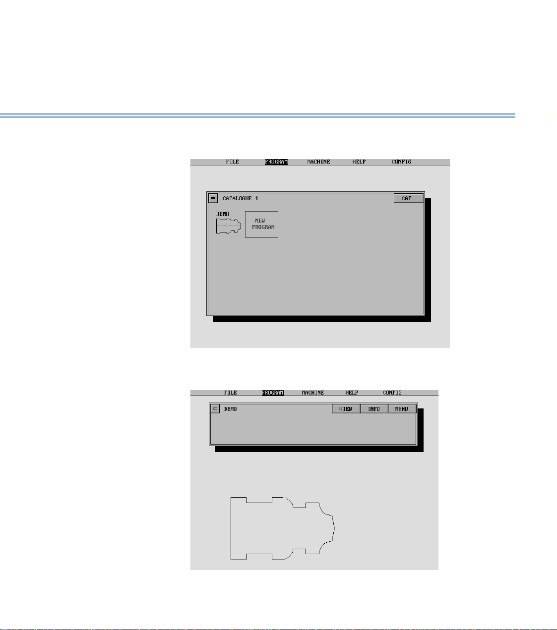
4. From the main menu select PROGRAM, then Program, and view Catalogue 1 to
identify the demonstration program which is called DEMO:
Select the Program
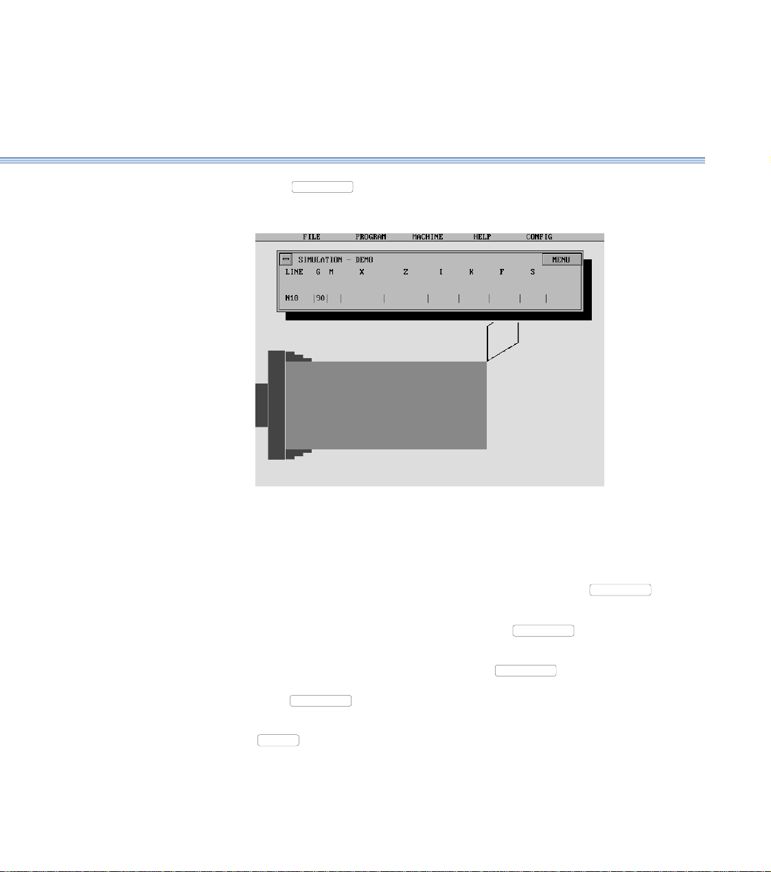
5. Select the program. The screen shows the Program display, with a 2D view of the
component:
2 Running the Demonstration ProgramBoxford 160 TCL
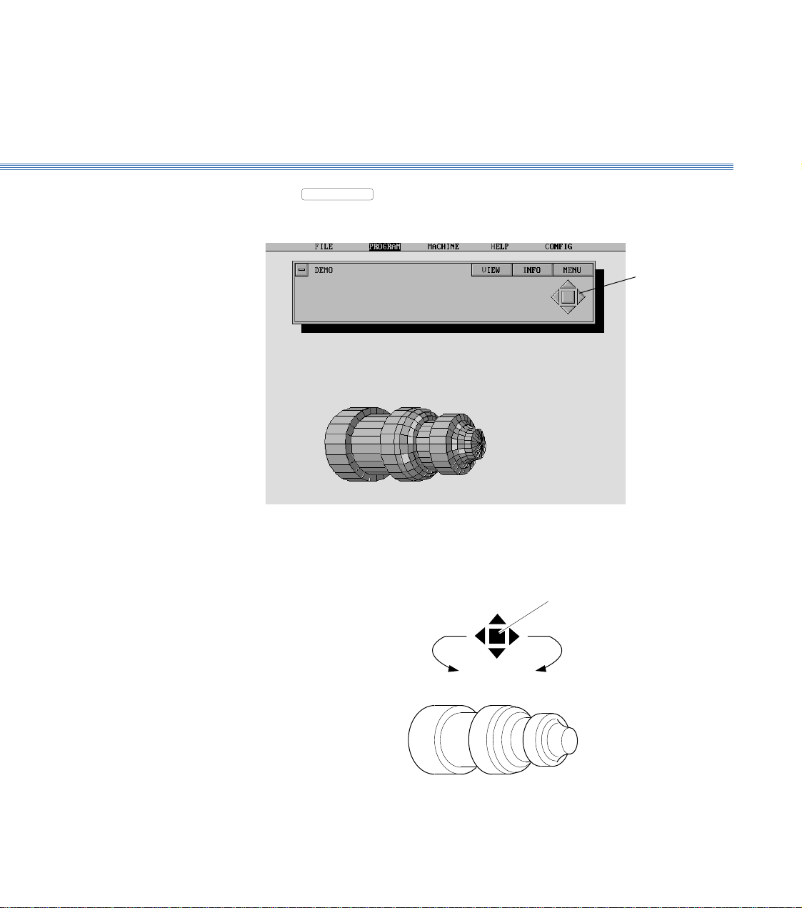
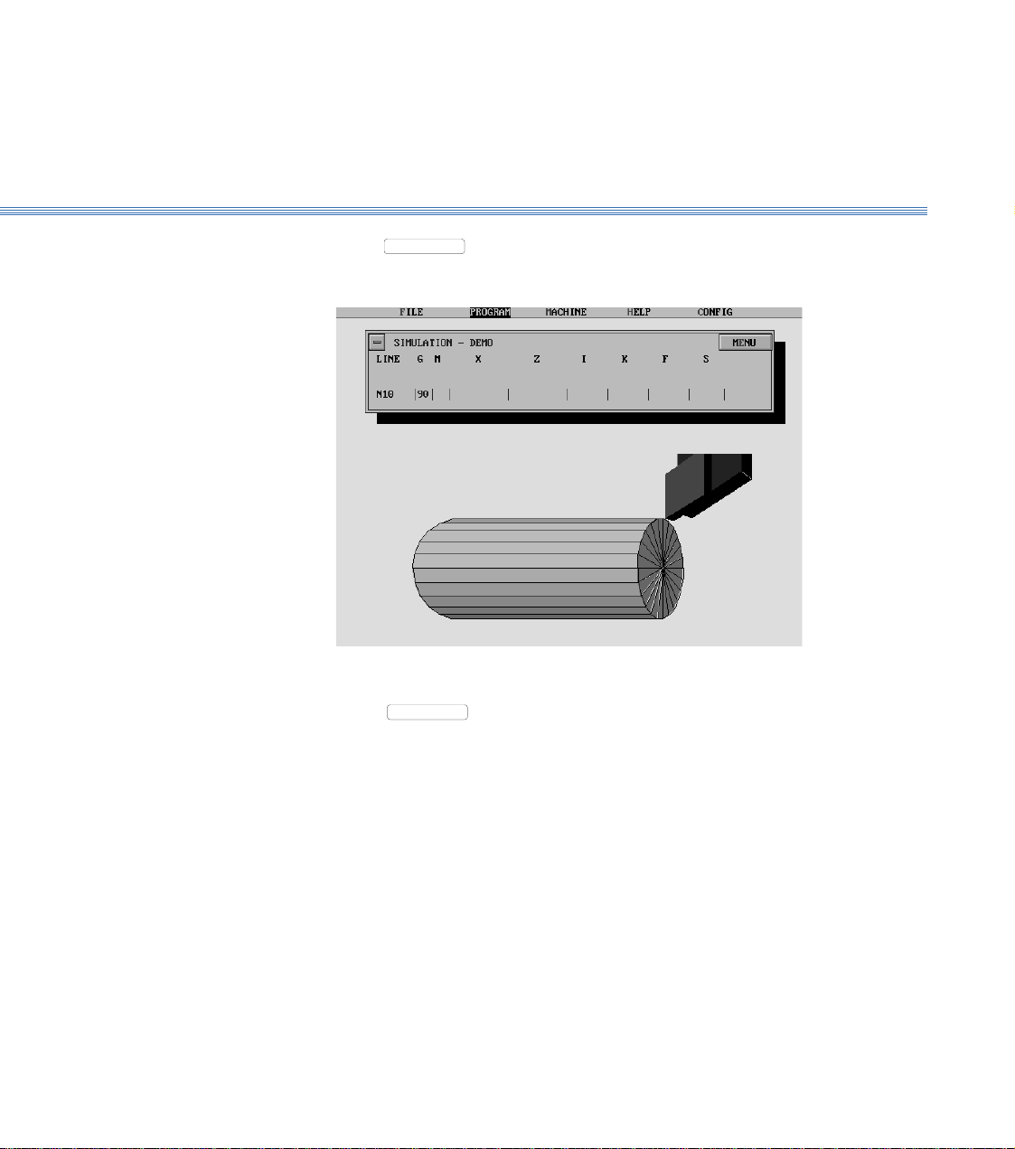
6. Select
VIEW
to produce a 3D view of the component. After a pause, the display
will show the 3D view:
Manipulate the 3D view as follows:
Using a Mouse
View the Component
Increase
size
Rotate
clockwise
Rotate
anticlockwise
Decrease
size
Restore to
original size
Control
buttons
2 Running the Demonstration ProgramBoxford 160 TCL
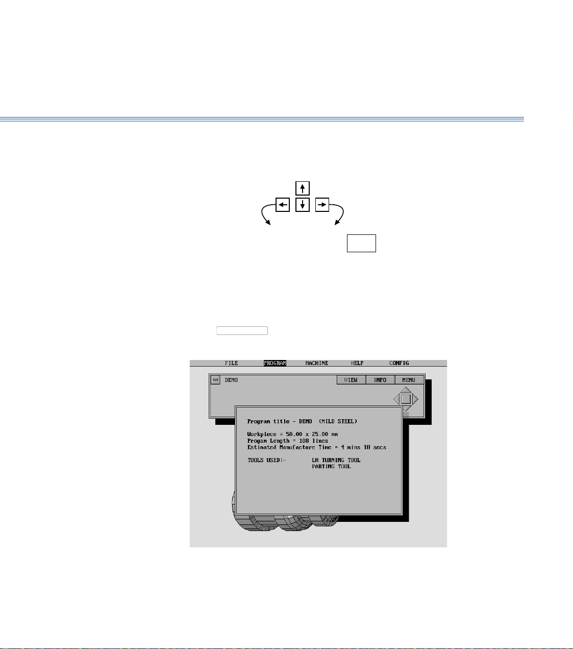
7. Select
INFO
to show the program details:
8. Turn off the program details display. (Click off the display window or press Return).
Note:
The time taken for the display to respond will depend on the speed of the PC and whether a co-processor
is fitted.
Using the Keyboard
Rotate
anticlockwise
Rotate
clockwise
Increase
size
Decrease
size
Restore
original view
HOME
Show the Program
Details
Boxford 160 TCL 2 Running the Demonstration Program
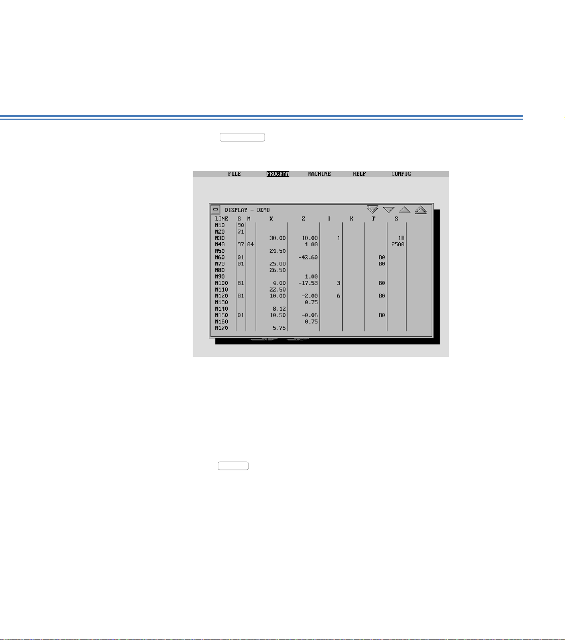
9. Select
MENU
, and then Display:
10. Turn off the program display.
Using a Mouse
Click on the 'off' button
Using the Keyboard
Press
ESC
.
Display the Program
2 Running the Demonstration ProgramBoxford 160 TCL
11. Select
MENU
, then 2D Simulate:
Repeatedly click the mouse button or press Return to move through the program line-
by-line. The simulation shows the tool movement and metal removed as each line of
the program is executed.
To move forward through the program to a specific line, select
MENU
, and then
Go to Line. Type the required line number when prompted, and press Return.
To produce a 3D view of the workpiece, select
MENU
and then 3D View. To
return to the 2D view, click the mouse button or press Return.
To run the simulation automatically, select
MENU
and then Fast Mode; the
program will be run in a continuous sequence. To return to line-by-line simulation,
select
MENU
and then Step Mode.
To end the simulation before the end of the program, click on the 'off' button or press
ESC
.
At the end of the program the screen returns to the program display.
Simulate Machining
- 2D
2 Running the Demonstration ProgramBoxford 160 TCL
12. Select
MENU
, then 3D Simulate:
Select
MENU
, and demonstrate the use of the options available as for 2D
simulation, until the screen again shows the program display.
13. Turn off the program display.
Refer to Section 9 - CNC and CAM Machining.
Simulate Machining
- 3D
Machine the
Component
Axes and Tooling
Boxford 160 TCL
3 Axes and Tooling
3.1. Axes and Datum
Axes: The toolholder can move in two axes, X and Z, (see Figure 3.1).
Datum Position: On new machines, all Datum positions and Tool Offsets are set at the factory when tooling and clamping
is ordered with the machine.
The offsets of all required tools are set in relation to the machine X and Z datum.
Before any Tool Offsets can be set, the Machine X and Z Datum has to be defined.
These value are provided with the machine documentation and are printed on a label
located inside the machine end guard.
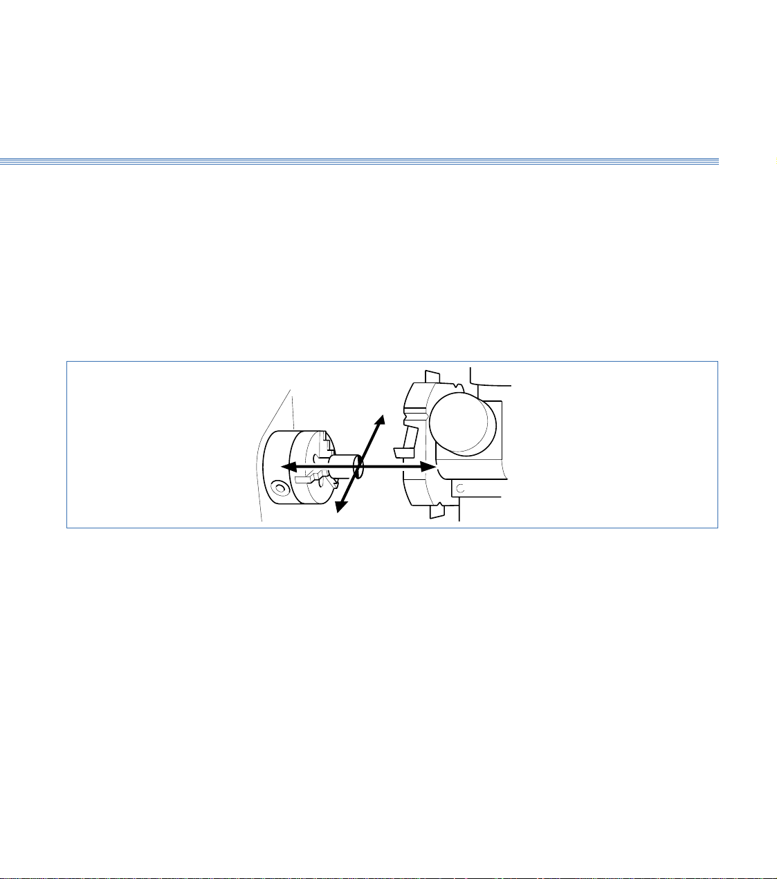
Figure 3.1 Axes and Datum Position
-Z +Z
+X
-X
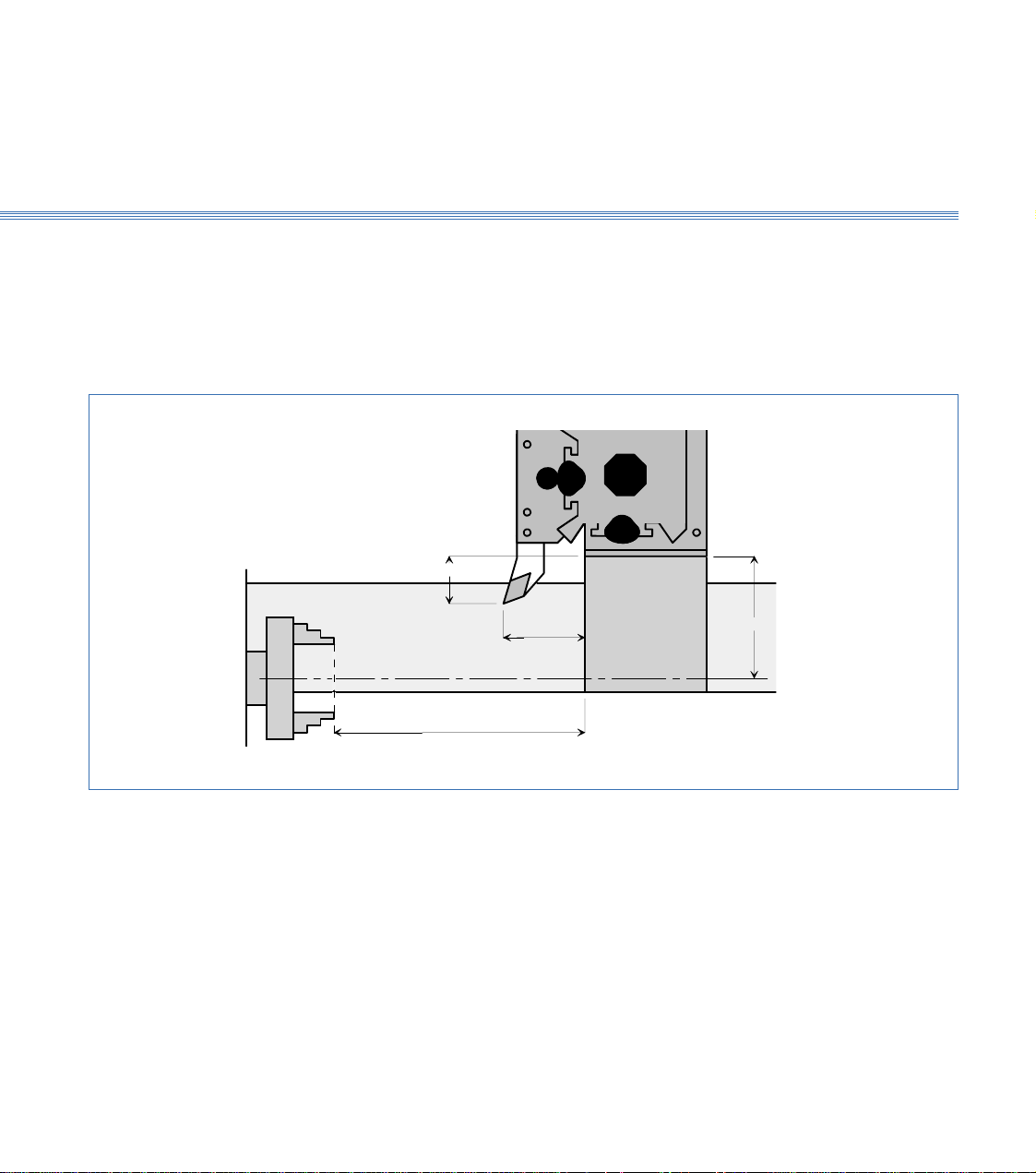
Machines with Turrets: From the machines Home Position, the Machine Z Datum is the measured distance from
the front face of the chuck jaws to the turret disc front face as shown in the diagram 3.2.
The Y Datum is the measured distance from the spindle centreline to the centreline of the internal
tool bores on the turret.
Boxford 160 TCL Axes and Tooling
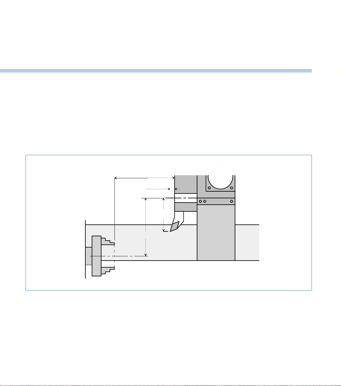
Tool Offsets: The Tool Z offset is the distance from the Turret Disc front face to the Tool Cutting
tip point.
The X offset is the distance from the centreline of the internal tool bores on the turret
to the Tool Cutting Tip Point (therefore theoretically all drills should have an X offset
of Zero).
The X offset is always twice the measured distance because the Boxford software uses
X values specified in Diameter (not radius).
3.1
Figure 3.2 Turret
Tool X Offset
Datum X Value
TURRET
Datum Z Value
Tool Z Offset
Centre Line
of Internal
Tool Holder
Centre Line of Spindle
Axes and Tooling
Boxford 160 TCL
Machines with Quick Change Tool Posts:
From the machines Home Position, the Machine Z Datum is the measured distance from
the front face of the chuck jaws to the front face of the machine cross slide as shown in the diagram
below. (figure 3.3)
The Y Datum is the measured distance from the spindle centreline to the bottom face of the tool
post mounting plate.
3.1
Figure 3.3 Quick Change
Tool Z Offset
Tool X Offset
Datum X Value
Datum Z Value
Centre Line of Spindle
Tool Offsets: The Tool Z offset is the distance from the Cross Slide front face to the Tool Cutting
tip point.
The X offset is the distance from the bottom face of the tool post mounting plate to
the Tool Cutting Tip Point.
The X offset is always twice the measured distance because the Boxford software uses
X values specified in Diameter (not radius).
Boxford 160 TCL Axes and Tooling
Figure 3.4 Turret Tool Positions
3
2
4
5
6
7
8
1
External tools: 1, 3, 5, 7
Internal tools: 2, 4, 6, 8
Machines without homing switches:
1: Reference tool
7: Second tool
3.1

Axes and Tooling
Boxford 160 TCL
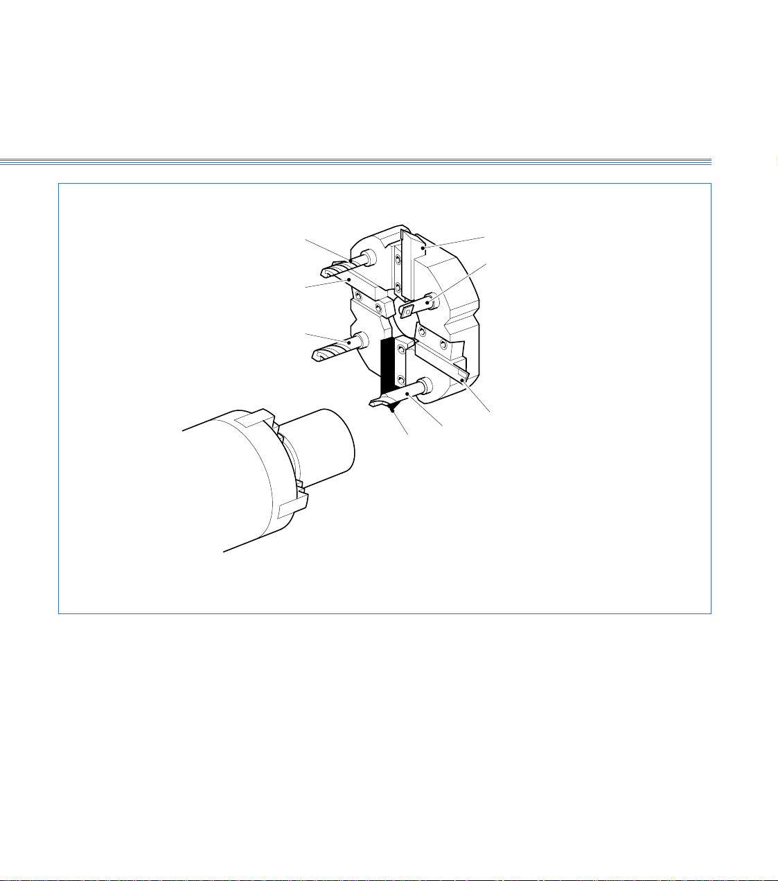
3.2 Turret (Figure 3.4)
The turret is a motor driven, disc type toolpost with positions for up to eight tools, four
external and four internal; each position is numbered.
Tools can be accessed by indexing the turret using the TURRET INDEX push button
on the machine controls or from the software.
External tools are secured in radial slots by tapered clamp blocks held by two fixing
screws. Longitudinal positioning is achieved by pushing the tool towards the turret
centre so that it touches the location stop. Internal tools are secured in their predrilled
holes with tubular toolholders and two sunken screws.
This will normally have been set at the factory and should require no adjustment. If
it is found to be incorrect it is recommended that a Boxford service engineer is called.
However it is permissible to adjust it by putting a tool into the working position, then
inserting packing as appropriate between the turret toolpost and cross-slide. If this does
not achieve correct tool height, or other tools heights are still incorrect, contact the
factory.
Fitting Tools
Setting Tool Height
3.2
Boxford 160 TCL Axes and Tooling
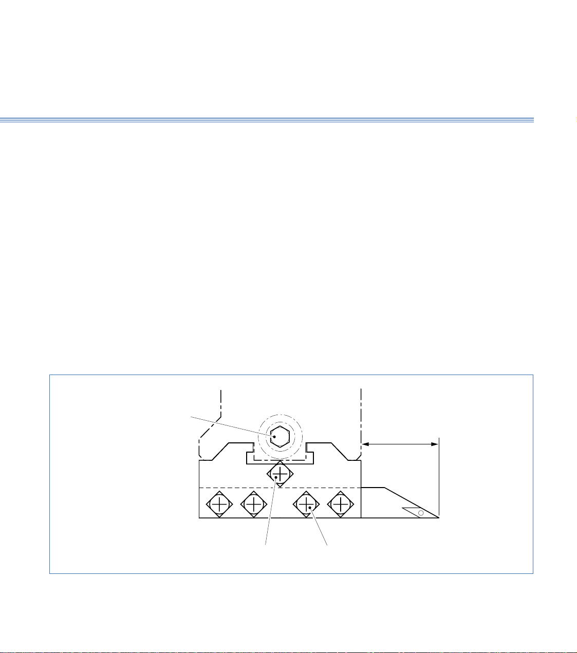
3.3 Quick Change Toolpost
The quick change toolpost has two slots to provide for convenient and rapid manual
tool changing. A toolholder with a tool already secured in it by the four securing screws
is placed into the shaped slots which provide instant positive location, and is rigidly held
there by tightening the single clamping screw, using the clamp screw key provided. The
toolpost will only accept a single toolholder at a time. External tools are fitted to the
X axis slot while internal tools use the Z axis slot.
A quick change toolpost can be fitted to the lower section of the X-axis cross slide in
addition to a gang plate.
Fit the LH turning tool into the standard flat bottomed toolholder by tightening the
four securing screws onto the tool shank. The tool should protrude approximately
20mm (0.75in) from the toolholder face. Keep this dimension consistent for all the
external tools. Put the toolholder into the toolpost and lock it into position using the
clamping screw.
Figure 3.5 Quick Change Toolpost
Fitting Tools
(Figures 3.5 and 3.6)
Tool Tool Securing Screws
Tool Clamping Screw
3.3
Axes and Tooling
Boxford 160 TCL
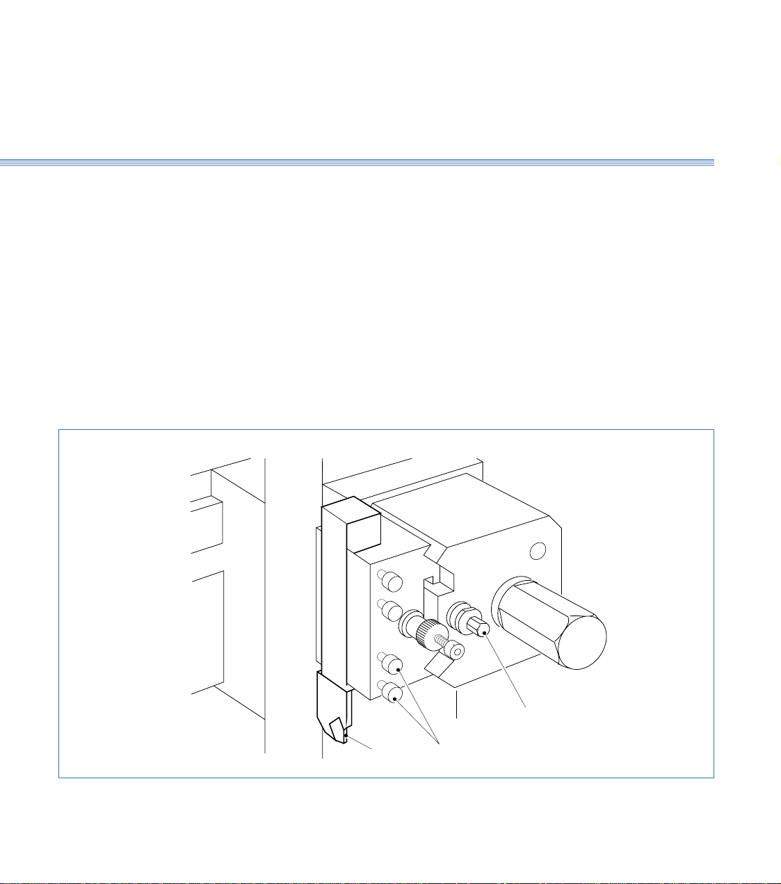
Refer to Section 10 Manual Machining to move the tool manually to set the tool height,
which is checked by taking a light facing cut on the end of the workpiece. If adjustment
is needed to centre the tool, use the centre height adjustment screw on toolholder as
follows:
1. Visually check the height to the workpiece centre point. The actual height from the top
of the cross slide to the centre of the spindle is stamped on the left face of the bed
adjacent to the headstock cover.
Note:
Do not confuse this value with the machine serial no. which is also stamped here.
2. To adjust the height slacken the toolpost clamp screw and the centre height adjustment
screw. Turn the knurled adjustment knob clockwise to raise the tool, anticlockwise to
lower it.
When the height is correct tighten the Allen screw then tighten the toolholder clamp
screw.
3. Check that the tool is exactly on the centre line by taking a light facing cut on the end
of the workpiece, using spindle in reverse direction. Repeat adjustment above as
necessary.
Height Setting-External Tools
Figure 3.6 Tool Fitting and Adjustment
Tool
Clamping
Screw
Constant
Centre Height
Adjustment Screw
Tool Securing
Screws
3.1
Boxford 160 TCL Axes and Tooling
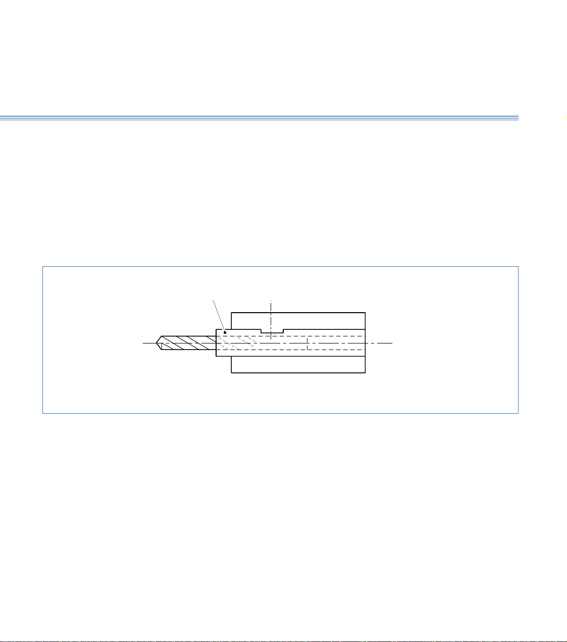
These tools can be fitted directly into the V location toolholders intended for use with
the drills. Although not essential, it is better if they are located into a tubular holder.
This can easily be made as shown in Figure 3.7.
Put a toolholder with its tool on to the toolpost and set the centre height to the
workpiece centre line exactly as for external tools. Repeat this procedure for all of the
tools.
Height Setting - Internal Tools
Drill Tube
Figure 3.7 Internal Tool Fitting Detail
3.3
Axes and Tooling
Boxford 160 TCL
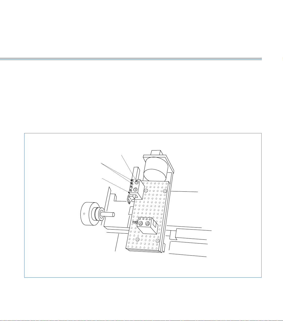
3.4 Gang Plate (Figure 3.8)
This is a plate with drilled holes enabling up to three simple channel shaped toolholders
to be clamped on to it. Tool positions are free, limited by hole line-up between
toolholder and gang plate and by ensuring that every tool mounted can reach the work
over the required range without fouling anything or causing other tools to foul
something.
Select a tool position and fit the channel toolholder using the securing screws. Clamp
the tool into it with the four clamping screws.
There is no tool height setting adjustment provided as this is pre-set at the factory. If
correction is needed, contact the factory.
Fitting the Tools
Figure 3.8 Gang Plate
Setting Tool Height
Clamping
Screws
Channel
Toolholder
Securing
Screws
3.4

Boxford 160 TCL Axes and Tooling
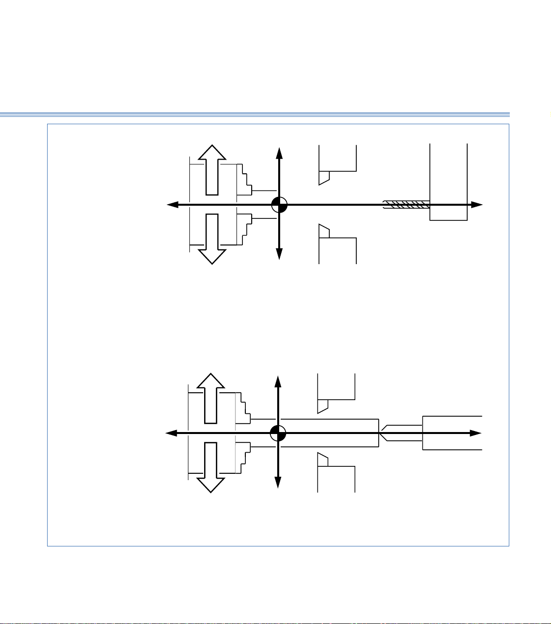
The spindle can run forward (anticlockwise when viewed on chuck jaws) and in reverse
(clockwise when viewed on chuck jaws). Direction and speed of rotation are controlled
either by the SPIND FWD/SPIND REV buttons on the machine control panel (refer
to Installation and User Manual Section 6 Machine Controls) or by means of M codes
(M03 = Forward and M04 = Reverse) selected from software.
For machining a workpiece held in the chuck with the tool fitted in the normal way,
i.e. with the cutting edge uppermost, the direction of rotation is as follows:
Direction M Code
External turning, toolholder at back Reverse M04
External turning, toolholder at front Forward M03
Internal turning Forward M03
If tools are fitted upside down, take care to select the appropriate direction of spindle
rotation.
Once the initial tool is specified, which then sets the direction of rotation, ensure that
all subsequent tools are fitted in the same orientation to avoid the need to reverse the
direction of rotation at tool changes while running a program.
3.5 Spindle Rotation and Tool Orientation
Rotation
(Figure 3.9)
Tool Orientation
3.5
Axes and Tooling
Boxford 160 TCL
+Z
EXTERNAL TURNING
Tool holder at back
Tool holder at front
FORWARD
REVERSE
INTERNAL TURNING
-Z
+X
-X
WORKPIECE IN CHUCK
Figure 3.9 Spindle Rotation and Tool Orientation
NEGATIVE X VALUES ONLY
+Z
FORWARD
REVERSE
-Z
+X
-X
USING TAILSTOCK POSITIVE X VALUES ONLY
3.5
Boxford 160 TCL Axes and Tooling
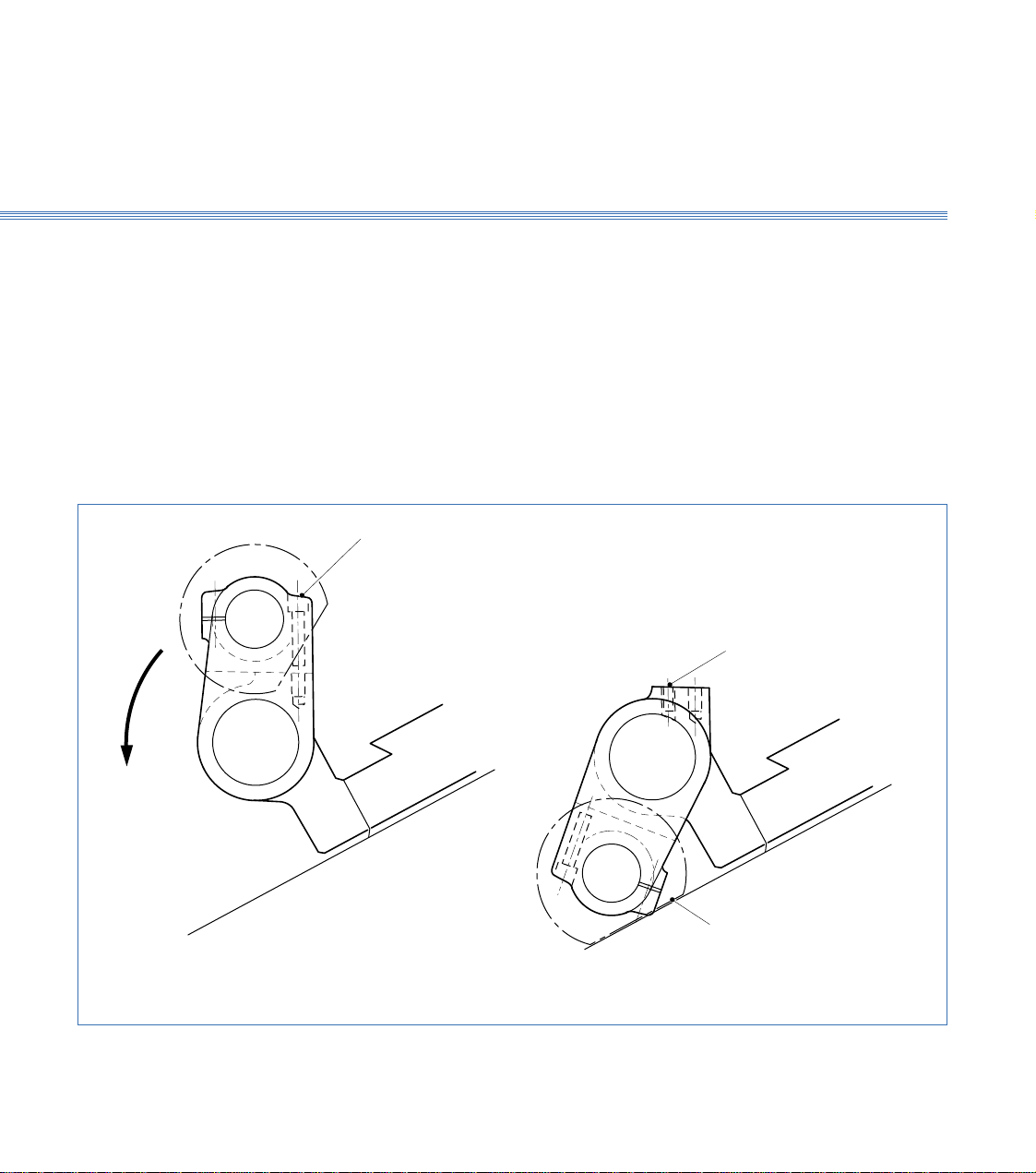
3.6 Tailstock (Figure 3.10)
The tailstock is bolted to the main slide. The upper part can be rotated about a
longitudinal axis to its working or parked positions. When not required, the upper part
is swung down and locked into its parked position to allow the toolholder its full travel
along the Z axis. The tailstock contains a quill to hold a centre, and is adjusted manually
in the Z axis.
Two fixing screws secure the two halves of the tailstock rigidly into the working
position.
Removing these screws allows the top half of the tailstock to be swung down to rest
against the machine frame. This exposes a sunken Allen screw for securing the parked
tailstock section in place.
Position Changing
and Securing
Fixing Screws
Locking Screw
Flat on
Handwheel
Figure 3.10 Tailstock
3.6

Axes and Tooling
Boxford 160 TCL
3.7 Chuck
A manual or pneumatic chuck may be fitted. Pneumatic chucks are operated either by
using the CHUCK OPEN/CHUCK CLOSE pushbuttons on the machine control
panel (refer to Installation and User Manual Section 6 Machine Controls) or from
within software by use of appropriate M code (M40 = Open, M39 = Close).
Unless specified otherwise, pneumatic chuck jaws are prebored at the factory to 20mm
diameter. Should work with larger diameter workpieces be undertaken, the pneumatic
chuck jaws can be bored out to avoid the need to purchase another pneumatic chuck,
as follows:
1. Press the CHUCK CLOSE button and set the jaws to position to provide
sufficient material for boring. To move the jaws unfasten the two screws in the jaws,
raise the jaws from the serration plates and position them accordingly, then refasten
the screws ensuring that the jaws are equi-distant from the centre line of the chuck.
2. Make a washer 1mm thick with bore the same diameter that the chuck is to be bored.
The outside diameter of washer can be 30mm.
3. Press the CHUCK OPEN button.
4. Bore out the face of the jaws 1mm deep, 30.12mm diameter (0.12mm bigger than the
outside diameter of the washer).
5. Place the washer on to the machined jaw face and press the CHUCK CLOSE button
to clamp the outside diameter of the washer.
6. Revolve the chuck forward at approximately 2000 rev/min.
7. Bore out the jaws using the washer bore as a gauge. Use the axis control buttons to
provide tool movement with the FEED knob set to 75%.
8. When boring is complete stop the spindle and press the CHUCK OPEN button to
release the washer.
3.7
Axes and Tooling
Boxford 160 TCL
3.8 Tool Libraries
The 160 software provides a Tool Data Library which enables details of tooling and
offsets to be entered and a Tool Library from which tools can be selected for inclusion
in the Tool Data Library. The library is set up by means of a tooling menu.
Before attempting to set up the tooling for the first time, view the libraries and the
tooling menu to become familiar with the details, as follows:
1. Switch on the PC, run the 160 software.
2. From the Simulation and Manufacture software main menu, select MACHINE and
then Tools.
The screen shows the Tool Data Library, (Figure 3.11). Practice selecting tools using
the mouse and keyboard.
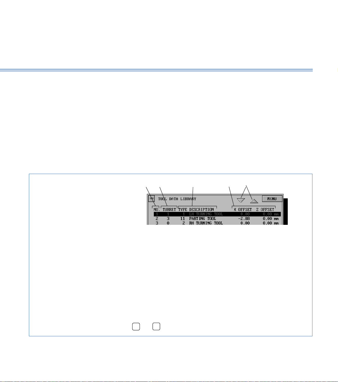
Figure 3.11 Tool Data Library
1 2 3 4 5
Tool Data Library
To select a tool:
Using a mouse
Click on the scroll buttons (5) to highlight the required tool,
point to required tool and click mouse button.
Using the keyboard
Press
➔
or
➔
to highlight the required tool.
1. Tool number used by CNC program to select required tool
2. Tool position on Turret (not used with Gang plate or Quick change tool
holder)
3. Tool type and description (selected from tool catalogue)
4. Tool offsets
5. Scroll buttons
3.8
Boxford 160 TCL Axes and Tooling
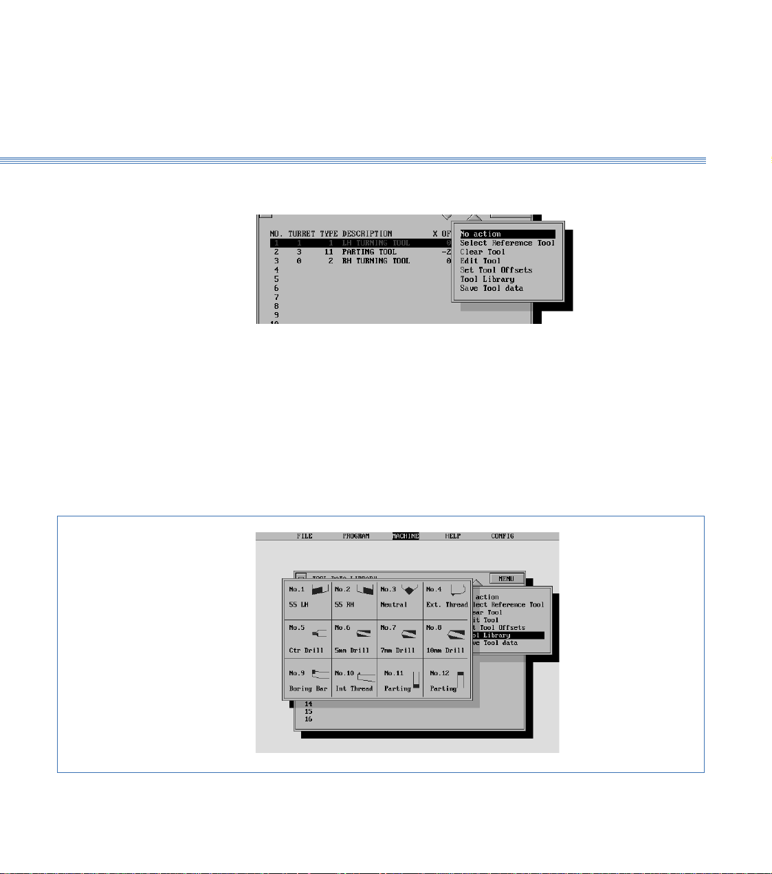
3. Select MENU to display the tooling menu:
The use of these options for setting and editing the Tool Data Library is detailed later
in this section.
Note:
After setting up or editing the library, always select Save Tool data.
4. From the tooling menu, select Tool Library.
The screen shows the Tool Library, (Figure 3.12).
Turn off the Tool Library display to reveal the Tool Data Library.
Figure 3.12 Tool Library
Tooling Menu
Tool Library
3.8

3.9Axes and ToolingBoxford 160 TCL
Note:
A billet of the appropriate size will be required for this procedure. In order to run the demonstration
program, a LH turning tool and a parting tool are required. To run the program, set up the LH
turning tool as the first tool and the parting tool as the second tool in the following procedure.
1. Fit the required tools into the toolholding system supplied.
With the quick change toolpost, fit the first tool required. After setting the offset of
the first tool, it will be necessary to substitute the next tool before setting its offset.
If the toolholder is too close to the chuck to allow the tools to be fitted, move the
toolholder away from the chuck under manual control, (see Section 10 - Manual
Machining).
2. Check that the POWER RESET button on the machine control panel has been pressed
to initialise the machine.
3. Run the Simulation and Manufacture software. From the main menu select CONFIG
and then Program.
4. On the PROGRAM display, set UNITS MODE to the units required for tool offsets
and programming.
5. If a turret is fitted, select CONFIG and then Hardware, and check that TURRET is
set to FITTED.
Note: It is only necessary to set the datum position when the machine is first installed, or if the original
setting is lost. In order to set the datum position, the information supplied with the machine will be
required; this information consists of an X and a Z axis measurement.
6. From the main menu, select MACHINE and then Datum Position. The screen
shows:
3.9 Setting Up
Fit Tooling
Configure Software
Set Datum Position

Boxford 160 TCL 3.9 Axes and Tooling
Enter the X and Z axis measurements supplied with the machine, and select
SAVE
.
The screen returns to the main menu.
7. From the main menu, select MACHINE and then Tools to display the Tool Data
Library. Defaults of the first tool will be highlighted, for example:
Check the settings. If they are correct, continue at step 15 to set the second tool.
For the demonstration program, the settings should be as shown.
8. Select the tool to be edited by clicking on it with the mouse, or on the keyboard use
the
➔
➔
keys to highlight the required tool and press Return.
9. The screen shows the tool editing display, with the first item (Tool type) highlighted,
(refer to Figure 3.13).
Edit the display to show the required Tool type (and Turret position if applicable). Do
not edit the offsets.
10. Select
MENU
, and then Set Tool Offsets.
11. The screen shows:
3.9Axes and ToolingBoxford 160 TCL
Follow the instructions, selecting AUTO mode on the machine control panel and
pressing both X axis buttons simultaneously, then both Z axis buttons, to home the
axes.
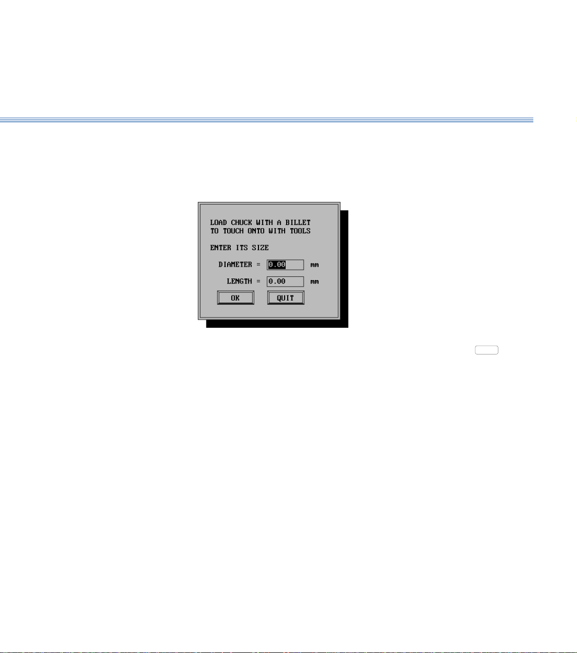
12. When the axes are homed, the screen shows:
Fit a billet into the chuck. Enter its diameter and length, and select
OK
or press
Return.
13. The screen shows the tool offsets setting display, (Figure 3.14).
On the machine control panel, select MANUAL mode. Using the X and Z axis buttons,
follow the instructions appropriate to a drill or other type of tool to position the point
of the tool on the reference diameter (the periphery of the billet).
Loading...