

Page 1

Programming Manual
Boxford 160 TCL
CNC Turning
Machine Tool
Boxford
Boxford Ltd.,
Wheatley, Halifax, West Yorkshire,
England, HX3 5AF.
(Registered Office)
Telephone: 01422 358311
Fax: 01422 355924
E-Mail: info@boxford.co.uk
Web: www.boxford.co.uk
Page 2

Boxford 160 TCL Contents
Contents
1 Introduction
2 Running the Demonstration Program
3 Axes and Tooling
3.1 Axes and Datums
3.2 Turret
3.3 Quick Change Toolpost
3.4 Gang Plate
3.5 Spindle Rotation and Tool Orientation
3.6 Tailstock
3.7 Chuck
3.8 Tool Libraries
3.9 Setting Up
4 Main Front End Menu
5 CAD and CAM Processing
5.1 Functions
5.2 Information Required
5.3 Creating a CAD Profile
5.4 CAD Window
5.5 Drawing Aids
5.6 Drawing Tools
5.7 Editing Tools
5.8 3D Renderer
5.9 Example
5.10 CAM Processing a Profile
5.11 CAM Processor Error Messages
6 DXF File Imports
Page 3

7 Administration Mode
7.1 Access & Password Setting
7.2 Tool Library
7.3 Material Cutting Data
7.4 Internal Machining Data
7.5 Park Position and Units
7.6 Language Settings
8 Manual Data Input CNC Programming
8.1 Operations and Programming Sheets
8.2 Absolute and Incremental Co-ordinates
8.3 Speeds and Feeds
8.4 Program Format
8.5 Preparatory Functions (G Codes)
8.6 Miscellaneous Functions (M Codes)
8.7 Canned Cycles
8.8 Inputting a New Program
8.8.1 Information required
8.8.2 Tabulated Format
8.8.3 Compact Format
8.9 Saving a Program
8.10 Examining an Existing Program
8.11 Editing a Program
8.11.1 New Programs
8.11.2 Existing Programs
8.11.3 MENU Editing Options
8.12 Continuing a Program
ContentsBoxford 160 TCL
9 CNC and CAM Machining
9.1 Initial Checks
9.2 Manufacture
9.3 Options During Machining
10 Manual Machining
11 Robotic Interfacing
Page 4

CNC Tutorials and Exercises
Tutorial 1: X and Y Co-ordinate Calculation -
Absolute and Incremental Co-ordinates
Exercise 1: Calculation of Co-ordinates
Tutorial 2: Linear Interpolation
Exercise 2: Linear Interpolation - Absolute Co-ordinates
Tutorial 3: Canned Cycles - Hole Drilling and Pocket Milling
Exercise 3: Canned Cycles - Programming a Tool Change
Tutorial 4: Circular Interpolation - Clockwise and Counter-clockwise
Exercise 4: Circular Interpolation
Tutorial 5: Combining Operations and Tool Changing
Exercise 5: Combining Operations
ContentsBoxford 160 TCL
Tutorial 6: Subroutines
Exercise 6: Subroutines
Tutorial 7: Mirror Images
Exercise 7: Mirror Images
Tutorial 8: Further Canned Cycles - Pitch Circle Drilling and Dish Milling
Exercise 8: Use of Canned Cycles - Pitch Circle Drilling and Dish Milling
Tutorial 9: Subroutines, Mirror Images and Circular Interpolation
Exercise 9: Subroutines and Mirror Images
Tutorial 10: Datum Shift and Jump to Line
Exercise 10: Datum Shift and Jump to Line
Operations Sheet
Programming Sheet
Page 5

1 Introduction
This manual gives guidance in using the 160TCL CAD/CAM software to create ISO
G&M code programs for turned components, and in component manufacture.
The 160TCL CAD/CAM software includes a demonstration program (called
DEMO), and a number of tutorial programs.
It is suggested the manual is used as follows:
1. Refer to section 2 and run the demonstration. This will provide rapid familiarisation
with the operation of the software and the machining process.
2. Study Section 3 to become proficient in setting up the tooling.
3. Refer to sections 4 and 5 to demonstrate the ease of operation of the integrated CAD
and CAM processor package.
4. Refer to Section 6 to become familiar with the conventions for importing DXF files
from third party CAD packages.
5. Refer to Section 7 for details of the functions available to administrators (tutors) of the
CAD/CAM system.
6. Use section 8 for detailed instruction in CNC programming.
Tutorial 1 is used as an example to demonstrate the stages of programming and
software operation.
7. Use the Tutorials and Exercises in the order in which they appear, to progress from
basic programming skills to proficiency in the more advanced features of CNC
programming.
8. When programs have been written and verified, refer to section 10 as required, to
machine components.
Page 6

2 Running the Demonstration ProgramBoxford 160 TCL
2 Running the Demonstration
Program
The demonstration program contains examples of parallel and radius turning, and a
finished component can be machined from the billet supplied with the machine. Run
the program as follows to provide a tutorial in programming and machining:
Set Up the Machine
Gang Plate: Set both tools into individual toolholders, then fix toolholders into suitable locations
Quick Change: Set both tools into individual toolholders. Fit the LH turning tool and toolholder
Check Tool Settings
1. Make sure the billet is securely fitted in the chuck. Check that the first tool to be used
is the LH turning tool (this is the reference tool). and the second tool is the parting tool.
Set these up as follows:
Turret: Fit LH turning tool in position 1, Parting tool in position 7. (Refer to Figure 3.2 in
Section 3 for tool positions in the turret).
on the gang plate to permit their use in sequence.
assembly into the X-axis slot of the toolpost (refer to Figure 3.4 in Section 3 for tool
fitting and axis slot). During machining, the machine will stop and it will be necessary
to remove and replace the reference tool with the parting tool assembly in the same
X-axis toolholder slot.
2. Run the Simulation and Manufacture software and check that it is correctly configured
by selecting CONFIG from the main menu. (Refer to Installation and User Manual
Section 5 - Configuring the 160 Software, if necessary).
3. From the main menu, select MACHINE and then Tools to display the Tool Data
Library. Check the settings of the LH turning tool and the parting tool, which should
be as follows:
NO. TURRET TYPE DESCRIPTION X OFF Z OFF
1 1 1 LH TURNING TOOL ( - as set - )
2 7 11 PARTING TOOL ( - as set - )
If the settings are incorrect, refer to Section 3 - Axes and Tooling, 3.9 Setting Up:
Select and Set LH Turning Tool, and
Select and Set Parting Tool.
Page 7
2 Running the Demonstration ProgramBoxford 160 TCL
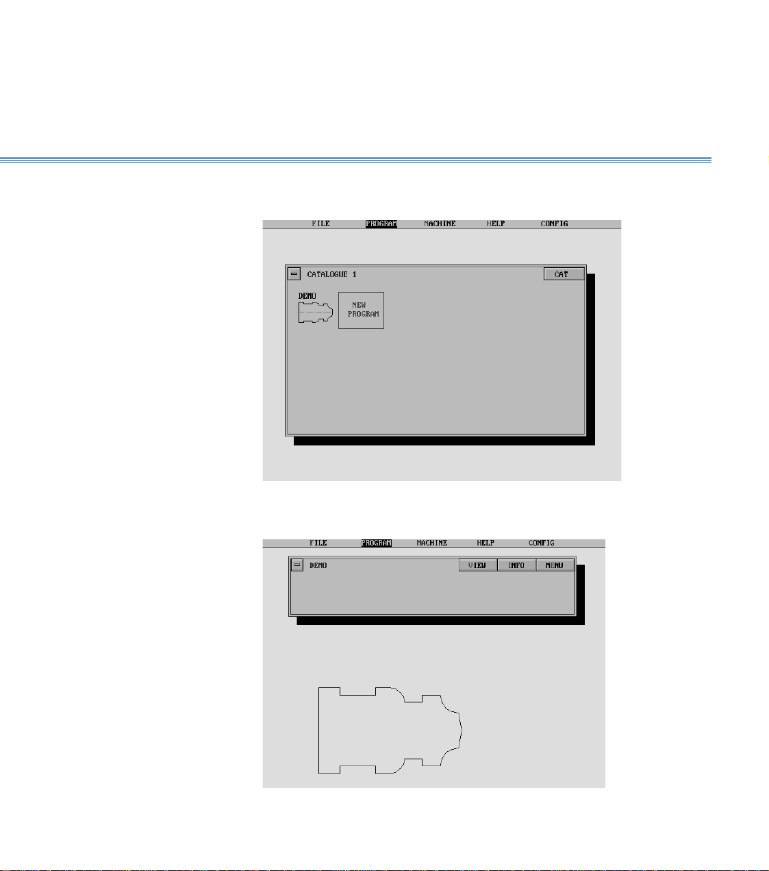
Select the Program
4. From the main menu select PROGRAM, then Program, and view Catalogue 1 to
identify the demonstration program which is called DEMO:
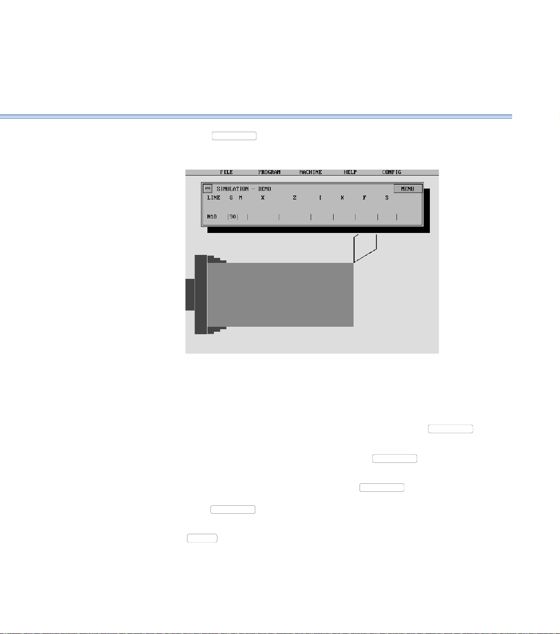
5. Select the program. The screen shows the Program display, with a 2D view of the
component:
Page 8
2 Running the Demonstration ProgramBoxford 160 TCL
Increase
size
Rotate
clockwise
Rotate
anticlockwise
Decrease
size
Restore to
original size
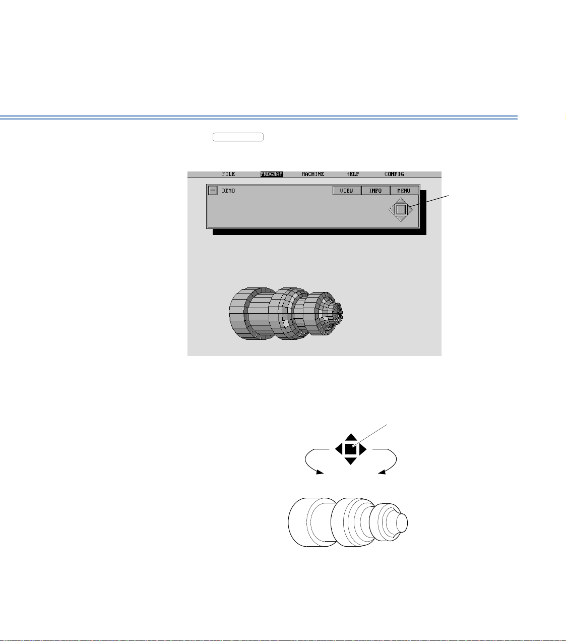
View the Component
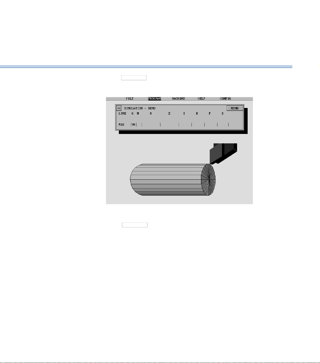
6. Select
VIEW
to produce a 3D view of the component. After a pause, the display
will show the 3D view:
Manipulate the 3D view as follows:
Using a Mouse
Control
buttons
Page 9
2 Running the Demonstration ProgramBoxford 160 TCL
Using the Keyboard
Increase
size
Rotate
anticlockwise
Decrease
size
Note:
The time taken for the display to respond will depend on the speed of the PC and whether a co-processor
is fitted.
Rotate
clockwise
HOME
Restore
original view
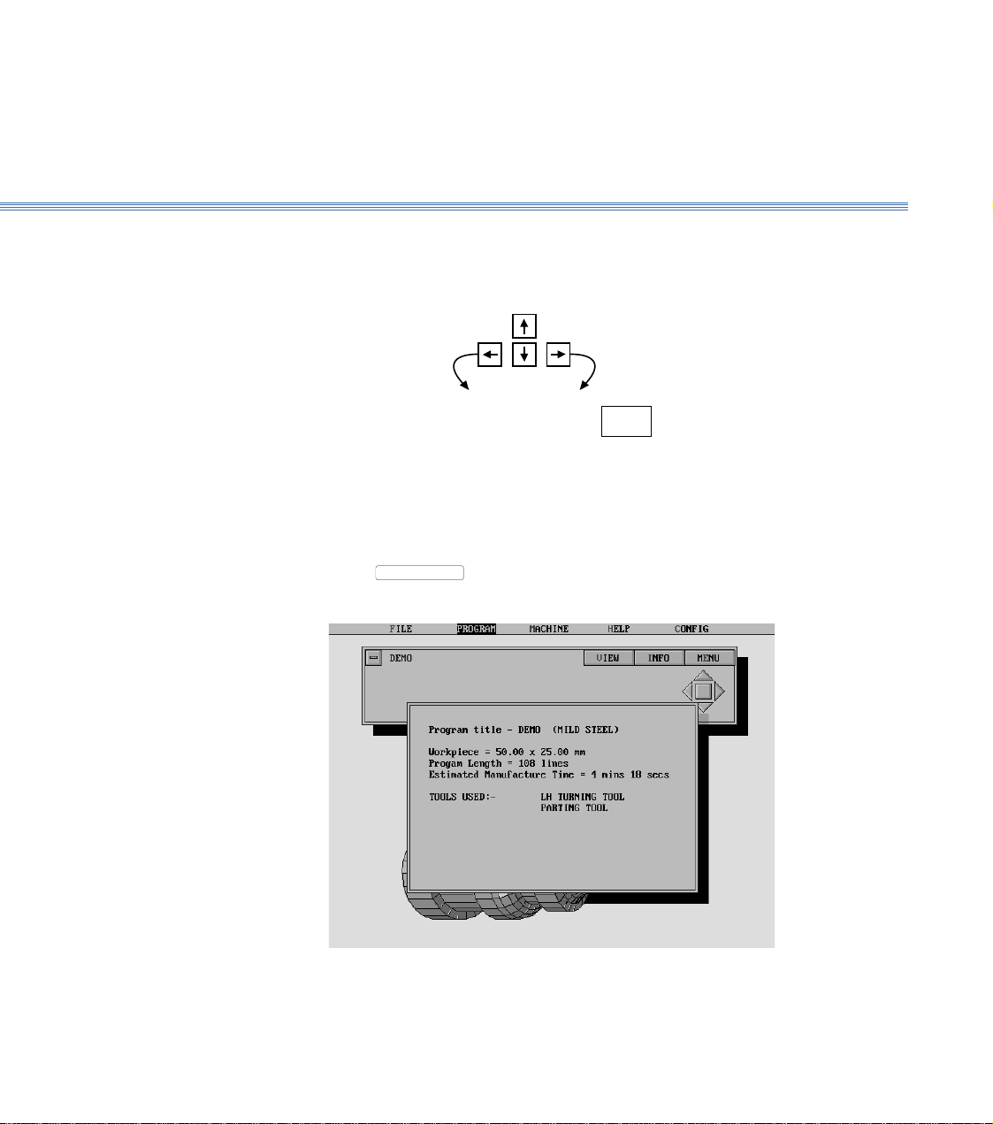
Show the Program
Details
7. Select
INFO
to show the program details:
8. Turn off the program details display. (Click off the display window or press Return).
Page 10
Boxford 160 TCL 2 Running the Demonstration Program
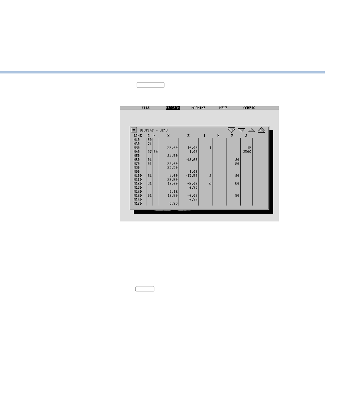
Display the Program
9. Select
MENU
, and then Display:
10. Turn off the program display.
Using a Mouse
Click on the 'off' button
Using the Keyboard
Press
ESC
.
Page 11
2 Running the Demonstration ProgramBoxford 160 TCL
Simulate Machining
- 2D
11. Select
MENU
, then 2D Simulate:
Repeatedly click the mouse button or press Return to move through the program line-
by-line. The simulation shows the tool movement and metal removed as each line of
the program is executed.
To move forward through the program to a specific line, select
MENU
, and then
Go to Line. Type the required line number when prompted, and press Return.
To produce a 3D view of the workpiece, select
MENU
and then 3D View. To
return to the 2D view, click the mouse button or press Return.
To run the simulation automatically, select
MENU
and then Fast Mode; the
program will be run in a continuous sequence. To return to line-by-line simulation,
select
MENU
and then Step Mode.
To end the simulation before the end of the program, click on the 'off' button or press
ESC
.
At the end of the program the screen returns to the program display.
Page 12
2 Running the Demonstration ProgramBoxford 160 TCL
Simulate Machining
- 3D
12. Select
Select
simulation, until the screen again shows the program display.
13. Turn off the program display.
MENU
MENU
, then 3D Simulate:
, and demonstrate the use of the options available as for 2D
Machine the
Component
Refer to Section 9 - CNC and CAM Machining.
Page 13
Boxford 160 TCL
Datum Position: On new machines, all Datum positions and Tool Offsets are set at the factory when tooling and clamping
Axes and Tooling
3 Axes and Tooling
3.1. Axes and Datum
Axes: The toolholder can move in two axes, X and Z, (see Figure 3.1).
is ordered with the machine.
The offsets of all required tools are set in relation to the machine X and Z datum.
Before any Tool Offsets can be set, the Machine X and Z Datum has to be defined.
These value are provided with the machine documentation and are printed on a label
located inside the machine end guard.
+X
-Z +Z
-X
Figure 3.1 Axes and Datum Position
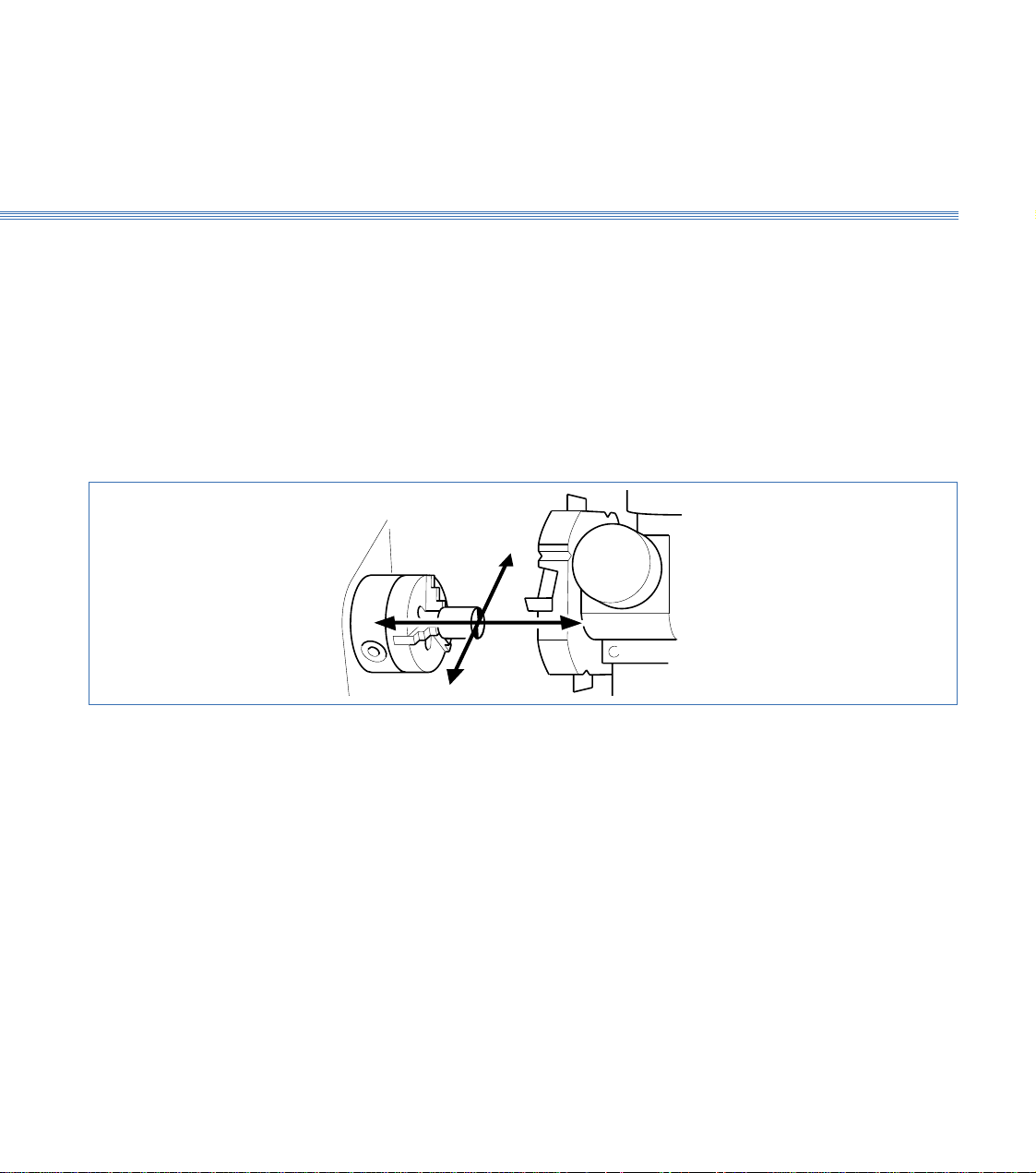
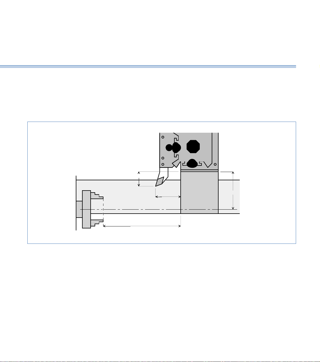
Machines with Turrets: From the machines Home Position, the Machine Z Datum is the measured distance from
the front face of the chuck jaws to the turret disc front face as shown in the diagram 3.2.
The Y Datum is the measured distance from the spindle centreline to the centreline of the internal
tool bores on the turret.
Page 14
Boxford 160 TCL Axes and Tooling
3.1
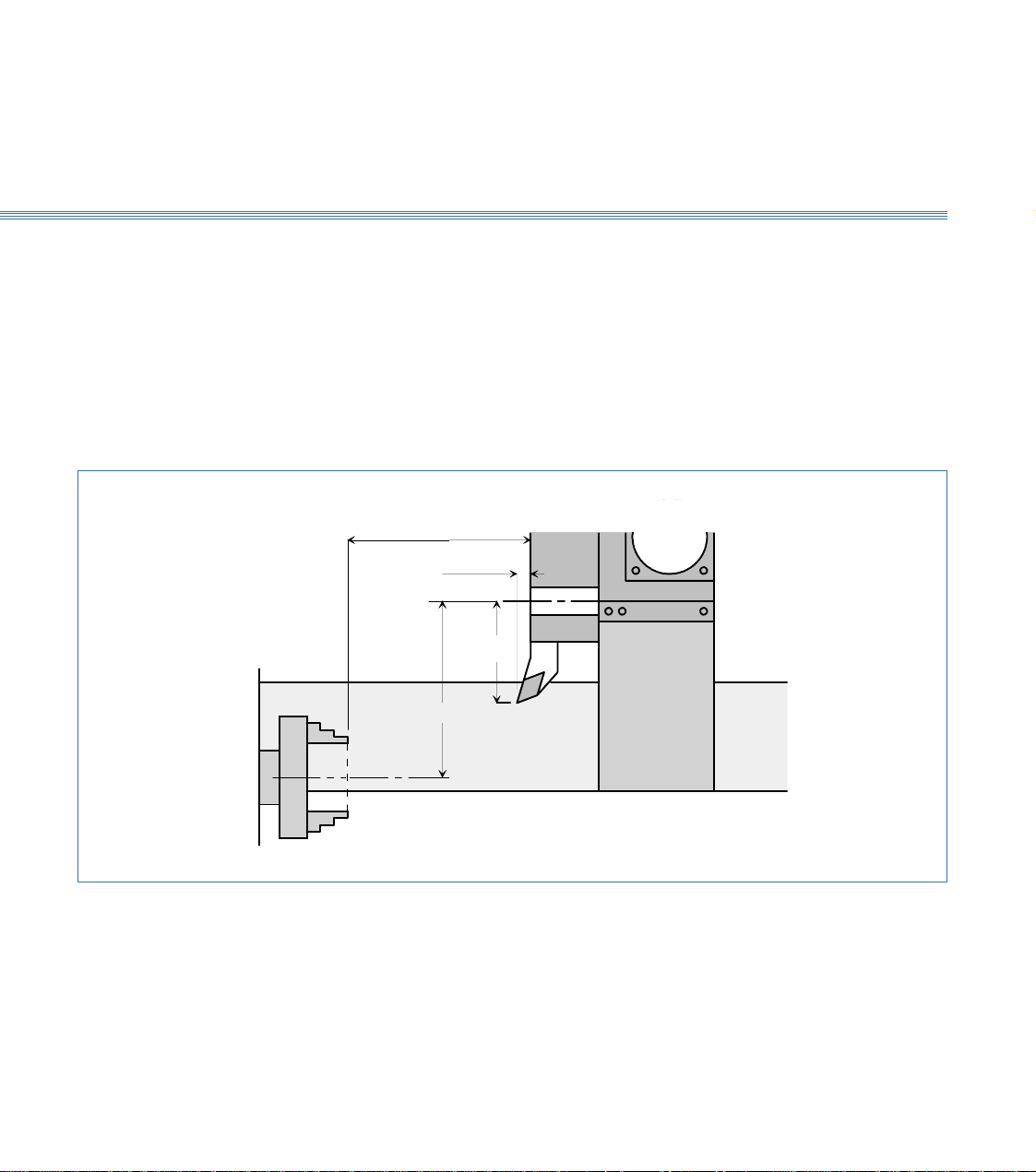
Tool Offsets: The Tool Z offset is the distance from the Turret Disc front face to the Tool Cutting
tip point.
The X offset is the distance from the centreline of the internal tool bores on the turret
to the Tool Cutting Tip Point (therefore theoretically all drills should have an X offset
of Zero).
The X offset is always twice the measured distance because the Boxford software uses
X values specified in Diameter (not radius).
Datum Z Value
Centre Line
of Internal
Tool Holder
Figure 3.2 Turret
Tool Z Offset
Tool X Offset
Datum X Value
Centre Line of Spindle
TURRET
Page 15
Boxford 160 TCL
Machines with Quick Change Tool Posts:
From the machines Home Position, the Machine Z Datum is the measured distance from
the front face of the chuck jaws to the front face of the machine cross slide as shown in the diagram
below. (figure 3.3)
The Y Datum is the measured distance from the spindle centreline to the bottom face of the tool
post mounting plate.
Tool X Offset
Axes and Tooling
3.1
Tool Z Offset
Centre Line of Spindle
Datum Z Value
Datum X Value
Figure 3.3 Quick Change
Tool Offsets: The Tool Z offset is the distance from the Cross Slide front face to the Tool Cutting
tip point.
The X offset is the distance from the bottom face of the tool post mounting plate to
the Tool Cutting Tip Point.
The X offset is always twice the measured distance because the Boxford software uses
X values specified in Diameter (not radius).
Page 16
Boxford 160 TCL Axes and Tooling
3.1
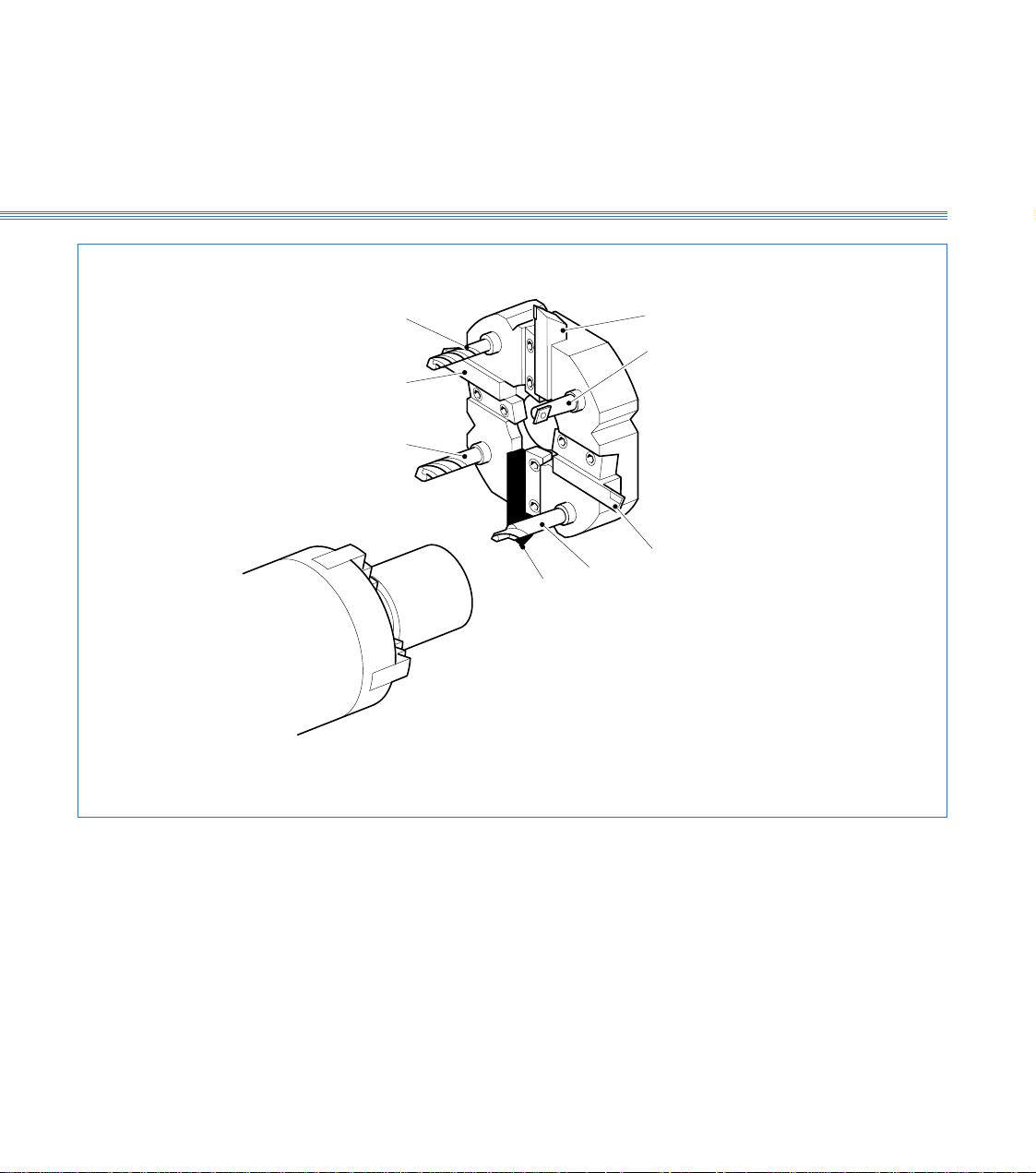
External tools: 1, 3, 5, 7
Internal tools: 2, 4, 6, 8
Figure 3.4 Turret Tool Positions
4
3
2
8
1
Machines without homing switches:
1: Reference tool
7: Second tool
5
6
7
Page 17

Boxford 160 TCL
Axes and Tooling
3.2
3.2 Turret (Figure 3.4)
The turret is a motor driven, disc type toolpost with positions for up to eight tools, four
external and four internal; each position is numbered.
Tools can be accessed by indexing the turret using the TURRET INDEX push button
on the machine controls or from the software.
Fitting Tools
Setting Tool Height
External tools are secured in radial slots by tapered clamp blocks held by two fixing
screws. Longitudinal positioning is achieved by pushing the tool towards the turret
centre so that it touches the location stop. Internal tools are secured in their predrilled
holes with tubular toolholders and two sunken screws.
This will normally have been set at the factory and should require no adjustment. If
it is found to be incorrect it is recommended that a Boxford service engineer is called.
However it is permissible to adjust it by putting a tool into the working position, then
inserting packing as appropriate between the turret toolpost and cross-slide. If this does
not achieve correct tool height, or other tools heights are still incorrect, contact the
factory.
Page 18
Boxford 160 TCL Axes and Tooling
3.3
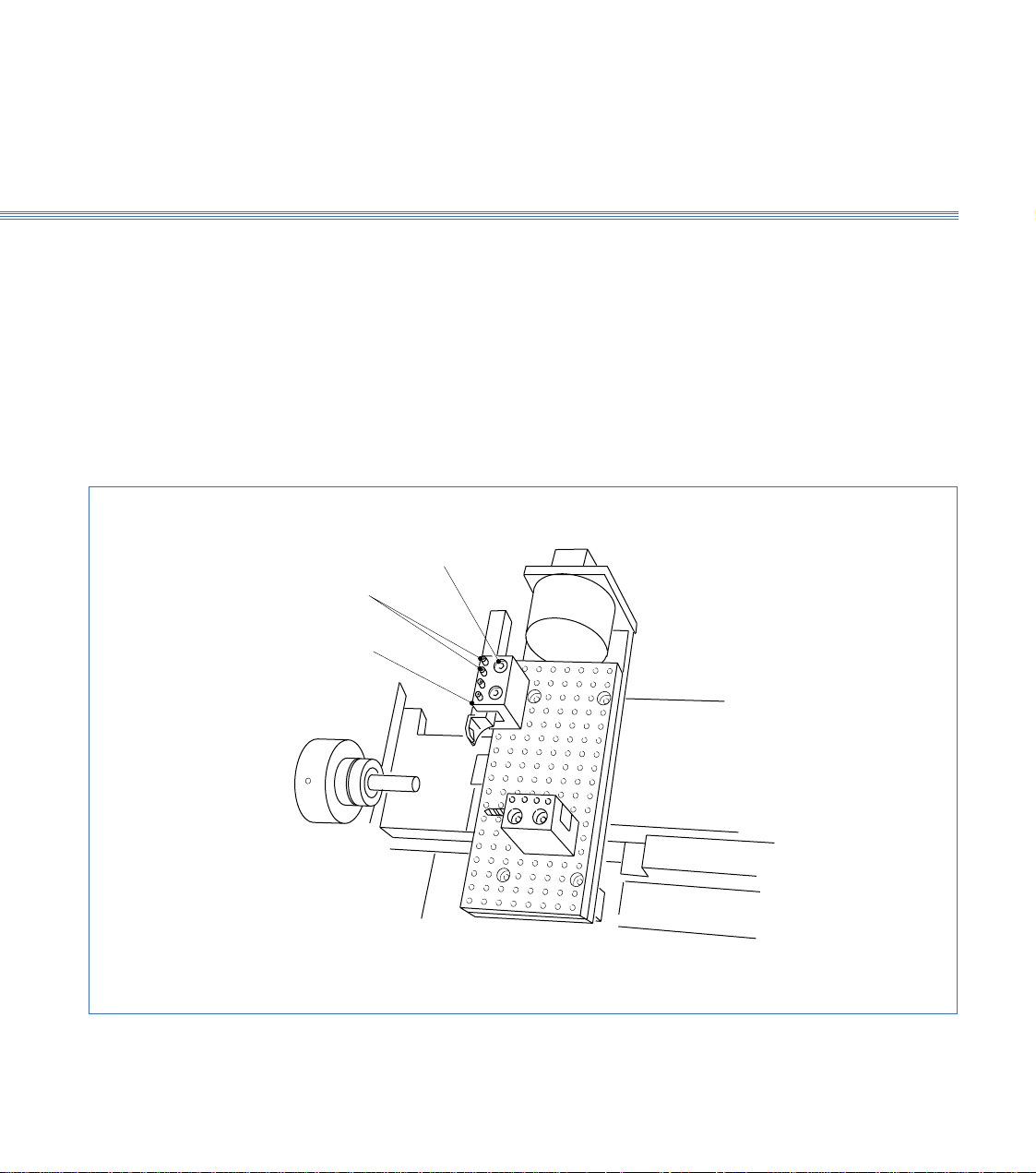
3.3 Quick Change Toolpost
Fitting Tools
(Figures 3.5 and 3.6)
The quick change toolpost has two slots to provide for convenient and rapid manual
tool changing. A toolholder with a tool already secured in it by the four securing screws
is placed into the shaped slots which provide instant positive location, and is rigidly held
there by tightening the single clamping screw, using the clamp screw key provided. The
toolpost will only accept a single toolholder at a time. External tools are fitted to the
X axis slot while internal tools use the Z axis slot.
A quick change toolpost can be fitted to the lower section of the X-axis cross slide in
addition to a gang plate.
Fit the LH turning tool into the standard flat bottomed toolholder by tightening the
four securing screws onto the tool shank. The tool should protrude approximately
20mm (0.75in) from the toolholder face. Keep this dimension consistent for all the
external tools. Put the toolholder into the toolpost and lock it into position using the
clamping screw.
Figure 3.5 Quick Change Toolpost
Tool Clamping Screw
Tool Tool Securing Screws
Page 19
Boxford 160 TCL
Axes and Tooling
3.1
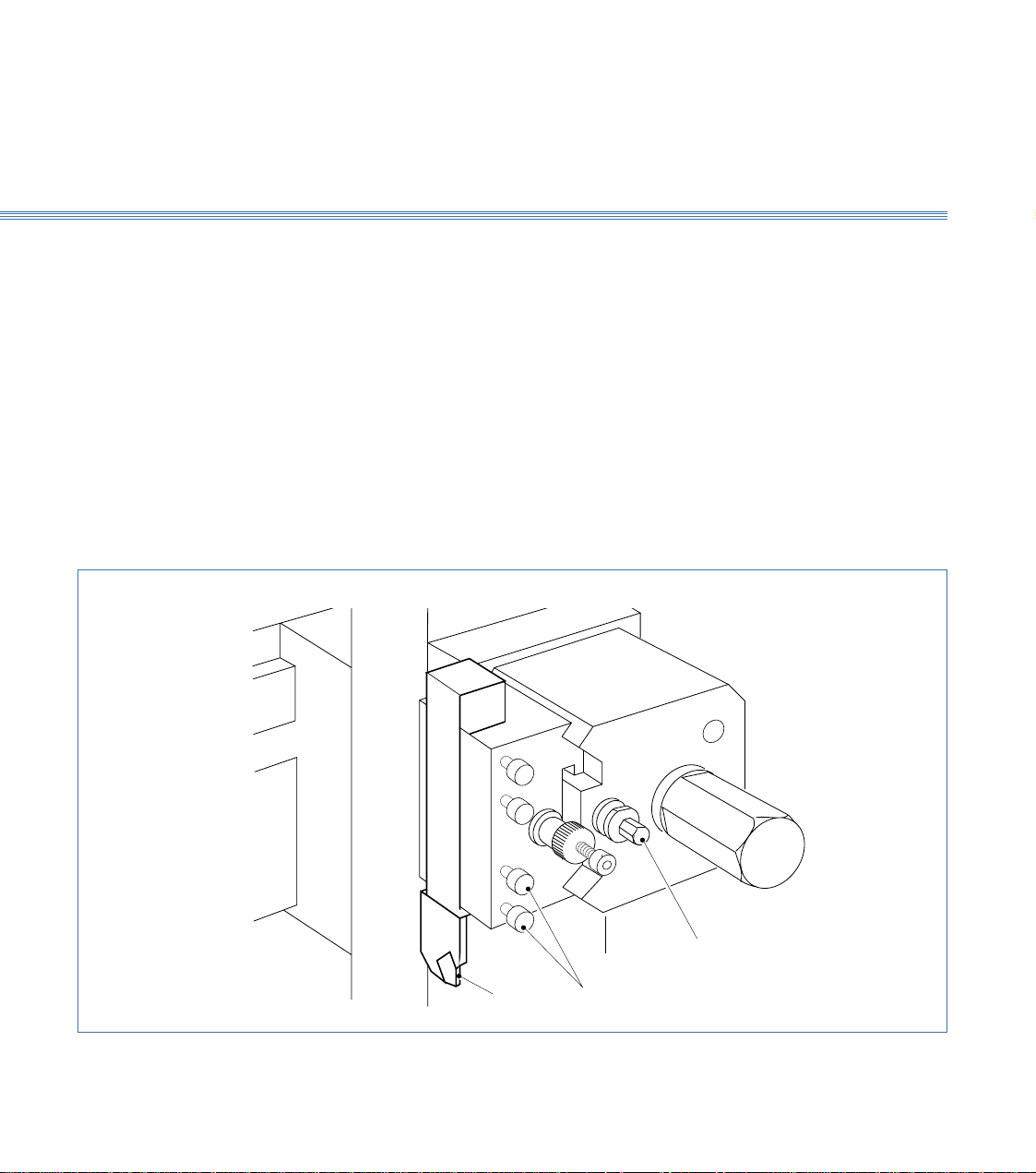
Height Setting-External Tools
1. Visually check the height to the workpiece centre point. The actual height from the top
2. To adjust the height slacken the toolpost clamp screw and the centre height adjustment
3. Check that the tool is exactly on the centre line by taking a light facing cut on the end
Tool
Clamping
Screw
Refer to Section 10 Manual Machining to move the tool manually to set the tool height,
which is checked by taking a light facing cut on the end of the workpiece. If adjustment
is needed to centre the tool, use the centre height adjustment screw on toolholder as
follows:
of the cross slide to the centre of the spindle is stamped on the left face of the bed
adjacent to the headstock cover.
Note:
Do not confuse this value with the machine serial no. which is also stamped here.
screw. Turn the knurled adjustment knob clockwise to raise the tool, anticlockwise to
lower it.
When the height is correct tighten the Allen screw then tighten the toolholder clamp
screw.
of the workpiece, using spindle in reverse direction. Repeat adjustment above as
necessary.
Constant
Centre Height
Adjustment Screw
Figure 3.6 Tool Fitting and Adjustment
Tool Securing
Screws
Page 20
Boxford 160 TCL Axes and Tooling
3.3
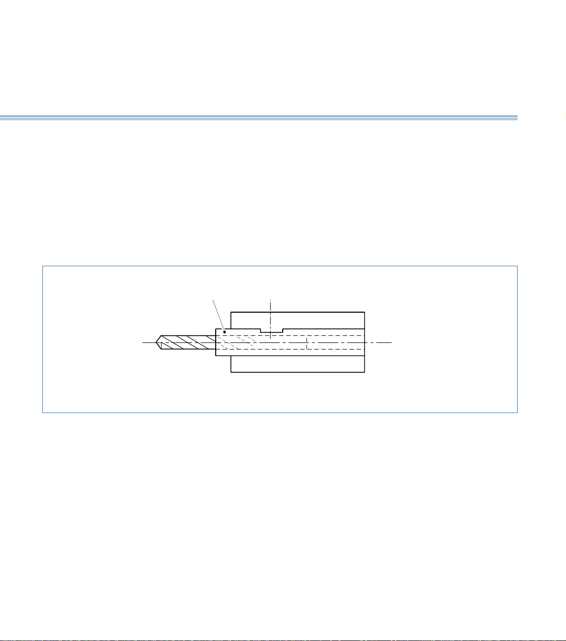
Height Setting - Internal Tools
Figure 3.7 Internal Tool Fitting Detail
These tools can be fitted directly into the V location toolholders intended for use with
the drills. Although not essential, it is better if they are located into a tubular holder.
This can easily be made as shown in Figure 3.7.
Put a toolholder with its tool on to the toolpost and set the centre height to the
workpiece centre line exactly as for external tools. Repeat this procedure for all of the
tools.
Drill Tube
Page 21
Boxford 160 TCL
Axes and Tooling
3.4
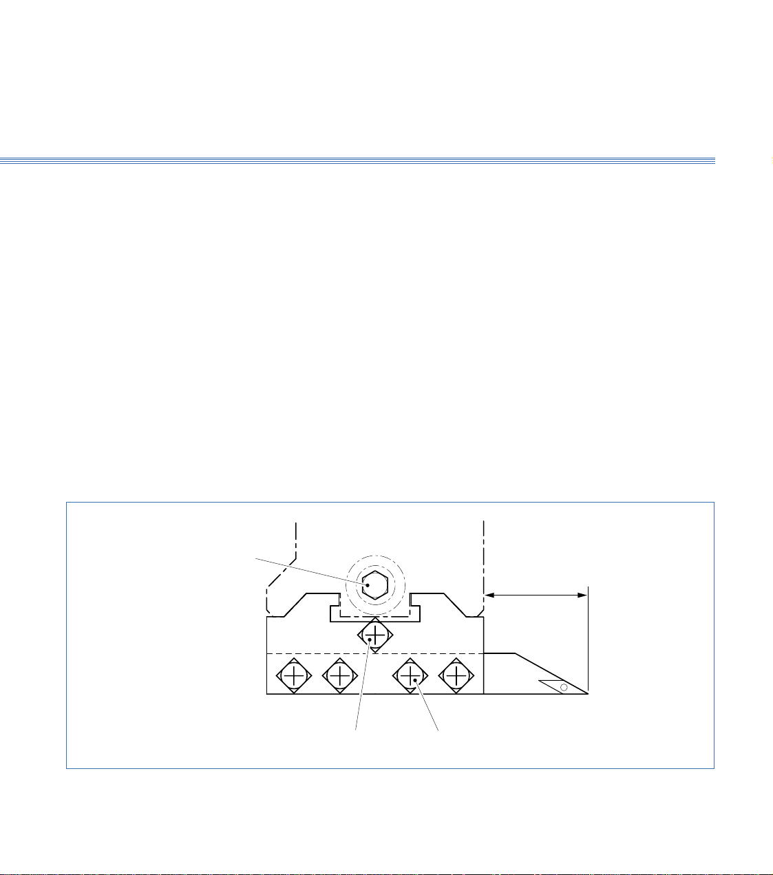
3.4 Gang Plate (Figure 3.8)
This is a plate with drilled holes enabling up to three simple channel shaped toolholders
to be clamped on to it. Tool positions are free, limited by hole line-up between
toolholder and gang plate and by ensuring that every tool mounted can reach the work
over the required range without fouling anything or causing other tools to foul
something.
Fitting the Tools
Setting Tool Height
Select a tool position and fit the channel toolholder using the securing screws. Clamp
the tool into it with the four clamping screws.
There is no tool height setting adjustment provided as this is pre-set at the factory. If
correction is needed, contact the factory.
Securing
Screws
Clamping
Screws
Channel
Toolholder
Figure 3.8 Gang Plate
Page 22

Boxford 160 TCL Axes and Tooling
3.5
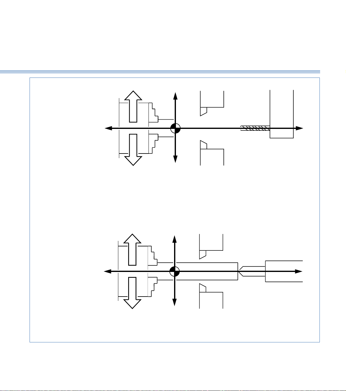
3.5 Spindle Rotation and Tool Orientation
Rotation
(Figure 3.9)
Tool Orientation
The spindle can run forward (anticlockwise when viewed on chuck jaws) and in reverse
(clockwise when viewed on chuck jaws). Direction and speed of rotation are controlled
either by the SPIND FWD/SPIND REV buttons on the machine control panel (refer
to Installation and User Manual Section 6 Machine Controls) or by means of M codes
(M03 = Forward and M04 = Reverse) selected from software.
For machining a workpiece held in the chuck with the tool fitted in the normal way,
i.e. with the cutting edge uppermost, the direction of rotation is as follows:
Direction M Code
External turning, toolholder at back Reverse M04
External turning, toolholder at front Forward M03
Internal turning Forward M03
If tools are fitted upside down, take care to select the appropriate direction of spindle
rotation.
Once the initial tool is specified, which then sets the direction of rotation, ensure that
all subsequent tools are fitted in the same orientation to avoid the need to reverse the
direction of rotation at tool changes while running a program.
Page 23
Boxford 160 TCL
Axes and Tooling
3.5
WORKPIECE IN CHUCK
REVERSE
+X
Tool holder at back
-Z
FORWARD
USING TAILSTOCK POSITIVE X VALUES ONLY
REVERSE
-X
+X
Tool holder at front
EXTERNAL TURNING
+Z
INTERNAL TURNING
-Z
FORWARD
-X
NEGATIVE X VALUES ONLY
Figure 3.9 Spindle Rotation and Tool Orientation
+Z
Page 24
Boxford 160 TCL Axes and Tooling
3.6
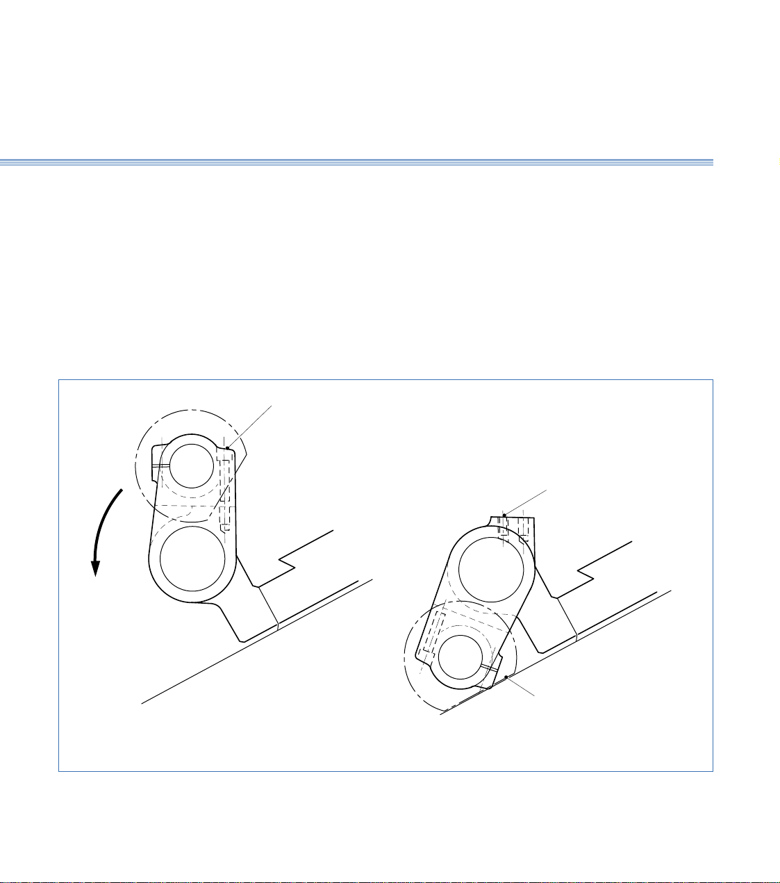
3.6 Tailstock (Figure 3.10)
The tailstock is bolted to the main slide. The upper part can be rotated about a
longitudinal axis to its working or parked positions. When not required, the upper part
is swung down and locked into its parked position to allow the toolholder its full travel
along the Z axis. The tailstock contains a quill to hold a centre, and is adjusted manually
in the Z axis.
Position Changing
and Securing
Two fixing screws secure the two halves of the tailstock rigidly into the working
position.
Removing these screws allows the top half of the tailstock to be swung down to rest
against the machine frame. This exposes a sunken Allen screw for securing the parked
tailstock section in place.
Fixing Screws
Figure 3.10 Tailstock
Locking Screw
Flat on
Handwheel
Page 25

Boxford 160 TCL
Axes and Tooling
3.7
3.7 Chuck
A manual or pneumatic chuck may be fitted. Pneumatic chucks are operated either by
using the CHUCK OPEN/CHUCK CLOSE pushbuttons on the machine control
panel (refer to Installation and User Manual Section 6 Machine Controls) or from
within software by use of appropriate M code (M40 = Open, M39 = Close).
Unless specified otherwise, pneumatic chuck jaws are prebored at the factory to 20mm
diameter. Should work with larger diameter workpieces be undertaken, the pneumatic
chuck jaws can be bored out to avoid the need to purchase another pneumatic chuck,
as follows:
1. Press the CHUCK CLOSE button and set the jaws to position to provide
sufficient material for boring. To move the jaws unfasten the two screws in the jaws,
raise the jaws from the serration plates and position them accordingly, then refasten
the screws ensuring that the jaws are equi-distant from the centre line of the chuck.
2. Make a washer 1mm thick with bore the same diameter that the chuck is to be bored.
The outside diameter of washer can be 30mm.
3. Press the CHUCK OPEN button.
4. Bore out the face of the jaws 1mm deep, 30.12mm diameter (0.12mm bigger than the
outside diameter of the washer).
5. Place the washer on to the machined jaw face and press the CHUCK CLOSE button
to clamp the outside diameter of the washer.
6. Revolve the chuck forward at approximately 2000 rev/min.
7. Bore out the jaws using the washer bore as a gauge. Use the axis control buttons to
provide tool movement with the FEED knob set to 75%.
8. When boring is complete stop the spindle and press the CHUCK OPEN button to
release the washer.
Page 26
Boxford 160 TCL
Axes and Tooling
3.8
3.8 Tool Libraries
The 160 software provides a Tool Data Library which enables details of tooling and
offsets to be entered and a Tool Library from which tools can be selected for inclusion
in the Tool Data Library. The library is set up by means of a tooling menu.
Before attempting to set up the tooling for the first time, view the libraries and the
tooling menu to become familiar with the details, as follows:
1. Switch on the PC, run the 160 software.
Tool Data Library
2. From the Simulation and Manufacture software main menu, select MACHINE and
then Tools.
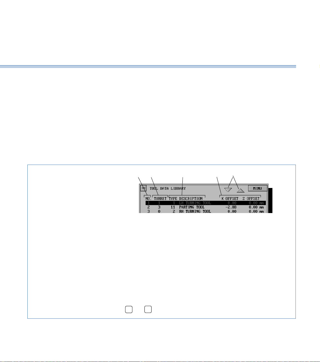
The screen shows the Tool Data Library, (Figure 3.11). Practice selecting tools using
the mouse and keyboard.
1 2 3 4 5
1. Tool number used by CNC program to select required tool
2. Tool position on Turret (not used with Gang plate or Quick change tool
holder)
3. Tool type and description (selected from tool catalogue)
4. Tool offsets
5. Scroll buttons
To select a tool:
Using a mouse
Click on the scroll buttons (5) to highlight the required tool,
point to required tool and click mouse button.
Using the keyboard
Press ➔ or ➔ to highlight the required tool.
Figure 3.11 Tool Data Library
Page 27
Boxford 160 TCL Axes and Tooling
3.8
Tooling Menu
Tool Library
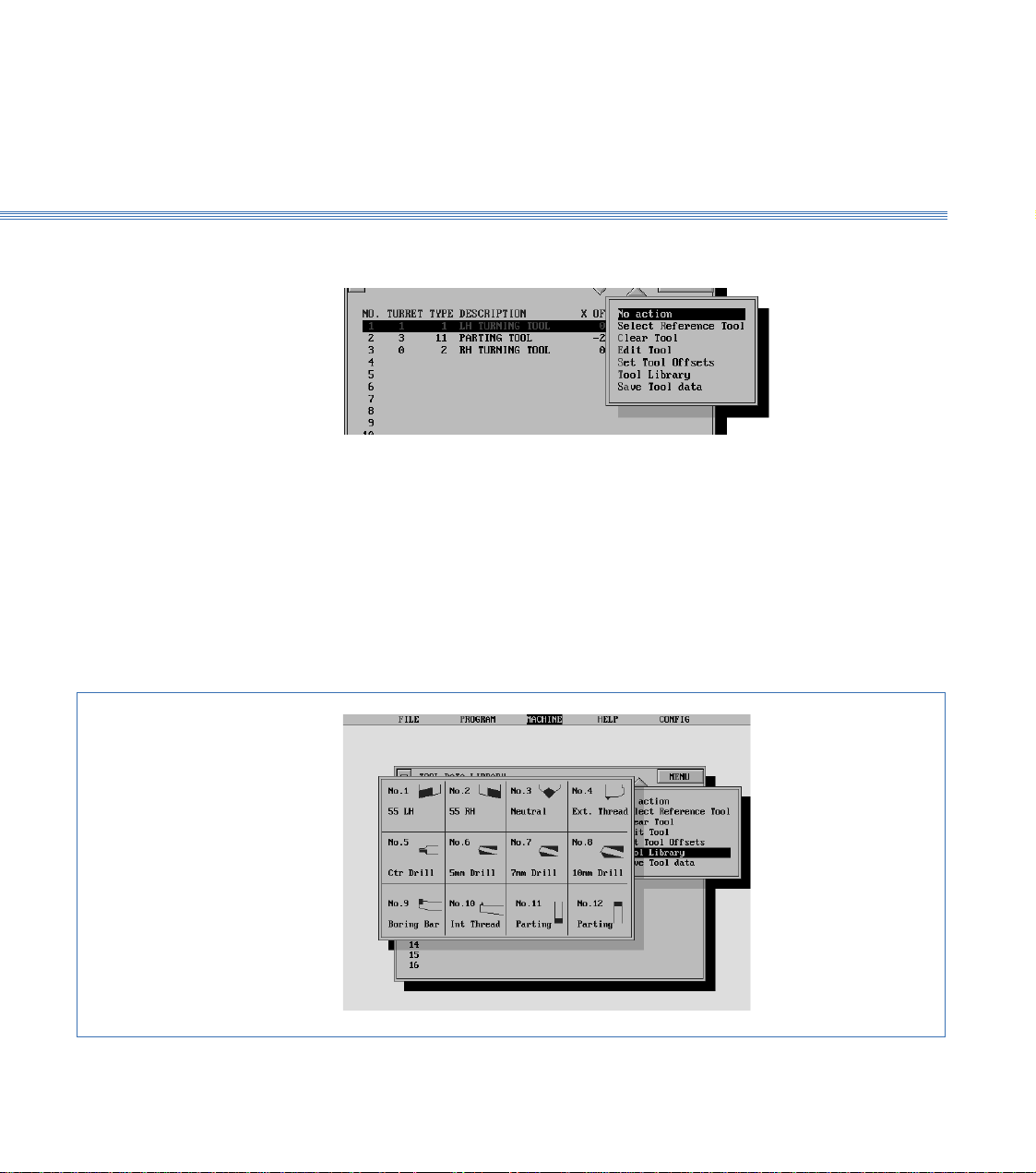
3. Select MENU to display the tooling menu:
The use of these options for setting and editing the Tool Data Library is detailed later
in this section.
Note:
After setting up or editing the library, always select Save Tool data.
4. From the tooling menu, select Tool Library.
The screen shows the Tool Library, (Figure 3.12).
Turn off the Tool Library display to reveal the Tool Data Library.
Figure 3.12 Tool Library
Page 28

3.9Axes and ToolingBoxford 160 TCL
3.9 Setting Up
Note:
A billet of the appropriate size will be required for this procedure. In order to run the demonstration
program, a LH turning tool and a parting tool are required. To run the program, set up the LH
turning tool as the first tool and the parting tool as the second tool in the following procedure.
Fit Tooling
Configure Software
Set Datum Position
1. Fit the required tools into the toolholding system supplied.
With the quick change toolpost, fit the first tool required. After setting the offset of
the first tool, it will be necessary to substitute the next tool before setting its offset.
If the toolholder is too close to the chuck to allow the tools to be fitted, move the
toolholder away from the chuck under manual control, (see Section 10 - Manual
Machining).
2. Check that the POWER RESET button on the machine control panel has been pressed
to initialise the machine.
3. Run the Simulation and Manufacture software. From the main menu select CONFIG
and then Program.
4. On the PROGRAM display, set UNITS MODE to the units required for tool offsets
and programming.
5. If a turret is fitted, select CONFIG and then Hardware, and check that TURRET is
set to FITTED.
Note: It is only necessary to set the datum position when the machine is first installed, or if the original
setting is lost. In order to set the datum position, the information supplied with the machine will be
required; this information consists of an X and a Z axis measurement.
6. From the main menu, select MACHINE and then Datum Position. The screen
shows:
Page 29

Boxford 160 TCL 3.9 Axes and Tooling
Enter the X and Z axis measurements supplied with the machine, and select
SAVE
The screen returns to the main menu.
7. From the main menu, select MACHINE and then Tools to display the Tool Data
Library. Defaults of the first tool will be highlighted, for example:
Check the settings. If they are correct, continue at step 15 to set the second tool.
For the demonstration program, the settings should be as shown.
8. Select the tool to be edited by clicking on it with the mouse, or on the keyboard use
the
➔
keys to highlight the required tool and press Return.
➔
9. The screen shows the tool editing display, with the first item (Tool type) highlighted,
(refer to Figure 3.13).
Edit the display to show the required Tool type (and Turret position if applicable). Do
not edit the offsets.
10. Select
MENU
, and then Set Tool Offsets.
11. The screen shows:
.
Page 30
3.9Axes and ToolingBoxford 160 TCL
Follow the instructions, selecting AUTO mode on the machine control panel and
pressing both X axis buttons simultaneously, then both Z axis buttons, to home the
axes.
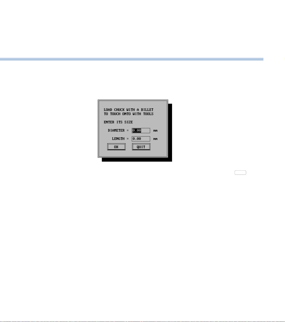
12. When the axes are homed, the screen shows:
Fit a billet into the chuck. Enter its diameter and length, and select
Return.
13. The screen shows the tool offsets setting display, (Figure 3.14).
On the machine control panel, select MANUAL mode. Using the X and Z axis buttons,
follow the instructions appropriate to a drill or other type of tool to position the point
of the tool on the reference diameter (the periphery of the billet).
OK
or press
Page 31

Boxford 160 TCL 3.9 Axes and Tooling
OK
1
2
1 To check tool type, press Escape or select
MENU
2 To check tool position, for Turret only, refer to Figure 3.2
3 Offsets for reference tool are zero.
and Tool library to view tool library.
To edit tool details:
Type required number in highlighted box
Press Return to accept last entry and highlight next box
When last box is highlighted, press Return: highlight will disappear
Press Return or click on
Figure 3.13 Tool Editing Display
CANCEL
to turn off display
3
, then select
Page 32

3.9Axes and ToolingBoxford 160 TCL
TOOLS OTHER THAN DRILLS
Tool position on axes
Tool position on axesDRILLS
Figure 3.14 Tool Offsets Setting Display
Page 33

Boxford 160 TCL 3.9 Axes and Tooling
Set Additional
Tool Offsets
14. When the tool is in the correct position, select
ACCEPT
. The screen shows:
Use the X and Z axis buttons to touch the point of the tool on the end of the billet,
and select
ACCEPT
.
15. The screen again shows the Tool Data Library.
To set the offset of the next tool, fit or index the tool and repeat the procedure from
step 7.
Note:
For setting the offsets of the second and any subsequent tools, it will not be necessary to home the axes
or enter the billet dimensions (steps 11 and 12).
When the offsets of all the required tools have been set, either select
then Save Tool Data, or click the 'off' button of the Tool Data Library display. If the
'off' button is clicked, the screen shows the message:
MENU
`and
Click on
or press Return to save the offsets.
YES
Page 34

4Main Front End Menu
When the Boxford CADCAM package is started, the Main Front End Menu screen
below is shown.
This menu is the central manager of the CADCAM tools within the Boxford TCL
package.
File Import &
Administration Functions
Program Simulate, Manufacture
and Machine Tool Driver
CAD and CAM Processor Exit to Windows Desktop
Page 35

Boxford 160 TCL
4 Main Front End Menu
In Standard User mode this menu accesses the File import filter.
In Administration mode (See section 7) additional CAM processor data settings can be
accessed and modified.
Accesses the Integrated Computer Aided Design package and CAM processor. (See
section 5)
Accesses the G&M program Simulator, Editor, Writer and Machine Tool driver. All
the configurations for connecting the TCL machine to the PC are set in this section
of the package (See Installation & User Manual).
Exits to the Windows desktop.
Page 36

New Programs
Existing Programs
CAD and CAM ProcessingBoxford 160 TCL
5 CAD and CAM Processing
5.1 Functions
The CADCAM programming features of the software provide the following
functions:
A new component is created by producing a profile on screen using the
integrated CAD system. When the profile is complete, it is processed by the
CAM system which converts it into a CNC program and saves it. The
appropriate G and M codes are included, and speeds, feeds, roughing cuts
and tool changes are incorporated into the program automatically.
Profiles stored in a CAD format can be edited. Programs created by the
CAM processor are presented in CNC format using absolute co-ordinates.
Programs created by the CAM processor and stored in a CNC catalogue can
only be viewed and edited in CNC format.
Page 37

Boxford 160 TCL CAD and CAM Processing
5.2
5.2 Information Required
To create a new CAM program you will need the following information:
1. Drawing:
The work datum is the centre of the right hand end of the bar. Since the
profile is symmetrical about the centreline of the bar, only positive X co-
ordinates need be dimensioned. All Z co-ordinates are negative, measured
from the end of the bar:
dimensions required
-Z
+X
datum
The drawing should make allowance for completing the chuck end of the
workpiece. If threads are incorporated, make allowance for undercutting
between the end of the thread and any shoulder.
For ease of programming, mark the co-ordinates of the start and end points
of each element of the profile as shown in the example in 5.4.
2. Tools Used:
Choose the appropriate tools for each machining operation, and set up the
tooling as for CNC machining.
3. Details of the billet:
Outside diameter
Inside diameter (if the billet is hollow or a tube)
Length
Hole Depth
Material (aluminium, brass, mild steel or plastic).
Page 38

CAD and CAM ProcessingBoxford 160 TCL
5.2
4. Program Name:
A name for your program (This must be a valid filename, without a file
extension.
5. Configuration Settings:
The STANDOFF option automatically adds the depth of cut to a 2mm
standoff (clearance between tool and workpiece) when using canned cycles.
This option, and other configuration settings, can be activated by selecting
CONFIG - Program from the main menu of the Simulation and Manufacture
software and making the required settings.
Page 39

Boxford 160 TCL CAD and CAM Processing
5.3
5.3 Creating a CAD Profile
Check Configuration
Input Program Details
1. From the main simualtion and manufacture menu, select CONFIG -
Program, and select STANDOFF if required.
2. From the main Front End Menu, select the CAD icon. To start a new profile,
select File - New or select the icon
Note:- If you want to open an existing file, select File - Open, or the icon,
and locate the required file.
The window below is displayed.
Input the details as follows:-
DIMENSIONS:- As required.
UNITS:- Metric of Imperial.
COMPONENT INFORMATION:- This is a field which allows more
detailed information about the profile to be entred alowing easier
identification. It is NOT the program file name.
CREATED BY:- Allows the user to name stamp their work.
When the information is correct, OK is selected. This brings up the CAD
Window.
Page 40

CAD and CAM ProcessingBoxford 160 TCL
5.4
5.4 CAD Window
The CAD program window provides a clear view of the current drawing,
various information areas, and a selection of icons with tools to cover the
most common drawing, editing and display functions.
Menu bar
Absolute
coordinates shows
the position of the
cursor relative to
the workpiece
datum (thecentre
of the component
front face)
Help message bar
Grid Snap
Grid Spacing
Tool bar
Status Bar
Billet area
Billet Information
Menu Selection
Menu items are normally chosen from the menu bar or the tool bar, using
the mouse (although keyboard alternatives are available). To choose a
menu item from the tool bar, position the pointer over the appropriate icon
and click the LH mouse button. Many items will cause the icon to stay
depressed until an alternative mode is selected from another icon.
Holding the mouse over an icon will bring up an icon Tool Tip.
Page 41

Boxford 160 TCL CAD and CAM Processing
5.4
Initial Set-up
Before starting to use the CAD system, a number of Initial Set-up steps must
be completed. Complete the following from the relevant menu:-
1. DRAWING TOOLS - SHOW GRID - Tick to show a drawing grid or untick
to clear.
2. CONFIGURATION - DEFAULTS - When in Administrator Mode (see
section 7 of this manual), the current Billet Information, Colours and Grid
Snap can be saved as the default setting for all New profiles. See below for
details.
From the Tool Bar:- 1. UNITS - Check the units. Specify Millimetres or Inches.
2. GRID SPACING - Specify the spacing for the Grid.
The default value is 1.00mm as shown. Along the Z axis the pitch of the grid
is equal to the value set. Along the X axis the pitch is half the set value, since
each element of the profile is mirrored below the centreline of the workpiece.
For example, setting the grid snap to 5.00mm produces the following grid:
+X
-Z
centreline
2.5mm
Note:
5mm
The setting can be edited later during the creation of a profile if required.
3. BILLET DIMENSIONS - Check and modify the billet dimensions.
4. COLOUR SELECTION - Modify the screen display colours.
Printing Prints the currently displayed view of the complete billet and any displayed
dimensions.
Page 42

CAD and CAM ProcessingBoxford 160 TCL
5.5
5.5 Drawing Aids
Drawing Aids The tool bar contains a number of drawing aids which are active when
selected (icon is highlighted).
Undo - Undoes the last drawn or edited entity.
Delete - Deletes the currently selected entity.
Redo - Redoes the last drawn or edited entity.
Zoom Window - Zooms in on a user defined window.
Zoom In - Performs a quick and simple zoom in facility on the billet
area currently being worked on.
Zoom Out - Performs a quick and simple zoom out facility on the billet area
currently being worked on.
Grid Snap - Toggles locking the cursor movement to the grid on and off.
Profile View - Toggles the billet view between half and full.
Advanced Zooms A number of zooms to a specified percentage value can be selected from
the drop down menu.
Alternatively, FIT can be selected to fit the drawn entities and billet to
the current screen area.
Status Bar
When defining points with the mouse, the status bar provides dynamic co-
ordinate readouts for the X axis (diameter reading), Z axis and Radius when
applicable.
The currently active Zoom, Snap and Drawing Tool are displayed.
Node Position
Hovering the mouse cursor over a node (point) will display the node
number and absolute co-ordinates.
Page 43

Boxford 160 TCL CAD and CAM Processing
5.6
5.6 Drawing Tools
Drawing Tools
The Tool Bar contains a variety of drawing tools.
The following drawing tools require points to be defined with the mouse
(using the grid).
Help and Prompts Help for each icon is displayed on the Help Message Bar to aid the user.
Straight Line - Defines a single straight line - The Start and End point are
specified. The start point MUST be the end point of the last drawn
entity. The system prevents any point other than this from being defined
as the start point.
Arcs - Draws a single arc - The Start and End point are specified. The start
point MUST be the end point of the last drawn entity. The arc direction and
radius is set with the mouse amd fixed with the LH button. After drawing
a single arc, the system reverts to Straight Line mode.
Continuous Path - Draws a series of connected straight lines and/or arcs.
The End point of each entity is defined with the LH button. Line and Arc
mode are toggled between using the RH button. This mode is the default
drawing mode for all new drawings and will be familiar to users who have
worked with previous versions of Boxford software. Press ESC to exit.
Thread- Draws external and internal threads along the Z axis - The Start and
End point are specified follwed by the Pitch and Hand in the dialogue box
shown below.
Note: If the Thread tool is greyed out, the system has detected that due to lathe machining
conventions, the next entity can not be a thread. If a right hand thread is selected,
the two dotted lines represent the minimum undercut required for the specified
thread. There must NOT be any entities drawn in this area.
Fillet - Draws a fillet between two perpendicular lines - The fillet radius is
entered and the required corner intersection selected.
Chamfer - Draws a 45° chamfer between two perpendicular lines - The
chamfer distance is entered and the required corner intersection selected.
Page 44

CAD and CAM ProcessingBoxford 160 TCL
5.6
Co-ordinate Entry As an alternative to defining an entity using the mouse, a coordinate entry
sytem is available. Note:- Co-ordinates not on the current grid can be
defined.
Co-ordinate Entry - Defines Lines and Arcs using a coordinate entry system.
The following dialogue box of options is available. (Note:- the Absolute
point displayed is the end position of the last defined entity. If an arc is
required, define the arc direction CW(clockwise) or CCW (counter clockwise)
and the Arc radius. Ensure a valid arc radius that can pass through the start
and end point is defined.
To enter a number of entities,tick the 'Enter more points' check box.
Absolute Point (x,z): - Define the end point of the entity as an absolute
coordinate from the billet datum (centre of front face).
Length and Angle: - Define the cord length of an entity and the angle as
shown in the diagram below. See next page for angle conventions.
C
o
r
dLe
n
g
t
h
End Point
0°
L
ine
le
g
n
A
o
90°
r
A
r
c
Start Point
Page 45

Boxford 160 TCL CAD and CAM Processing
5.6
Angle Conventions
For all co-ordinate entries requiring an angle, the conventions shown in the
diagram below should be used.
0°
90°
0°
90°
180°
90°
90°
0°
270°
180°
270°
0°
90°
270°
0°
Absolute Point (x,z): - Define the end point of the entity as an incremental
move from the end of the last entity co-ordinate.
Displace X and Angle: - Define an incremental move in X and the angle as
shown in the diagram below. Note angles should be to the conventions
shown above.
End Point
XinØ
0°
le
g
An
L
i
n
e
o
90°
r
A
r
c
Start Point
Displace Z and Angle: - Define an incremental move in Z and the angle as
shown in the diagram below. Note angles should be to the conventions
shown above.
Z
L
i
End Point
0°
n
eo
e
l
g
n
A
r
A
r
c
90°
Start Point
Page 46

CAD and CAM ProcessingBoxford 160 TCL
5.6
Auto Dimensioning The Auto Dimensioning function toggles between three modes.
Please note:- auto dimensioning is an extremely difficult operation for the
system to complete on the large variety of profiles that can be defined on the
CAD system. In some cases the position of the dimension will be a
compromise to allow all dimensions to be displayed.
1. Standard Mode - Dimensions the billet only (default start up mode).
2. Incremental Mode - Dimensions all points on the profile with the Z
dimension relative to the previous and next point as shown below.
2. Absolute Mode - Dimensions all points from the billet datum.
Page 47

Boxford 160 TCL CAD and CAM Processing
5.7
5.7 Editing Tools
Editing Node Positions
Editing Entities Moving a mouse cursor over an entity and clicking the RH mouse button
Moving the mouse cursor over a node (point), pressing and holding
the Right Hand mouse button, allows the node to be dragged to a new
position. Releasing the RH mouse button fixes the node to the new position.
A node can also be moved using the co-ordinate entry system. See the
section 'Editing Entities' - Properties below.
will highlight the entity and display the dialogue box shown below.
Depending on the type of entity selected, some of the options will be greyed
out as they are not applicable to to the specified entity.
Insert Node - Inserts a node at the midpoint of the entity which adds an
additional straight line entity. Note if this option is used on an ARC, the arc
will be converted into two diagonal lines as shown below.
Insert Fillet - Inserts a fillet between the selected entity and following entity.
Thr radius is specified as shown below.
Page 48

CAD and CAM ProcessingBoxford 160 TCL
5.7
Delete Object - Deletes the selected object, connecting the end point of the
previous object to the start point of the next object as shown in the diagram
below.
Convert to Line - Converts an arc into a diagonal straight line.
Convert to Arc - Converts a diagonal straight line into an arc.
Convert to Thread - Converts a horizontal straight line into a thread.
The pitch and hand of thread are entred as shown below.
Note:- If a horizontal straight line does not have this edit option available,
it is because it is not in a suitable position, in relation to other entities within
the profile, to be threaded.
Modify the Arc Radius - Unlocks the arc radius allowing it to be re-specified
with the mouse position and fixed with the LH button.
Properties - Displays the properties of the entity. The co-ordinates diplayed
are the end point of the entity. Co-ordinates can be modidifed to move the
end point to a new (valid) position. Arc radii and/or direction can be
modified. See section 5.6 - Drawing Tool - Co-ordinate Entry for specific
details on co-ordinate conventions.
When an entity has been highlighted with the RH mouse button, the
properties field is also accessible through the icon on the tool bar.
Page 49

Boxford 160 TCL CAD and CAM Processing
5.8
5.8 3D Renderer
At any point during the design of a profile, a 3D rendred image can be
viewed and manipulated.
'Launch 3D Render' is selected from the 'View' menu.
If the profile has not being named and saved, the user is prompted to do so
at this point.
If the profile has been modified and not re-saved, the box below is shown.
Select YES to overwrite the old profile.
Select NO to abort and use the File - Save As option to rename the file before
launching the 3D Renderer.
The 3D Renderer window, as shown below, is launched.
Page 50

CAD and CAM ProcessingBoxford 160 TCL
5.8
The 3D Renderer defaults to an automatic animation mode which continually
spins the model around the vertical axis.
The user can overide the animation and manipulate the model with the tools
provided from the window menus. These are as follows.
Model Control Solid Render - Solid Renders the image as shown on the previous page.
Wire Frame Render - Diplays a wire frame image as shown below.. This can
be useful for speeding up the animation on computers which are close the
the required minimum specification.
Animate - Initiates the default automatic animation mode.
Freeze Animation - Stops the automatic animation allowing manual
manipulation of the model.
Print - Prints an image of the model in its current position. Textual model
data is also produced.
Copy Image to Clipboard - Copies an image of the model in its current
position to the clipboard for pasting into 3rd party packages. Note the black
background is converted to white.
Rendering Material Allows the shading of the model to be changed to represent Steel, Plastic, or
Wax. Wax is the default material.
Rotate Model Jogg Left, Jogg Right, Jogg Up, Jog Down - Joggs the model in the required
direction by one increment. Alternatively, use the keyboard hot key.
Home - Re-sets the model position to its home position.
Spin Left, Spin Right - Rotates the model around the Z axis (centre line). This
is a useful for viewing a screw thread.
Page 51

Boxford 160 TCL CAD and CAM Processing
5.8
Using the Mouse
In addition to the mouse menu and keyboard controls, the model can be
manipulated using the mouse.
Move the cursor over the model. Press and HOLD DOWN the LH mouse
button. The model can now be dragged to any position. To fix in the
required position, release the mouse button.
Examples of the positional possibilities are shown below.
Page 52

CAD and CAM ProcessingBoxford 160 TCL
5.9
5.9 Example (Figure 5.1)
Figure 5.1 shows a drawing of a component whose profile consists of
straight lines, arcs and a thread. The co-ordinates of the start and end points
of each element have been marked in the top half of the billet outline.
The straight lines and arcs can be machined with the LH turning tool (1) and
parting tool (11). To cut the thread it will be necessary to fit an external
threading tool and to add this to the Tool Data Library.
Start a new CAD Profile as detailed in 5.3 and use the File - Save option to
name it EXAMPLE. Refer to 5.4, 5.5, 5.6 and 5.7 for guidance in producing
the profile shown in Figure 5.1.
Co-ordinates shown in the format: X, Z
10mm x 0.75mm pitch RH
21,-39
17,-45
0,-45
Z -50
16,-29
21,-29
10,-14
10,-16
Figure 5.1 Example of Drawing for CAM Program
15,-9
8R 8R
X +25
8,-1
8,-4
0,0
Page 53

Boxford 160 TCL CAD and CAM Processing
1. Place the cursor in the top half of the billet outline.
2. A cross is displayed which is connected to the datum by a straight line:
5.9
3. Watch the co-ordinate display and drag the cross-hairs to set the end point
of the line in the correct position. The line will behave like a rubber band,
and X and Z co-ordinates of the display will change as the cross is moved;
when they read X = 8.00, Z = 1.00, select the LH mouse button. Ensure that
grid snap is set to 1.00mm or less.
4. The first line of the profile will remain on the display, and will be mirrored
by a symmetrical line in the bottom half of the billet outline if displayed.
Page 54

CAD and CAM ProcessingBoxford 160 TCL
5.9
5. Repeat this procedure to draw the next straight line of the profile, dragging
the cross to the end point of each line and checking the co-ordinate display
before selecting the LH mouse button:
If you make a mistake, select to erase the last line and repeat the
procedure.
Manual Input
Using the RH mouse button, select each object and selecte 'Delete Object'.
1. Select ; the screen will show the co-ordinate entry window:
The absolute co-ordinates of the end point of the last element to be drawn
are shown. Since no element has yet been drawn the co-ordinates are those
of the datum.
2. Enter the absolute co-ordinates of the end point of the first line: X = 8, Z =
-1, and select OK.
The first line of the profile will appear, mirrored by a symmetrical line in
the bottom half of the billet outline.
3. Repeat this procedure to set the end point of the next line of the profile:
X = 8, Z = -4
If you make a mistake, select to erase the last line, and repeat the
procedure.
Page 55

Boxford 160 TCL CAD and CAM Processing
5.9
Drawing Arcs
In Continuous Path Mode ,arcs are selected with the RH mouse button.
If the Arc Tool is selected from the tool bar, in addition to the procedure
detailed below, the start point must first be defined with a LH mouse click
over the end point of the last drawn entitiy.
An arc is drawn in three stages as follows:
1. Set End Points
Drag the cross to the end point of the arc. Check the co-ordinates on the
display. Adjust the position of the cross until the co-ordinates are correct,
and fix the position with the RH mouse button.
Drag to end point of arc (15,-9)
then release button
'rubber band'
Start of arc (8,-4) end point of last straight line
2. Select Direction and Radius
Move the cross away from the end point (1); the cross will be joined to the
end point by a straight line which is the tangent to the arc at the end point.
Swing the cross around the end point (2); the arc will switch from counter-
clockwise to clockwise, and the radius will vary as the cross is moved:
1
2
Clockwise arc
Counter clockwise arc
For the example, select a counter-clockwise arc and set the radius at
8.00mm. Check the co-ordinate display for the correct setting:
X = 15.00 Z = -9.00 ARC RADIUS = 8.00mm
Page 56

CAD and CAM ProcessingBoxford 160 TCL
5.9
3. Enter Setting
When the setting is correct, click the LH mouse button.
If you make a mistake, select to erase the arc, and repeat the procedure.
Draw the second arc, setting the end point at X = 10, Z = -14. Select a counter-
clockwise arc, and set the radius at 8.00mm.
Using the RH mouse button, select each object and select 'Delete Object'.
Manual Input
1. Select
2. The screen shows the co-ordinate entry window:
The X and Z co-ordinates shown are those of the end point of the last
element in the profile (A). Enter the co-ordinates of the end point of the arc
(B):
In the 'Arc Properties' section, shown below, select CCW (counter-clockwise)
and enter the radius of the arc. (For the example, enter 8.00mm).
8.00
B
A
3. Select OK: the arc will appear on the display, and will be mirrored by a
symmetrical arc in the bottom half of the billet outline.
Page 57

Boxford 160 TCL CAD and CAM Processing
AB
5.9
4. For the example, repeat the procedure to draw the second arc. Set the radius
to 12.00mm and the co-ordinates of the end points to X = 10, Z = -14:
10,-14
If you make a mistake, select to erase the last arc, and repeat the
procedure.
Drawing Threads 1. For the example, draw the next three straight lines of the profile in
preparation for adding the threaded section:
2. Select and then the start point of the thread, last point:
The cursor is locked to the horizontal plane. Move the cross to the Z co-
ordinate of the end-point of the thread (B) and fix with the LH mouse button.
Page 58

CAD and CAM ProcessingBoxford 160 TCL
5.9
3. The window below is shown.
Select left hand or right hand thread as required. For the example, select
right hand thread. Change the THREAD PITCH value if required, entering
either a pitch (metric units) or threads per inch (Imperial units).
For the example, set the pitch to 0.75mm
4. Select OK ; the specified thread will appear on the profile.
5. For the example, draw the remaining straight lines to complete the profile:
Page 59

Boxford 160 TCL CAD and CAM Processing
5.9
3D Renderer
Select 'Launch 3D Render' from the 'View' menu.
If required, name and save, the profile at this point.
The Renderer window below is shown.
Select Model Control - Freeze Animation.
Using the controls described in section 5.8, try manipulating the model. In
paricular, try rotating the model using the keyboard + and - keys to animate
the screw thread.
Page 60

5.10 CAM Processing a Profile
When the CAD profile is complete and ready to be processed into a G&M
code CNC programme, select File - Process Billet.
If the profile has not being named and saved, the user is prompted to do so
at this point.
If the profile has been modified and not re-saved, the box below is shown.
Select YES to overwrite the old profile.
Select NO to abort and use the File - Save As option to rename the file before
re-processing.
5.10
CAD and CAM ProcessingBoxford 160 TCL
The CAM Processor Dialogue box shown below is displayed.
The various settings are as follows:-
Material Selecting the drop down provides a list of the available material types. (See
section 7 - 'Administrator Mode' for more details on adding user defined
materials and cut data).
The required material is selected from the list.
Page 61

Boxford 160 TCL CAD and CAM Processing
5.10
Material Dimensions
Tools Selecting the Tools Tab displays the tools currently available to the CAM
The material dimensions shown are those specified in the CAD system,
unless the profile was drawn up to the left hand end of the billet, in which
case a suitable parting off allowance is automatically added.
The material dimensions can be modified prior to processing.
This can be useful if the billet size, the component was designed for, is not
available. If a larger one is specified, the CAM processor will automatically
add the extra roughing cycles to remove the additional material.
processor for creating a G&M programme from a drawn profile.
The window below is shown.
When logged on to the sytem as a 'standard user', this window is for
information only.
When logged on as an administrator (see section 7 for details), the user can
define which tools are available to the CAM processor by heighlighting
them.
Depending on the type of component to be processed, a minimum number
of tools are required.
e.g. To process external profiles, the minimum tooling requirements are:-
1. LH Turning Tool (55° tip angle)
2. Parting Tool
3. External Threading Tool (If threads are to be cut).
Page 62

CAD and CAM ProcessingBoxford 160 TCL
5.10
Rough and Finish Turning
When in Administrator mode, if two LH Turning Tools are available, one
can be set to perform the Rough Turning Process and the other se to perform
the Finish Turning Process.
If a second LH Turning Tool is highlighted, window below is shown.
Roughing or Finishing is selected.
The second LH Turning Tool is automatically set to the alternative option.
Machine Info. Selecting the Machine Info. Tab displays the current machine parameter
which effect the CAM processor. The window is shown below.
When logged on to the sytem as a 'standard user', this window is for
information only.
When logged on as an administrator (see section 7 for details), the user can
modify the settings.
FMS Connected - When checked the CAM inserts the appropriate M81 codes
to communicate with the Robot port (see section 11 - Robot interfacing).
Tailstock Fitted - When checked the CAM will not face-off the billet end or
specifiy operations using internal tooling.
Page 63

Boxford 160 TCL CAD and CAM Processing
5.10
Processing
To process the profile and create a G&M CNC programme,
is selected.
The processor analyses the Drawing and produces a G&M code CNC programme
specifying Cutter Paths, Speeds, Feeds and Cut Depths appropriate to the material
type selected and the tooling available.
Tool Path Simulation When the profile has been processed the following dialogue box will be
displayed (Please note if processing reveals any errors this dialogue box will
be proceeded by an error message dialogue box - see section 5.11 for details).
The user is prompted to select a Catalogue number to place the file into.
Catalogues - All manufacture programs (G&M
programs) are filed in Catalogues. There are
9 catalogues available to the user.
A catalogue is selected. If a file of the same
name already exists in the selected catalogue,
the following dialogue box appears.
2
1
9
8
7
6
5
4
3
The file can be overwritten by selecting YES or NO can be selected
bringing up the following dialogue box.
The filename can be changed and/or the
catalogue changed. OK is selected.
Page 64

CAD and CAM ProcessingBoxford 160 TCL
5.10
A 2 Dimensional simulation of the cutter path is shown. This is the final user
check of the component that will Actually Be Machined. Any areas which
can not be removed because of tooling limitations will be omitted.
3 Dimensional View For details on 3D Views, View Manipulation and Cycle Details see sections
2 and 9.
Page 65

Boxford 160 TCL CAD and CAM Processing
5.11
5.11CAM Processor Error Messages
When Processing a drawing, the CAM processor compares the drawn
profile requirements with the Cutting Tools available and machine
parameters set. If any drawing requirements can not be satisfied, then an
error message (or messages) is displayed.
Billet Size If the billet specified in the CAM processor is too small then the window
below is shown.
Select Accept to revert to the minimum billet size or Retry to return to the
CAM window and re-specifiy the dimensions.
Tooling If there are insufficient tools available to machine the profile, an error
message is displayed. An example is shown below.
These are explained as follows.
INTERNALS CANNOT BE ACCURATELY CUT - Drills are not available to
machine the specified drilled holes in the profile.
NO CENTRE DRILL FOR DRILLING LARGE HOLES - Centre drill not in
library and selected as available.
NO EXTERNAL THREADING TOOL - External threading tool not in
library and selected as available. (could also be Internal Threading Tool).
Page 66

CAD and CAM ProcessingBoxford 160 TCL
5.11
The user can continue processing by selecting Ignore.
A program with the compromised settings (safe) is produced.
or, The user can abort processing by selecting Reprocess.
Profile Shape If areas of the profile can not be machined, an error message is displayed.
An example is shown below.
These are explained as follows.
INTERNALS CANNOT BE ACCURATELY CUT - Drills of the correct size
are not available to machine the specified drilled holes in the profile. If this
warning is ignored, the drilled holes will be machined with the nearest
diameter smaller drill.
INTERNALS SHAPING TOO SMALL FOR BORING BAR- The internal
profile above the maximum drill diameter and below the minimum boring
diameter cannot be shaped with the boring bar. See section 7 for minimum
bore details.
INSUFFICIENT UNDERCUT FOR RH THREAD - The drawn profile has
entities crossing the minimum undercut, shown on the drawing by two
dotted lines.
CANNOT SHAPE CHUCK END OF BAR - The left hand end of the profile
has a shape which can't be cut without the workpiece falling off.
To part off the profile, the last drawn entitie must be a vertical straight line.
The user can continue processing by selecting Ignore.
A program with the compromised settings (safe) is produced.
or The user can abort processing by selecting Reprocess.
Page 67

Boxford 160 TCL 6 DXF File Imports
6 DXF File Imports
DXF Files DXF (Drawing Exchange Format) is a file format for transferring drawing information
between CAD and CAM packages. Almost every CAD package will be able to export
a DXF file.
File Export Rules Which ever drawing package you export from, there are some guidelines which will
help you to successfully export DXF files suitable for importing into the Boxford
CADCAM package.
The Boxford CADCAM package requires the DXF file to include half the profile
together with a horizontal centre line, as shown in the following examples.
1. External Profile Only - To Parted Off
Half the P r of ile
Horizontal C entre Line
2. External Profile Only - NOT to be Parted Off
Horizontal Centre Line
Half the Profile
Page 68

Boxford 160 TCL
6 DXF File Imports
3. Combined External and Internal Profile - To be Parted Off.
Half the Profile
Horizontal Centre Line
4. Combined External and Internal Profile - NOT to be Parted Off.
Half the P rofi le
Horizontal Centre Line
5. External Profile manufactured from Tube - To be Parted Off.
Half the P rofi le
Leave Gap Here
Horizontal C entre Line
Tube
Inter na l
Radius
Page 69

Boxford 160 TCL 6 DXF File Imports
6. External Profile manufactured from Tube - NOT to be Parted Off.
Half the P rofile
Horizontal C entre Line
Tube
Interna l
Radius
7. Combined External and Internal Profile manufactured from Tube - To be parted
off.
Tube
Inter na l
Radius
Leave Gap Here
Half the P rof ile
Horizontal C entre Line
8. Combined External and Internal Profile manufactured from Tube - NOT
to be Parted Off.
Half the P rofile
Horizontal Centre Line
Tube
Internal
Radius
Page 70

Boxford 160 TCL
6 DXF File Imports
Horizontal Centre Line Problem - Different CAD packages have a variety of Centre Line Types some of which
(or even all) do not export as a Centre Line (they export as a series of Continuous
straight lines which make up the centre line).
The Boxford CADCAM package looks for a centreline in the DXF file to reference
the centre of the profile. If one is not found, the file Import is aborted.
Solution - Try different types of Centre Line and Find one that works.
Alternative Solution - If the Boxford CADCAM package does not find a centre line,
it will look for a line of different colour, or a line on a drawing Layer other than the
Half Profile Layer.
Draw the centre line as a different colour to the profile, or/and draw the centre line
on a different layer.
Half the Profile Continuous - The half profile must consist of entities which are connected together
to form a continuous path. There can be no gaps or entity overlaps or the File Import
will be aborted
A gap between entities could be as small as the drawing package resolution and not
visible on a high resolution monitor unless a high magnification drawing zoom is active.
Gap between
Entities
Incorrect Incorrect Correct
Overlap of
Entities
Connected Enti t ies
Page 71

Boxford 160 TCL 6 DXF File Imports
Half Profile Errors Profiles NOT conforming to Lathe cutting Conventions - There are a number of
entities which will cause a profile processing error. The Boxford CADCAM package
will abort the File Import in each case.
Examples of incorrect profiles are shown below - avoid these to successfully import
DXF files.
Holes - These Cannot be smaller at the front face of the profile than at the bottom of
the hole. Internal diameters cannot have recesses.
Holes
Incorrect CorrectIncorrect
Internal Straight Lines - The end point nearest the centre line cannot be Z+ve (to
the right) in relation to the other end point.
Internal Straight L ines
Z-ve Z+ve Z-ve Z+ve Z-ve Z+ve
Incorrect Correct
Corre c t
External Straight Lines - On a line facing the front face of the profile, the end point
nearest the centre line cannot be Z-ve (to the left) in relation to the other end point.
On a line facing the rear face of the profile (e.g. the first line of a recess or the line
defining the end of the profile), The end point nearest the centre line cannot be Z+ve
(to the right) in relation to the other end point.
Page 72

Boxford 160 TCL
6 DXF File Imports
External Straight L ines
Z-ve Z+ve Z-ve Z+ve Z-ve Z+ve
Incorrect Correct
Arcs - These must adhere to the same rules as straight lines, however it is not just the
start and end point which can cause the error, it is any point around the arc radius.
Generally, if at any point around the path of a continuous arc the Z co-ordinate sign
changes (-ve to +ve or vice versa), the arc will be invalid.
On some arcs this may be very difficult to see unless viewed under a high magnification
within the CAD package. Some examples are shown.
Correct
Internal Arcs
Z-ve Z+ve Z-ve Z+ve Z-ve Z+ve
Incorrect
External Arcs
Z-ve Z+ve
Incorrect
Incorrect
Z-ve Z+ve
Correct
Correct
Page 73

Boxford 160 TCL 6 DXF File Imports
Importing DXF Files From the CAD window, File - Import - DXF is selected.
The file to be imported is located and OPEN selected.
The window below is shown.
The units of the imported file are defined and OK selected.
Note:- If there are any Profile Errors, a message is displayed and the file
import aborted.
The profile is displayed and can be edited and processed like any other
profile created within the Boxford CADCAM package.
Page 74

Boxford 160 TCL Administration Mode
7 Administration Mode
7.1 Access & Password Setting
An administration mode is built into the Boxford CADCAM package allowing
authorised personnel to access and modify important CAM processor data files.
Any modifications that are defined will be applied to every future processed drawing.
Network Administrators To be able to use the Boxford administration mode and write to the relevant data
files, you must have read/write access to the Public Drive
Setting a Password With the Front End menu screen displayed, the F10 key is pressed, to define a
password, or modify and existing one. The dialogue box below is shown.
is selected.
The dialogue box below is shown.
The user is prompted to Enter CURRENT Password.
If an initial password is to be defined, is selected.
If an existing password is to be re-defined, the existing password is input and
selected.
OK
OK
Page 75

Boxford 160 TCL Administration Mode
7.1
The dialogue box below is shown.
The user is prompted to Enter NEW Password
The new Password is input selected followed by :-
OK
Accessing Admin. Mode Each time the software is started, the system defaults to Standard User mode. With
the Front End menu screen displayed, Administration mode is accessed by:-
a. Pressing the F10 key
b. Selecting
c. Inputting the current password and selecting
OK
d. Selecting
Selecting the Configuration Icon reveals a number of icons in addition to the Standard
User Import DXF file option (see section 6 for details).
Page 76

Boxford 160 TCL Administration Mode7.2
7.2 Tool Librar y
Accesses the tool library shown below.
New tools can be defined and existing Tools modified or removed.
Defining a New Tool Using the LH mouse button or keyboard cursor, Highlight an empty tool library
line.
Select The dialogue below is shown.
Edit Tool
From the Tool Type drop down, select the Tool type to be defined.
Input the Tool Diameter (if appropriate to the tool)
Edit an existing Tool Highlight the tool to be edited and Select
Remove an existing Tool Highlight the tool and select
Remove
Saving To close and save the tool library data, select
Edit Tool
Finish
Page 77

Boxford 160 TCL Administration Mode7.3
7.3 Material Cutting Data
Accesses the Material Cutting Data shown below.
This data is used by the CAM processor when creating a G&M code CNC programme
from a Profile.
For each Material Type, Cutting data for Roughing and Finishing operations can be
specified for different Tool types. New materials can be added and existing ones
Modified or Deleted.
Tool Type The Tool Type is selected from the drop down menu.
Page 78

Boxford 160 TCL Administration Mode
7.3
Material The Cutting Data file supplied with the software package includes a selection of
Default material types. User-defined materials can be added up to a maximum of six
material types in total.
Adding a New Material
Add Material
is selected. The dialogue box below is shown.
The user is prompted to Enter material to add to list.
The material name is input and selected.
OK
Deleting an Existing Material
The material to be deleted is selected using the Material drop down menu.
Delete Material
is selected. The dialogue box below is shown.
YES
is selected to confirm the material delete.
Page 79

Boxford 160 TCL Administration Mode
7.3
Feed The rate at which the axes move when cutting in mm/rev (mm per revolution).
Values can be set for Roughing and Finishing operations.
Speed The Constant Surface Speed in m/min (metres per minute) or the Constant
Spindle speed in RPM (revolutions per minute).
The units will automatically toggle depending on the Tool type selected.
Values can be set for Roughing and Finishing operations.
Depth of Cut The maximum depth of cut. The value is the maximum amount of material which can
be removed on diameter (i.e. it is 2 x the radial depth of cut).
Values can be set for Roughing and Finishing operations.
Note:- Unlike Feed and Speed, Depth of Cut is Material specific and not Tool
type specific. (i.e. there is only one Roughing and Finishing value per material).
Restoring Defaults is selected to return All the Cutting Data currently shown in the
Restore Defaults
Cut Data dialogue box to the Factory settings
Saving To save the modified Cutting Data, select
To exit without saving changes, select
OK
Cancel
Page 80

Boxford 160 TCL Administration Mode
7.4
7.4 Internal Machining Data
Accesses the Internal Machining data shown below.
Warning The Internal Machining Data is set at the factory to match the tooling supplied with
the TCL Machine and should only be modified if the internal tooling on the machine
is changed.
Max. Drill Size The maximum diameter Drill available on the TCL Machine.
Min. Bore Size The minimum internal diameter the Boring Bar will machine.
Min. Thread Size The minimum internal diameter the Internal Threading Tool can cut a thread at.
Restoring Defaults is selected to return All Internal Machining Data to the Factory
Saving To save the modified Cutting Data, select
Restore Defaults
settings
To exit without saving changes, select
OK
Cancel
Page 81

Boxford 160 TCL Administration Mode
7.5
7.5 Park Position and Units
Park Position Accesses the park position settings shown below.
The Park Position is the position of the Tool in relation to the workpiece datum
(front left corner) at Tool Changes and the Start/End of Cycle.
X, Y and Z values are specified.
Restoring Defaults
is selected to restore the Factory settings.
Restore Defaults
Saving
To save the modified Cutting Data, select
To exit without saving changes, select
OK
Cancel
Units Accesses the units settings for Administration mode as shown below.
Metric or Imperial units are selected. saves the setting.
OK
Page 82

Boxford 160 TCL Administration Mode
7.6
7.6 Language Settings
Language Settings Accesses the Language options for the software.
Note:- This sets the language for the CAD and CAM software but not
for the G&M Code CNC Programme Simulator and machine driver
which has its own configuration menu. See Installation and User manual for
details.
The icon is selected displaying the dialogue box below.
From the drop down menu, the required language is specified.
is selected to confirm the selection.
OK
For the new setting to take effect, the software must now be restarted by exiting to
the windows desktop and re-starting the software.
Page 83

Manual Data Input CNC ProgrammingBoxford 160 TCL
8 Manual Data Input CNC
Programming
8.1 Operations and Programming Sheets
Before commencement of programming the following points require consideration:
1. Drawing
The work datum is usually centre of the right hand end of the bar; this makes it easier
to set the tools. If necessary re-dimension the drawing from this datum.
+Z-Z
+X
-X
2. Machining
Decide on the sequence of the machining operations (e.g. rough turn, finish turn, screw
cut, part off.)
3. Tooling
Choose appropriate tools for each machining operation.
4. Programming
Decide on incremental or absolute dimensions, feed mm/min, spindle speed rev/min.
Use an operations sheet and a programming sheet to record your decisions. Blank
sheets are included at the back of this manual for photocopying.
Page 84

Boxford 160 TCL Manual Data Input CNC Programming
+Z-Z
+X
-X
Ø25
Ø15
Ø30
Ø20
10 20 10
C
BA
BA
C
POINT
DATUM
A
B
C
X
0
15
15
25
Z
0
0
-10
-10
ABSOLUTE COORDINATES
POINT
DATUM
A
B
C
X
0
20
20
30
Z
0
0
-10
-30
POINT
DATUM
A
B
C
X
0
15
0
10
Z
0
0
-10
0
INCREMENTAL COORDINATES
POINT
DATUM
A
B
C
X
0
20
0
10
Z
0
0
-10
-20
8.2
8.2 Absolute and Incremental Co-ordinates
Before programming commences points on the contour have to be defined either in:
(a) absolute co-ordinates relative to the workpiece datum, or
(b) incremental co-ordinates relative to the previous position
Examples of the two types of co-ordinate systems are shown below:
G90 must be inserted at the start of the program when using absolute
co-ordinates.
G91 must be inserted at the start of the program when using incremental
co-ordinates.
Page 85

8.3
Manual Data Input CNC ProgrammingBoxford 160 TCL
8.3 Speeds and Feeds
When writing a program the values for spindle speeds and Feed rates have to be
entered. These values will vary depending upon the workpiece material and the type
of cutting tool being used.
Spindle Speeds
CUTTING
TOOL
CARBIDE
H.S.S.
With experience, a programmer will use values which are known to produce the
required balance between surface finish, tool wear and production time, but for the
beginner the following cutting speeds are offered as a guide.
CUTTING SPEED (METRES/MINUTE)
ALUMINIUM
300 250 125 200 125
80 70 40 50 40
BRASS CAST IRON MILD STEEL
(FREE CUTTING)
CARBON STEEL
To calculate spindle speeds use the following formula:
Spindle speed = m/min x 1000 or feet/min x 12
þ x dia. of workpiece þ x dia. of workpiece
e.g. for 25.4 (1in) dia. mild steel (EN1A) using carbide copy turning tool:
Spindle speed = 200 x 1000 or 600 x 12
þ x 25.4=2506rev/min. þ x 1=2291rev/min.
program say, 2500 or 2300 rev/min.
(MEDIUM)
Feed Rates
Feed rates are expressed in millimetres per minute and, as with spindle speeds, the feed
rate will vary with the material being cut, the depth of cut and the type of cutting tool
used. Again, with experience the programmer will quickly determine the values to use
for the various cutting functions.
Page 86

Boxford 160 TCL Manual Data Input CNC Programming
8.4
8.4 Program Format
A program is a series of "blocks" or lines each showing a set of functions and/or co-
ordinates.
Input of the program is usually in tabular form (although the CONFIG menu allows
a change to compact format).
A typical format for the 160 machine set up for turning is:
LINE G M X Z I K F S
These are the headings used on the programming sheet, where:
LINE is the block or sequence number, and
G the preparatory function
M the miscellaneous function
X the X co-ordinate (diameter value)
I interpolation parameter or additional information
as needed
K interpolation parameter or additional information
as needed
F feed rate (mm/min)
S spindle speed (rev/min)
Page 87

Manual Data Input CNC ProgrammingBoxford 160 TCL
8.5
8.5 Preparatory Functions (G Codes)
Note:
The G codes can be displayed on the PC screen from the HELP menu.
The address letter G is followed by two digits, and the following codes can be used:
G00 Rapid movement
G01 Linear interpolation F = Feed rate
G02 Circular interpolation (clockwise)
I & J are co-ordinates of centre or I = radius from the start point
G03 Circular interpolation (counter clockwise)
I & J are co-ordinates of centre or I = radius from the start point
G04 Time dwell F = delay (secs)
G70 Imperial programming units
G71 Metric programming units
G81 O.D. Turning cycle
X = Total Depth Z = Total Length
I = No. of Cuts F = Feed rate
G82 Face/ Grooving Cycle
X = Total Depth Z = Total Cut Length
I = No. of Cuts F = Feed rate
G83 Peck Drilling Cycle
Z = Total Depth I = Drill Dia
K = Reduction F = Feed rate
G84 Threading Cycle
Z = Total Length I = Dia Depth
K = No. of Cuts F = Pitch
G90 Absolute Programming
G91 Incremental Programming
G94 Feed/min
G95 Feed/rev
G96 Constant Surface Speed
G97 Constant RPM
Page 88

Boxford 160 TCL Manual Data Input CNC Programming
8.6
8.6 Miscellaneous Functions (M Codes)
Note:
The M codes can be displayed on the PC screen from the HELP menu.
The address letter M is followed by two digits, the following codes can be used:-
M02 End of program (Single Quantity)
M03 Spindle start forward. Enter spindle speed S
M04 Spindle start reverse. Enter spindle speed S
M05 Spindle stop
M06 Tool change
I = Tool Type K = Drill Diameter
M30 End of program (Repeat)
M39 Close Automatic Chuck
M40 Open Automatic Chuck
M81 Turn output on/off
M97 Continuous manufacture
M99 Continuation code.
Entering M99 into a partially written program causes the program to be saved to disk.
Recall of the program is simulated on the screen up to the break off point and then the
prompt to "continue writing" is made.
Page 89

8.7
Manual Data Input CNC ProgrammingBoxford 160 TCL
8.7 Canned Cycles
Codes G81 - G84 are referred to as 'canned cycles'. These codes are built in to the
control system of the lathe; their use simplifies the programming of repetitive
operations.
In each case the tool must be positioned at the start point of the cycle on the previous
line of code at a point 2mm (0.1in) from the work. This point is called the stand-off
point. All information within the canned cycle is incremental. On completion of the
cycle the tool will return to its start point.
G81 Outside Diameter
G82 Facing or Grooving
Using this code enables several cuts to be taken automatically provided that the Z axis
movements are the same. The start point in the X axis is at the 2mm stand-off point
and the tool is programmed to this location on the previous line. After entering G81
the following additional information is needed.
X value = total cut depth, ie. the difference between the original
diameter and the final diameter (excluding the stand-off).
Z value = total length of travel in the Z axis, i.e. cut length plus any
stand-off in the Z direction.
I value = number of cuts required.
F value = feed rate.
Cancel G81 with G80.
Facing:
The start point (programmed on the previous line) is from a stand-off position in the
Z axis. After entering G82 the following additional information is needed:
X value = total cut depth - it is usual to go past the centre line by 0.5mm
to clear the end, i.e. enter a value of the stand-off diameter
plus 1mm.
Z value = total cut width (excluding the stand off).
I value = number of cuts.
F value = feed rate.
Page 90

Boxford 160 TCL Manual Data Input CNC Programming
Grooving:
This canned cycle is used to cut a rectangular section groove of width exceeding
3.6mm. Before entering the canned cycle routine it is necessary to create a slot of width
2mm plus the width of the tool to the required depth. This is accomplished using the
parting off tool and programming using codes G00 and G01. Remember that the
parting off tool is 1.6mm wide and that during the offset routine the reference face was
set as the side nearer the chuck. After cutting this narrow groove take the tool to its
stand off position.
Enter G82 and then add the following values:
X value = the difference between the stand-off diameter and the diameter of
the bottom of the groove.
Z value = the additional width of the groove, e.g. 10mm-3.6mm = 6.4mm.
I value = number of cuts required.
F value = feed rate.
Cancel G82 with G80.
8.7
G83 Peck Drilling
This code is used to drill holes deeper than twice the drill diameter. From the stand-
off point (X = 0, Z = 2) the first movement takes the drill in the -Z direction a distance
equal to twice the drill diameter. After withdrawing from the hole (to remove swarf)
the drill returns and cuts further in the -Z direction by an amount which is determined
by:
K multiplied by the first depth
This 'pecking' is repeated until the total depth Z is reached. After entering G83 follow
with:
Z value = total depth of hole (exclude the stand-off).
I value = drill diameter.
K value = reduction: a decimal value. This is the percentage by which the
second and subsequent pecks are reduced, until the required depth
is reached, e.g. 0.9 or 0.99.
F value = feed rate.
Cancel G83 with G80.
Page 91

8.7
Manual Data Input CNC ProgrammingBoxford 160 TCL
G84 External or Internal
Thread Cutting
External Thread:
The start point for the threading cycle in the X axis is 2mm greater than the outside
diameter of the point on the diameter of the material to be cut (the stand-off point).
This position is programmed on the line previous to the G84 being called. After
entering G84, follow with:
Z value = total length from stand-off (negative for left hand thread,
positive for right hand thread).
I value = depth of thread (measured on diameter, e.g. 1.23 for 1mm
pitch).
K value = number of cuts. The minimum is 10 cuts and this is suitable
for up to 1mm pitch. For larger values of pitch increase the
value of K
F value = pitch.
Cutting tool is tool no. 4, speed (S) value is 300/400 rev/min.
Internal Thread:
This is programmed in the same way as the external thread except that the tool is tool
no.10. Note that the I value (depth) must be negative.
Cancel G84 with G80.
Page 92

Boxford 160 TCL Manual Data Input CNC Programming
8.8
8.8 Inputting a New Program
8.8.1 Information Required
To input a new program, you will need the following information:
1. A completed programming sheet containing -
Program details
Type of co-ordinates used (absolute or incremental)
Tools used
Speeds and feeds
2. Details of the billet -
Outside diameter
Inside diameter (if the billet is hollow)
Length
3. A name for your program (7 characters maximum - do not use spaces, . \ or / in the
name.)
4. The type of format for the program display.
The options are tabulated format and compact format. Tabulated format is easier to
read and therefore more suitable for the earlier stages of programming. The programming
sheets used in the Tutorials and Exercises use tabulated format. Compact format is
more typical of the type of display used in industry, and is suitable for the more
advanced programmer.
The type of format can be changed by selecting CONFIG - Program from the main
menu, and setting the DISPLAY TYPE to TABULATED or COMPACT as required.
A program can be input and saved in either format, and can be displayed in either
format by changing the DISPLAY TYPE.
The main procedure (8.8.2 on the following page) deals with the use of tabulated
format, and the example used is taken from Tutorial 1 (TUT 1). Instructions for using
compact format are given in 8.8.3.
5. Other configuration settings required.
In MODAL PROGRAMMING, each of the following codes need only be typed once.
Each code is then repeated automatically in subsequent lines until a different code is
typed:
Page 93

Manual Data Input CNC ProgrammingBoxford 160 TCL
G01 : Linear interpolation
G02 : Circular interpolation (clockwise)
G03 : Circular interpolation (counter-clockwise)
F : Feed rate
This option can be activated by selecting CONFIG - Program from the main menu,
and making the required settings.
8.8.2 Tabulated Format
Check Configuration
1. From the main menu, select CONFIG - Program, and check the following settings:
UNITS MODE = as required (METRIC for TUT 1)
PROGRAMMING MODE = as required (ABSOLUTE for TUT 1)
DISPLAY TYPE = TABULATED
GRID SNAP = as required
STANDOFF = as required
MODAL PROGRAMMING = as required
Input Program Details
2. From the main menu, select PROGRAM - Program, and from the catalogue select
NEW PROGRAM. The following display will appear:
Type the name of the program and press Return.
Page 94

Boxford 160 TCL Manual Data Input CNC Programming
8.8
3. Click on
or press Return. The next display will appear:
OK
The display shows the dimensions of the last billet used, with the value of outside
diameter highlighted.
If required, change the diameter by overtyping. When the correct value is shown, press
Return; the next item (I-Dia) will be highlighted.
Set the remaining two values in the same way. If the billet is not hollow, set the internal
diameter to zero.
Note:
The values can be edited by using the mouse or the ➔ and ➔ keys to highlight the required values,
and overtyping.
Click on
or press Return, and set the depth of hole when prompted.
OK
Input Program
4. Click on
or press Return. The screen shows the Program WRITE display,
OK
(Figure 8.1). The first line number (block number) N10 appears automatically at the
left of the display, and the text cursor is in the G column.
Page 95

Manual Data Input CNC ProgrammingBoxford 160 TCL
8.8
3
* !
1
2
1. Text cursor
2. Simulation display
3. * indicates that program has changed since it was last saved - save again if required.
! indicates that program has changed since simulation was last drawn -
select VIEW - Redraw to update display.
UNDO Deletes last line entered.
VIEW Redraw - updates simulation display to include latest program changes.
3D view - changes simulation display to 3D view.
HELP Displays information for reference during programming (see text).
MENU Options for saving and editing programs (see text).
Figure 8.1 Program WRITE Display
Page 96

Boxford 160 TCL Manual Data Input CNC Programming
When typing in the program, precede each item with the letter at the top of the
corresponding column. The cursor will move automatically to the appropriate column
when the letter is typed in.
Type in the first line of the program. For example, the first line of the program for TUT
1 is:
NG
10 90
Type: G90
As the code number is typed, a message appears giving the meaning of the code. (Other
messages give indications of errors such as incorrect feed speeds).
When the line is complete, press Return. The next line number appears automatically
and the cursor moves to the G column in the next line.
Type the second line of the program. For TUT 1 the second line is:
8.8
NG
20 71
Type: G71 (Return).
Type the third line. The third line of TUT 2 is:
NXZ
30 30 10
Type X30 Z10 (Return).
The cursor moves automatically to the X and Z columns. When Return is pressed the
next line number appears and the cursor moves to the G column.
CAUTION
REMEMBER TO SAVE YOUR PROGRAM BEFORE SWITCHING OFF
THE PC, EVEN IF IT IS NOT COMPLETE. (SEE 8.9 SAVING A
PROGRAM).
Page 97

Manual Data Input CNC ProgrammingBoxford 160 TCL
8.8
Correcting Errors
You can place the cursor anywhere in the program, and correct errors by overtyping
or by deleting characters with the Backspace (Delete) key and re-typing.
Using a Mouse
Click on the required item in the program to place the text cursor at that position.
Using the Keyboard
Use the ➔ and ➔ keys to move the text cursor vertically, and the ➔ and
keys to move from column to column.
➔
Although the display shows only three lines of the program, you can scroll the program
to show any line by using the ➔ and ➔ keys.
For more extensive changes, use the editing facilities available from the MENU option,
(see 8.11 Editing a Program).
Page 98

Boxford 160 TCL Manual Data Input CNC Programming
8.8
HELP
MENU
HELP provides the following information which you may need to refer to when
creating a program:
G Codes - meanings
M Codes - meanings
Tool Library - graphical display of tools with tool numbers and
descriptions
Program Data - Title
Workpiece dimensions
Program length (no. of lines)
Estimated manufacture time
Tools used
Machine Data - Maximum bar size
Minimum and maximum feedrates and speeds
The features available from the MENU option are used for saving a program (see 8.9)
and editing a program (see 8.11).
8.8.3 Compact Format
To input a program in compact format, first check the software configuration as for
tabulated format but set the DISPLAY TYPE to COMPACT.
Input the program information in the same way as for tabulated format. When the
Program WRITE display appears, the panel where the program is input looks like this:
Compare this with Figure 8.1. The line number and the text cursor appear, but there
are no columns with identifying letters.
Page 99

Manual Data Input CNC ProgrammingBoxford 160 TCL
8.8
When typing in the program, precede each item with the letter at the top of the
corresponding column on the programming sheet. There is no need to leave spaces
between items in the line.
When each line is complete, press Return. The next line number appears automatically
and the cursor moves to the first (G) column in the same way as for tabulated format.
In addition, spaces are automatically inserted between items, and numerical values
standardised to show two decimal places. For example, in lines 30, 40 and 50 of Tutorial
1 (TUT 1):
Line 30 type: X30Z10 Return
40 type: M04X20Z2S2000 Return
50 type: G01X20Z-15F70 Return
Display shows:
N30 X30.00 Z10.00
N40 M04 X20.00 Z2.00 S2000
N50 G01 X20.00 Z-15.00 F70
Error correction, and the other features of the Program WRITE display are the same
as for tabulated format.
Page 100

Manual Data Input CNC ProgrammingBoxford 160 TCL
8.9
8.9 Saving a Program
The last line of a program must consist of one of the following codes:
M99 - if the program is unfinished
M02 - for single part manufacture
M30 - for multiple part manufacture
Note:
If you try to save a program which does not end with one of these codes, the software automatically
adds the code M99 to the end of the program.
There are three ways to save a program:
a) At the last line of the program type M99, M02 or M30 as required and press Return;
the program will automatically be saved. (This is the recommended method).
b) from the MENU option, select Save program.
The display will show the message:
Click on
the last line.
or press Return; the program will be saved with code M99 added at
OK
 Loading...