

OWNER’S MANUAL
ASW™4000
All manuals and user guides at all-guides.com
all-guides.com
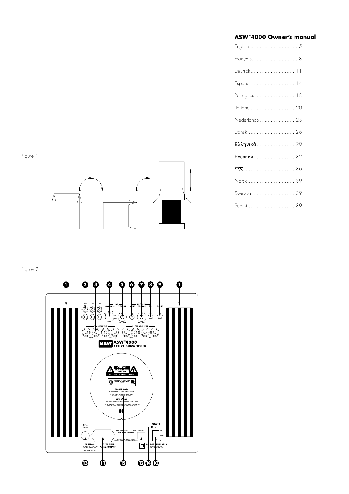
Figure 1
Figure 2
ASW™4000 Owner’s manual
English ...............................5
Français..............................8
Deutsch.............................11
Español ............................14
Português ..........................18
Italiano .............................20
Nederlands .......................23
Dansk...............................26
Ελληνικά .........................29
Русский...........................32
................................36
Norsk...............................39
Svenska ............................39
Suomi...............................39
TO SPEAKERS FROM AMPLIFIER
R
L
100
14040
80
70
50
60
MIN MAX MIN MAX
A B 0 180
PHASEEQ.
LINK
OUT
LINEINLINE
OUT
RIGHT
LEFT
RIGHT LEFT
B&W LOUDSPEAKERS LTD
WORTHING ENGLAND
CAUTION: SEE OPERATING MANUAL
ATTENTION: VOIR LE CAHIER D'INSTRUCTIONS
FOR CONTINUED PROTECTION
AGAINST FIRE HAZARD,
REPLACEWITH ONLY SAME
TYPE AND RATING FUSE.
CAUTION:
WHEN SERVICING, USE ONLY
IDENTICAL REPLACEMENT PARTS
DOUBLE INSULATEDATTENTION:
ACTIVE SUBWOOFER
POWER
ON
AUTO
OFF
FUSE
115V~T8A
230V~T4A
50/60Hz~
TO PREVENT FIRE OR SHOCK HAZARD DO NOT
EXPOSE THIS UNIT TO RAIN OR MOISTURE
NO USER SERVICEABLE PARTS INSIDE REFER
SERVICING TO QUALIFIED PERSONNEL
WARNINGS:
POUR EVITER TOUS RISQUES DE FEU OU DE CHOC ELECTRIQUE
N’EXPOSEZ PAS CET APPAREIL A L’HUMIDITE
AUCUN COMPOSANT NE PEUT ETRE REMPLACE PAR L’UTILISATEUR
VEUILLEZ CONTACTER LE SERVICE APRES VENTE AGREE
ATTENTION:
1 2 3 4 5 6 7 8 9 1
13 11 15 12 14 10
All manuals and user guides at all-guides.com
1
Figure 3
Figure 4
SUBWOOFER
SURROUND
CENTRE
L
R
FRONT
L
R
Decoder
No. 2
No. 1
Phono ‘T’ – splitter, used
to provide two connections
from single output
TO SPEAKERS FROM AMPLIFIER
R
L
100
14040
80
70
50
60
MIN MAX MIN MAX
A B 0 180
PHASEEQ.
LINK
OUT
LINEINLINE
OUT
RIGHT
LEFT
RIGHT LEFT
ACTIVE SUBWOOFER
TO SPEAKERS FROM AMPLIFIER
R
L
100
14040
80
70
50
60
MIN MAX MIN MAX
A B 0 180
PHASEEQ.
LINK
OUT
LINEINLINE
OUT
RIGHT
LEFT
RIGHT LEFT
ACTIVE SUBWOOFER
SURROUND
CENTRE
L
R
FRONT
L
R
L
R
LINE IN
L
R
SPEAKERS OUT
RIGHT
LEFT
++
+
-
-
-
Decoder
Power Amplifier
No. 2 No. 1
TO SPEAKERS FROM AMPLIFIER
R
L
100
14040
80
70
50
60
MIN MAX MIN MAX
A B 0 180
PHASEEQ.
LINK
OUT
LINEINLINE
OUT
RIGHT
LEFT
RIGHT LEFT
ACTIVE SUBWOOFER
TO SPEAKERS FROM AMPLIFIER
R
L
100
14040
80
70
50
60
MIN MAX MIN MAX
A B 0 180
PHASEEQ.
LINK
OUT
LINEINLINE
OUT
RIGHT
LEFT
RIGHT LEFT
ACTIVE SUBWOOFER
All manuals and user guides at all-guides.com
2
TO SPEAKERS FROM AMPLIFIER
R
L
100
14040
80
70
50
60
MIN MAX MIN MAX
A B 0 180
PHASEEQ.
LINK
OUT
LINEINLINE
OUT
RIGHT
LEFT
RIGHT LEFT
ACTIVE SUBWOOFER
RIGHT
LEFT
++
CENTRE
L
R
L
R
SURROUND
FRONT
+
+
+
-
-
--
-
Integrated Decoder
No. 2 No. 1
TO SPEAKERS FROM AMPLIFIER
R
L
100
14040
80
70
50
60
MIN MAX MIN MAX
A B 0 180
PHASEEQ.
LINK
OUT
LINEINLINE
OUT
RIGHT
LEFT
RIGHT LEFT
ACTIVE SUBWOOFER
Figure 5
Figure 6
SUBWOOFER
+
-
SURROUND
CENTRE
L
R
FRONT
+
-
+
-
+
-
L
R
Integrated Decoder
No. 2
No. 1
TO SPEAKERS FROM AMPLIFIER
R
L
100
14040
80
70
50
60
MIN MAX MIN MAX
A B 0 180
PHASEEQ.
LINK
OUT
LINEINLINE
OUT
RIGHT
LEFT
RIGHT LEFT
ACTIVE SUBWOOFER
TO SPEAKERS FROM AMPLIFIER
R
L
100
14040
80
70
50
60
MIN MAX MIN MAX
A B 0 180
PHASEEQ.
LINK
OUT
LINEINLINE
OUT
RIGHT
LEFT
RIGHT LEFT
ACTIVE SUBWOOFER
All manuals and user guides at all-guides.com

3
Figure 7
Figure 8
RIGHT
LEFT
++
L
R
LINE OUT
L
R
LINE IN
L
R
SPEAKERS OUT
+
TO SPEAKERS FROM AMPLIFIER
R
L
100
14040
80
70
50
60
LOW–PASS VOLUME
MIN MAX
POWER
ON
AUTO
OFF
PHASE
0 180
LINK
OUT
LINEINLINE
OUT
RIGHT
LEFT
RIGHT LEFT
ASW™4000
ACTIVE SUBWOOFER
TO SPEAKERS FROM AMPLIFIER
R
L
100
14040
80
70
50
60
LOW–PASS VOLUME
MIN MAX
POWER
ON
AUTO
OFF
PHASE
0 180
LINK
OUT
LINEINLINE
OUT
RIGHT
LEFT
RIGHT LEFT
ASW™4000
ACTIVE SUBWOOFER
-
-
-
Pre-Amplifier
Power Amplifier
No. 1
No. 2
RIGHT
LEFT
++
L
R
LINE OUT
L
R
LINE IN
L
R
SPEAKERS OUT
+
TO SPEAKERS FROM AMPLIFIER
R
L
100
14040
80
70
50
60
LOW–PASS VOLUME
MIN MAX
POWER
ON
AUTO
OFF
PHASE
0 180
LINK
OUT
LINEINLINE
OUT
RIGHT
LEFT
RIGHT LEFT
ASW™4000
ACTIVE SUBWOOFER
TO SPEAKERS FROM AMPLIFIER
R
L
100
14040
80
70
50
60
LOW–PASS VOLUME
MIN MAX
POWER
ON
AUTO
OFF
PHASE
0 180
LINK
OUT
LINEINLINE
OUT
RIGHT
LEFT
RIGHT LEFT
ASW™4000
ACTIVE SUBWOOFER
--
-
Pre-Amplifier
Power Amplifier
No. 1
No. 2
All manuals and user guides at all-guides.com

4
Figure 9
Figure 10
RIGHT
LEFT
++
L
R
SPEAKERS OUT
+
-
-
-
Integrated Amplifier
No. 2
No. 2
TO SPEAKERS FROM AMPLIFIER
R
L
100
14040
80
70
50
60
MIN MAX MIN MAX
A B 0 180
PHASEEQ.
LINK
OUT
LINEINLINE
OUT
RIGHT
LEFT
RIGHT LEFT
ACTIVE SUBWOOFER
TO SPEAKERS FROM AMPLIFIER
R
L
100
14040
80
70
50
60
MIN MAX MIN MAX
A B 0 180
PHASEEQ.
LINK
OUT
LINEINLINE
OUT
RIGHT
LEFT
RIGHT LEFT
ACTIVE SUBWOOFER
RIGHT
LEFT
++
L
R
SPEAKERS OUT
+
-
-
-
Integrated Amplifier
No. 2
No. 1
TO SPEAKERS FROM AMPLIFIER
R
L
100
14040
80
70
50
60
MIN MAX MIN MAX
A B 0 180
PHASEEQ.
LINK
OUT
LINEINLINE
OUT
RIGHT
LEFT
RIGHT LEFT
ACTIVE SUBWOOFER
TO SPEAKERS FROM AMPLIFIER
R
L
100
14040
80
70
50
60
MIN MAX MIN MAX
A B 0 180
PHASEEQ.
LINK
OUT
LINEINLINE
OUT
RIGHT
LEFT
RIGHT LEFT
ACTIVE SUBWOOFER
All manuals and user guides at all-guides.com
all-guides.com

5
Safety Instructions
Caution:
To reduce the risk of electric shock, do not
remove the back panel. No user-serviceable
parts inside. Refer servicing to qualified
personnel.
Explanation of Graphical Symbols
The lightning flash within an equilateral triangle
is intended to alert you to the presence of un-
insulated "dangerous voltage" within the product’s
enclosure that may be of sufficient magnitude to
constitute an electric shock to persons.
The exclamation point within an equilateral
triangle is intended to alert you to the presence
of important operating and maintenance
(servicing) instructions in the literature
accompanying the appliance
1 Read Instructions – All the safety and
operating instructions should be read before
the appliance is operated.
2 Retain Instructions – The safety and operating
instructions should be retained for future
reference.
3 Heed Warnings – All warnings on the
appliance and in the operating instructions
should be adhered to.
4 Follow Instructions – All operating and use
instructions should be followed.
5 Water and Moisture – The appliance should
not be used near water – for example, near
a bathtub, washbowl, kitchen sink, laundry
tub, in a wet basement, or near a swimming
pool and the like.
6 Carts and Stands – The appliance should be
used only with a cart or stand that is
recommended by the manufacturer.
7 Wall or Ceiling Mounting – The appliance
should be mounted to a wall or ceiling only
as recommended by the manufacturer.
8 Ventilation – The appliance should be
situated so that its location or position does
not interfere with its proper ventilation. For
example, the appliance should not be
situated on a bed, sofa, rug, or similar
surface that may block the ventilation
openings; or placed in a built-in installation,
such as a bookcase or cabinet, that may
impede the flow of air through the ventilation
openings.
9 Heat – The appliance should be situated
away from heat sources such as radiators,
heat registers, stoves, or other appliances
that produce heat.
10 Power Sources – The appliance should be
connected to a power supply only of the
type described in the operating instructions
or as marked on the appliance.
11 Grounding or Polarisation – The appliance
should not be grounded. When using an
extension power-supply cord or a power-
supply cord other than that supplied with the
appliance, it should be 2-core, fitted with the
appropriate moulded-on plugs and carry
safety approval appropriate to the country
of use.
12 Power Cord Protection – Power-supply cords
should be routed so that they are not likely
to be walked on or pinched by items placed
on or against them, paying particular
attention to cords at plugs, convenience
receptacles and the point where they exit
from the appliance.
13 Cleaning – The appliance should be
cleaned only as recommended by the
manufacturer.
14 Non-use Periods – The power cord of the
appliance should be unplugged from
the outlet when left unused for a long
period of time.
15 Object and Liquid Entry – Care should be
taken so that objects do not fall and liquids
are not spilled into the enclosure through
openings.
16 Damage Requiring Service – The appliance
should be serviced by qualified personnel
when:
a The power-supply cord or the plug has
been damaged; or
b Objects have fallen, or liquid has been
spilled into the appliance; or
c The appliance has been exposed to rain; or
d The appliance does not appear to operate
normally, or exhibits a marked change in
performance; or
e The appliance has been dropped, or the
enclosure damaged.
17 Servicing – The user should not attempt to
service the appliance beyond that described
in the operating instructions. All other
servicing should be referred to qualified
service personnel.
Warnings:
To prevent fire or shock hazard, do not expose
this equipment to rain or moisture.
Observe all warnings on the equipment itself.
To avoid electrical shock, do not open the
enclosure or remove the amplifier from the
rear panel. There are no user serviceable
parts inside. Refer all service questions to an
authorised B&W dealer.
To prevent electric shock, do not use this
(polarised) power plug with an extension cord
receptacle or other outlet unless the blades can
be fully inserted to prevent blade exposure.
Ensure that the voltage indicated on the amplifier
panel matches that of the power supply. If it
does not, contact an authorised B&W dealer to
alter the setting of the voltage selector.
The mains fuseholder is located on the back
panel of the amplifier module. Replacement fuse
must be of the same type and rating as supplied.
The equipment should not be earthed (grounded).
To ensure adequate cooling of the amplifier,
operate the equipment only with the heatsink fins
aligned vertically.
The subwoofer is heavy and bulky, it should
be moved or lifted by at least two people.
Check that there are no cables under the carpet
that may be damaged by the spikes.
Do not walk the unit on the spikes as this may
cause them to become detached from the
cabinet and cause damage.
Take care not to spike through your own feet.
GB
All manuals and user guides at all-guides.com

6
Introduction
Thank you for purchasing the B&W ASW™4000
Active Subwoofer.
Since its foundation in 1966, the continuing
philosophy of B&W has been the quest for
perfect sound reproduction. Inspired by the
company’s founder, the late John Bowers, this
quest has entailed not only high investment in
audio technology and innovation but also an
abiding appreciation of music and the demands
of film sound to ensure that the technology is put
to maximum effect.
The ASW™4000 has been designed for Home
Theatre installations and to augment the bass
performance of ‘full range’ speakers in stereo
audio use. Adding the subwoofer to your
system not only extends the bass to lower
frequencies, it improves the midrange clarity
by reducing the low-frequency demands on
your existing speakers.
The subwoofer is magnetically shielded for use
close to a television screen.
Please read through this manual fully before
using the subwoofer. All sound installations
require some planning and experimentation if
you are to get the best out of the products used
and this manual will guide you in this process.
As the subwoofer is connected to the electricity
power supply, it is important that you familiarise
yourself with the safety instructions and heed
all warnings.
Keep this manual in a safe place for future
reference.
B&W loudspeakers are distributed to over 60
countries world-wide and we maintain an
international network of carefully chosen and
dedicated distributors. If you have a problem
which your dealer cannot resolve, our distributors
will be more than willing to assist you.
Unpacking (figure 1)
The easiest way to unpack the subwoofer and
avoid damage is as follows:
• Open the carton flaps right back and invert
the carton and contents.
• Lift the carton away from the product.
• We recommend that you retain the packaging
for future use.
In addition to this manual, the carton
should contain:
• 1 Subwoofer
• 1 Accessory pack containing:
•
4 Spikes with lock nuts
•
4 Self-adhesive rubber feet
• 1 Phono ‘T’-splitter plug
A tour of the subwoofer (figure 2)
1 Heatsink
2 Line level connectors
3 Speaker level connectors
4 Low-pass filter frequency control (line input)
5 Volume control (line input)
6 Decoder input
7 Volume control (decoder input)
8 Equalisation switch (decoder input)
9 Phase switch
10 On/Auto/Off switch
11 Mains input socket
12 Voltage selector/indicator
13 Fuseholder
14 Power/Standby indicator
15 Toroidal mains transformer housing
Positioning the subwoofer
Because the subwoofer produces only low-
frequency sounds, positioning is less critical in
some respects compared with full-range speakers.
Directional information is much less precise and
you have more choice where to place the
speakers to good effect. This said, best results
are obtained if the subwoofer is placed between
the satellite speakers or in the vicinity of one of
them. If you use two subwoofers, it is best to put
one near each satellite speaker.
Placing the subwoofer behind the listeners, even
in surround sound installations, generally gives
inferior imaging; but may be an acceptable
compromise if domestic considerations dictate.
As with all speakers, the proximity of room
boundaries affects the sound. Bass is generally
increased as more surfaces come into close
proximity with the speakers. Unlike full-range
speakers, however, you can always restore the
correct overall system balance by adjusting the
volume level of the subwoofer. The more boost
you get from the room, the less hard the speaker
has to work; but there is a down side. Corner
positions often excite more low-frequency room
resonances, making the bass more uneven with
frequency. There is no substitute for experiment
as all rooms behave differently, so try the
subwoofer in a variety of positions before
making a final decision. A piece of music with
a bass line ascending or descending the musical
scale is useful for assessing the smoothness of
the bass response. Listen for exaggerated or
quiet notes. Having a separate subwoofer does
enable you to optimise for room resonances
independently from siting the satellite speakers
for best imaging.
If the subwoofer is to be used in a confined
space (eg in custom furniture), the space must
be ventilated to allow sufficient air to circulate
and cool the unit. Ask your dealer for advice.
The subwoofer is supplied with four spike feet.
The spikes pierce through carpet pile, giving a
firm support directly to the floor surface without
crushing the pile. When fitting spikes, first screw
the lock nuts fully onto the spikes, then screw
the spikes fully onto the threaded inserts in the
base of the cabinet. If the unit rocks, loosen the
relevant two opposing spikes until the support is
firm, then re-tighten the lock nuts to the inserts.
If the unit is to be placed on a vulnerable surface,
either place a protective disc under each spike
or fit the four rubber pads in place of the spikes.
Electrical connections
Disconnect all sound system equipment from the
power supply until the signal connections have
been made and checked. This avoids the risk of
damage whilst connections are made or broken.
The function of the subwoofer is to receive
signals from the amplification chain and, where
necessary split the signal into low bass and
higher frequencies and feed the latter back out
to the satellite speakers. Left and right channel
inputs may be combined into a single mono low
bass feed to the subwoofer drive unit if required.
The subwoofer will input and output both line
level signals via the RCA Phono sockets and
speaker level signals via the binding posts
located on the back panel, giving a flexible
choice of connection methods. However, you
must not use a mixture of line level and speaker
level connections in the same installation. If you
have a choice between line level and speaker
level connections, choose line level.
The subwoofer also has a dedicated decoder
input, which is automatically selected if a signal
is present on this input. If no signal is detected
on this input for approximately 20 seconds, the
subwoofer will switch to the line/speaker level
inputs.
Decoder volume and equalisation are set by
separate controls from the line and speaker
inputs, for ease of installation.
Use the following table to select the correct
wiring method for your installation:
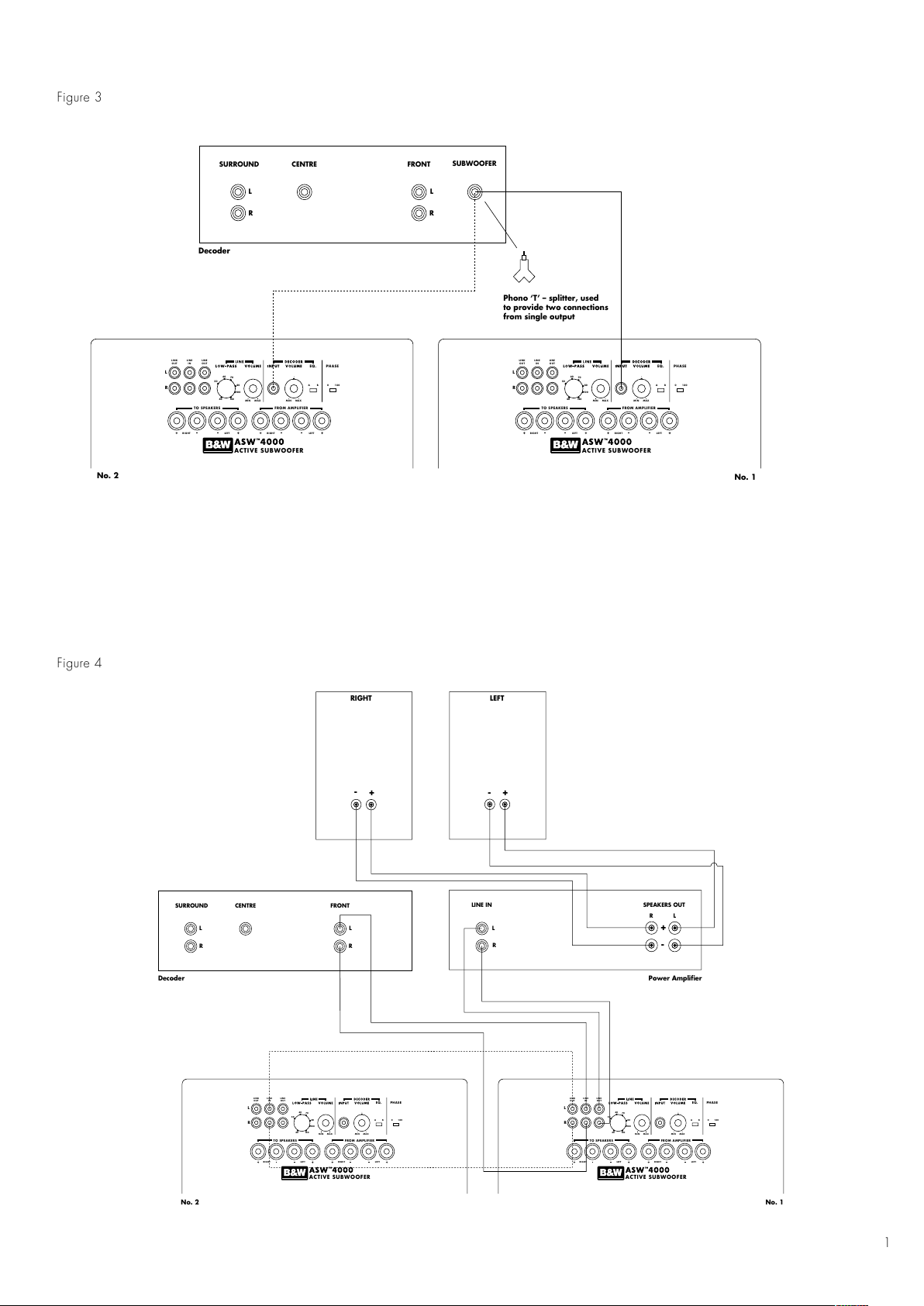
Application: Home Theatre
• Decoder with separate power amplifiers:
a With subwoofer output: Connections: fig. 3
b No subwoofer output: Connections: fig. 4
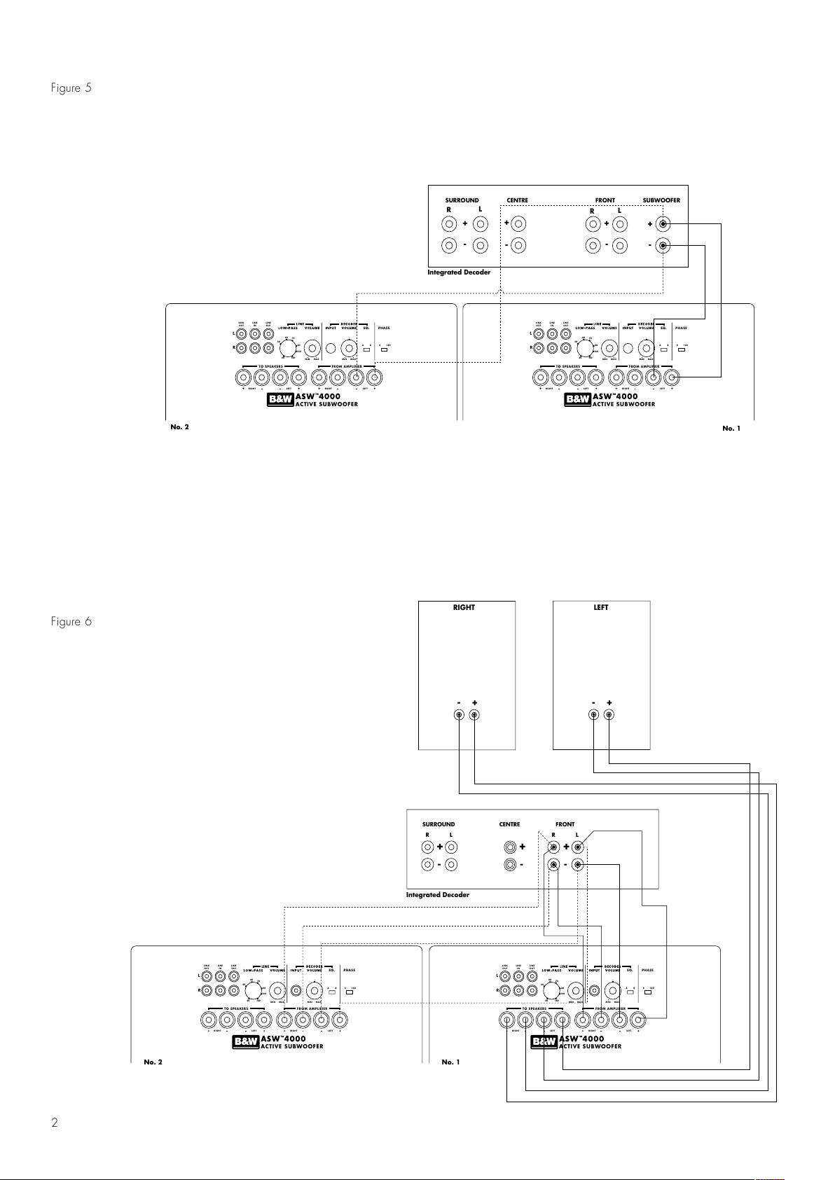
• Decoder with integrated power amplifiers:
a With subwoofer output: Connections: fig. 5
b No subwoofer output: Connections: fig. 6
Application: Stereo Audio
Separate pre- & power amplifiers:
a One or more subwoofers with output
combined into a single mono signal:
Connections: fig. 7
b Two subwoofers with separate left and right
signals: Connections: fig. 8
• Integrated amplifier:
a One or more subwoofers with output
combined into a single mono signal:
Connections: fig. 9
b Two subwoofers with separate left and
right signals: Connections: fig. 10
Using more than one subwoofer
Using more than one unit in a single installation
can improve performance in the following ways:
All manuals and user guides at all-guides.com

7
• Maintain stereo separation to the lowest
frequencies.
• Cope with larger listening rooms.
• Enable greater maximum sound output – often
useful for effectively reproducing special effects
in Home Theatre applications.
• Smooth out the effects of low-frequency room
resonances.
If you are using two subwoofers for stereo audio,
stereo separation is improved if each channel
has its own subwoofer, providing each one is
sited close to the relevant satellite speaker.
If using a decoder, use the phono ‘T’-piece
provided, and make connections to the decoder
input on each subwoofer. For two channel audio,
use both line input channels.
Double check the connections
ENSURE THAT THE VOLTAGE INDICATED
ON THE AMPLIFIER PANEL MATCHES THAT
OF THE POWER SUPPLY.
Before auditioning the sound quality of your new
installation and fine tuning it, double check the
connections. All too often, users complain that
they cannot get a decent sound however they set
the controls, only to discover something has been
wrongly connected. Make sure that:
•
The phasing is correct – there should be no
positive to negative connections (this applies
only to speaker level interconnects). If
something is out of phase you may get a fuzzy
sound with an imprecise and floating image,
a lack of bass or a combination of the two.
• There are no left to right mix-ups – this can
result, for example, in the orchestra being the
wrong way round or, more disastrously, sounds
on your Home Theatre going in the opposite
direction to the action on the screen.
Switching on and off
We recommend that you switch the subwoofer
on before any power amplifiers receiving signals
from the subwoofer. Similarly, when switching
off, switch the subwoofer off last.
Auto:
On first switching the subwoofer to Auto, the
amplifier becomes fully active and the light
above the on/auto/off switch glows green.
After a period of about 5 minutes without an
input signal, the amplifier automatically reverts to
standby mode, and the light glows red. When
an input signal is detected, the amplifier
automatically becomes fully active and the light
glows green.
On:
With the switch in this position, the amplifier
remains permanently on, and the light glows
green.
Off:
In this position, the amplifier is in standby, and
the light glows red.
Setting the controls
Line and speaker level inputs
There are three controls to consider:
• The LOW-PASS filter frequency
• The VOLUME control
• The PHASE switch
Decoder input
There are three controls to consider:
• The DECODER VOLUME control
• The PHASE switch
• The EQUALISATION switch
The optimum settings depend on the other
equipment used with the subwoofer. If using
more than one subwoofer, make sure the controls
on each one are set the same.
Use with THX®controllers (including THX
controllers set in non-THX mode)
The ASW™4000 is not a THX®licensed
component, but may be used with a THX
®
controller if desired.
• Set the decoder volume control to the detent at
the half-way (12 o’clock) position (this is a
standard THX®pre-set level of 88dB SPL @ 1m
for 100mV input signal).
• Set the EQUALISATION switch initially to
position A, then see the section below on
fine tuning.
• Set the PHASE switch initially to 0°, then see
the section below on fine tuning.
Ensure that the subwoofer function on the THX
®
controller is enabled. When so configured it
incorporates all the filtering and level setting
required for the subwoofer in all modes. For level
calibration, the internal test noise and channel
level controls in the THX®controller should be
used. In all cases the levels should be set so as
to obtain 75dB spl (C-weighted) at the listening
position from the controller’s internal noise test
signal. Refer to your controller manual for further
details as to how to set the levels. Inexpensive
sound level meters are readily available from
electronics stores and should be used to
calibrate the levels.
Use with other Home Theatre decoders
• If the decoder has a dedicated subwoofer
output and an internal LOW-PASS filter for the
subwoofer having a slope of 2nd-order
(12db/octave) or greater, set the LOW-PASS
filter frequency to maximum, otherwise set it
initially to 80 Hz.
•
Set the VOLUME control initially to the half-way
(12 o’clock) position, then see the section
below on fine tuning.
• Set the PHASE switch initially to 0°, then see
the section below on fine tuning.
Use for stereo audio
•
Set the LOW-PASS filter initially to 80 Hz then
see the section below on fine tuning.
• Set the volume control initially to the half way
(12 o’clock) position, then see the section
below on fine tuning.
•
Set the PHASE switch initially to 0°, then
see the section below on fine tuning.
Fine tuning
The setting of the EQUALISATION switch affects
only the signal via the decoder input. Position A
is optimised to allow the subwoofer to provide
the highest listening levels, while position B gives
greater bass extension.
The optimum settings of the PHASE switch and
the LOW-PASS filter frequency are inter-related
and also dependent on the low-frequency
cut-off characteristic of the satellite speakers
and the relative positions of all the speakers
in the installation.
Set the system up in the preferred position and
play some programme with a steady basscontent.
The optimum setting for the LOW-PASS cut-off
frequency depends on several variables – the
bass performance and power handling of the
satellite speakers, the number of subwoofers
used and their position relative to the satellite
speakers. The range 80-90 Hz is a good
starting point for the LOW-PASS frequency.
Unless two subwoofers are used to preserve
separate right and left channel information and
are sited close to the relevant satellite speakers,
using a higher cut-off frequency may compromise
the stereo image and should only be considered
if the bass performance of the satellite speakers
is particularly limited.
At each setting of the cut-off frequency, listen with
the phase switch in both positions. The correct
one is that which gives the fullest bass and that
will depend on the bass characteristics of your
satellite speakers and the relative distances of
the subwoofer(s) and the satellite speakers to the
listeners. When using more than one subwoofer,
ensure that each one has its cut-off frequency
and phase switch set the same way.
If at any time you make changes to the
amplification of the system such that you change
from speaker to line level connections to the
subwoofer, it is worth checking the phase setting
again, as the speaker level and line level
high-pass filter phase characteristics of the
subwoofer are different.
Set the loudness of the subwoofer relative to the
satellite systems to your liking. Use a wide
variety of programme material to get an average
setting. One that sounds impressive on one piece
may sound overpowering on another. Listen at
realistic levels as the perception of balance
varies with sound level.
If you get problems with lumpy bass – if certain
bass notes are exaggerated more than others –
then you probably have a room interface
problem and it is worth experimenting with the
placement of the subwoofer. What may seem
like small changes in position – 15cm (6in) or
so – can have a profound effect on the sound.
All manuals and user guides at all-guides.com

8
F
Try raising the subwoofer clear of the floor as
well as lateral movement. The use of multiple
subwoofers can smooth the effects of room
resonances as each subwoofer will tend to excite
resonances at different frequencies. If you alter
the relative distances from the subwoofer(s)
and satellite speakers to the listeners
appreciably, reassess the phase switch setting.
You should also check the level setting of the
subwoofer (using either the decoder output
levels or the volume control on the subwoofer
amplifier as appropriate), but only after setting
the phase correctly.
Taking care of the subwoofer
The cabinet of the subwoofer may be cleaned
by dusting with a dry cloth. If you wish to use
an aerosol cleaning spray, do not spray directly
on the cabinet; spray onto the cloth. Remove
the grille first so that the cloth does not become
stained, but be careful not to disturb the drive
unit. The grille itself may be cleaned using
a soft brush.
Do not use the subwoofer as a table. When
in use, objects left on top of the subwoofer are
liable to rattle. In particular, avoid the risk of
liquids being spilled (eg from drinks or vases
of flowers).
If the system is taken out of use for a long period,
disconnect the subwoofer from the power supply.
Avertissements:
Pour éviter tout risque d’incendie ou
d’électrocution, n'exposez jamais cet appareil à
la pluie ou même a l'humidité.
Assurez-vous, en premier lieu, que la tension
indiquée sur l'appareil correspond bien a celle
de votre réseau électrique. Si vous ne pouvez le
faire, contactez un revendeur B&W autorisé. Ne
tentez pas de modifier le réglage du sélecteur
de tension.
Observez tout signe anormal pouvant provenir
du subwoofer lui-même, n'ouvrez jamais
l'enceinte et ne sortez pas l'amplificateur de son
logement; vous n’y trouverez aucun réglage utile.
En cas de problème renseignez-vous,
préalablement à toute intervention, auprès
d'un véritable revendeur spécialiste de la
marque B&W.
Pensez que vous risquez l'électrocution si vous
n'enfoncez pas complètement les pôles de
la prise d’alimentation, surtout lorsque
vous employez un prolongateur ou un
raccord électrique.
Les fusibles d'alimentation se trouvent sur le
panneau du module d'amplification. En cas
de remplacement, n'utilisez jamais de fusibles
d’un type différent; vérifiez que les valeurs
indiquées sur les nouveaux fusibles sont
parfaitement identiques à celles qui figurent sur
les modèles d'origine.
Cet appareil ne doit pas être raccordé à
la terre.
Pour assurer une ventilation suffisante à
l'amplificateur, les ailettes des radiateurs de
refroidissement doivent être orientées en
position verticale.
Ce subwoofer est lourd et volumineux, il doit être
manipulé par un minimum de deux personnes.
Contrôlez que les câbles ne risquent pas d'être
transpercés par les pointes de découplage.
Ne déplacez pas l'appareil en le faisant glisser
sur ses pointes. Vous risquez de les arracher ou
de créer des dégats.
Prenez simplement garde de ne pas vous piquer.
Introduction:
Nous vous remercions d'avoir choisi le
Subwoofer actif B&W ASW™4000.
Depuis la création de notre entreprise en 1966,
la base invariable de notre philosophie a toujours
été la recherche de la perfection absolue.
Inspirée par son fondateur, le regretté John
Bowers, cette extraordinaire aventure qu’est la
quête de l'absolu, n'a pas seulement débouché
sur de très lourds investissements consacrés à la
recherche et à l'innovation, mais aussi sur une
profonde connaissance de la musique et des
spécificités du son cinématographique. Cette
connaissance nous permet de nous assurer que
la technologie sera toujours utilisée au service
du meilleur résultat possible et non à la
technique pour la technique.
L'ASW™4000 n’a pas seulement été étudié
pour les installations de Home Cinéma, il
conviendra naturellement à la reproduction de
haute qualité des très basses fréquences de toute
chaîne sonore.
Ce subwoofer apporte, en plus d’une extension
spectaculaire de la réponse vers l'extrème-grave,
une amélioration non négligeable de la clarté
de reproduction du médium, grâce à la réduction
du travail demandé aux enceintes principales.
L’ASW
™
4000 est blindé magnétiquement.
Vous pouvez donc l'utiliser à proximité de
votre téléviseur.
Veuillez lire attentivement et totalement cette
notice avant d'utiliser votre subwoofer. Toute
installation sonore recquiert un minimum
d'attention et d'expérimentation quand on
souhaite en tirer le meilleur parti; ce manuel
vous guidera dans cette voie.
Avant de raccorder le subwoofer au réseau
électrique, il est important que vous ayez pris
connaissance des consignes de sécurité pour
que vous puissiez tenir compte de tout signe
anormal ou alarmant.
Rangez ce guide de telle façon que vous
puissiez le retrouver facilement pour de
futures consultations.
La distribution de B&W est assurée dans plus de
60 pays à travers le monde. Nous entretenons
un réseau d’importateurs sélectionnés avec la
plus grande attention.
Quelque soit le problème qu'un revendeur ne
saurait régler, n'hésitez jamais à contacter votre
agent national afin qu'il puisse vous assister.
Deballage: (figure 1)
Pour déballer aisément votre subwoofer tout en
évitant le risque d’un choc malencontreux,
veuillez procéder de la manière suivante:
Ouvrez les abattants du carton au maximum puis
retournez le colis.
Il suffit ensuite de soulever le carton pour que
l'appareil sorte de l'emballage.
Nous vous conseillons de conserver le carton et
ses accessoires pour toute utilisation ultérieure.
En plus de ce manuel vous trouverez également:
• Le Subwoofer
• Un sachet d’accessoires contenant:
• 4 pointes de découplage
• 4 tampons auto-adhésifs
• 1 raccord de dédoublement CINCH en T
All manuals and user guides at all-guides.com

40
Description
Drive units
System frequency response
Low-Pass Filter
High-Pass Filter
Internal Volume
Dimensions
Net Weight
Finish
ASW™4000
THX is a registered trademark of Lucasfilm Ltd. B&W Loudspeakers Ltd.
reserves the right to amend details of the specification without notice in line with technical developments.
Copyright © B&W Loudspeakers Ltd. Printed in England.
B&W Loudspeakers Ltd, Meadow Road, Worthing, BN11 2RX Tel: +44 (0) 1903 524801 Fax: +44 (0) 1903 524725
http://www.bwspeakers.com
Active vented-box subwoofer
One 380mm (15 in) dia long throw with magnetic shielding
±3dB 17Hz - 40 / 140Hz adjustable (Line In)
±3dB 17Hz - 250Hz (Decoder In, EQ at ‘B’)
±3dB 24Hz - 250Hz (Decoder In, EQ at ‘A’)
Amplifier Power output 450W continuous
Input impedance 22kW
Sensitivity 88dB spl at 1m for 100mV input
(Decoder input, level set to centre detent position)
Signal/Noise 90dB
Functions Line input level
Decoder input level
Decoder input equalisation
Phase 0/180
Inputs Line In (RCA Phono)
Decoder In (RCA Phono)
Speaker Level In (Binding Posts)
Outputs Line Out (RCA Phono, h-p filtered)
Link Out (RCA Phono)
Speaker Level Out (Binding Posts, h-p filtered)
Active 4th-order variable cut-off 40Hz - 140Hz (Line In)
fixed cut-off 250Hz
Line Level active 3rd-order at 80Hz
Speaker Level passive 1st-order at 80Hz into 8W resistor
(Response using speaker level connections
dependent on satellite impedance)
100 litres (3.6 cu ft)
Height: 580mm (22.8 in)
Width: 610mm (24 in)
Depth: 580mm (22.8 in))
75kg (165 lb)
Cabinet: Real wood veneers of Black Ash,
Cherrywood and Red Stained Cherrywood
Grille: Black cloth
I4840
All manuals and user guides at all-guides.com
all-guides.com
 Loading...