

Page 1

Analogue Internal Micrometer
Operating Instructions
Micromètres d’intérieur
Notice d’Utilisation
Mechanische
Innenmessschrauben
Bedienungsanleitung
Istruzioni d’uso Micrometri per
Interni Analogici Serie
Micrometros de Interiores
Analogicos Bowers A
Manual de instrucciones
Page 2

NOMENCLATURE & SETTING INSTRUCTIONS (METRIC)
HOW TO READ...
All metric micrometers are graduated in 0.005mm divisions. The
sleeve has a datum line, and the thimble is graduated as illustrated
below. The sleeve is graduated in 0.5mm divisions and one complete
revolution of the thimble is equal to 0.5mm. To read the instrument,
read the size on the sleeve to obtain the nearest half millimetre and
to obtain hundredths and microns read the number on the thimble
which lines up with the datum line on the sleeve.
An example is illustrated below.
RESETTING PROCEDURE...
Should the gauge start to lose accuracy due to wear etc., it may be
reset as follows :-
1) Insert the instrument into the setting ring gauge and set at the
correct tightness using the ratchet controller.
2) Lock the spindle with the locking screw located through the
hole in the grip-ring.
3) Loosen the ratchet controller by inserting the allen-key provided
into the screw located in the end of the controller and unlock
the screw.
4) The thimble will now be free and can be rotated and set to the
size on the setting ring.
5) Re-tighten the controller screw and slacken off the spindle
locking screw. The micrometer is now reset.
6) Recheck the gauge in the setting ring. Gauge reading should be
the same as the setting ring calibrated value.
A KEY IS PROVIDED TO MAKE ADJUSTMENTS OF THE MICROMETER
NUT IN THE EVENT OF WEAR.
PROCEDURE:–
1) Remove the thimble and spindle assembly from the micrometer
by completely winding the thimble off the sleeve.
2) Locate the key in the slots of the brass nut.
3) Make adjustments in very small increments. A clockwise rotation
of the brass nut will close the nut to compensate for wear.
4) Replace the thimble assembly and recalibrate the gauge as per
resetting procedure above.
In the illustration above the micrometer reading would be
16.015mm.
EXTENSIONS: When extensions are used for deep hole
measurement it will be necessary to reset the instrument as per the
resetting instructions below.
IMPORTANT NOTE : The anvils have a fixed amount of travel. DO
NOT remove anvils from the measuring head.
Page 3
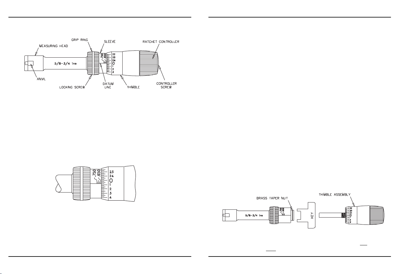
NOMENCLATURE & SETTING INSTRUCTIONS (Inch)
HOW TO READ...
All inch micrometers are graduated in 0.00025” divisions. The sleeve
has a datum line, and the thimble is graduated as illustrated below.
The sleeve is graduated in 0.025” divisions and one complete
revolution of the thimble is equal to 0.025”. To read the instrument,
read the size on the sleeve to obtain the tenths and hundredths and
to obtain thous and tenths of thous read the number on the
thimble which lines up with the datum line on the sleeve.
An example is illustrated below.
RESETTING PROCEDURE...
Should the gauge start to lose accuracy due to wear etc., it may be
reset as follows :-
1) Insert the instrument into the setting ring gauge and set at the
correct tightness using the ratchet controller.
2) Lock the spindle with the locking screw located through the
hole in the grip-ring.
3) Loosen the ratchet controller by inserting the allen-key provided
into the screw located in the end of the controller and unlock
the screw.
4) The thimble will now be free and can be rotated and set to the
size on the setting ring.
5) Re-tighten the controller screw and slacken off the spindle
locking screw. The micrometer is now reset.
6) Recheck the gauge in the setting ring. Gauge reading should be
the same as the setting ring calibrated value.
A KEY IS PROVIDED TO MAKE ADJUSTMENTS OF THE MICROMETER
NUT IN THE EVENT OF WEAR.
PROCEDURE:–
1) Remove the thimble and spindle assembly from the micrometer
by completely winding the thimble off the sleeve.
2) Locate the key in the slots of the brass nut.
3) Make adjustments in very small increments. A clockwise rotation
of the brass nut will close the nut to compensate for wear.
4) Replace the thimble assembly and recalibrate the gauge as per
resetting procedure above.
In the illustration above the micrometer reading would be 0.62575”
EXTENSIONS: When extensions are used for deep hole
measurement it will be necessary to reset the instrument as per the
resetting instructions below.
IMPORTANT NOTE : The anvils have a fixed amount of travel. DO
NOT remove anvils from the measuring head.
Page 4
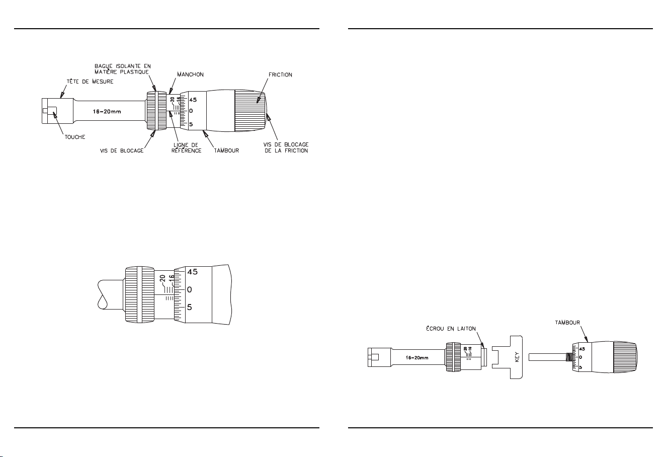
NOMENCLATURE ET NOTICE D’UTILISATION
POUR MICROMETRES D’INTÉRIEUR
LECTURE...
Tous les micromètres en unité métrique ont une résolution de
0.005mm. Un tour du tambour correspond à 0.5 mm. La lecture des
centièmes et demi-centièmes s’effectue sur le tambour à l’aide de la
ligne de référence placée sur le corps. La lectures des millimètres et
demi-millimètres s’effectue sur le corps. Voir dessin ci-dessous.
ETALONNAGE
1) Insérer le micromètre dans la bague étalon jusqu’a ce que le
micromètre soit immobilisé dans la bague..
2) Serrer avec la clé hexagonale la vis située au niveau de la bague
isolante en plastique.
3) Deserrer d’un tour avec cette même clé la vis située au centre de
la friction.
4) Le tambour peut être tourné pour la remise à la valeur indiquée
sur la bague étalon.
5) Rebloquer la vis de la friction.
6) Desserrer la vis située au niveau de la bague isolante en
plastique.
7) Le micromètre est maintenant réétalonné.
8) Vérifier l’étalonnage du micromètre dans la bague étalon.
UNE CLÉ SPÉCIALE EST PRÉVUE POUR PERMETTRE DE RATTRAPER
LE JEU DE LA VIS MICROMÉTRIQUE (consécutif à une longue
utilisation):
1) Enlever complètement le tambour
2) Introduire la clé spéciale dans les rainures de l’écrou en laiton.
3) Serrer légèrement et vérifier que le micromètre n’a plus de jeu.
Renouveler l’opération jusqu’à ce que le jeu de la vis
micrométrique soit rattrapé.
4) Remonter le tambour et réétalloner le micromètre.
Sur le dessin la lecture est: 16.015mm
RALLONGE: Il est important de reétalonner le micromètre lorsque
l’on utilise une ou plusieurs rallonges pour la mesure de trous de
grande profondeur.
IMPORTANT : Les têtes de mesure sont équippées avec des touches
fixes. Ne pas démonter les touches
Page 5
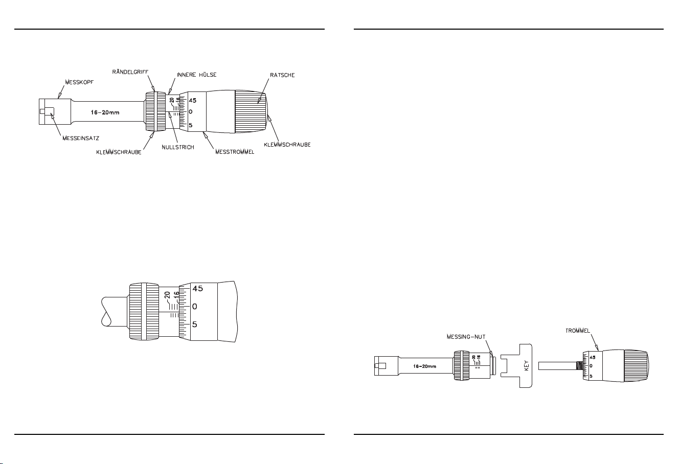
BEDIENUNGSANLEITUNG ZUR MECHANISCHEN INNENMEßSCHRAUBE
Alle Innenmeßschrauben haben einen Skalenwert von 0.005 mm. Die
innere Hülse ist mit einem waagerechten Nullstrich sowie mit den
0.5mm Teilstrichen und die Messtrommel mit den Teilstrichen der
Feinteilung, wie unten angezeigt¸ beschriftet. Eine Umdrehung der
Messtrommel entspricht einer Messbereichsänderung von 0.5 mm.
Ablesung der Messwerte
Der waagerechte Nullstrich (0.5 mm) kommt zur Deckung mit einem
Teilstrich der Feinteilung der Messtrommel: siehe nachstehendes
Beispiel:
NEUEINSTELLUNG
Sollte die Ablesung aufgrund häufigen Gebrauchs etc. ungenau
werden, kann diese wie folgt neu eingestellt werden :
1) Innenmessschraube in den Einstellring stellen und mit der
Ratsche einige Rasten durchdrehen.
2) Spindel anhand der Innensechskantschraube durch festziehen
der Feststellschraube im gerändelten Kunststoffring klemmen.
3) Ratsche durch lösen der stirnseitigen Innensechskantschraube
lockern.
4) Die Messtrommel wird hierdurch gelöst und die
Innenmessschraube kann auf das Maß des Einstellringes
eingestellt werden.
5) Schraube an der Ratsche festdrehen, Feststellschraube der
Spindel lösen.
6) Einstellung im Einstellring prüfen.
SOLLTE DURCH HÄUFIGEN GEBRAUCH DIE
MESSSCHRAUBENSPINDEL SPIEL AUFZEIGEN, KANN DIES MIT DEM
MITGELIEFERTEN SPEZIALSCHLÜSSEL
NACHGESTELLT WERDEN:–
1) Messtrommel mit Spindel komplett herausschrauben.
2) Spezialschlüssel in die Messing-Nut stecken.
3) Im Uhrzeigersinn vorsichtig drehen (geschlitzte Gewindemutter
wird geklemmt).
4) Spindel mit Messtrommel wieder einsetzen, eine Neueinstellung
durchführen (wie oben beschrieben).
In diesem Beispiel beträgt der Messwert 16.015 mm
VERLÄNGERUNGEN: Wenn Verlängerungen zur Messung von tiefen
Bohrungen eingesetzt werden, muß eine Neueinstellung (wie unten
beschrieben) durchgeführt werden.
WICHTIG: Die Messköpfe sind mit fixen Messeinsätzen ausgestattet,
d.h. die Messeinsätze sind NICHT wechselbar.
Page 6
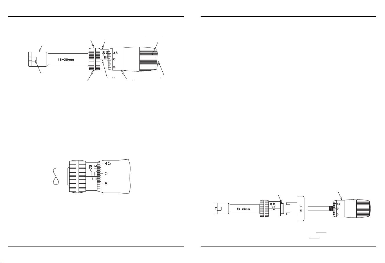
NOMENCLATURA E ISTRUZIONI DI TARATURA (micrometri metrici)
IMPUGNATURA
TESTA DI MISURA
INCUDINE
BLOCCAGGIO
COME LEGGERE….
Tutti i micrometri metrici hanno una divisione del nonio in 0.005
mm.
Il corpo fisso ha una linea di riferimento, ed il tamburo è graduato
come indicato nell’illustrazione seguente.
La linea fissa ha graduazioni di 0.5 mm, quindi un giro completo del
tamburo corrisponde a 0.5 mm. La lettura del micrometro viene
fatta in questo modo: i millimetri ed i decimi vengono letti sulla
graduazione della linea fissa, mentre i centesimi ed i micron si
leggono sul tamburo
NONIO
LINEA DI
RIFERIMENTO
CRICCHETTO
TAMBUROVITE DI
VITE DI BLOCCAGIO
TAMBURO
TARATURA DEL MICROMETRO….
In ogni caso si renda necessario, potere tarare nuovamente lo
strumento in questo modo:-
1) Inserire il micrometro all’interno dell’anello di taratura e portare a
contatto le incudini agendo sul cricchetto.
2) Bloccare l’asta interna del micrometro chiudendo il grano posto sul
lato del corpo strumento.
3) Allentare solamente di poco la vite esagonale posta al centro del
cricchetto con l’apposita chiave a brugola.
4) Il nonio è ora libero di ruotare ed essere portato al valore
corrispondente dell’anello.
5) Serrate ora nuovamente la vite in testa e liberate l’asta interna
riallentando il grano laterale. Il micrometro è tarato.
6) Ricontrollate lo strumento eseguendo una nuova misura nell’anello
di taratura, la misura dovrebbe corrispondere.
VIENE FORNITA IN DOTAZIONE ANCHE UNA CHIAVE SPECIALE PER
REGISTRARE LA MADREVITE INTERNA IN CASO DI USURA.
PROCEDURA:-
1) Svitare completamente il tamburo dal corpo del micrometro ed
estrarlo.
2) Posizionate la chiave speciale negli inserti della vite in ottone.
3) Eseguire la registrazione con rotazioni minime. Ruotando in senso
orario la vite in ottone tenderà a chiudersi, recuperando eventuali
giochi.
4) Rimontare il tamburo sul corpo strumento ed eseguire una nuova
taratura come descritto precedentemente.
VITE IN BRONZO DI TARATURA FINE
GRUPPO TAMBURO
L’illustrazione mostra come esempio una misura di 16.015 mm.
USO DI PROLUNGHE: quando si rende necessario l’utilizzo di
prolunghe per misure in fori profondi, è necessario tarare
nuovamente lo strumento come descritto in seguito:
NOTA IMPORTANTE: L’escursione delle incudini NON
modificata. Le incudini NON
possono essere rimosse
dalla testa.
può essere
Page 7
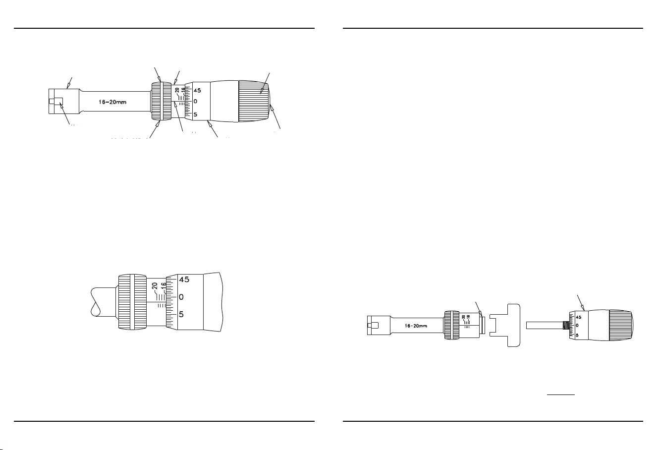
NOMENCLATURA E INSTRUCCIONES DE AJUSTE
EMBRAGUE
FRICCION
TORNILLO
FIJACION
CABEZA DE MEDICION
PALPADOR
TORNILLO
ANILLO
CENTRAL
NONIO
LINEA DE
REFERENCIA
TAMBOR
LLEECCTTUURRAA......
Todos los micrómetros métricos están graduados en divisiones de
0,005 mm. El husillo tiene una línea de referencia y el tambor está
graduado como muestra la siguiente figura. El husillo está graduado
en divisiones de 0,5 mm y una vuelta completa del tambor equivale
a 0,5 mm. Para realizar la lectura, lea el número del husillo para
obtener el medio milímetro más próximo y para centésimas y micras
lea el dígito del tambor que coincida con la línea de referencia del
husillo.
Un ejemplo:
PUESTA A CERO...
Si el micrómetro comienza a perder precisión debido al desgaste,
etc ajústelo como sigue:-
1) Introduzca el micrómetro en el anillo patrón adecuado y realice
una medición usando el embrague de fricción.
2) Bloquee el eje con el tornillo situado en el anillo central.
3) Afloje el embrague de fricción insertando la llave allen
suministrada en el tornillo de la parte trasera del embrague.
4) Ahora el tambor gira libre y puede posicionarlo correctamente
en la dimensión exacta del anillo patrón.
5) Vuelva a apretar el tornillo del embrague de fricción. El
micrómetro ya está ajustado.
6) Vuelva a comprobar la dimensión del anillo.
UNA LLAVE ESPECIAL SE SUMINISTRA PARA PERMITIR REAJUSTAR
EL JUEGO DEL HUSILLO
1) Retirar el tambor completamente.
2) Introduzca la llave especial en las ranuras de la tuerca de latón.
3) Apriete suavemente en pequeños incrementos. Repita la
operación hasta que el juego del husillo desaparezca..
4) Vuelva a montar el tambor y a calibrar el micrómetro.
En la figura la lectura del micrómetro es 16,015 mm.
ALARGADERAS: Cuando se empleen alargaderas para medición de
agujeros más profundos, es necesario poner a cero el instrumento
como indican las siguientes instrucciones.
TUERCA DE LATON
LLAVE
TAMBOR
NOTA IMPORTANTE: Los micrómetros de interiores BOWERS de la serie
XTA llevan palpadores fijos. NUNCA
intente
retirarlos ya que invalidaría el certificado y las
mediciones serían erróneas.
Page 8

Page 9

Bowers Metrology Ltd, 32 Leeds Old Road, Bradford, West Yorkshire, England, BD3 8HU
Sales, spares and repairs, please contact:
Tel: (0044) 01274 223456 Fax: (0044) 01274 223444
e-mail: [email protected] www.bowersmetrology.com
INS: 55-26-1
 Loading...