

Page 1
TEST INDICATOR INSTRUCTIONS
Test Indicator 420
and 421 Series
Please carefully review these instructions to ensure proper and accurate
use of your new Test Indicator.
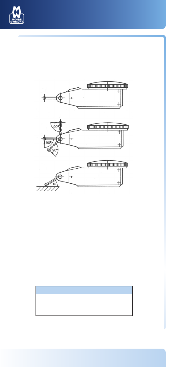
fig. 1
fig. 2
fig. 3
Mounting of Mounting Shaft
Slide mounting shaft onto dovetail which is best suited for measuring and
tighten (fig. 1). Mount indicator rigidly and as close as possible.
Measuring
For accurate measurements the axis of the contact point must be
perpendicular to the measuring direction (fig. 2). If this is not possible, it is
necessary to multiply the reading on the dial with a correction factor, which
depends on angle ∂ (fig. 3). The correction factor is negligible for angles
below 15º.
Angle ∂: 15º 30º 45º 60º
Correction factor: 0.96 0.87 0.70 0.50
Example
Angle ∂ : 30º (estimated)
Reading on dial: .015"
Measurement value: .015" x .87 = .013"
Maintenance
No special maintenance is required. The bearings of the indicator must not
be oiled.
visit www.moore-and-wright.com Partners in Precision
 Loading...