


R & Pro
 R & Pro
Owner’s Handbook
BWL0510/3 | Gemini R and Pro |
12/2010 |

contents |
|
warranty |
|
|
|
Information
Warranty |
2 |
CE Mark |
2 |
Safety Notes |
3 |
Operation
Controls |
4 |
Set-up |
5 |
Flash Power Control |
6 |
Ready Indications |
7 |
Modelling Control |
8 |
Photocell |
8 |
Triggering Options |
9 |
Changing the Flash Tube |
10 |
Error Indications |
11 |
Trouble Shooting |
11 |
Accessories |
|
Travelpak battery system |
12 |
Pulsar Radio Trigger System |
13 |
Light Modifiers |
13-14 |
Specifications |
14-15 |
All Bowens electrical products are covered by a two year warranty against any faulty design, materials and workmanship.
If a product does not work on arrival or up to a maximum period of four weeks from the date of purchase, it should be returned to the dealer/retail outlet from where it was purchased, to exchange (if available) the faulty unit for a new one; if the faulty unit was part of a kit that was purchased, the dealer / retailer may choose to simply replace the unit and not the entire kit. Alternatively the dealer may offer to repair the unit as soon as possible at no charge.
If neither an exchange or repair is possible for the faulty unit, then a full refund may be made.
If a warranty fault occurs after the initial four week period (and within the max two year warranty period), then the unit should be returned to the dealer, who will arrange to repair the unit as soon as possible, at no charge.
This warranty does not apply to consumable items such as flash tubes, modelling lamps, fuses, consumable type batteries.
Should a unit be returned at any time within the two year warranty period, and it is judged to have experienced any of the following points, failure to follow working instructions correctly, accidental or willful damage, misuse, alteration or repair by a non authorised Bowens service / repair centre, then the warranty will be deemed invalid and any repairs that may need carrying out will be payable by the owner.
The cost of any repairs should be notified to the owner, by the dealer, in advance of undertaking any work that may be required.
No warranty repairs can be undertaken to any units without proof of purchase.
All warranty repairs or returns must be conducted with the dealer from where the product was purchased.
Other terms and conditions may be applicable in specific countries, if stated by the dealer at the time of purchase.
All Bowens products are certified by the CE mark. The CE certified mark is a declaration of conformity to the required EEC directives 89/336/EEC ‘Electromagnetic Compatibility’ and 73/23/EEC ‘Low Voltage Directive’.
This device complies with Part 15 of the FCC Rules. Operation is subject to the following two conditions:
•This device may not cause harmful interference.
•This device must accept any interference received, including interference that may cause undesired operation.
Warning: This equipment has been tested and found to comply with the limits for a Class B digital device, pursuant to Part 15 of the FCC Rules. These limits are designed to provide reasonable protection. This equipment uses radio frequency energy and, if not installed and used in accordance with the instructions, may cause interference to radio communications. However, there is no guarantee that interference will not occur in a particular installation. If this equipment does cause harmful interference to radio or television reception, which can be determined by turning the equipment off and on, the user is encouraged to try to correct the interference by one or more of the following measures:
•Reorient or relocate the receiving antenna.
•Increase the separation between the equipment and receiver.
•Connect the equipment into an outlet on a circuit different from that to which the receiver is connected.
•Consult the dealer or an experienced radio/TV technician for help.
Notice: Bowens approved cables must be used in order to comply with emission limits. Note: Changes or modification not expressly approved by the party responsible for compliance could void the user’s authority to operate the equipment.
introduction
Accurate, ergonomic and robust, the Gemini R and Pro ranges have been designed by working closely with photographers to develop a compact flash unit that meets the exacting high standards demanded in professional studios today at the same time remaining simple and intuitive to use.
All ‘S-Type’ accessories from the Bowens range can be used with the Gemini as well as the Bowens Travelpak battery system and Bowens/PocketWizard radio trigger cards.
For more information about these accessories and to find details of your nearest Bowens dealer, please visit the Bowens website. www.bowens.co.uk.
In order to obtain the full benefit from your purchase, please take a few moments to familiarise yourself with this user manual.
safety notes
always...
•Switch power off and disconnect from the power supply before changing the modelling bulb or flash tube.
•Disconnect the power supply before changing the fuse. Never replace with a fuse of a different rating.
A spare fuse is fitted in the fuse holder under the AC inlet (see page.4)
•Exercise care when handling equipment that has been in use. The reflector & front of the unit can be very hot.
•Avoid placing cables where they can be tripped over. Protect from heavy, sharp or hot objects, which may cause damage & replace damaged cables immediately.
•Due to the high voltage / high energy used in Gemini monolights, all servicing must be carried out by a Bowens authorised service centre.
•Always remove the power cord by gripping the plug. NEVER pull the cord.
•Always ensure that any extension cord used has a suitable current rating to prevent overheating and never use coiled extension cords.
•Always remove the flash head covers before using.
never...
•Use in an environment where moisture or flammable vapour is likely to come in contact with the unit.
•Plug your Gemini monolight into an AC supply and a Travelpak battery at the same time.
•Restrict air vents while in use.
•Use a unit with damaged housing, mouldings, flash tube or modelling lamp. If the unit is dropped or damaged in any way, always have it checked before using.
•Operate the unit without a safe grounded AC supply.
3 - Gemini R and Pro | Information
gemini r and pro controls
A |
C |
E |
|
I |
J |
L M N |
O P Q |
R S T V W X |
|||||||||||||||||||
|
|
|
|
|
|
|
|
|
|
|
|
|
|
|
|
|
|
|
|
|
|
|
|
|
|
|
|
|
|
|
|
|
|
|
|
|
|
|
|
|
|
|
|
|
|
|
|
|
|
|
|
|
|
|
|
|
|
|
|
|
|
|
|
|
|
|
|
|
|
|
|
|
|
|
|
|
|
|
|
|
|
|
|
|
|
|
|
|
|
|
|
|
|
|
|
|
|
|
|
|
|
|
|
|
|
|
|
|
|
|
|
|
|
|
|
|
|
|
|
|
|
|
|
|
|
|
|
|
|
|
|
|
|
|
|
|
|
|
|
|
|
|
|
|
|
|
|
|
|
|
|
|
|
|
|
|
|
|
|
|
|
|
|
|
|
|
|
|
|
|
|
|
|
|
|
|
|
|
|
|
|
|
|
|
|
|
|
|
|
|
|
|
|
|
|
|
|
|
|
|
|
|
|
|
|
|
|
|
|
|
|
|
|
|
|
|
|
|
|
|
|
|
|
|
|
|
|
|
|
|
|
|
|
|
|
|
|
|
|
|
|
|
|
|
|
|
|
|
|
|
|
|
|
|
|
|
|
|
|
|
|
|
|
|
|
|
|
|
|
|
|
|
|
|
|
|
|
|
|
|
|
|
|
|
|
|
|
|
|
|
|
|
|
|
|
|
|
|
|
|
|
|
|
|
|
|
|
|
|
|
|
|
|
|
|
|
|
|
|
|
|
|
|
|
|
|
|
|
|
|
|
|
|
|
|
|
|
|
|
|
|
|
|
|
|
|
|
|
|
|
|
|
|
|
|
|
|
|
|
|
|
|
|
|
|
|
|
|
|
|
|
|
|
|
|
|
|
|
|
|
|
|
|
|
|
|
|
|
|
|
|
|
|
|
|
|
|
|
|
|
|
|
|
|
|
|
|
|
|
|
|
|
|
|
|
|
|
|
|
Operation |
|
B |
|
D |
F |
G |
H |
K |
|
U |
Y |
A: |
Modelling Lamp |
H: Infra-Red Control Window |
|
O: 1/4” Jack Sync Socket |
V: |
AC/DC Power Switch |
|
||||
| |
|
|
|||||||||
Pro |
B: |
Flash Tube |
I: |
Photocell |
|
P: |
Modelling Functions Indicator |
W: Plug-In Radio Trigger Compartment |
|||
C: Accessory Release Latch |
J: |
Modelling Ready On/Off LED |
|
Q: Modelling Lamp Function Switch |
X: |
AC Power Input |
|
||||
and |
|
|
|||||||||
D: |
1 Stop Power Adjust Dial |
K: |
Modelling Function Indicators |
|
R: |
Modelling Ready On/Off Switch |
Y: |
Fuse Holder |
|
||
R |
|
|
|||||||||
E: |
LED Display |
L: |
Ready Beep On/Off LED |
|
S: |
Ready Beep On/Off Switch |
|
|
|
||
Gemini |
|
|
|
|
|||||||
G: |
1/10 Stop Power Adjust Dial |
N: |
Carry Handle |
|
U: |
DC Power Input |
|
|
|
||
|
F: |
Flash Test Button |
M: Photocell On/Off LED |
|
T: |
Photocell On/Off Switch |
|
|
|
||
4 - |
|
|
|
|
|
|
|
|
|
|
|
set-up
Operating your Gemini R or Pro
The Bowens Gemini R and Pro monolights can be operated fromeither an AC (mains) supply or from a Bowens Travelpak battery.
For AC (mains) operation, the AC switch (page 4) should be in the upper position. 
For DC (battery) operation, the switch should be in the lower position. 
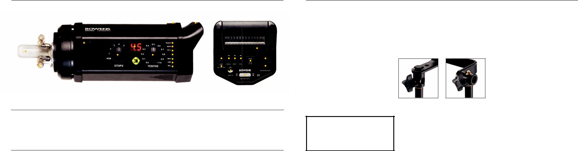
Mounting your Gemini R or Pro
Mount your monolight on a dependable support system.
The mount bush on the ‘L’ bracket allows for two possible ways of mounting to the stand/support (below).
Method B may be found useful if the light is required to point down.
NOTE: When operating from a Travelpak battery, the modelling functions are not available, this is to preserve battery life.
•Ensure the power source if off.
•Connect the unit using the appropriate cable.
•If using the Travelpak, ensure the connector locks are fully
tightened. |
|
|
• Switch the power source on, then switch on the Gemini. |
A |
B |
•The unit will charge & indicate it is ready for use by lighting the green flash-ready LED.
•Press the test button to check the unit fires.
WARNING HIGH VOLTAGE! Never connect a Gemini monolight to a Travelpak battery and AC (Mains) supply at the same time. This appliance must be grounded when used with AC. Disconnect the AC plug when changing modelling lamps and flash tubes.
User Set-Up Options
To enter the ‘user set-up options’ hold down the ‘flash test’ button (page 4) for 3-4 seconds when the unit is switched on.
Once the unit has entered the user set-up options the LED display will first show a continuous sequence of numbers (four sets of two numbers). Firstly the software version will be displayed (shown by a decimal point i.e. ‘1.1’), followed by a three, two-digit number sequence, representing the total flash count for that particular unit (up to 999,999). Each set of numbers in the flash count sequence will be interspersed with a dash, for instance 00-15-76 (representing 001,576 flashes).
Once the LED display had cycled through the software version and the total flash count, the unit will then activate the ‘user set-up options’.
The ‘1/10-stop (TENTHS) power adjust dial’ is used to select the required function / option for review or change.
Once a user set-up option is selected using the TENTHS dial, |
Operation |
|
|
||
the LED display will show the current setting. |
|
|
To cycle through / change the setting for any user set-up |
| |
|
option, press the ‘modelling lamp function switch’ (page 4) at |
Pro |
|
|
||
the rear of the unit either up or down. |
R and |
|
|
||
Once all the user set-up options have been reviewed or |
Gemini |
|
changed as required, press the ‘flash test’ button to save the |
||
|
||
amended settings and reboot the unit to normal operation. |
5 - |
|
|
 Loading...