

Page 1
Reference Series
High Performance Floorstanding Speakers
VR-M80
VRM80/90 manual v3 11/28/01 12:58 PM Page 1
Page 2
2
Specifications VR-M90 VR-M80
Frequency Response (±3dB) 36–20,000Hz 42–20,000Hz
Recommended Amplifier Power 50–350 watts 50–250 watts
Nominal Impedance 8 ohms 8 ohms
Sensitivity [1 watt (2.83v) at 1m] 89dB 90dB
Bass Units 2 x 61⁄2
" (165mm) DCD copolymer 2 x 5
1
⁄4
" (135mm) DCD copolymer
Midrange 31⁄2"
(89mm)
Tweeter 1
" (25mm) black anodized 1
" (25mm) black anodized
aluminum dome with AMD aluminum dome with AMD
Crossover Frequency 350, 2500Hz 2500Hz
Dimensions (HxWxD) 371⁄4 x 91⁄4 x 14" (946 x 235 x 357mm) 333⁄4 x 91⁄4 x 12" (857 x 235 x 305mm)
Weight 65 lbs. (29.5kg) 58 lbs. (26.3kg)
Finish Cherry wood veneer with Cherry wood veneer with
cast aluminum baseplate cast aluminum baseplate
Description
The VR-M80 and VR-M90 are monitor-quality floorstanding speakers designed to deliver accurate, natural reproduction,
with an elegant appearance. All the exposed surfaces of the VRM-80 and VR-M90 are clad in a hand-rubbed cherry hardwood veneer. Extra thick, 1
1
⁄8-inch MDF is used for the cabinet side walls, to maximize cabinet rigidity and minimize
coloration. A vertical brace runs the entire height of both cabinets, to further reduce unwanted cabinet resonance. The rearmounted vent is smoothly flared at both ends to reduce port turbulence, and both speakers feature dual gold-plated
binding posts, allowing bi-wiring or bi-amping with virtually any cable.
Special care has been taken to optimize the speakers’ components for maximum performance: The bass units utilize diecast aluminum baskets that keep the critical moving parts in precise alignment for exceptionally accurate response. The
cast baskets also conduct heat away from the voice coil, increasing power handling and maximizing output. The woofer
cones and surround geometry were designed and optimized with Boston’s Finite Element Analysis (FEA) computer
modeling technology, for strong bass and smooth midrange. High frequencies are handled by Boston’s patented 1-inch
(25mm) aluminum tweeter with Amplitude Modification Device
™
(AMD). This remarkable driver produces an extremely
smooth, flat response well beyond the audible range. A die-cast, multi-finned aluminum heatsink attached to the
tweeter’s backplate dissipates heat quickly and efficiently, assuring cool, trouble-free operation, even at very high power
levels. All the drive units are designed at Boston’s Peabody, Massachusetts facility using state-of-the-art computer-design
programs, and are built on Boston’s proprietary production lines to an incredible ±1dB—perhaps the industry’s tightest
tolerance. Both systems feature MagnaGuard
®
magnetic shielding for compatibility with home theater systems. A new
3
1
⁄2-inch (89mm) midrange driver is being used for the first time in the VR-M90. Its cast-aluminum basket has an integrated
yoke for its neodymium magnet, assuring extraordinary heat dissipation characteristics. The injection molded polypropylene
cone is molded with the surround, eliminating a glue joint. This reduces the mass of the moving parts of the driver, and
improves power handling and high frequency performance.
The crossovers for the VR-M80 and VR-M90 have been enhanced to maximize sound quality and improve power handling.
An extra-thick glass epoxy printed circuit board supports thicker traces. The connecting wires are 16 gauge, and all
connections are gold plated.
The cast aluminum base plate provides additional coupling of the speaker to the floor, while enhancing its handsome
aesthetic. Each speaker is furnished with height adjustable, rubber capped feet as well as two lengths of carpet spikes. Also
included are gold-plated hex caps, for a more elegant appearance.
VRM80/90 manual v3 11/28/01 12:58 PM Page 2
Page 3
3
How to Connect Your Speakers
Correctly wiring your speakers is important for achieving the best sound quality. Wiring should take just a few
minutes, but it’s important to do it carefully, since incorrect wiring (such as reversed connections) can result in a poor
soundstage and poor bass.
We recommend 16-gauge wire or thicker for runs up to 15 feet (4.5m), and 14-gauge wire or thicker for longer runs.
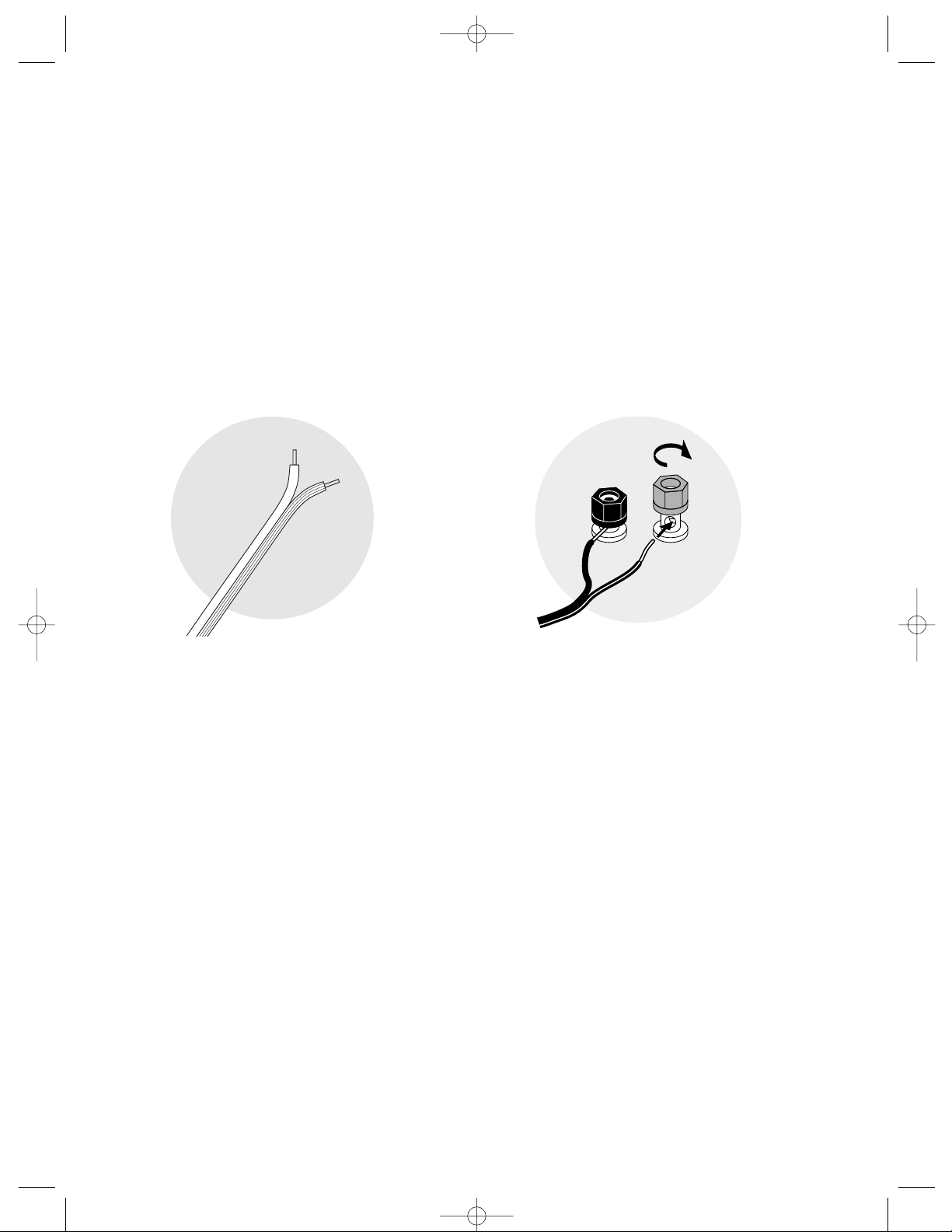
(see Speaker Cable section on page 5). Separate the first few inches of the wire conductors. Strip off
1
⁄2" (12mm)
of insulation from the ends of each speaker wire to expose the two conductors and tightly twist the wire strands.
WARNING: To prevent electrical shock hazard, always switch off the amplifier or receiver when making connections
to the speaker.
When making all connections, be sure to connect the + (red) on the speaker to the + (red) on the amplifier, and the
– (black) on the speaker to the – (black) on the amplifier.
IMPORTANT: Typically, one side of the wire is smooth.
Connect this side to the – (black) connection. The
other side has a rib or stripe. Connect this to the
+ (red) connection.
Using the five-way binding posts: The binding posts
permit easy connection to banana plugs, spade lugs,
and bare wire.
Insert the wire in the hole and tighten.
Checking the Speaker Connections
It is important that your speakers are hooked up with similar polarity or “in phase.” A simple listening test will tell
you if your speakers are connected properly. Place the speakers face to face, as closely together as possible. While
listening to music with your amplifier set to MONO, reverse the connections at one speaker only. You’ll hear a
dramatic change in sound. The connection that yields the fuller bass and louder sound is correct.
VRM80/90 manual v3 11/28/01 12:58 PM Page 3
Page 4

4
speaker terminal with
jumper strap in place
amplifier or receiver
Basic Hookup
1. Connect the speaker terminals to the amplifier
speaker outputs.
2. Make sure the speaker terminal jumper straps are in
place on the back of the speaker.
3. When making all connections, be sure to connect
+ to + (red) and – to – (black).
Bi-wiring
Bi-wiring increases the flow of current and decreases intermodulation of different frequencies by providing separate inputs to the
woofer and midrange/tweeter sections. Bi-wiring will usually
improve the sound quality, although the improvement may be quite
subtle. If you choose to bi-wire, use the same type and length of wire
for all connections. When making all connections, be sure to connect + to + (red) and – to – (black).
1. Unscrew both sets of terminals and remove the
jumper straps.
2. Connect the wires from the amplifier’s speaker
terminals to each individual set of terminals on the
back of the speaker as shown.
Connecting the VR-M80 or VR-M90 to Your Amplifier or Receiver
VRM80/90 manual v3 11/28/01 12:58 PM Page 4
amplifier or receiver
Page 5

5
Bi-amplification
Bi-amplification requires using separate amplifiers dedicated to high and low frequencies. Using more than one
amplifier can enhance the dynamic performance of your system. “Splitting the load” between two amplifiers lets
each amplifier work less hard, increasing the available current to the drive units. When making all connections, be
sure to connect + to + (red) and – to – (black).
1. Unscrew the terminal collars of both sets of terminals and remove the connector straps.
2. Connect the wires from the bottom set of terminals to the amplifier driving the woofers.
3. Connect the wires from the top set of terminals to the amplifier driving the midrange/tweeter.
CAUTION: Do not use an external active crossover with your VR-M speakers. The external crossover and the VR-M’s
internal crossover can interact and distort the phase and frequency response of the system.
Speaker Cable
You should always use high quality speaker cable for optimum audio results. The thickness or gauge of the cable
is equally important. Use the following length to diameter guidelines to maintain the minimum gauge for a
particular length:
Length Diameter Gauge
Less than 15ft. (4.5m)
3
⁄64 in. (1.3mm) 16 awg
Less than 30ft. (9m)
1
⁄16 in. (1.6mm) 14 awg
More than 30ft. (9m)
5
⁄64 in. (2.0mm) 12 awg
VRM80/90 manual v3 11/28/01 12:58 PM Page 5
right speaker
left speaker
low frequency amplifier
high frequency amplifier
Page 6

6
How to Place Your Speakers
The VR-M80 and VR-M90 were designed to deliver exceptional bass extension and tonal balance, regardless of
where they are placed. However, for optimal results, it is advisable to position the rear of the speaker to be at least
3 inches (76cm) or more away from the wall or curtains that are behind it. The speakers should also be at least 2 feet
(0.6m) from the corners of the room. Putting the speakers too close to a corner can produce an unnatural bass
reinforcement that detracts from their balanced, uncolored sound. For optimal bass performance when a speaker
must be placed in or near a corner, position it so that the distance to the side wall is different than the distance to
the rear wall.
Most people like to hear a realistic soundstage, as they would from a good seat in a concert hall. To achieve this
effect, place the speakers 6 to 12 feet (2-4m) apart, so they form a triangle with your favorite listening position.
If your listening position happens to be less than the distance that the speakers are apart, then you may prefer to
“toe-in” the speakers slightly.
6 to 12 feet
(2 to 4m)
2 feet (.6m)
or greater
3 inches (76cm)
or greater
Listening Room Considerations
The listening room’s dimensions, furnishings and wall types will all contribute to the way any loudpeaker will
respond. If your room is square (same length and width), you may experience low frequency standing waves that
can reduce overall clarity. Experiment with different placements and toe-ins to avoid this. Also, the more fabric
material there is in a room (curtains, sofas carpets, etc), the more that high and mid-range frequencies will be
dampened. Conversely, the more exposed bare walls that there are in the room, the brighter the speakers will
sound. Thus, you may also want to experiment with speaker placements with these considerations in mind.
VRM80/90 manual v3 11/28/01 12:58 PM Page 6
Boston
Boston
567
4
8
3
9
2
10
1
11
volume0
12
80 120set none 0°180 °
50 150
crossover Hz crossover polarity
Page 7

7
Leveling Your Speakers and Adjusting the Height of the Sonic Image
The cast aluminum base plate provides additional coupling of the speaker to the floor by utilizing height adjustable, rubber
capped feet (factory installed) or two lengths of carpet spikes which are included in the hardware bag. Both the feet and
the spikes are threaded through the base plate and can therefore can be screwed in or out to change the speaker’s height
at each corner.
Independently adjusting the height of each corner can serve two functions:
1) Leveling a speaker that is placed on an uneven floor surface.
2) Raising or lowering the sonic image of the speaker.
While these speakers have been designed to have exceptional vertical dispersion, by changing their “rake” or audio
projection angle, you can optimize their sonic image to your preferred listening height. If your seating position is in a low
slung chair or sofa, you may want to rake the speaker slightly forward. If you listen in taller chairs or sofas or prefer to stand
a lot or move about the room, then you may want to rake the speaker slightly backward.
Refer to the diagram below on how to change the height or projection angle of your speakers using the rubber capped
feet. The process is the same using the spikes except there is no hex nut, thus the included wrench will not be used.
Instead, the spike features a knurled surface at the end of its threaded section to facilitate screwing it in or out using your
fingers.
IMPORTANT: Whether you use the rubber capped feet or the carpet spikes, be sure to remove the decorative gold-plated
hex cap nuts before you make your adjustments. Once your adjustments are final, replace the cap nut and tighten it firmly
by hand, locking your setting into place.
Listening Levels and Power Handling
The listed power recommendations in the Specifications section assume you will operate your system in a way that
will not produce distortion. Even these rugged speakers can be damaged by a modest amplifier if it produces
distortion. If you hear a harsh, gritty noise, turn down the volume. Prolonged or repeated operation of your speaker
with a distorted signal from the amplifier can cause damage that is not covered by the warranty.
VRM80/90 manual v3 11/28/01 12:58 PM Page 7
IMPORTANT!
Remove gold-plated
hex cap nuts before
adjusting height
Turn to lower
Engage wrench
on to hex nut
Turn to raise
Page 8

300 Jubilee Drive
Peabody,
MA 01960 U.S.A.
978.538.5000
VR and AMD are trademarks and MagnaGuard, Boston,
and Boston Acoustics are registered trademarks of
Boston Acoustics, Inc.
© 2001 Boston Acoustics, Inc. All rights reserved.
Specifications subject to change without notice.
042-001219-1
www.bostonacoustics.com
Limited Warranty
For five years from the date of purchase, Boston Acoustics will repair for the original owner any defect in materials
or workmanship that occurs in normal use of the speakers, without charge for parts and labor.
Your responsibilities are to use the system according to the instructions supplied, to provide safe and secure
transportation to an authorized Boston Acoustics service representative, and to present proof of purchase in the
form of your sales slip when requesting service.
Excluded from this warranty is damage that results from abuse, misuse, accidents, shipping, or repairs or modifications by anyone other than an authorized Boston Acoustics service representative.
This warranty is void if the serial number has been removed or defaced.
This warranty gives you specific legal rights, and you may also have other rights which vary from state to state.
If Service Seems Necessary
First, contact the dealer from whom you purchased the speakers. If that is not possible, write to:
Boston Acoustics, Inc. 300 Jubilee Drive Peabody, MA 01960 U.S.A.
We will promptly advise you of what action to take. If it is necessary to return your speaker to the factory, please
ship it prepaid. After it has been repaired, we will return it freight prepaid in the U.S.A. and Canada.
Grille Removal Instructions
1) Grasp both ends of plastic strip and gently pull to start
2) Use fingers to gradually pull grille away from cabinet
3) Work up both sides at once to remove
4) Plastic strip can be left in grille for future removals
We recommend keeping the grille on the cabinet to protect the speaker
and maintain its proper appearance. If you must remove the grille, please
follow these instructions:
If you are leaving the grille on, just pull the plastic strip out from either side.
Caution!
DO NOT USE TOOLS. This speaker cabinet is constructed from furniture
grade cherry wood veneer. Please be careful not
to scuff the fine lacquer finish when removing or
replacing the grille.
VRM80/90 manual v3 11/28/01 12:58 PM Page 8
 Loading...