

Page 1

VR1, VR2
VRC
VR1
VR1, VR2, VR3
VRB, VRC
High Performance Home Theater Loudspeakers
Page 2

Specifications VR1
Frequency Response (±3dB) 46Hz-20kHz
VR2 VR3
41Hz-20kHz 41Hz-20kHz
Recommended Amplifier Power 15-150 watts 15-150 watts 15-150 watts
Nominal Impedance 8 ohms
Sensitivity [1 watt (2.83v) at 1m] 93dB
Bass Unit (2) 6
1
⁄2" DCD™(165mm) copolymer (2) 61⁄2" DCD™(165mm) copolymer (2) 61⁄2" DCD™(165mm) copolymer
Midrange -4
Tweeter 1" (25mm)
aluminum dome with AMD
VR
H.O.™anodized
Crossover Frequency 2700Hz
Dimensions (H x W x D) 36 x 9 x 10
(915 x 229 x 267mm) (966 x 229 x 293mm) (966 x 229 x 293mm)
1
⁄2" 38 x 9 x 111⁄2" 38 x 9 x 111⁄2"
8 ohms 8 ohms
93dB 93dB
1
⁄2" (115mm) neodymium copolymer 41⁄2" (115mm) neodymium copolymer
1" (25mm) VR
™
aluminum dome with AMD
400, 2800Hz 400, 2800Hz
H.O.™anodized
™
1" (25mm) VR
aluminum dome with AMD
Weight 40 lbs (19kg) 45 lbs (21kg) 45 lbs (21kg)
VRB VRC
Frequency Response (±3dB) 48Hz-20kHz 70Hz-20kHz
Recommended Amplifier Power 15-150 watts 15-150 watts
Nominal Impedance 8 ohms 8 ohms
Sensitivity [1 watt (2.83v) at 1m] 92dB 92dB
Bass Unit 7" DCD
Midrange -4
Tweeter 1" (25mm) VRH.O.
™
(180mm) copolymer (2) 41⁄2" (115mm) neodymium copolymer
1
⁄2" (115mm) neodymium copolymer
™
anodized 1" (25mm) VRH.O.™anodized
TM
aluminum dome with AMD
aluminum dome with AMD
TM
Crossover Frequency 2400Hz 500, 2800Hz
Dimensions (H x W x D) 16
7
⁄8 x 73⁄4 x 12" 5 x 22 x 8"
(427 x 197 x 304mm) (129 x 559 x 205mm)
H.O.™anodized
™
Weight 21lbs (10kg) 19 lbs (9kg)
Description
The VR1, VR2, and VR3 compact fl
of power
ful, impr
The high-per
essive sound usually associated only with much lar
mance VRC is a timbre-matched center channel speaker that is a perfect compliment to any of the VR floorstanding
for
models in your home theater system. The VRC’s three-way design delivers extremely wide horizontal dispersion and exceptionally
high power handling capability.
All three VR floorstanding models feature dual woofers for deep, authoritative bass response and low distortion. The placement
of the woofers on the baffle has been chosen with extreme care and precision, and it provides two very specific, clearly audible
benefits: First, by separating the woofers by a precisely calculated distance, the internal "pipe organ" standing wave—common
to all columnar
of audible insignifi
2
-type enclosur
cance. The r
oorstanding speaker systems and the VRB compact bookshelf speaker system deliver the kind
e expensive speakers.
, mor
ger
es that have their bass drivers closely gr
esult is less midrange coloration and a commensurate incr
ouped at one end of the cabinet—is reduced to the point
ease in clarity and detail.
Page 3
The second benefit is smoother, more uniform upper bass/lower midrange frequency response in a real listening room.
The dimensional r
elationship of the woofer to the nearby room boundaries (the walls and floor) in any speaker results in
a reinforcement or cancellation of upper bass/lower midrange frequencies corresponding to the woofer-to-boundary distances. By placing the cabinet’s two woofers at optimally chosen different locations, these dimensions are "averaged" over
a wider variety of distances, ther
eby reducing the influence of any single woofer-to-boundary dimension. The result is much
smoother, more accurate in-room frequency response, with far less of the typical "peak and dip" characteristic found in
conventional designs.
The 3-way models utilize a newly-developed 4
1
⁄2-inch (115mm) midrange driver with a large 11⁄2-inch voice coil for superb
driver control and extremely high power handling. Its powerful neodymium magnet produces 10 times more magnetic
energy than a conventional magnet of the same size, but its compact dimensions allow the tweeter and midrange to be
mounted very close together for seamless, perfectly integrated sound with wide, uniform dispersion. A high output 1-inch
(25mm) anodized aluminum VR tweeter, with our exclusive patented Amplitude Modification Device (AMD) produces extended, sparkling high frequencies.
The cabinets have extensive internal bracing and are constructed of Medium Density Fiberboard (MDF), chosen for its favorable acoustic characteristics. The result is superb structural integrity that eliminates the spurious resonances and vibration
that degrade the sound of ordinary speakers.
MagnaGuard
®
magnetic shielding ensures the speakers’ magnetic field does not interfere with the television’s picture, allow-
ing placement next to a TV in a home theater system.
How to Connect Your Speakers
Correctly wiring your speakers is important for achieving the best sound quality. Wiring should take just a few
minutes, but it’s important to do it carefully, since incorrect wiring (such as reversed connections) can result in a poor
soundstage and poor bass.
We recommend 18-gauge wire or thicker for runs up to 25 feet (8m), and 16-gauge wire or thicker for longer runs.
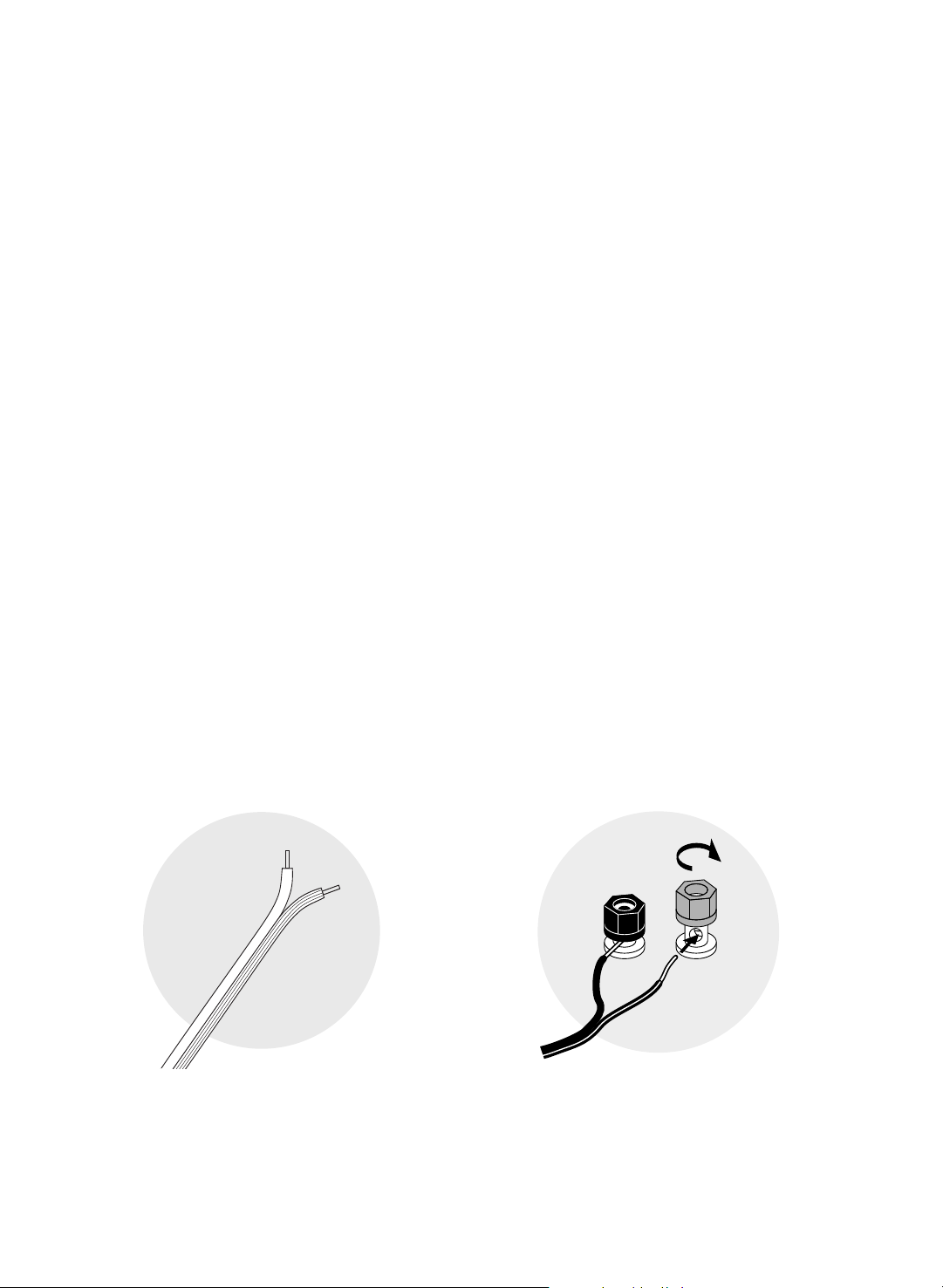
Separate the first few inches of the wire conductors. Strip off
1
⁄2" (12mm) of insulation from the ends of each speaker
wire to expose the two conductors and tightly twist the wire strands.
When making all connections, be sure to connect the
+ (red) on the speaker to the + (red) on the amplifier, and the –
(black) on the speaker to the – (black) on the amplifier.
WARNING: To prevent electrical shock hazard, always switch off the amplifier or receiver when making connections
to the speaker.
IMPORTANT: Typically, one side of the wire is smooth.
Connect this side to the
– (black) connection. The
other side has a rib or stripe. Connect this to the
+ (red) connection.
Using the five-way binding posts: The binding posts
mit easy connection to banana plugs, spade lugs,
per
and bare wire.
Insert the wire in the hole and tighten.
3
Page 4

VR1/VRB VR2 or VR3
Speaker terminal
jumper straps in place
VRC
surround sound receiver or amplifier
left front
center front right front
Connecting the Speakers to Your Amplifier or Receiver
VR2 or VR3
amplifier or receiver
Remove jumper
straps
Basic Hookup
1. Connect the speaker terminals to the amplifier speaker outputs.
2. Make sure the speaker terminal jumper straps are in place on the back of the speaker. (VR2 and VR3 only)
IMPORTANT: When making all connections, be sure to connect + to + (red) and – to – (black).
Bi-wiring (VR2, VR3 only)
Bi-wiring increases the flow of current and decreases intermodulation of different frequencies by providing separate inputs
to the woofer and midrange/tweeter sections. Bi-wiring will usually improve the sound quality, although the improvement
may be quite subtle. If you choose to bi-wire, use the same type and length of wire for all connections. When making all
connections, be sure to connect
1. Unscrew both sets of terminals and remove the jumper straps.
2. Connect the wir
es from the amplifier’s speaker terminals
to each individual set of terminals on the back of the speaker as shown.
+ to + (red) and – to – (black).
4
Page 5

Bi-amplification (VR2 and VR3 only)
right VR2 or VR3
lef
t VR2 or VR3
low-frequency amplifier
high-frequency amplifier
Remove jumper straps
Bi-amplification requires using separate amplifiers dedicated to high and low frequencies. Using more than one
amplifier can enhance the dynamic performance of your system. “Splitting the load” between two amplifiers lets
each amplifier work less hard, increasing the available current to the drive units. When making all connections, be
sure to connect
1. Unscrew the terminal collars of both sets of terminals and remove the jumper straps.
2. Connect the wires from the bottom set of terminals to the amplifier driving the woofers.
3. Connect the wires from the top set of terminals to the amplifier driving the midrange/tweeter.
+ to + (red) and – to – (black).
CAUTION: Do not use an external active crossover with your VR speakers. The external crossover and the VR’s
internal crossover can interact and distort the phase and frequency response of the system.
5
Page 6

How to Place Your Speakers
volume0
1
2
3
4
567
8
9
10
11
12
crossover Hz crossoverpolarity
50 150
80 120 set none 0° 180°
Boston
The VR speakers wer
However, for optimal results, it is advisable to position the
wall or curtains that are behind it. The speakers should also be at least 2 feet (0.6m) from the corners of the room. Putting
the speakers too close to a corner can produce an unnatural bass reinforcement that detracts from their balanced, uncolored sound. For optimal bass performance when a speaker must be placed in or near a corner, position it so that the distance to the side wall is different than the distance to the rear wall.
e designed to deliver exceptional bass extension and tonal balance, regardless of where they are placed.
rear of the speaker to be at least 3 inches (76mm) away from the
Most people like to hear a r
ealistic soundstage, as they would from a good seat in a concert hall. To achieve this effect, place
the speakers 6 to 12 feet (2-4m) apart, so they form a triangle with your favorite listening position. If your listening position
happens to be less than the distance that the speakers are apart, then you may prefer to “toe-in” the speakers slightly.
Place the VRC center channel speaker as shown below, with the front of the speaker flush with the front of the television.
The VRC is specially tuned to sit atop of a large, flat TV screen. This is quite important, since the TV screen surface acts as
a large baffle that can alter a speaker’s sound, degrading both dialogue and music. Four self-adhesive rubber feet are provided to protect the TV’s finish and prevent vibration.
Listening Room Considerations
The listening r
oom’
s dimensions, fur
nishings and wall types all contribute to the way a loudspeaker sounds. If your r
oom
is square (same length and width), you may experience low frequency standing waves that can reduce overall clarity.
Experiment with different placements and toe-in to avoid this. Also, the more fabric material there is in a room (curtains,
sofas, carpets, etc), the more that high and midrange frequencies will be dampened. Conversely, the more exposed bare
walls there are in the room, the brighter the speakers will sound. Thus, you may also want to experiment with speaker placements with these considerations in mind.
6
Page 7

or
Using the Carpet Spikes
For placing speakers on thick carpet, we recommend using the four threaded carpet spikes and lock nuts (VR2
and VR3 only) which serve three purposes — leveling (an aesthetic issue), stability (a practical issue) and rigidity
(an acoustic issue). The spikes concentrate the speaker’s weight on four points, creating focused pressure that
anchors the speaker cabinet to the fl
of the carpet spike exposed is sufficient, although this may be adjusted as necessary.
For placing the speakers on hard, flat surfaces, use the four circular self-adhesive rubber pads provided instead of
the carpet spikes.
oor and enhances rigidity. For most carpeting, leaving about
1
⁄2-inch (12mm)
Mounting the VRB to a Speaker Stand
The VRB features a 1/4"-20 threaded insert on the bottom panel, so it can be securely bolted to any accessory speaker
stand that offers this feature. Bolting the speaker to the stand reduces unwanted vibration and reduces the possibility
of the speaker accidentally falling off the stand.
Caring for Your Speakers
The cabinet of your VR Speaker system is finished in furniture-grade vinyl veneer. This finish should be treated like
any other piece of fine furniture. To clean, simply wipe lightly with a slightly damp cloth. Do not use abrasive cleaners, solvents, wax, oil or furniture polish.
Listening Levels and Power Handling
The listed power recommendations assume you will operate your system in a way that will not produce distortion. Even
these rugged speakers can be damaged by a modest amplifier if it produces distortion. If you hear a harsh, gritty noise,
turn the volume down. Prolonged or repeated operation of your speaker with a distorted signal from the amplifier can
.
cause damage that is not cover
ed by the war
ranty
7
Page 8

300 Jubilee Drive
Peabody,
MA 01960 USA
978.538.5000
bostonacoustics.com
AMD is a trademark and DCD, VR, MagnaGuard,
Boston, and Boston Acoustics are registered
trademarks of Boston Acoustics, Inc.
© 2004 Boston Acoustics, Inc. All rights r
Specifications subject to change without notice.
042
eser
-
ved.
728-1
1
0
0
 Loading...