


1
Instruction Manual
TPSRF31 (181430) - BOSSTM Electronic RF Roomstat
Thank you for purchasing this product. If installing for someone else, please ensure that the
instructions are handed to the householder.
Please read this manual prior to installation or use.
Always isolate the mains power supply before removing the unit from the backplate.
Do not mix old and new batteries. Do not use rechargeable batteries.
Please leave these instructions with the end user where they should be kept in a safe place for
future reference.
Installation
The TPSRF31 Control Unit is easily installed using the backplate supplied. This is used purely for
mounting, as no wiring is needed for the Control Unit. The backplate can be mounted directly to
the wall without a back box.
The ideal position to locate the TPSRF31 Control Unit is about 1.5m above floor level. It should be
mounted in a location where the thermostat is accessible, reasonably lit and free from extremes of
temperature and draughts. Do not mount the thermostat on an outside wall, above a radiator or in
a location where it may be subjected to direct sunlight.
To ensure trouble free receiving of the Radio Frequency (RF) signal, always ensure that the
thermostat is mounted away from any possible sources of interference (such as radio, TV sets,
computer, etc.), the location of TPSRF31 in enclosed areas such as cellars and basements is not
recommended, it should be positioned where the temperature sensed is representative of the zone
being controlled.
Connecting the TPSRF31 Receiver
NOTE: All electrical installation work should be carried out by a suitably qualified Electrician or other
competent person.
If you are not sure how to install this digital thermostat consult either with a qualified electrician,
heating engineer or your boiler/heating system supplier for advice on how to proceed.
The TPSRF31 Receiver should be mounted in a suitable location that is both accessible for the
connection of mains and control wiring, and allows good reception of the RF signal. The Receiver
needs a 230V AC mains supply to operate, and this should be fused appropriately (13A max.)
The Receiver should be mounted in a location where it will not come into contact with water,
moisture or condensation.
The Receiver On/Off switch is accessible from the front face of the Receiver.
On the front cover of the Receiver you will see that there is the On/Off switch and two Light
Emitting Diodes (LEDs). The switch allows you to turn off the Receiver if necessary to prevent it
calling for heat. The top LED (orange) will illuminate when the switch is in the “On” position and
the unit is receiving power. The bottom LED (green) illuminates when the Receiver unit is receiving
a heat call transmission from the Control Unit.
2
The wiring terminals and RF Address Code setting DIP switches are located on the rear of the
Receiver.
Receiver Wiring Terminals
Terminal Name Function
N Neutral input 230VAC/50Hz
L Live input 230VAC/50Hz
1: COM Switch common terminal
2: NO Normal open (Volt-Free Contact)
3: NC Normal close (Volt-Free Contact)
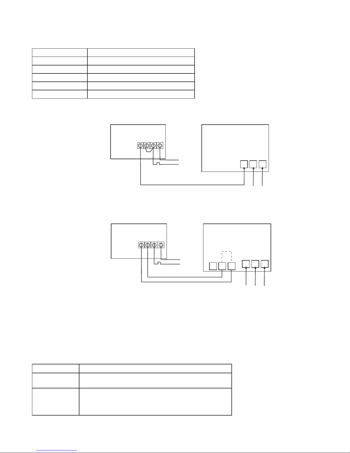
Direct Control Boiler
Notes: Receiver unit should have a permanent 230V AC main supply
Combi Boiler
Notes: • Receiver unit should have a permanent 230V AC main supply
• If the boiler has two terminals for the thermostat, remove the link from the boiler
Control Unit Jumper Settings
Changes to the jumper settings should only be made by the Engineer carrying out the installation
or other qualified person.
The installer should select the jumper positions required if changes need to be made to the factory
default settings. These jumpers are found on the rear of the Control Unit.
Jumpers Description
Address code
5 DIP switch levers for 5 bits address code for
RF communication (All jumpers default are closed)
Span
3x1 pins jumper for +/-0.5°C or 1.0°C
(factory default setting) selection.
It is used to define the system to run at +/-0.5°C or 1.0°C
difference to the set temperature
Notes : The Reset button must be pressed after changing jumper positions.
The Reset button is accessible behind the small hinged door on the front right hand side of the Control Unit.
RECEIVER
N.0. COM L N
N
L
BOILER
Live Feed
L N E
MAINS
FEED
N L SL
Thermostat (Remove link)
Green/YellowBlue
Brown
Brown
Brown
Brown
Blue
RECEIVER
N.0. COM L N
N
L
BOILER
Live Feed
N E
L N E
MAINS
FEED
YellowBlue
Brown
Brown
Brown
Blue
 Loading...