

Page 1
Reference Manual
© 2019 Roland Corporation
01
Page 2

Contents
Getting Ready ........................ 4
Connecting the Equipment ............ 4
Turning the Power On/O .............. 4
Auto O Function ..................... 4
Panel Descriptions ..................... 6
Selecting the Instrument (Guitar/
Bass) to Use (MODE SETTING) .......... 7
Specifying the Device Connected to
OUTPUT Jacks (OUTPUT SELECT) ....... 7
Making Pickup Settings (GK SETTING) .. 8
Specifying the Pickup Type ............ 8
Specifying Your Guitar’s (Bass’s) Scale
Length
............................... 9
Specifying the Pickup Position (Bass
Mode Only) .......................... 9
Specifying the Distance from the
Bridge .............................. 10
Adjusting the Pickup Sensitivity. . . . . . . 10
Tuning the Guitar (TUNER) ............ 10
Making Tuner Settings ............... 10
Basic Operation ..................... 11
Display (Play Screen) .................. 11
About the Icons. . . . . . . . . . . . . . . . . . . . . . 11
Screen Operations .................... 12
Operating Example 1 (INST Screen) ... 12
Operating Example 2 (INST Edit
Screen) .............................. 12
Operating Example 3 (EFFECT Edit
Screen) .............................. 12
Switching Patches (Tone) ........... 13
The Structure and Patches of the SY-
1000 .................................13
Types of Bank ........................13
Types of Patch .......................13
Selecting a Patch .....................13
Editing a Patch ...................... 14
Changing the INST .................... 14
Editing the INST ......................14
Viewing All Parameters While You Edit . 14
Saving the Edited INST Settings
(VARIATION) .......................... 15
Recalled a Saved INST Variation ....... 15
Editing the Eects .................... 16
Basic Operation for Eect Editing ..... 16
Editing While Viewing All Parameters .. 16
Changing the Eect Order ............ 16
Saving the Edited Eect Settings
(VARIATION)
Recalled a Saved Eect Variation ...... 17
Assigning Functions to the Foot
Switches and Expression Pedal ........18
Making Assignments from the Eect
Edit Screen (Quick Assign)
.......................... 17
............ 18
Saving a Patch. . . . . . . . . . . . . . . . . . . . . . . 19
Settings for the Entire SY-1000
(System Parameters)
Settings for the SY-1000 ..............20
Restoring the Factory Default
Settings (Factory Reset) .............. 20
Turning O the Auto O Function ..... 20
................ 20
2
The Internal Structure of the SY-
1000 ................................. 21
INST (Instrument) Block ............... 21
EFFECT (Eects) Block ................. 21
INST Parameters .................... 22
Availability of Functions for Each
INST TYPE (GUITAR MODE) ............ 22
Availability of Functions for Each
INST TYPE (BASS MODE) .............. 22
INST TYPE ............................23
Parameters Common to Each INST
TYPE (COMMON) .................... 23
Parameters Common to Each INST
TYPE (ALT TUNE) ..................... 24
DYNAMIC SYNTH Parameters .......... 25
OSC ................................. 25
FILTER ............................... 26
AMP ................................ 26
LFO1, LFO2 .......................... 27
SEQ ................................. 27
LAYER ............................... 29
OSC SYNTH Parameters ............... 29
OSC ................................. 29
FILTER ............................... 30
AMP ................................ 31
LFO1, LFO2 .......................... 31
GR-300 (In GUITAR MODE) / ANALOG
GR (In BASS MODE) Parameters .......32
GR-300/ANALOG GR ................. 32
E.GUITAR Parameters ................. 33
GUITAR (In GUITAR MODE) ............ 33
GUITAR (In BASS MODE) ..............33
AMP (AMP Modeling) ................ 34
NS .................................. 35
EQ .................................. 35
ACOUSTIC Parameters ................36
ACOUSTIC ........................... 36
AMP (AMP Modeling) ................ 37
NS .................................. 37
EQ .................................. 37
AC BASS Parameters .................. 37
AC BASS ............................. 37
AMP (AMP Modeling) ................ 37
NS .................................. 37
EQ .................................. 37
E.BASS Parameters .................... 38
BASS (In GUITAR MODE) ..............38
BASS (In BASS MODE) ................ 38
AMP (AMP Modeling) ................ 39
NS .................................. 39
EQ .................................. 39
VIO GUITAR Parameters ............... 39
GUITAR ..............................39
HARMO ............................. 40
FILTER ............................... 40
NS .................................. 40
EQ .................................. 40
POLY FX Parameters .................. 41
NS .................................. 41
EFFECT Parameters .................42
FX1–FX3 .............................. 42
AC RESONANCE. . . . . . . . . . . . . . . . . . . . . . 43
AUTO WAH .......................... 43
CHORUS ............................ 43
CLASSIC-VIBE ........................ 44
COMPRESSOR ....................... 44
DEFRETTER .......................... 44
DEFRETTER BASS .................... 45
DELAY .............................. 45
FLANGER/FLANGER BASS ............. 46
FOOT VOLUME .......................46
GRAPHIC EQ ......................... 47
HARMONIST ......................... 47
HUMANIZER ......................... 48
ISOLATOR ........................... 48
LIMITER ............................. 48
LO-FI ................................ 48
OCTAVE/OCTAVE BASS ............... 49
PAN ................................. 49
PARAMETRIC EQ ..................... 49
PEDAL BEND ........................ 49
PHASER ............................. 50
PITCH SHIFTER ....................... 50
REVERB ............................. 51
RING MOD .......................... 51
RO TA RY .............................51
SITAR SIM ........................... 52
SLICER .............................. 52
SLOW GEAR/SLOW GEAR BASS ........52
SOUND HOLD ....................... 52
TOUCH WAH/TOUCH WAH BASS ...... 53
TREMOLO ........................... 53
VIBRATO ............................ 53
WAH ................................ 54
AMP (AMP Modeling) ................. 54
TYPE ................................ 55
SP TYPE .............................55
MIC TYPE ............................ 55
CHORUS .............................. 56
COMPRESSOR ........................ 57
TYPE ................................ 57
DISTORTION .......................... 57
TYPE ................................ 57
EQ 1, EQ2 ............................. 58
MASTER DELAY ....................... 59
TYPE ................................ 59
DELAY 1, DELAY 2 ..................... 60
REVERB. . . . . . . . . . . . . . . . . . . . . . . . . . . . . . . 61
NOISE SUPPRESSOR .................. 62
FOOT VOLUME 1, FOOT VOLUME 2 .....62
SEND/RETURN ........................ 63
MODE ............................... 63
DIVIDER .............................. 64
MIXER ................................ 64
BALANCER 1–BALANCER 3 ............ 65
MAIN OUT/SUB OUT .................. 65
MASTER .............................. 66
NORMAL INPUT ....................... 66
CONTROL ASSIGN Parameters ......67
CONTROL FUNCTION .................67
FUNCTION .......................... 67
MODE ............................... 69
PREFERENCE. . . . . . . . . . . . . . . . . . . . . . . . . 69
Page 3

ASSIGN SETTING ...................... 70
ASSIGN 1–ASSIGN 16 ................. 70
Virtual Expression Pedal System
(Wave Pedal) .........................77
STRING1–STRING6, STR HiC–STR
LowB, STRING ALL, NORMAL IN
INPUT SENS (Input Sens) ............. 77
PATCH MIDI ........................... 78
PATCH MIDI 1–PATCH MIDI 4 ..........78
GUITAR TO MIDI/BASS TO MIDI ........79
LED COLOR ...........................80
[BANKI]/[BANKH] switch, [CTL1]/
[CTL2] switch, [1]–[4] switch, CUR
NUM ................................ 80
PREFERENCE. . . . . . . . . . . . . . . . . . . . . . . . . 80
....... 77
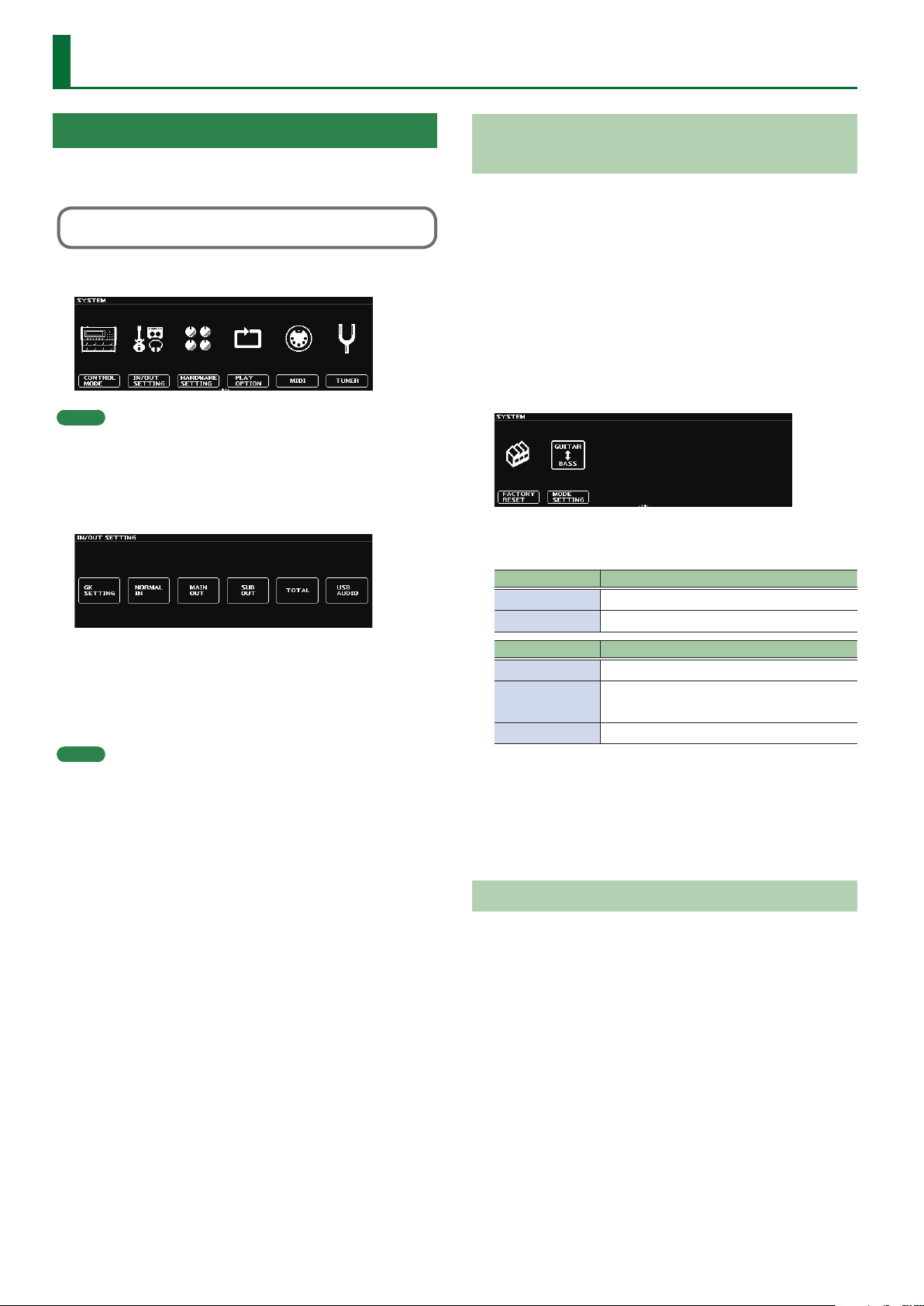
SYSTEM Parameters .................81
CONTROL MODE ...................... 81
IN/OUT SETTING ...................... 81
GK SETTING .........................81
NORMAL SETTING ................... 83
MAIN OUT, SUB OUT ................. 83
TOTAL ............................... 85
USB AUDIO .......................... 85
HARDWARE SETTING ................. 87
KNOB SETTING ...................... 87
ASSIGN HOLD .......................87
GROUND LIFT ....................... 87
OTHER .............................. 88
PLAY OPTION ......................... 88
MIDI .................................. 89
Operations from the SY-1000 ......... 89
Operations from an External MIDI
Device .............................. 89
MIDI SETTING. . . . . . . . . . . . . . . . . . . . . . . . 89
PROGRAM MAP BANK1–BANK4 ....... 90
BULK DUMP ......................... 90
GUITAR TO MIDI/BASS TO MIDI ........ 91
TUNER ............................... 91
TUNER MODE ........................ 91
FACTORY RESET ...................... 92
MODE SETTING ....................... 92
Contents
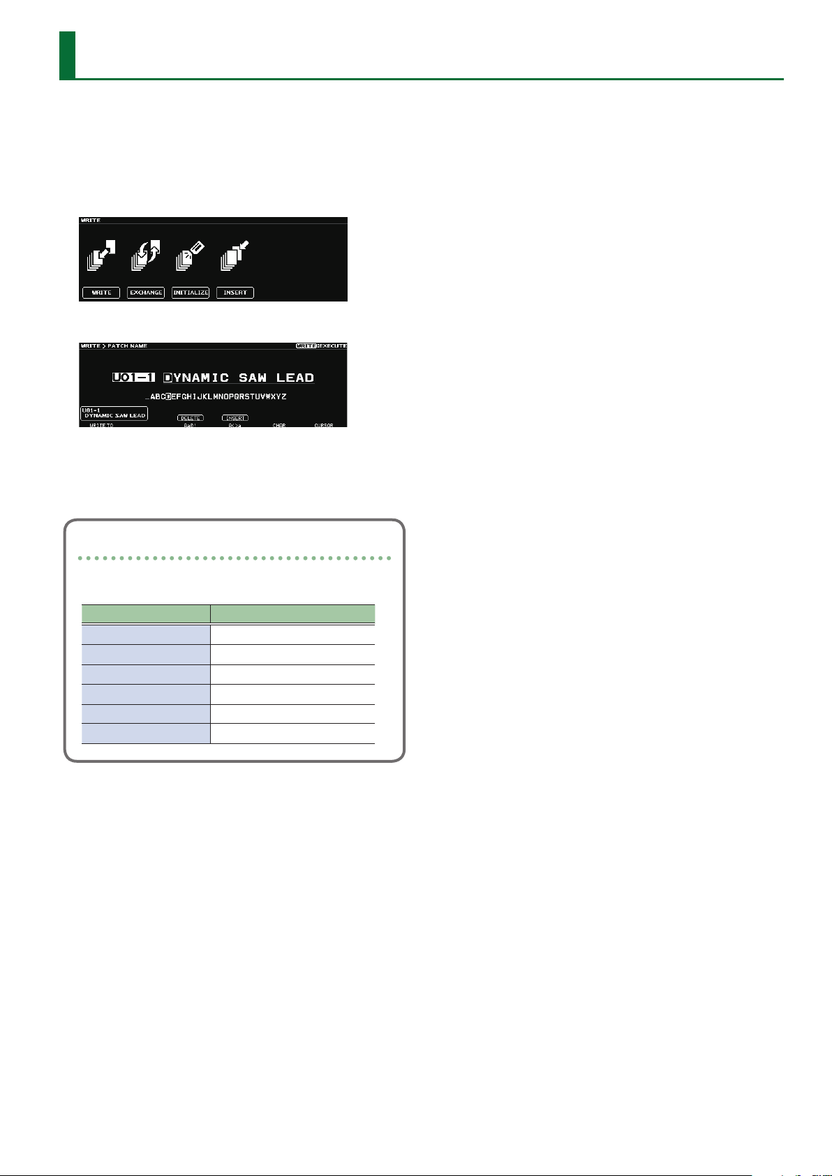
Saving a Sound (WRITE) ............ 93
Saving a Patch (PATCH WRITE) ......... 93
Exchanging Patches (PATCH
EXCHANGE)
Initializing Patches (PATCH
INITIALIZE) ...........................94
Inserting a Patch (PATCH INSERT) ...... 94
.......................... 93
Connecting to a Computer .......... 95
Installing the USB Driver .............. 95
Using the as an Audio Interface ....... 95
Troubleshooting .................... 96
When Using the SY-1000 on Its Own ... 96
When Connected to a MIDI Device or
Computer
............................ 97
Block Diagram ......................98
When Using a GK Patch ............... 98
When Using a NORMAL Patch ......... 99
3
Page 4
Getting Ready
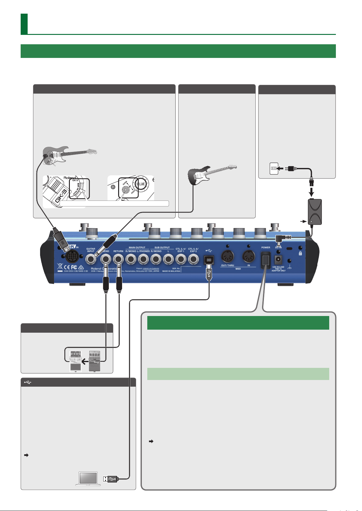
Connecting the Equipment
* To prevent malfunction and equipment failure, always turn down the volume, and turn o all the units before making any connections.
GK IN connector
Connect a guitar or bass equipped with the Roland Divided
Pickup (Roland GK-3/GK-3B) or a GK-compatible guitar such as
the Roland V-Guitar GC-1 to this connector.
In addition to the signal from the divided pickup, the
conventional guitar signal (normal pickup) is also input to the
GK IN connector.
* Never connect anything other than the dedicated GK cable.
Roland GK-3 users Roland V-Guitar GC-1 users
You must set this to the center (MIX) position!
GUITAR INPUT jack
Use this control if you’re directly
inputting a conventional guitar.
* The guitar connected to the
GUITAR INPUT jack can only
use normal patches.
* Use the “PATCH TYPE”
parameter (p. 66) to switch
to a normal patch.
DC IN jack
Connect the included AC
adaptor here.
* Place the AC adaptor so the
side with the indicator faces
upwards. The indicator will
light when you plug the AC
adaptor into an AC outlet.
Indicator
SEND/RETURN jacks
Connect an external eect
processor here.
(USB) port
Use a commercially available USB 2.0 cable to
connect this port to your computer. It can be
used to transfer USB MIDI and USB audio data.
You must install the USB driver when
connecting the unit to your computer.
Download the USB driver from the BOSS
website. For details, refer to Readme.htm which
is included in the download.
http://www.boss.info/support/
For details on the settings, refer to
“Reference Manual” (PDF).
4
Turning the Power On/O
This turns the power on/o.
* Before turning the unit on/o, always be sure to turn the volume down. Even with
the volume turned down, you might hear some sound when switching the unit on/
o. However, this is normal and does not indicate a malfunction.
Auto O Function
The power to this unit will be turned o automatically after a predetermined
amount of time has passed since it was last used for playing music, or its buttons
or controls were operated (Auto O function). If you do not want the power to be
turned o automatically, disengage the Auto O function.
* Any settings that you are in the process of editing will be lost when the power is
turned o. If you have any settings that you want to keep, you should save them
beforehand.
* To restore power, turn the power on again.
For details on the settings, refer to “Reference Manual” (PDF).
Page 5
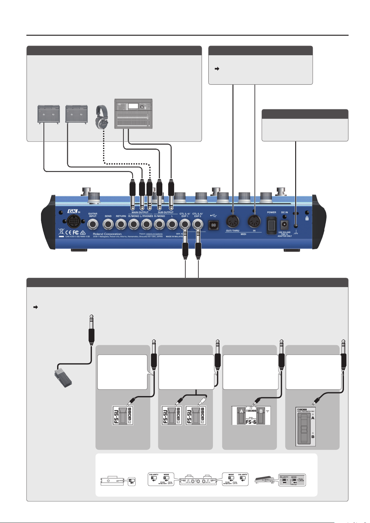
Getting Ready
MAIN OUTPUT jack / SUB OUTPUT jack
Connect these jacks to your guitar amp, headphones (sold separately), or to
PA (LINE).
* Connect your headphones to the MAIN OUTPUT L/PHONES jack.
* If your system is mono, use only the R/MONO jack.
* If you’re using headphones, don’t connect anything to R/MONO jack.
MIDI IN, MIDI OUT/THRU jacks
Connect an external MIDI device here.
For details, refer to “Reference Manual”
(PDF).
Ground Terminal
Connect this to an external earth or
ground if necessary.
CTL 3, 4/EXP 1, CTL 5, 6/EXP 2 jacks
You can connect an expression pedal (EV-30, FV-500L, FV-500H, or EV-5: sold separately) or footswitch (FS-5U, FS-6, FS-7: sold separately), and
use it to control various functions.
For details on the settings, refer to “Reference Manual” (PDF).
To use these as EXP 1,
EXP 2 jacks
Connect an expression
pedal.
* Use only the
specied expression
pedal (EV-30, FV500L, FV-500H, or EV5: sold separately).
By connecting any
other expression
pedals, you risk
causing malfunction
and/or damage to
the unit.
To use these as CTL 3,4 or CTL 5,6 jacks
Connect a footswitch.
FS-5U x 1 FS-5U x 2 FS-7FS-6
1/4” phone type
.
/
1/4” phone type
CTL 3
CTL 5
MODE / POLARITY switch
FS-5U FS-6 FS-7
Stereo 1/4” phone type
.
/
1/4” phone type x 2
CTL 4
CTL 6
CTL 3
CTL 5
Stereo 1/4” phone type
.
/
Stereo 1/4” phone type
CTL 4
CTL 6
CTL 3
CTL 5
Stereo 1/4” phone type
.
/
Stereo 1/4” phone type
CTL 4
CTL 6
CTL 3
CTL 5
5
Page 6
Getting Ready
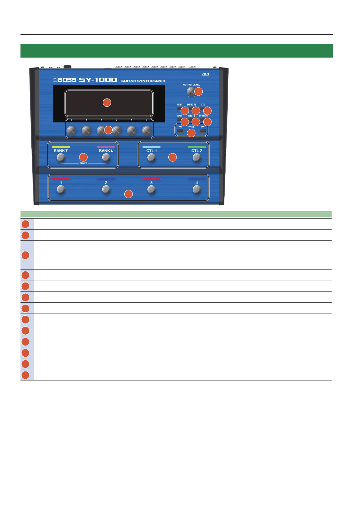
Panel Descriptions
11 12
3
1
4 5 6
7 8 9
2
10
13
No. Name Explanation Page
Display Various information regarding the SY-1000 is indicated here. p. 11
1
[1]–[6] knobs Use this to select or edit the value of the parameter that’s shown in the display. p. 12
2
This adjusts the volume level for the MAIN OUTPUT jack.
[OUTPUT LEVEL] knob
3
[INST] button Species the sound of the INST (sound engine). p. 14
4
[EFFECTS] button Species the eect settings and the order in which eects are connected. p. 16
5
[CTL] button Accesses the CTL screen, where you can assign functions to the buttons and switches. p. 18
6
[EXIT] button Used to return previous screens and to undo operations. –
7
[WRITE] button Use for storing settings in patches and executing operations. p. 19
8
[SYSTEM] button Used for making settings related to the SY-1000’s operating p. 20
9
[K] [J] (PAGE) buttons
10
BANK [I], BANK [H] switches
11
[CTL 1] [CTL 2] switches By default, the [CTL 1] and [CTL 2] pedals control a function that’s assigned by each patch. –
12
[1]–[4] switches Switch patches. –
13
* Depending on how you switch the settings, you can also adjust the MAIN OUTPUT and
SUB OUTPUT volumes simultaneously.
[SYSTEM] button0HARDWARE SETTING0KNOB0OUTPUT LEVEL KNOB
This switches the screens displayed in the display. p. 11
Switch banks. p. 13
–
6
Page 7
Getting Ready
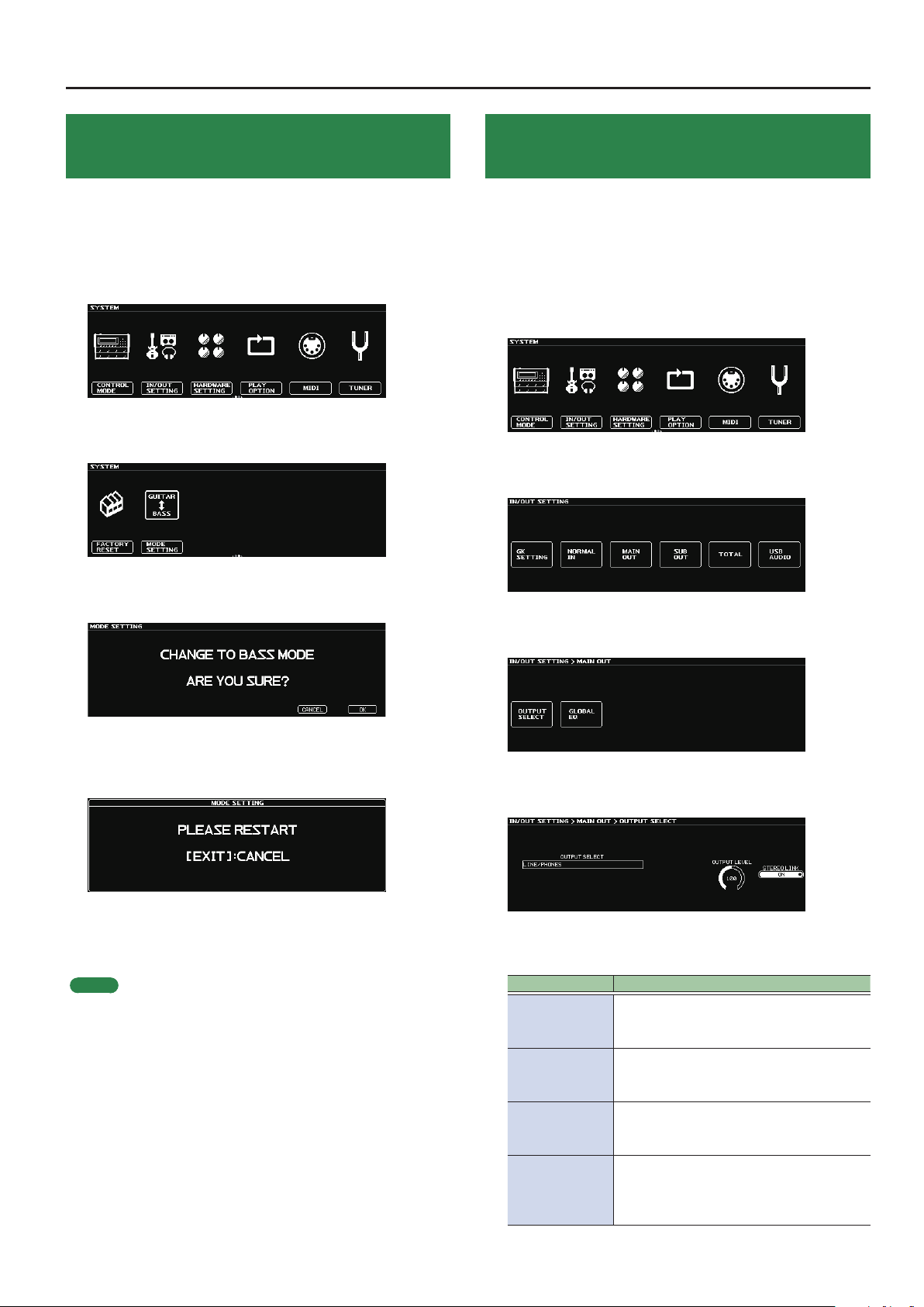
Selecting the Instrument (Guitar/Bass) to Use (MODE SETTING)
Here you can select whether you’re connecting a guitar or a bass to
the SY-1000.
Choose guitar mode (GUITAR) if you’re using a guitar, or choose bass
mode (BASS) if you’re using a bass.
1. Press the [SYSTEM] button.
2. Use the [K] [J] (PAGE) buttons to access the “MODE
SETTING” icon.
Specifying the Device Connected to OUTPUT Jacks (OUTPUT SELECT)
Use this procedure to set the type of device connected to the output
jacks (MAIN OUT, SUB OUT).
This applies the optimal adjustments for the device that is connected.
1. Press the [SYSTEM] button.
2. Use the [K] [J] (PAGE) buttons to access the “IN/
OUT SETTING” icon.
3. Press the [2] knob.
The IN/OUT SETTING screen appears.
3. Press the [2] knob.
The message appears.
4. To change the mode, press the [6] knob.
If you decide to cancel, press the [5] knob. When you press the [6]
knob, a message appears.
5. Turn the power of the SY-1000 o, then on again.
If you decide to cancel, press the [EXIT] button. Verify that the
SY-1000 has started with the mode that you specied.
MEMO
5 With the factory settings, this is set to “GUITAR.”
5 The SY-1000 starts with the specied mode until the next time
you change the mode.
5 Some parameters are displayed dierently depending on the
selected mode.
5 Patches are saved separately for guitar mode and bass mode.
4. Press the [3] knob or [4] knob.
The MAIN OUT screen or SUB OUT screen appears.
5. Press the [1] knob.
The OUTPUT SELECT screen appears.
6. Turn the [1] knob.
Select the connected device (type of amp).
OUTPUT SELECT Explanation
Choose this setting if you’re using
LINE/PHONES
JC-120 RETURN
JC-120 INPUT
COMBO AMP 1
RETURN
headphones, or if the SY-1000 is connected
to a keyboard amp, mixer, or digital recorder.
Choose this setting if the SY-1000 is
connected to the RETURN jack of the Roland
JC-120 guitar amp.
Choose this setting if the SY-1000 is
connected to the guitar input jack of a JC120 guitar amp.
Choose this setting if the SY-1000 is
connected to the RETURN jack of a combo
type amp (with amp and speaker in a single
unit) equipped with one speaker.
7
Page 8
Getting Ready
OUTPUT SELECT Explanation
Choose this setting if the SY-1000 is
COMBO AMP 1
INPUT
COMBO AMP 2
RETURN
COMBO AMP 2
INPUT
STACK AMP
RETURN
STACK AMP
INPUT
BASS AMP WITH
TWEETER
BASS AMP NO
TWEETER
connected to the guitar input jack of a
combo type amp (with amp and speaker in a
single unit) equipped with one speaker.
Choose this setting if the SY-1000 is
connected to the RETURN jack of a combo
type amp (with amp and speaker in a single
unit) equipped with two speakers.
Choose this setting if the SY-1000 is
connected to the guitar input jack of a
combo type amp (with amp and speaker in a
single unit) equipped with two speakers.
Set this when connecting to the RETURN jack
on a stack-type amp.
Set this when connecting to the guitar input
jack on a stack-type amp.
Use this setting when connecting to a
tweeter-equipped bass amp.
Use this setting when connecting to a bass
amp that has no tweeter. The high-frequency
range is adjusted.
7. Press the [EXIT] button.
You’ll be returned to the Play screen.
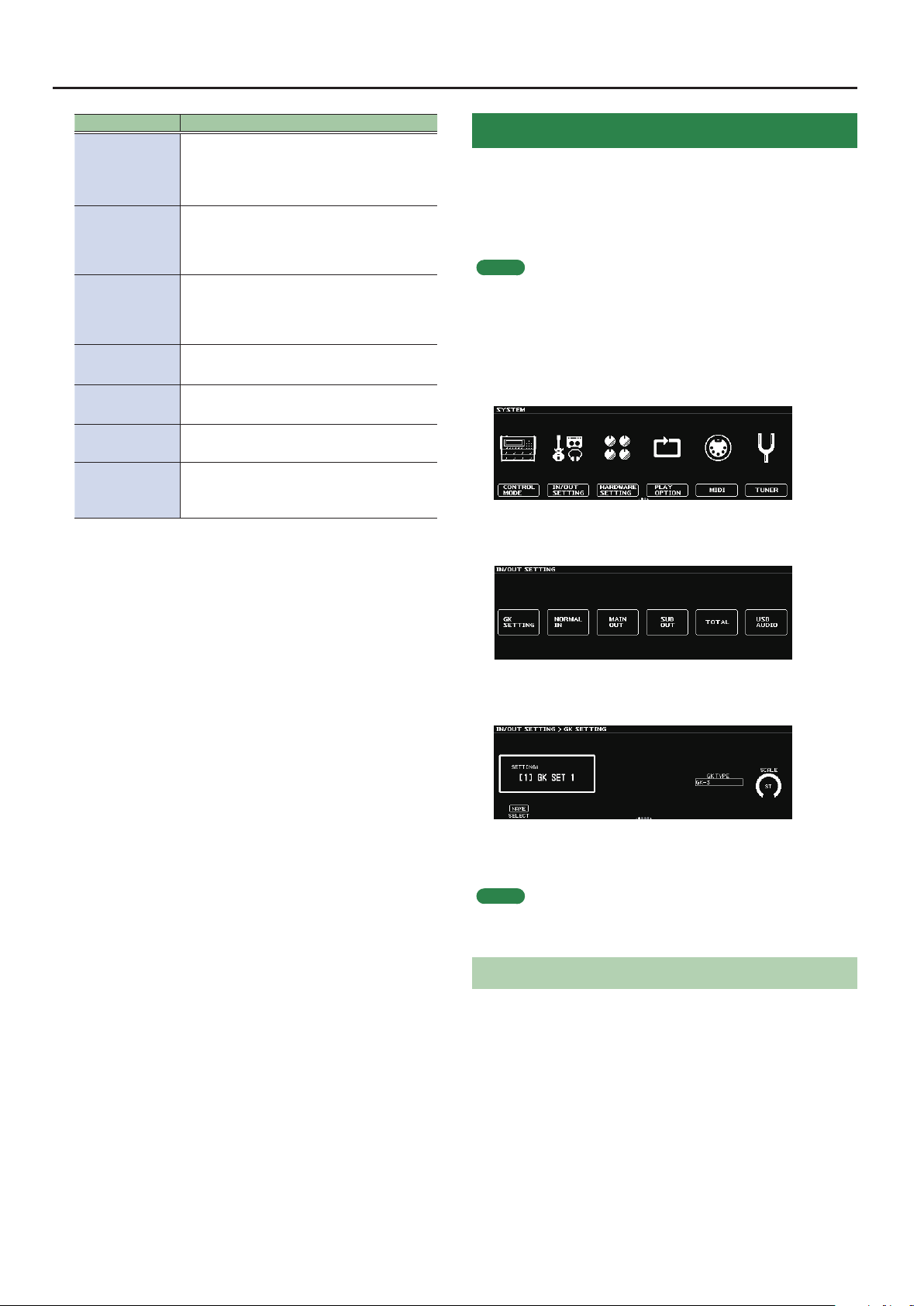
Making Pickup Settings (GK SETTING)
Make settings for the divided pickup in order to ensure that you’ll
always be playing the SY-1000 in the optimal state.
The SY-1000 can save ten types of these settings (GK SETTING).
Here we explain the example of saving pickup settings in SETTING:
[1].
MEMO
The GK SETTING is saved even when the power is turned o. You
don’t need to make this setting again each time you perform.
1. Press the [SYSTEM] button.
2. Use the [K] [J] (PAGE) buttons to access the “IN/
OUT SETTING” icon.
3. Press the [2] knob.
The IN/OUT SETTING screen appears.
4. Press the [1] knob.
The GK SETTING screen appears.
5. Turn the [1] knob to select SETTING: [1].
The pickup settings will be saved in SETTING: [1].
MEMO
Pickup settings are automatically saved in the number (SETTING: [1]–
[10]) that you selected in step 5.
Specifying the Pickup Type
Choose the type of pickup that’s installed on your guitar (bass).
6. If using guitar mode, turn the [5] knob.
If using bass mode, turn the [4] knob.
8
Page 9
Getting Ready
GK PU TYPE
(GUITAR MODE)
Explanation
GK-3 Choose this if you’re using a Roland GK-3.
Choose this if you’re using a Roland GK-2A,
GK-2A
or if you’re using a (commercially available)
guitar with a built-in divided pickup.
GC-1
PIEZO
Choose this if you’re using a Roland V-Guitar
GC-1.
(at response)
PIEZO F Fishman
PIEZO G Graph Tech
Piezo
Pickup
PIEZO L L.R. Baggs
PIEZO R RMC
GK PU TYPE
(BASS MODE)
Explanation
GK-3B Choose this if you’re using a GK-3.
Choose this if you’re using a Roland GK-2B, or
GK-2B
if you’re using a (commercially available) bass
with a built-in divided pickup.
PIEZO
PIEZO G Graph Tech
Piezo
Pickup
(at response)
PIEZO R RMC
7. If using guitar mode, turn the [6] knob.
If using bass mode, turn the [5] knob.
Specify the length that is correct for your guitar (bass).
If you’re using GUITAR MODE, choose “ST (648mm)” for a standard
Stratocaster type, or choose “LP (628mm)” for a Les Paul type.
If you’re using BASS MODE, For a standard Jazz Bass type or
Precision Bass type, choose LONG JB/PB (864 mm).
MEMO
This parameter is not shown if GK PU TYPE is set to “Roland V-Guitar
GC-1.”
Specifying the Pickup Position (Bass Mode Only)
Specify the position of the divided pickup that’s installed on your
bass.
MEMO
If you’ve installed a divided pickup on your guitar, proceed to step 9
“Specifying the Distance from the Bridge” (p. 10) (this step is not
needed).
8. Turn the [6] knob
Specify the GK PU POSITION according to the position of the
divided pickup that’s installed.
MEMO
5 A piezo pickup is a type of pickup that is mounted on the bridge
of the guitar, and uses a piezoelectric element to detect the
vibrations of the strings.
5 If you don’t know the type of your piezo pickup, try selecting
dierent choices while you play your guitar, and choose the
setting that produces the most natural sound.
5 If you’ve chosen piezo type, you’ll be able to make further
adjustments to the tone quality of the high range and low range.
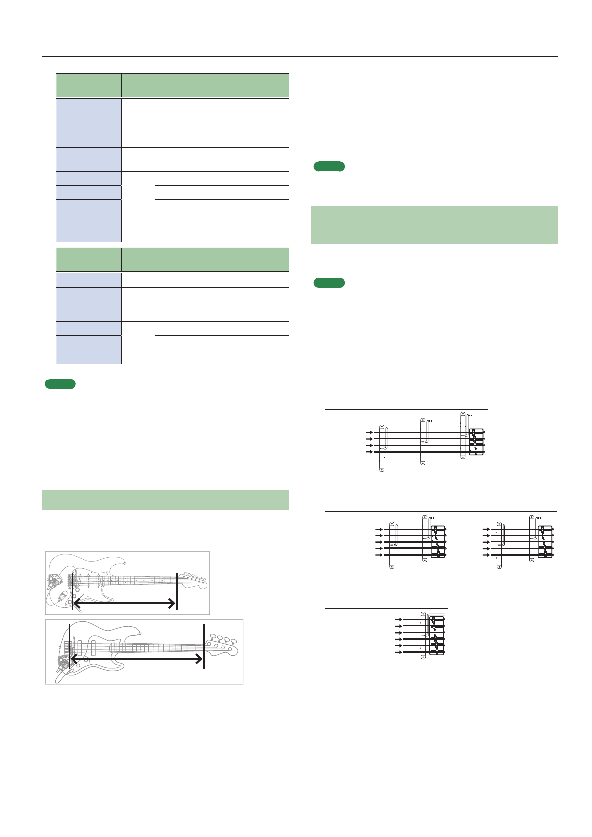
Specifying Your Guitar’s (Bass’s) Scale Length
Specify your guitar’s (bass’s) scale length (the distance from the
bridge to the nut).
Guitar
For a 4-string bass
GK PU
POSITION
1st string
2nd string
3rd string
4th string
For a 5-string bass
GK PU
POSITION
1st string
2nd string
3rd string
4th string
Low B string
For a 6-string bass
GK PU
POSITION
High C string
4STR-1
5STR-Lo1
1st string
2nd string
3rd string
4th string
Low B string
4STR-2 4STR-3
High C
1st string
2nd string
3rd string
4th string
6STR
5STR-Hi15STR-Lo2 5STR-Hi2
string
Bass
9
Page 10
Getting Ready
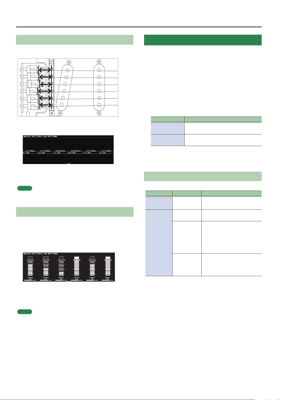
Specifying the Distance from the Bridge
For each string, specify the distance from the bridge to the center of
the pickup.
9. Use the [K] [J] (PAGE) buttons to access the
DISTANCE screen.
10.
Turn the [1]–[6] knobs.
Specify the distance from the bridge to the center of the pickup.
MEMO
This setting is not needed if GK PU TYPE is “Roland V-Guitar GC-1” or if
you selected a piezo type pickup.
Adjusting the Pickup Sensitivity
The volume will dier if the distances between each string and the
divided pickup are dierent. Specify the sensitivity of the pickup to
compensate for this volume dierence.
11.
Use the [K] [J] (PAGE) buttons to access the SENS
screen.
Tuning the Guitar (TUNER)
Tune the guitar (bass).
The SY-1000 is equipped with a conventional monophonic tuner
which lets you tune your instrument one string at a time (SINGLE
MODE), and a polyphonic tuner which lets you play and tune all of
your open strings simultaneously (MULTI MODE).
1. Press the BANK [I] switch and BANK [H] switch
simultaneously.
The TUNER screen appears.
2. Use the [K] [J] (PAGE) buttons to select the tuner
mode.
TUNER MODE Explanation
MULTI MODE
SINGLE MODE
3. Play an open string, and tune it so that only the
center indicator in the screen is lit.
Making Tuner Settings
These settings specify how the tuner operates.
Parameter Value Explanation
PITCH
OUTPUT
You can play and tune six strings
simultaneously
You can play one individual string to tune
that string.
435–445Hz
(default: 440Hz)
MUTE
BYPASS
THRU
Species the reference pitch.
Sound will not be output while
tuning.
While tuning, the sound from
the GK IN connector/GUITAR
INPUT jack will be output without
change.
All modelings and eects will be
o.
Allows you to tune while hearing
the current eect/modeling
sound.
* Only for single mode.
12.
While playing the strings strongly, turn the [1]–[6]
knobs so that the level meters reach the triangular
marks.
MEMO
Depending on the guitar (bass) you’re using, the level meter
might reach full-scale even if the sensitivity is at minimum. If this
is the case, adjust the distance between the divided pickup and
the string so it’s somewhat greater than the recommendation.
10
Page 11
Basic Operation
Here we explain how you can use the buttons and knobs to operate
the SY-1000, and how to switch screens.
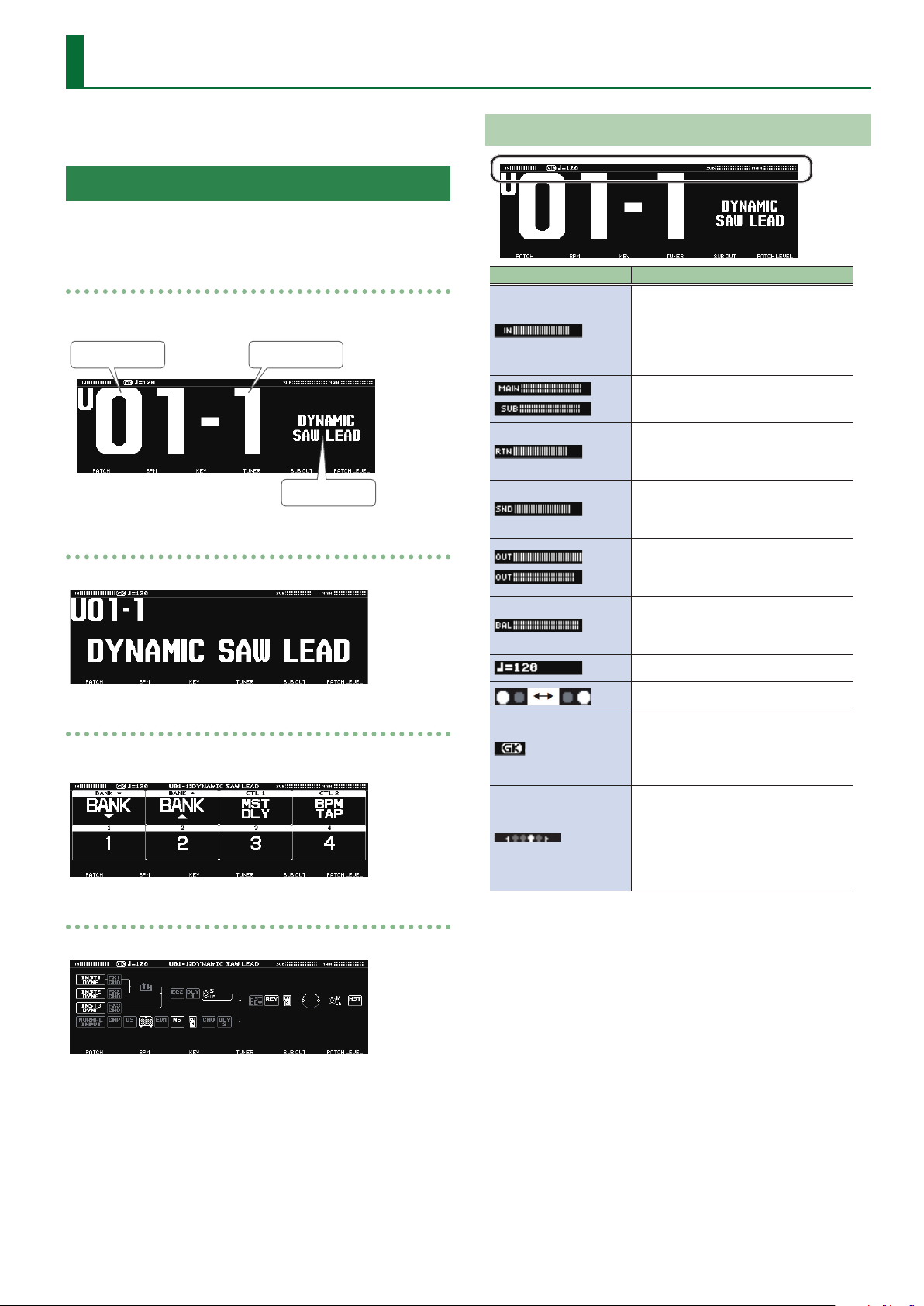
Display (Play Screen)
The screen that appears after you start the SY-1000 is called the “play
screen.”
Screen 1
This screen shows the bank number and patch number in especially
large characters.
Bank number
Screen 2
This screen shows the bank number, patch number, and patch name.
Patch number
Patch name
About the Icons
Icon Explanations
Indicates the input level of the GK IN
connector.
* When using a normal patch (p. 13),
this indicates the level of the guitar
signal.
Indicates the output level of the MAIN
OUTPUT jacks and SUB OUTPUT jacks.
Indicates the input level of the
RETURN jack.
* Shown in the EFFECTS edit screen.
Indicates the output level of the SEND
jack.
* Shown in the EFFECTS edit screen.
Indicates the output level of the
selected eect block.
* Shown in the EFFECTS edit screen.
Indicates BALANCER1–3 and MIXER
BALANCE.
* Shown in the EFFECTS edit screen.
Indicates the BPM.
Screen 3
This screen shows the functions that are assigned to the pedal
switches of the unit.
Screen 4
This screen shows how the INST and eects are connected (CHAIN).
Blinks in time with the BPM.
Shown when a GK patch (p. 13) is
selected.
When using a normal patch (p. 13),
this icon goes dark.
When the screen contains multiple
pages, this indicates the position of
the current page.
Indicates the page to which you
navigate using the [K] [J] (PAGE)
buttons (edit screen).
11
Page 12
Basic Operation
Screen Operations
In the play screen, you can turn or press the [1]–[6] knobs to adjust
the parameters that are shown in the lower part of the display.
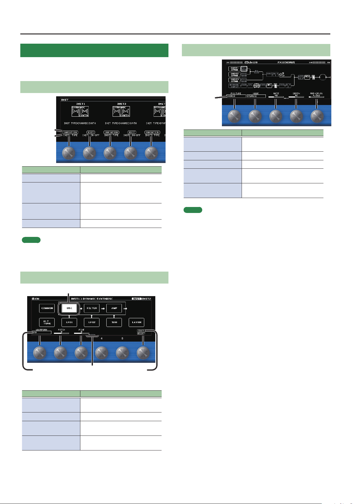
Operating Example 1 (INST Screen)
Press operation
Turn operation
Operation Explanation
Turn the [1] knob Changes the INST TYPE of INST1.
Accesses a screen where you can
Press the [1] knob
Turn the [2] knob
Press the [2] knob Accesses the edit screen for INST1.
switch the INST TYPE variation of
INST1.
Turns INST1 on/o.
When o, the icon is shown in gray.
Operating Example 3 (EFFECT Edit Screen)
Turn operation
Operation Explanation
Turn the [1]–[5] knobs
Turn the [6] knob Selects the block to edit.
Press the [6] knob Turns the selected block on/o.
Long-press the [6] knob
Turn the [6] knob while
pressing it
MEMO
To change a value in larger steps, turn a [1]–[5] knob while pressing it.
Changes the value of the setting for
the parameter
Shows a list with all parameters of
the selected block.
Changes the position of the selected
block.
MEMO
As for INST1, you can operate INST2 with the [3] knob and [4] knob,
and operate INST3 with the [5] knob and [6] knob.
Operating Example 2 (INST Edit Screen)
Use the [6] knob to select
Turn operation
Operation Explanation
Turn the [1]–[5] knobs
Turn the [6] knob Selects the block to edit.
Press the [6] knob
Press the [K] [J] (PAGE)
buttons
Use the PAGE [K] [J]
buttons to switch
Changes the value of the setting for
the parameter
Shows a list with all parameters of
the selected block.
Switches the parameters to show.
Press operation
12
Page 13
Switching Patches (Tone)
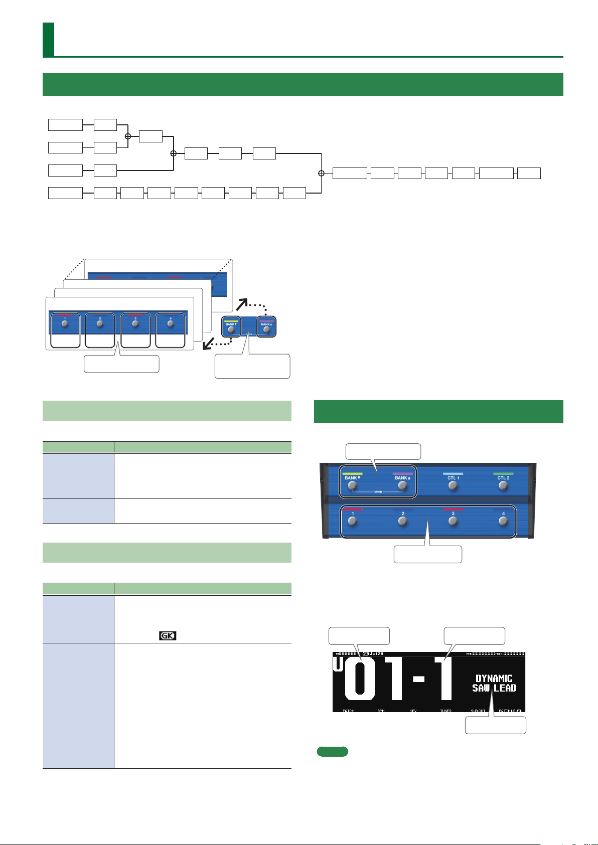
The Structure and Patches of the SY-1000
The SY-1000 consists of three sound engines (the INST blocks) and eects whose connections you are free to change (the FX block).
INST1
INST2
FX1
FX2
S/R
EQ2 DLY1 SUB L/R
INST3
NORMAL
The INST settings together with the combination of eects are collectively called a “patch.”
A set of four patches is called a “bank.”
Patches are managed by their bank (1–50) and number (1–4); the SY-1000 can store 200 patches.
Bank 3
Bank 2
Bank 1
Patch 1 Patch 3
Types of Bank
The SY-1000 has two types of bank.
Types of bank Explanation
Preset bank
(P01–P50)
User bank (U01–
U50)
FX3
CMP DS AMP EQ1 NS FV1 DLY2
Bank 50
Patch 2 Patch 4
[1]–[4] switch
Cannot be overwritten, however, you can write
a patch into the User bank, modify the settings
to your needs and store your modied version in
the User bank.
Can be overwritten.
BANK [I], BANK [H]
CHO
switch
MST DLY REV FV2 DIV MIX MAIN L/R MST
Selecting a Patch
When you switch patches, the tonal character changes.
BANK [I] [H] switches
Types of Patch
The SY-1000 has two types of patch.
Types of patch Explanation
Patches for a guitar (bass) that uses a divided
GK patch
Normal patch
pickup.
If these patches are selected, the display shows
the GK icon
Patches for a conventional guitar (bass) that is
connected to the GUITAR INPUT. These can be
used even if you don’t have a divided pickup.
You can also use these patches with the
conventional guitar (bass) signal (normal
pickup) that is routed through the divided
pickup.
If you’re using Normal patch, the GK icon goes
dark.
* DYNAMIC SYNTH is the only INST TYPE that
can be selected for normal patches.
[1]–[4] switches
1. Use the BANK [I] [H] switches to select a bank.
2. Use the [1]–[4] switches to select a patch within the
selected bank.
.
Bank number
MEMO
You can also change patches by turning [1] knob below the
display.
Patch number
Patch name
13
Page 14
Editing a Patch
Here’s how to create a patch by editing the parameters of the INST
blocks and the eect block, and combining them.
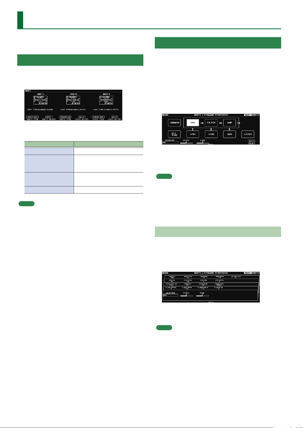
Changing the INST
Editing the INST
You can edit each INST in detail.
Here we explain using the example of the DYNAMIC SYNTH screen of
INST1.
1. Press the [INST] button.
The INST screen appears.
2. Turn the [1]–[6] knobs.
The INST screen shows the INST TYPE for INST1–INST3.
Operation Explanation
Turn the [1] knob Changes the INST TYPE of INST1.
Accesses a screen where you can
Press the [1] knob
Turn the [2] knob
Press the [2] knob Accesses the edit screen for INST1.
MEMO
As for INST1, you can operate INST2 with the [3] knob and [4]
knob, and operate INST3 with the [5] knob and [6] knob.
switch the INST TYPE variation of
INST1.
Turns INST1 on/o.
When o, the icon is shown in gray.
1. In the INST screen, press the [2] knob.
The INST1 screen appears.
* The pages diers depending on the INST TYPE.
2. Turn the [6] knob to select the block that you want
to edit.
The selected block is shown in white.
3. Turn the [1]–[5] knobs to edit the setting of the
parameter.
MEMO
5 To change a value in larger steps, turn a knob while pressing it.
5 You can use the PAGE [K] [J] buttons to switch between the
parameters.
5 The number of parameters and pages diers depending on the
eect.
5 In the edit screen, you can press the [INST] button to switch to the
edit screen of another INST.
Viewing All Parameters While You Edit
You can also edit while viewing a list of all parameters for the
selected block.
1. In the edit screen, press the [6] knob.
Shows a list with all parameters of the selected block.
2. Turn the [1]–[6] knobs to edit the setting of the
parameter.
MEMO
You can use the PAGE [K] [J] buttons to switch between the
parameters.
14
Page 15
Editing a Patch
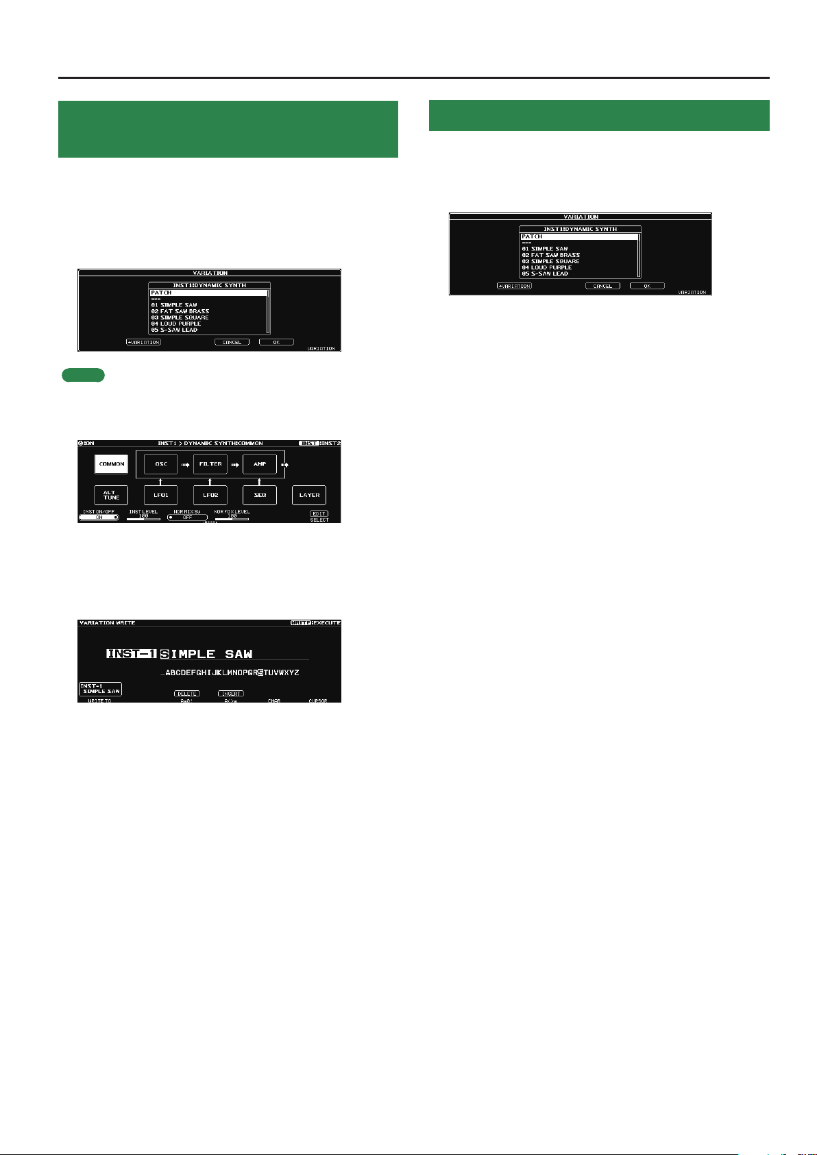
Saving the Edited INST Settings (VARIATION)
Your preferred settings for each instrument can be saved as a
“VARIATION.” Since a variation can also be used from another patch, it
is convenient for sound design.
1. In the INST screen, press the [1] knob.
The VARIATION screen appears.
MEMO
From the INST edit screen, you can also access the variation screen
using the following methods.
1. In the edit screen, select the “COMMON” block.
Recalled a Saved INST Variation
1. In the INST screen, press any one of the knobs [1]
(INST1), [3] (INST2), or [5] (INST3).
The VARIATION screen appears.
2. Turn the [6] knob to select a variation.
You can also audition the sound while selecting a variation.
3. Press the [5] knob to recall the selected variation.
2. Use the PAGE [J] buttons to move to the last page.
3. Press the [5] knob.
4. Press the [2] knob.
The VARIATION WRITE screen appears.
5. Turn the [1] knob to select the save-destination
number.
6. Use the [3]–[6] knobs to specify the variation name.
7. Press the [WRITE] button.
The variation is saved.
To cancel this procedure, press the [4] knob.
15
Page 16
Editing a Patch
Editing the Eects
You can edit the eect settings, and change the order of blocks such
as output and send/return (the eect chain).
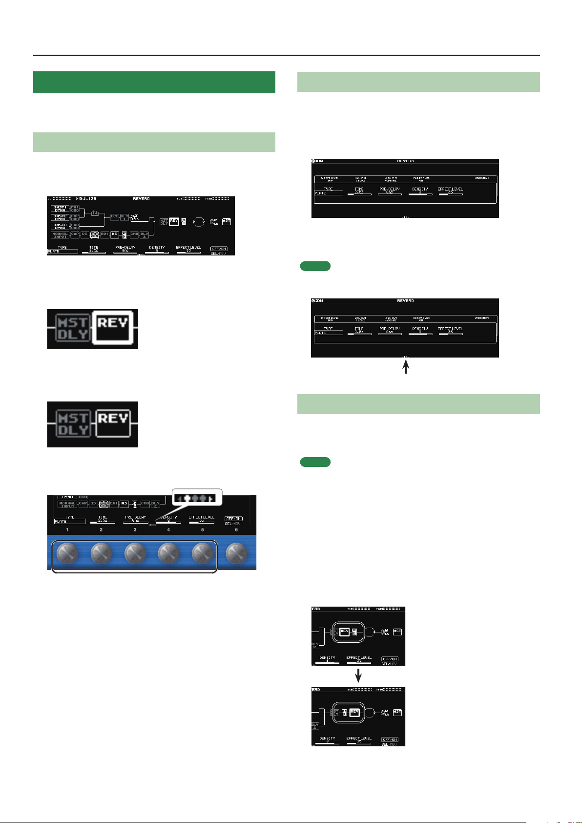
Basic Operation for Eect Editing
1. Press the [EFFECT] button.
The edit screen (eect chain) appears.
2. Turn the [6] knob to select the block that you want
to edit.
The selected block is enclosed by a thick frame.
* By pressing the [6] knob you can turn the selected eect on/o.
Eects that are o are shown in gray. When the eect is turned on,
it is shown in white.
O On
Editing While Viewing All Parameters
You can also edit while viewing a list of all parameters for the
selected block.
1. In the edit screen, long-press the [6] knob.
Shows a list with all parameters of the selected block.
2. Turn the [1]–[6] knobs to edit the parameter
settings.
MEMO
You can use the PAGE [K] [J] buttons to switch between the
parameters.
Use the PAGE [K] [J]
buttons to switch
Changing the Eect Order
3. Use knobs [1]–[5] to adjust the parameters that are
shown below the screen.
Use the PAGE [K] [J] buttons to switch between the parameters
that you want to edit. The current page is indicated in the lower
center of the screen.
* To change a value in larger steps, turn a knob while pressing it.
* The number of parameters and pages diers depending on the
eect.
By moving blocks such as eects, output, and send/return, you can
freely change the order in which the eects are placed, or arrange
them in parallel.
MEMO
5 You can change the order of the INST1–3 blocks and the NORMAL
block.
5 The MST (MASTER) block cannot be moved.
1. Press the [EFFECT] button.
The eect chain is shown.
2. Use the [6] knob to select the block that you want
to move.
3. While pressing the [6] knob, turn it left or right.
The selected block moves left or right.
16
Page 17
Editing a Patch
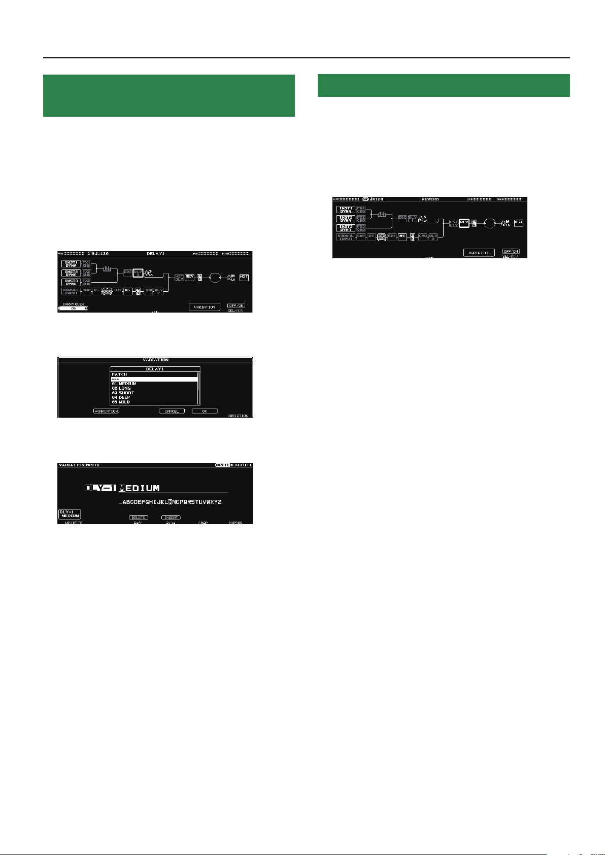
Saving the Edited Eect Settings
(VARIATION)
Your preferred settings for each eect can be saved as a “VARIATION.”
Since a variation can also be used from another patch, it is
convenient for sound design.
1. Press the [EFFECT] button.
2. Use the [6] knob to choose the eect you’re going
to edit.
3. Use the PAGE [K] [J] buttons to move to the last
page.
4. Press the [5] knob.
The VARIATION screen appears.
Recalled a Saved Eect Variation
1. Press the [EFFECT] button.
2. Use the [6] knob to choose the eect you’re going
to edit.
3. Use the PAGE [K] [J] buttons to move to the last
page.
4. Press the [5] knob.
The VARIATION screen appears.
5. Turn the [6] knob to select a variation.
You can also audition the sound while selecting a variation.
6. Press the [5] knob to recall the selected variation.
5. Press the [2] knob.
The VARIATION WRITE screen appears.
6. Turn the [1] knob to select the save-destination
number.
7. Use knobs [3]–[6] to name the VARIATION.
8. Press the [WRITE] button.
The variation is saved.
To cancel this procedure, press the [4] knob.
17
Page 18
Editing a Patch
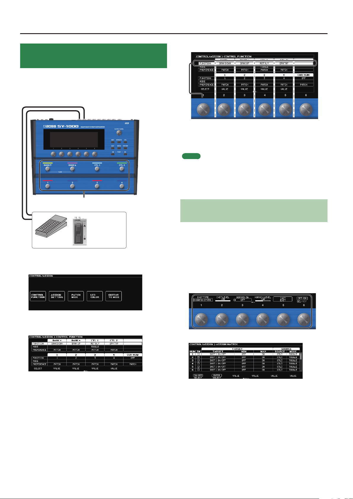
Assigning Functions to the Foot Switches and Expression Pedal
A variety of functions can be assigned to each of the top panel
footswitches, and expression pedals or footswitches that are
connected to the rear panel CTL3, 4/EXP1 jack and CTL5, 6/EXP2 jack
(p. 5).
Built-in footswitches
Turning the knob will move the selected item vertically.
The settings of the selected item can now be edited.
4. Turn knobs [2]–[6] to edit the value of the item
selected for each switch.
MEMO
5 You can use the PAGE [K] [J] buttons to switch between the
parameters.
5 The footswitch and expression pedal functions must be specied
for each patch; however, if you set PREFERENCE to SYSTEM, all
patches will use those functions in common.
Making Assignments from the Eect Edit
EXP1, EXP2
CTL3–CTL6
1. Press the [CTL] button.
The CONTROL/ASSIGN screen appears.
2. Press the [1] knob.
The CONTROL FUNCTION screen appears.
3. Turn the [1] knob to select the item that you want
to set.
Screen (Quick Assign)
In the eect edit screen (p. 16), you can select an eect parameter
and assign that parameter to the switch of your choice.
1. Press the [EFFECT] button.
2. Turn the [6] knob to select the block that you want
to edit.
3. Long-press the [1]–[5] knobs for the parameter that
you want to assign.
The ASSIGN MATRIX screen appears.
* You can also access the ASSIGN MATRIX screen in the same way
from the all-parameter list screen (p. 14). You can also access it
by selecting the [CTL] button0 “ASSIGN SET TING.”
18
4. Press the [1] knob to turn the SW on.
5. Turn knobs [2]–[6] to edit parameters.
If necessary, use the PAGE [K] [J] buttons to switch between
pages of settings.
Use SOURCE to specify the pedal or MIDI message that you will
operate.
Page 19
Saving a Patch
The INST settings and the combination of eects can be saved in a
patch, and recalled at any time.
If you select a dierent patch or turn o the power after editing the
settings, edited settings will be lost. If you want to keep the data, you
must save it.
1. Press the [WRITE] button.
2. Press the [1] knob to select “WRITE” (PATCH WRITE).
3. Use the [1] knob to select the save-destination
(U01-1–U50-4).
You can use knobs [3]–[6] to edit the name.
Editing a name
To edit the patch name, use the [6] knob to move the cursor
and use the [5] knob to change the character.
Operation Explanation
Turn the [3] knob Selects the type of characters
Press the [3] knob Delete one character (delete)
Turn the [4] knob Switch uppercase/lowercase
Press the [4] knob Insert one space (insert)
Turn the [5] knob Changes the character
Turn the [6] knob Moves the cursor
4. Press the [WRITE] button.
The patch is written.
To cancel this procedure, press the [4] knob.
19
Page 20
Settings for the Entire SY-1000 (System Parameters)
Settings for the SY-1000
Here you can make settings that are common to the entire SY-1000
(system parameters).
For details on each parameter, refer to “SY-1000 Reference Manual” (PDF).
1. Press the [SYSTEM] button.
MEMO
You can use the PAGE [K] [J] buttons to see additional items.
2. Press a [1]–[6] knob to select the item that you want
to edit.
A sub-menu appears.
Restoring the Factory Default Settings (Factory Reset)
Restoring the SY-1000’s settings to their original factory default
settings is referred to as “Factory Reset.”
Not only can you return all of the settings to the values in eect when
the SY-1000 was shipped from the factory, you can also specify the
items to be reset.
* When you execute “Factory Reset,” the settings you made will
be lost. Save the data you need to your computer using the
dedicated software.
1. Press the [SYSTEM] button.
2. Use the [K] [J] (PAGE) buttons to select “FACTORY
RESET.”
3. Choose the type of settings to be restored to the
factory default settings with knobs [1] and [6].
Knob Explanation
[1] Species FROM.
[6] Species TO.
3. Once again press a [1]–[6] knob to select the item
that you want to edit.
4. Use knobs [1]–[6] to select parameters or edit the
values.
MEMO
The method of selecting parameters and editing their value will
dier depending on the item.
Value Explanation
SYSTEM System parameter settings
U01-1–U50-4
VARIATION Settings for VARIATION
Settings for Patch Numbers
U01-1–U50-4
4. Press the [WRITE] button.
Press the [6] knob to execute the factory reset.
To cancel factory reset, press the [5] knob.
Once the Factory Reset is complete, you are returned to the Play
screen.
Turning O the Auto O Function
The SY-1000 can turn o its power automatically. The power will turn
o automatically when 10 hours have passed since you last played or
operated the unit. The display will show a message approximately 15
minutes before the power turns o.
With the factory settings, this function is turned “ON” (power-o in 10
hours). If you want to have the power remain on all the time, turn it
“OFF.”
1. Press the [SYSTEM] button.
20
2. Choose “HARDWARE SETTING” 0 “OTHER.”
3. Use the [1] knob to select “OFF.”
4. Press the [EXIT] button a number of times to return
to the play screen.
Page 21
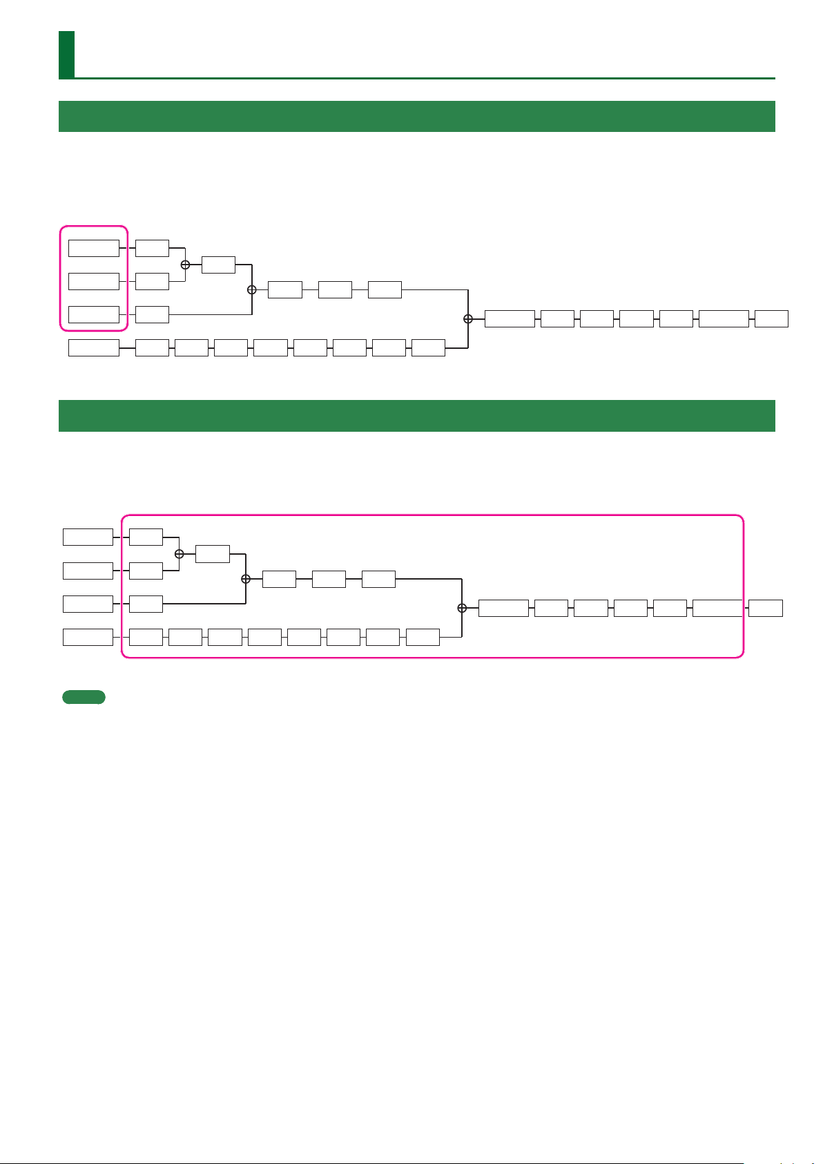
The Internal Structure of the SY-1000
INST (Instrument) Block
This is the sound engine section that generates sound based on the performance data from the divided pickup and the audio input from the
guitar (bass).
This can produce a variety of tones, synthesizers such as DYNAMIC SYNTH and the POLY FX which can apply eects independently to each string.
The SY-1000 lets you freely specify and combine three INST blocks.
INST1
INST2
INST3
NORMAL
FX1
S/R
FX2
FX3
CMP DS AMP EQ1 NS FV1 DLY2
EQ2 DLY1 SUB L/R
CHO
MST DLY REV FV2 DIV MIX MAIN L/R MST
EFFECT (Eects) Block
The SY-1000 is equipped with high-quality eects.
You can change the order in which the eects are connected.
You are also free to select the signals that are output from the MAIN OUTPUT jacks and the SUB OUTPUT jacks.
INST1
INST2
INST3
NORMAL
FX1
S/R
FX2
FX3
CMP DS AMP EQ1 NS FV1 DLY2
EQ2 DLY1 SUB L/R
CHO
MST DLY REV FV2 DIV MIX MAIN L/R MST
MEMO
5 In order to distinguish between the divided pickup and the conventional pickup installed on your guitar (bass), this manual uses the term
“normal pickup” when referring to the conventional pickup of your guitar (bass).
5 The sound of the normal pickup directly connected to the GUITAR INPUT jack or the sound of the normal pickup routed through the divided
pickup is input to the NORMAL block. You can mix this into the INST1–INST3 blocks.
21
Page 22
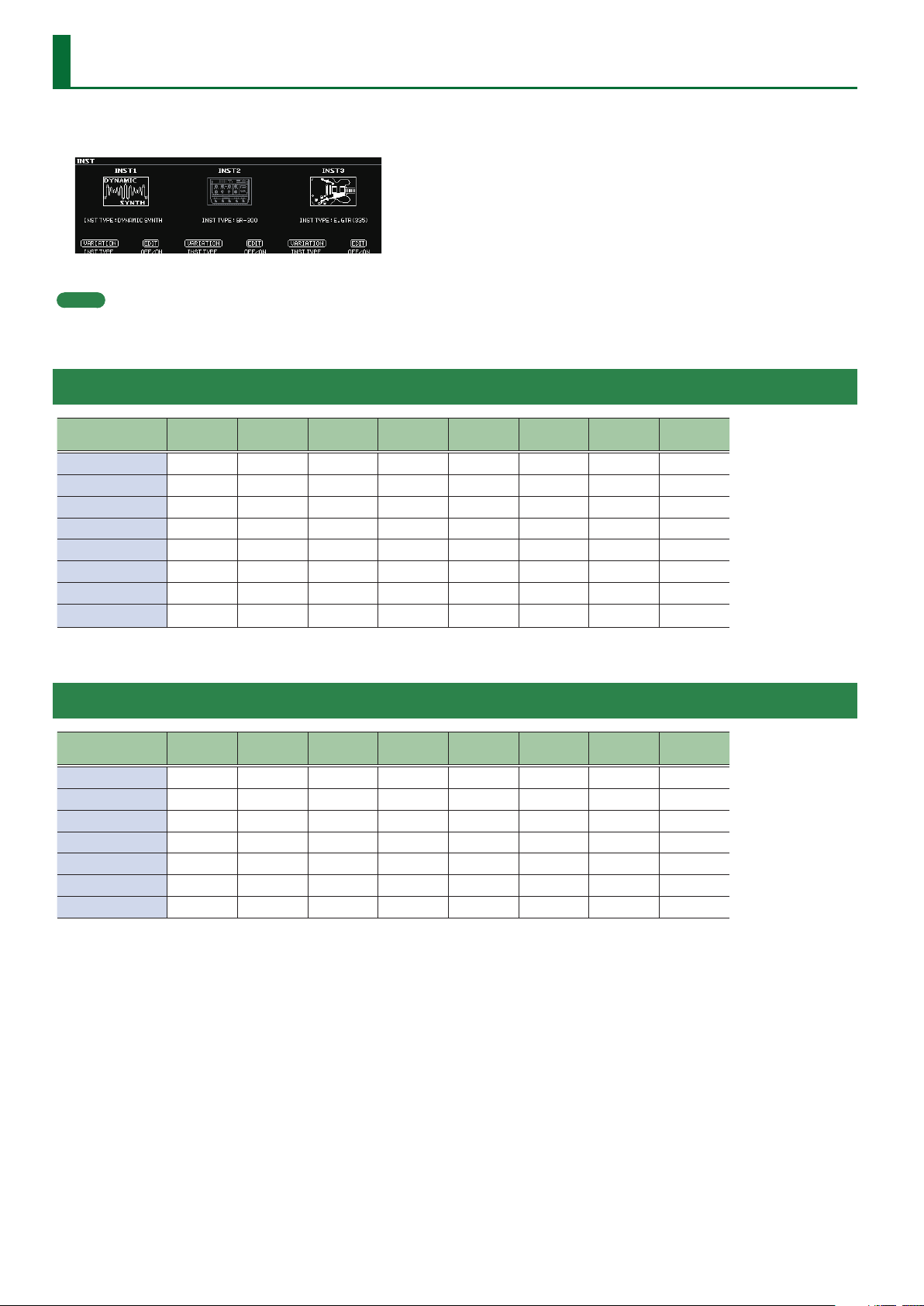
INST Parameters
1. Press the [INST] button.
The INST screen appears.
The INST screen shows the INST TYPE of INST1–INST3.
MEMO
5 The parameters shown depend on the type of instrument that you select.
5 INST1–INST3 are common parameters.
Availability of Functions for Each INST TYPE (GUITAR MODE)
INST TYPE ALT. TUNE 12STR STR BEND
DYNAMIC SYNTH
OSC SYNTH
GR-300
E.GUITAR
ACOUSTIC
E.BASS
VIO GUITAR
POLY FX
*1 If AMP Modeling is ON, the PAN eect disappears.
(
(
(
( ( ( ( ( *1 ( *1 ( (
( ( ( ( ( *1 ( *1 ( (
( ( ( ( ( *1 ( *1 ( (
(
(
–
–
–
–
–
( ( (
( ( (
( ( (
( ( (
( ( (
STRING
LEVEL
STRING
PAN
AMP
Modeling
– – –
– – –
– – –
–
–
Availability of Functions for Each INST TYPE (BASS MODE)
INST TYPE ALT. TUNE 12STR STR BEND STR LEVEL STR PAN
DYNAMIC SYNTH
OSC SYNTH
ANALOG GR
E.BASS
AC BASS
E.GUITAR
POLY FX
(
(
(
( ( ( ( ( *1 ( *1 ( (
( ( ( ( ( *1 ( *1 ( (
( ( ( ( ( *1 ( *1 ( (
(
–
–
–
–
( ( (
( ( (
( ( (
( ( (
AMP
Modeling
– – –
– – –
– – –
–
NS EQ
( (
(
NS EQ
(
–
–
*1 If AMP Modeling is ON, the PAN eect disappears.
22
Page 23
INST Parameters > INST TYPE
INST TYPE
Value Explanation
DYNAMIC
SYNTH
OSC SYNTH
GR-300
*2
ANALOG GR
*3
E.GUITAR
*1
ACOUSTIC
*1 *2
AC BASS
*1 *3
E.BASS
*1
VIO GUITAR
*2
POLY FX
This is a synthesizer that produces a sound
that responds to the natural nuances of your
performance.
This is a synthesizer that detects the pitch and attack
information in the input sound and outputs signals
produced by the built-in oscillator.
This models the Roland GR-300, the famed analog
polyphonic guitar synthesizer of yesteryear.
It provides hexa-distortion, with a hexa-VCO and
VCF (variable frequency lter) that generates
independent pitch-shiftable sawtooth waves for
the six strings, letting you enjoy analog synthesizer
sounds that reect the nuances of your guitar
performance.
This is the sound of a vintage analog polyphonic
bass synthesizer. It provides hexa-distortion, with
a hexa-VCO and VCF (variable frequency lter) that
generates independent pitch-shiftable sawtooth
waves for the six strings, letting you enjoy analog
synthesizer sounds that reect the nuances of your
bass performance.
This provides a variety of electric guitar sounds.
This provides a variety of acoustic guitar sounds.
This provides a variety of acoustic bass sounds.
This provides a variety of electric bass sounds.
By adding overtones (harmonics), this provides a
soft and distinctive tone.
This is an eect processor that independently
processes the signal of each string.
Parameter Value Explanation
STRING PAN 6–
STRING PAN 1
*2
STR PAN LowB
STR PAN 4th,
STR PAN 3rd,
STR PAN 2nd,
L50–CENTER–
R50
Species the left/right pan of
each string.
* The pan eect is canceled if a
monaural eect is connected
after the instrument.
STR PAN 1st,
STR PAN HiC
*3
You can save and load 50
variations for each TYPE.
(COMMON parameters and
ALT TUNE parameters are
VARIATION PATCH, 01–50
excepted.)
A saved VARIATION can be
loaded into a dierent patch,
which is convenient when
you’re creating sounds.
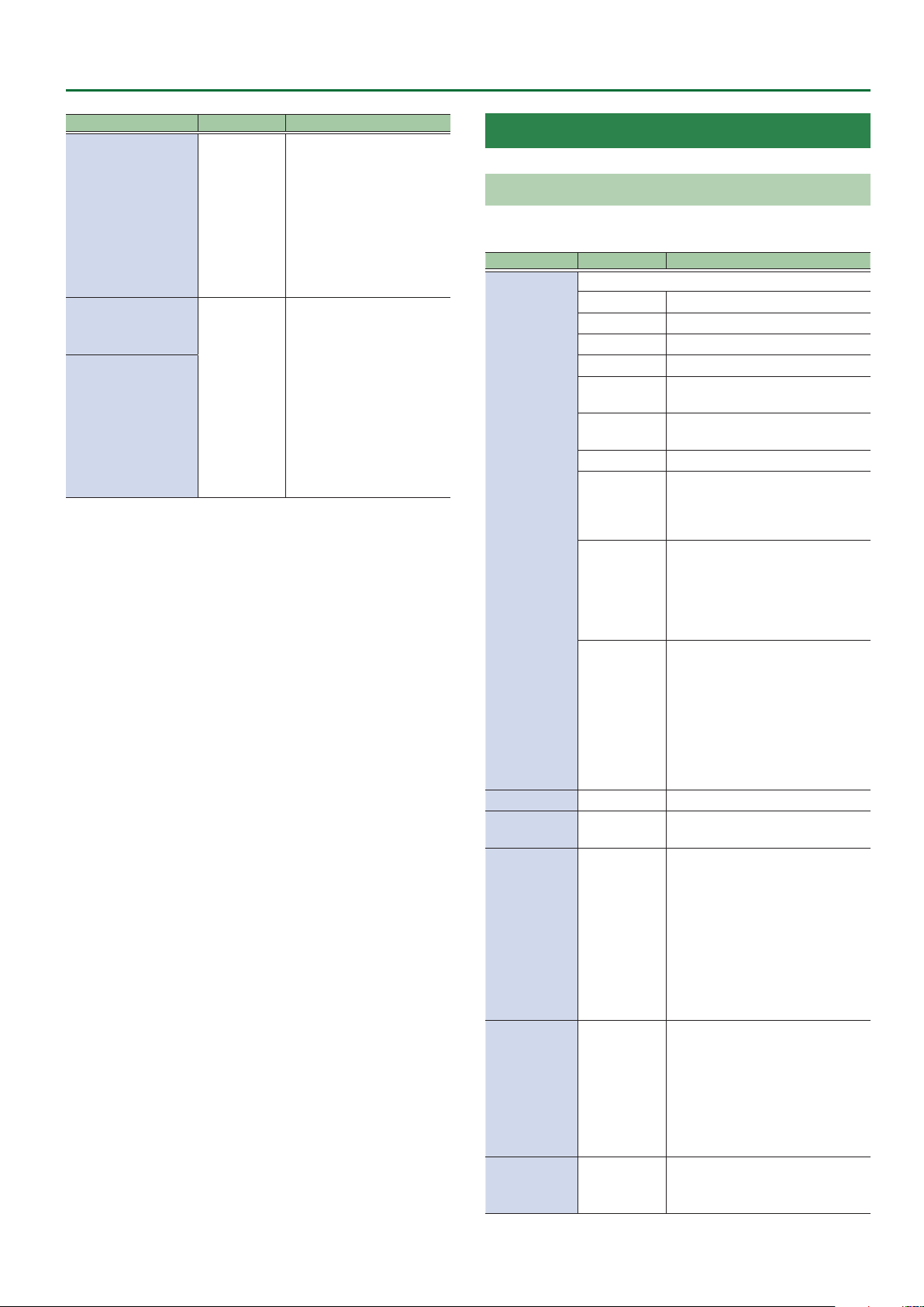
*1 If the INST TYPE is E.GUITAR, ACOUSTIC, AC BASS, or E.BASS,
the signal that passes through NOR MIX LEVEL is mixed directly
before AMP Modeling. Refer to “Signal ow for the NOR MIX
LEVEL parameter” (p. 23).
*2 Valid in the GUITAR MODE.
*3 Valid in the BASS MODE.
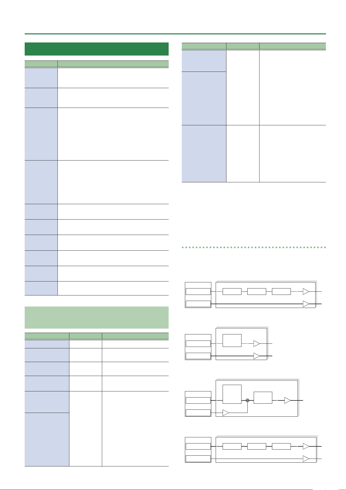
Signal ow for the NOR MIX LEVEL parameter
The ow of the signal that passes through the NOR MIX LEVEL
depends on the INST TYPE.
DYNAMIC SYNTH, OSC SYNTH
GK IN
Divided Pickup
Normal Pickup
INST
OSC FILTER AMP
INST LEVEL
NOR MIX LEVEL
Parameters Common to Each INST TYPE (COMMON)
Parameter Value Explanation
INST ON/OFF OFF, ON Instrument on/o
INST LEVEL 0–100
NOR MIX SW OFF, ON
NOR MIX SW
*1
0–200
STRING LEVEL6–
STRING LEVEL1
*2
STR LEVEL LowB
STR LEVEL 4th,
STR LEVEL 3rd,
0–100
STR LEVEL 2nd,
STR LEVEL 1st,
STR LEVEL HiC
*3
Species the volume of the
instrument.
Turns on/o the signal of the
normal pickup.
Adjusts the volume of the
normal pickup.
Species the output level of
each string.
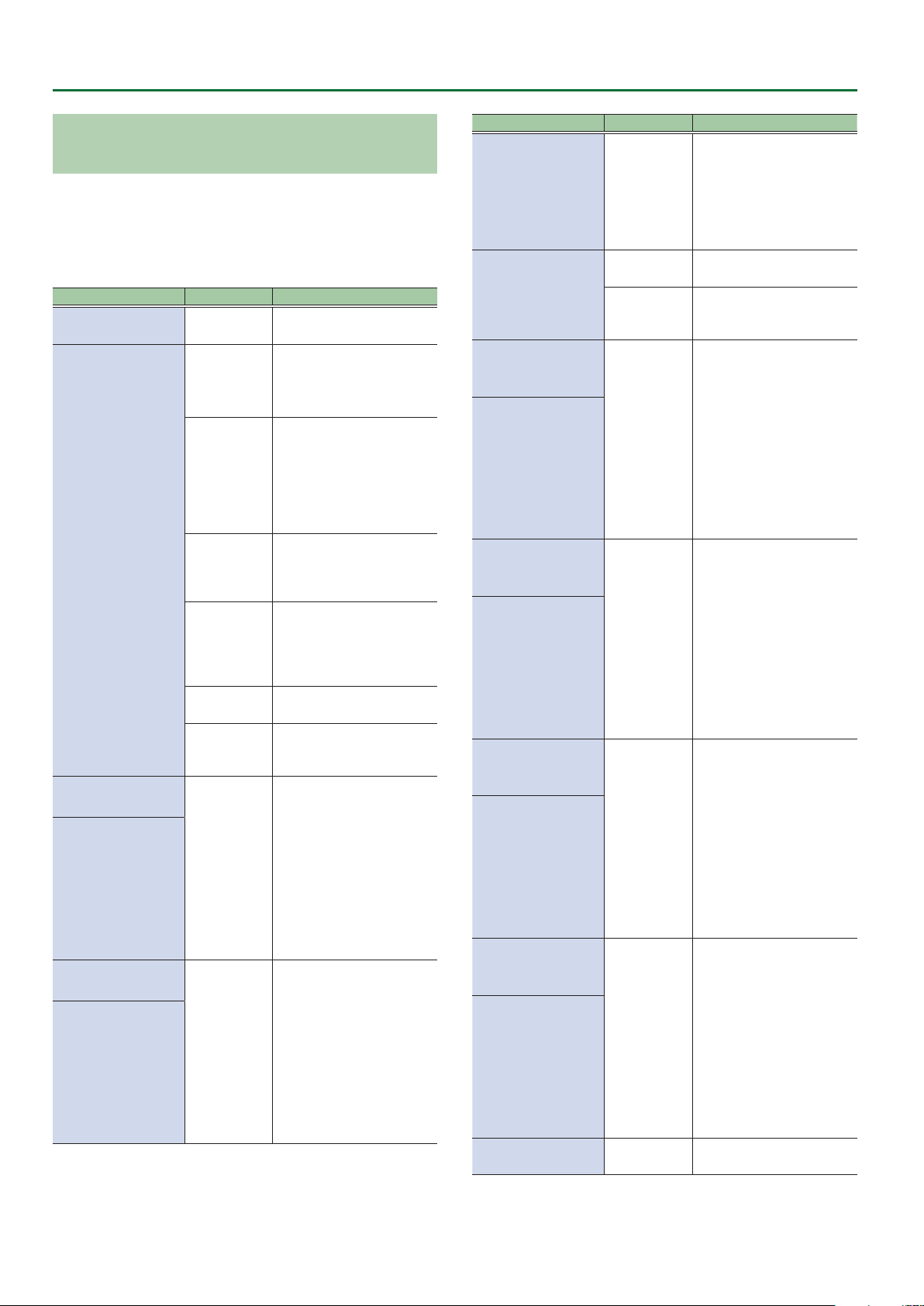
GR-300, ANALOG GR, POLY FX
INST
GK IN
Divided Pickup
Normal Pickup
GR-300
ANALOG GR
POLY FX
INST LEVEL
NOR MIX LEVEL
E.GUITAR, ACOUSTIC, AC BASS, E.BASS
INST
E.GUITAR
GK IN
Divided Pickup
Normal Pickup
ACOUSTIC
AC BASS
BASS
NOR MIX LEVEL
AMP
Modeling
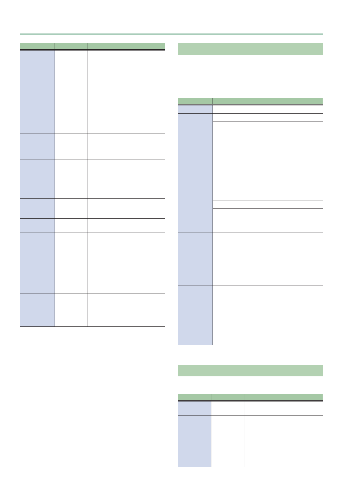
VIO GUITAR
GK IN
Divided Pickup
Normal Pickup
INST
GUITAR HARMO FILTER
INST LEVEL
INST LEVEL
NOR MIX LEVEL
23
Page 24
INST Parameters > INST TYPE
Parameters Common to Each INST TYPE (ALT TUNE)
Without changing the tuning of the guitar (bass) on which the
divided pickup is installed, you can instantly switch to a variety of
other tunings.
By using the ALT TUNE function for each INST, you can simultaneously
play a 6-string guitar and a 12-string guitar, create harmonies by
yourself, or play rich unison sounds.
Parameter Value Explanation
ON/OFF OFF, ON
OPEN D, OPEN
E, OPEN G,
OPEN A
*1
DROP D–
DROP A
*1
TUNING TYPE
PITCH 6–PITCH 1
*1 *3
PITCH LowB,
PITCH 4th,
PITCH 3rd,
PITCH 2nd,
PITCH 1st,
PITCH HiC
*2 *3
FINE 6–FINE 1
*1 *3
FINE LowB,
FINE 4th,
FINE 3rd,
FINE 2nd,
FINE 1st,
FINE HiC
*2 *3
D-MODAL
*1
NASHVL
*1
-12–+12 STEP
USER
-24–+24
-50–+50
Switches the alternate
tuning function on/o.
Tuning that produces a
major chord when you play
the open strings.
DROP-D is a tuning in
which only the 6th string
is dropped to D. The other
tunings are the variations
that are transposed
downward parallel to Drop
D.
Tuning that drops the 6th,
2nd, and 1st string by a
whole step to create an
ethnic feel.
Tuning that raises the 6th,
5th, 4th, and 3rd strings by
one octave; like a 12-string
guitar’s secondary strings by
themselves.
Raises/lowers the tuning of
all strings in semitone steps.
User tuning in which each
string can be specied
individually.
Species the amount of
pitch shift in semitones for
each string.
Finely adjusts the pitch of
each string. -50 is half a
semitone down; +50 is half
a semitone up.
Parameter Value Explanation
Turn this on if you want the
sound of a 12-string guitar.
12STR SW
*4
12STR TYPE
*4
12STR PITCH
6–12STR PITCH 1
*1 *4 *5
12PITCH LowB,
12PITCH 4th,
12PITCH 3rd,
12PITCH 2nd,
12PITCH 1st,
12PITCH HiC
*2 *4 *5
12STR LEVEL
6–12STR LEVEL 1
*1 *4 *5
12LEVEL LowB
12LEVEL 4th
12LEVEL 3rd
12LEVEL 2nd
12LEVEL 1st
12LEVEL HiC
*2 *4 *5
12STR FINE 6–12STR
FINE 1
*1 *4 *5
12FINE LowB,
12FINE 4th,
12FINE 3rd,
12FINE 2nd,
12FINE 1st,
12FINE HiC
*2 *4 *5
12STR DELAY
6–12STR DELAY 1
*1 *4 *5
12DELAY LowB,
12DELAY 4th,
12DELAY 3rd,
12DELAY 2nd,
12DELAY 1st,
12DELAY HiC
*2 *4 *5
STR BEND SW OFF, ON
OFF, ON
NORMAL
USER
-24–+24
0–100
-50–+50
0ms–100ms
This changes the sound of
a regular six-string guitar
to that of a twelve-string
guitar featuring secondary
strings.
The conventional tuning of
a 12-string guitar.
A user tuning that species
the pitch of each secondary
string.
This sets the amount of
pitch shift for secondary
strings, in semitone steps.
Species the volume of the
secondary strings.
Finely adjusts the pitch of
the secondary strings.
-50 is half a semitone down;
+50 is half a semitone up.
Adjusts the time the sound
of each secondary string
is delayed relative to the
respective main string.
Turns the String Bend
function on/o.
24
Page 25
INST Parameters > DYNAMIC SYNTH Parameters
Parameter Value Explanation
Setting this to 0 makes
for no shift in pitch by
bend, and setting it to 100
produces shifting according
BEND CONTROL 0–100
BEND DEPTH6–BEND
DEPTH1
*1
BEND DEPTH LowB,
BEND DEPTH 4th,
BEND DEPTH 3rd,
BEND DEPTH 2nd,
BEND DEPTH 1st,
BEND DEPTH HiC
*2
*1 Valid in the GUITAR MODE.
*2 Valid in the BASS MODE.
*3 Valid when the TUNING TYPE is set to USER.
*4 Valid when the INST TYPE is set to E.GUITAR, E.BASS, ACOUSTIC,
or AC BASS.
*5 Valid when the 12STR TYPE is set to USER.
-24–+24
to the settings for BEND
DEPTH6–BEND DEPTH1
(LowB–HiC). Normally, this
pitch bend is set to 0, and
the setting 0–100 assigned
with Control Assign is used.
This sets the amount of
pitch shift in each string
when the BEND CONTROL is
set to 100.
The amount of pitch shift
from the current pitch is set
in semitone increments.
DYNAMIC SYNTH Parameters
OSC
In the OSC section you specify the waveform that is the basis of the
synthesizer sound.
Parameter Value Explanation
Selects the waveform that is the basis of the sound.
SIN Sine wave
SAW Sawtooth wave
TRI Triangle wave
SQR Square wave
PWM
DETUNE SAW
NOISE Noise
FEEDBACK
OSC
WAVEFORM
PITCH -24–+24 Adjusts the pitch.
FINE -50–+50
PULSE WIDTH
*3
PWM ENV
ATTACK
*3
PITCH ENV
DEPTH
*3
*1
SUPER SAW
*1
INPUT
*2
0–100
-50–+50
-50–+50
Pulse wave (asymmetrical
rectangular wave)
Two sawtooth waves of slightly
dierent pitch
A sound containing high overtones
similar to guitar feedback playing.
Suitable for creating crisply
aggressive tones that stand out.
The sound of seven sawtooth
waves playing simultaneously.
Pitch-shifted sounds are added
to the center sound. This is
appropriate when creating rich
sounds such as strings.
The input signal is used without
modication.
When using a GK PATCH
The signal of the divided pickup is
used.
When using a NORMAL PATCH
The signal of the normal pickup is
used.
Species a ner adjustment than
PITCH.
Species the pulse width. This
species the width of the upper
portion of the rectangular wave as
a percentage of the overall cycle.
Smaller values produce a narrower
pulse, approaching a square wave
(pulse width = 50%).
Larger values widen the pulse,
producing a more distinctive
sound.
Uses the dynamics of the input
signal to control the pulse width
of PWM.
Values in the positive direction
speed up the release of the pulse
width, and values in the negative
direction slow down the attack of
the pulse width.
Species the depth to which PWM
is modulated by the dynamics of
the input signal.
25
Page 26
INST Parameters > DYNAMIC SYNTH Parameters
Parameter Value Explanation
DETUNE
*4
SHARPNESS
*5
FEEDBACK
*6
HARMONICS
*6
S-SAW
DETUNE
*7
P. ENV ATTACK -50–+50
P. ENV DEPTH -50–+50
P. BEND
DEPTH
P. BEND CTL 0–100
SYNC SW
*8 *9
RING SW
*8
*1 Valid for the GK PATCH.
*2 If INPUT is selected as WAVEFORM, there are no editable
parameters in the OSC block.
*3 Valid when the WAVEFORM is set to PWM.
*4 Valid when the WAVEFORM is set to DETUNE SAW.
*5 Valid when the WAVEFORM is set to NOISE.
*6 Valid when the WAVEFORM is set to FEEDBACK OSC.
*7 Valid when the WAVEFORM is set to SUPER SAW.
*8 Valid only when the INST1 TYPE (p. 23) is set to DYNAMIC
SYNTH.
*9 Valid when the WAVEFORM is set to other than NOISE or INPUT.
-50–+50 Species the amount of detuning.
Species the frequency range
0–100
0–100
0–100
0–100
-24–+24 Species the depth of bend.
OFF, ON
OFF, ON
of the noise that is heard. Larger
values strengthen the sense of
pitch.
Adjusts the amount of feedback.
Larger values increase the amount
of feedback, changing the volume
of the harmonics.
Species the tonal character of the
harmonics.
Species the amount of pitch
spread between the seven
sawtooth waves that are layered
within one oscillator.
Uses the dynamics of the input
signal to control the pitch.
Values in the positive direction
speed up the pitch release, and
values in the negative direction
slow down the pitch attack.
Species the depth to which pitch
is modulated by the dynamics of
the input signal.
This parameter controls the bend.
Assign this when using a CTL pedal
or EXP pedal to control bend.
Switches oscillator sync on/o.
If this is ON, it generates a complex
waveform by forcibly resetting
INST2 and INST3 to the beginning
of their cycle in synchronization
with the INST1 frequency.
Switches the ring modulator on/o.
If this is on, the signals of INST1
and INST2 (or INST1 and INST3)
are multiplied with each other to
produce a complex waveform.
FILTER
Sound consists of numerous overtones at various frequencies. By
using a lter to pass or cut the overtones of specic frequency
regions, you can modify the brightness of the sound.
In the FILTER section you can modify the brightness of the sound
by changing the type of lter and applying various changes to the
output waveform.
Parameter Value Explanation
ON/OFF OFF, ON Switches lter on/o.
Type of lter
The region above the cuto
LPF
HPF
TYPE
BPF
PKG
LADDER LPF A ladder-type low-pass lter.
LADDER HPF A ladder-type high-pass lter.
SLOPE
*1
CUTOFF 0–100 Adjusts the cuto frequency.
RESONANCE 0–100
F. ENV ATTACK -50–+50
F. ENV DEPTH -50–+50
*1 Valid when the TYPE is set to LPF, HPF, BPF, PKG.
-12 dB, -24 dB
frequency will be cut, making the
sound more mellow.
The region below the cuto
frequency will be cut, emphasizing
the high-frequency range.
It passes only the range of
frequencies in the region of the
cuto frequency, cutting the other
frequencies.
Boosts the range of frequencies in
the region of the cuto frequency.
Selects the slope (steepness) of the
low-pass lter.
Resonance emphasizes the sound
in the region of the lter cuto
frequency.
Increasing the resonance setting
will increase this emphasis,
producing a distinctive sound that
is characteristic of synthesizers.
Species how the dynamics of the
input signal controls the lter.
Values in the positive direction
speed up the lter release. Values in
the negative direction slow down
the lter attack.
Species the depth to which the
lter is modulated by the dynamics
of the input signal.
AMP
In the AMP section you can modify the sound by changing its volume
and dynamics.
Parameter Value Explanation
A. ENV
ATTACK
LOW CUT
HIGH CUT
-50–+50
FLAT, 20.0
Hz–16.0 kHz
20.0 Hz–16.0
kHz, FLAT
Species how the dynamics of the
input signal controls the amp.
Cuts the frequency region below the
specied frequency. When FLAT is
selected, the low cut lter will have
no eect.
Cuts the frequency region above the
specied frequency. When FLAT is
selected, the high cut lter will have
no eect.
26
Page 27
INST Parameters > DYNAMIC SYNTH Parameters
LFO1, LFO2
Here you can cyclically modulate the sound by applying vibrato to
modulate the pitch or applying tremolo to modulate the volume.
Parameter Value Explanation
ON/OFF OFF, ON Turns the LFO1/LFO2 on/o.
Selects the waveform of LFO1 and LFO2.
SIN Sine wave
SAW UP Sawtooth wave
SHAPE
RATE
*3
DYNAMIC DEPTH OFF, ON
PITCH DEPTH 0–100
FILTER DEPTH 0–100
AMP DEPTH 0–100
PWM DEPTH
*1
FADE TIME
*2
SYNC OFF, ON
BPM 40–250
VARIATION1&2 PATCH, 01–50
*1 Valid when the WAVEFORM (p. 25) in the OSC section is set to
PWM.
*2 Valid when the DYNAMIC DEPTH is ON.
*3 Refer to “About eects when a note value is selected as a setting”
(p. 66).
SAW DOWN
TRI Triangle wave
SQR Square wave
RANDOM Random wave
S&H Sample and Hold
0–100, BPM
Œ–`
0–100
0–100
Sawtooth wave (negative
polarity)
Determines the speed of the
LFO1/LFO2.
Species whether the dynamics
of the input signal controls the
depth at which LFO1 and LFO2
are applied.
Allows the LFO to modulate
the pitch, producing a vibrato
eect.
Allows the LFO to modulate
the FILTER CUTOFF (cuto
frequency),
Allows the LFO to modulate the
AMP LEVEL (volume), producing
a tremolo eect.
Adjusts the depth at which
PWM is modulated.
Species the time until the LFO
reaches its maximum amplitude.
If SYNC is ON, you can use the
CONTROL FUNCTION parameter
SYNC TRIG (p. 68) or the
ASSIGN SETTING parameter
SYNC RETRIGGER (p. 73) to
retrigger the start timing of the
LFO.
Adjusts the BPM value for each
patch.
LFO1 and LFO2 settings can be
saved/loaded as 50 dierent
variations.
A saved VARIATION can be
loaded into a dierent patch,
which is convenient when
you’re creating sounds.
SEQ
This is a step sequencer function with up to 16 steps. You can create
complex changes by combining steps with a dierent envelope at
each step.
COMMON
Parameter Value Explanation
SEQUENCER1, SEQUENCER2,
and TARGET settings can be
saved/loaded as 50 dierent
VARIATION1&2 PATCH, 01–50
SEQUENCER 1, SEQUENCER 2
Parameter Value Explanation
ON/OFF OFF, ON
SYNC OFF, ON
1SHOT OFF, ON
TURBO OFF, ON
RATE
*1
LOOP
LENGTH
0–100, BPM
Œ–`
1–16
TARGET
Parameter Value Explanation
PITCH
*2
CUTOFF
LEVEL
*1 Refer to “About eects when a note value is selected as a setting”
(p. 66).
*2 If the OSC section’s WAVEFORM (p. 25) is set to INPUT, the
PITCH does not change.
OFF, SEQ1,
SEQ2
OFF, SEQ1,
SEQ2
OFF, SEQ1,
SEQ2
variations.
A saved VARIATION can be
loaded into a dierent patch,
which is convenient when
you’re creating sounds.
Turns the SEQUENCER1/
SEQUENCER2 on/o.
Species whether the start timing
of the LFO for which SYNC is ON is
synchronized with the SEQUENCER.
The start timing is retriggered
using the CONTROL FUNCTION
parameter SYNC TRIG (p. 68) or
the ASSIGN SETTING parameter
SYNC RETRIGGER (p. 73).
If this is on, the steps specied by
the LOOP LENGTH of SEQUENCER1
and SEQUENCER2 will play only
once.
If this is ON, operation is twice as
fast as specied by RATE.
Species the rate at which the
sequence pattern of SEQUENCER1
or SEQUENCER2 repeats.
Species the length (number
of steps) of SEQUENCER1 or
SEQUENCER2 that is repeated.
Species the SEQUENCER that is
assigned to the OSC section’s PITCH
(p. 25).
Species the SEQUENCER that is
assigned to the FILTER section’s
CUTOFF (p. 26).
Species the SEQUENCER that is
assigned to the INST COMMON
section’s INST LEVEL (p. 23).
27
Page 28
INST Parameters > DYNAMIC SYNTH Parameters
SEQ1, SEQ2
Parameter Value Explanation
PITCH STEP1–
STEP 16 MAX
PITCH STEP1–
STEP16 MIN
CUTOFF STEP1–
STEP16 MAX
CUTOFF STEP1–
STEP16 MIN
LEVEL STEP1–
STEP16 MAX
LEVEL STEP1–
STEP16 MIN
STEP1–STEP16
CURVE
-24–+24
0–100
0–100
Specify the curve of change for each step of
SEQUENCER1 and SEQUENCER2.
Specify the width of pitch
change for each step.
Specify the width of cuto
change for each step.
Specify the width of inst level
change for each step.
About SEQUENCER
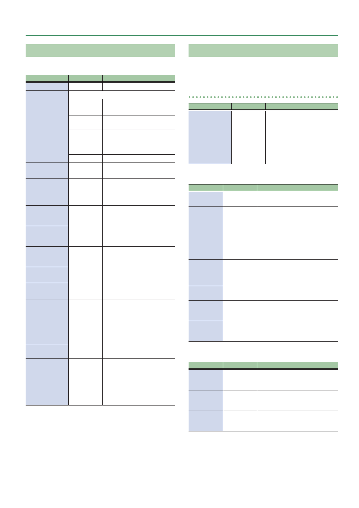
If you make eight steps of sequence settings with STEP CURVE, PITCH
MIN, and PITCH MAX set as shown in the table below, the output will
be as indicated by the graph.
Example of an eight-step sequence
STEP 1 2 3 4 5 6 7 8
STEP
CURVE
PITCH
MIN
PITCH
MAX
-12 -9 -6 -3 0 +3 +6 +9
-9 -6 -3 0 +3 +6 +9 +12
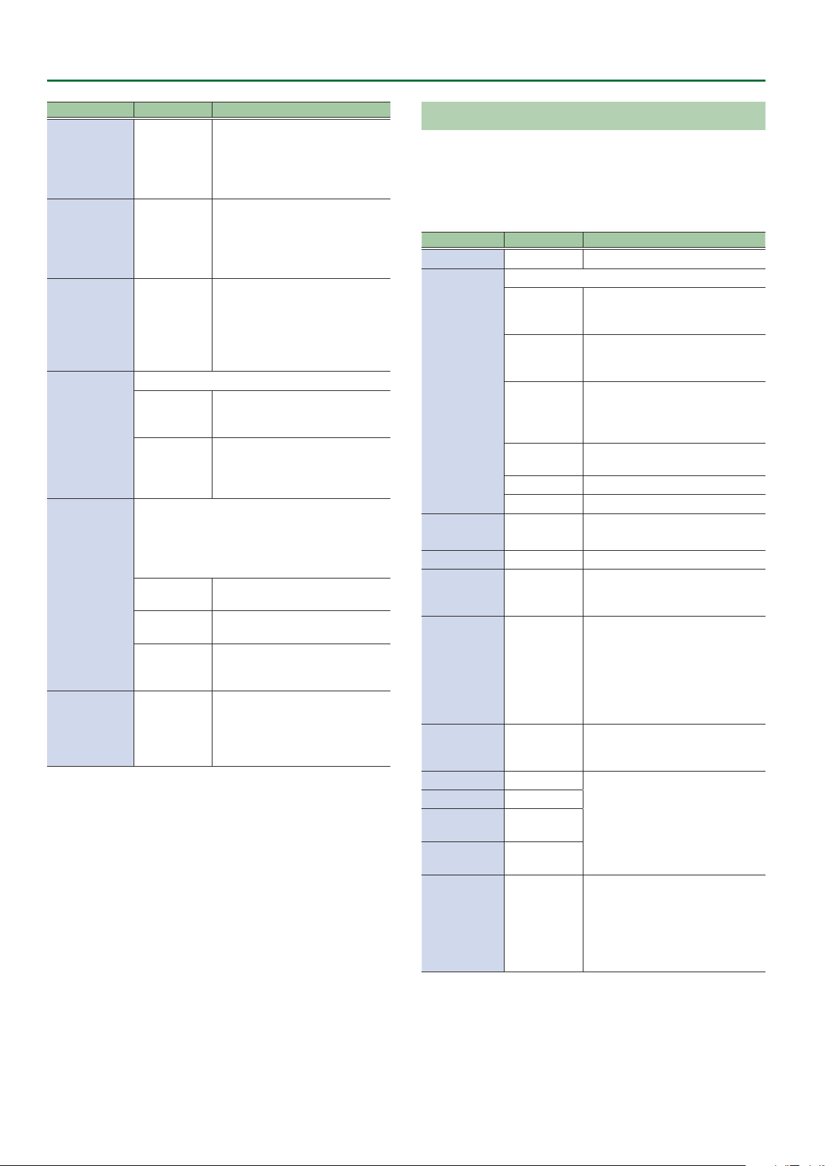
Editing the sequencer
1. Turn the [6] knob to select “SEQ.”
2. Press the [6] knob.
The SEQUENCE COMMON screen appears.
3. Specify how SEQUENCER1 and SEQUENCER2
operate.
Knob Explanation
[1] knob
[2] knob Set the parameters of SEQUENCER1.
[4] knob Set the parameters of SEQUENCER2.
[6] knob
4. Use the [K] [J] (PAGE) buttons to switch to the
SEQUENCER1 or SEQUENCER2 screens.
Accesses the SEQUENCER1 and
SEQUENCER2 VARIATION screen.
Specify which sequencer controls
PITCH, CUTOFF, and LEVEL.
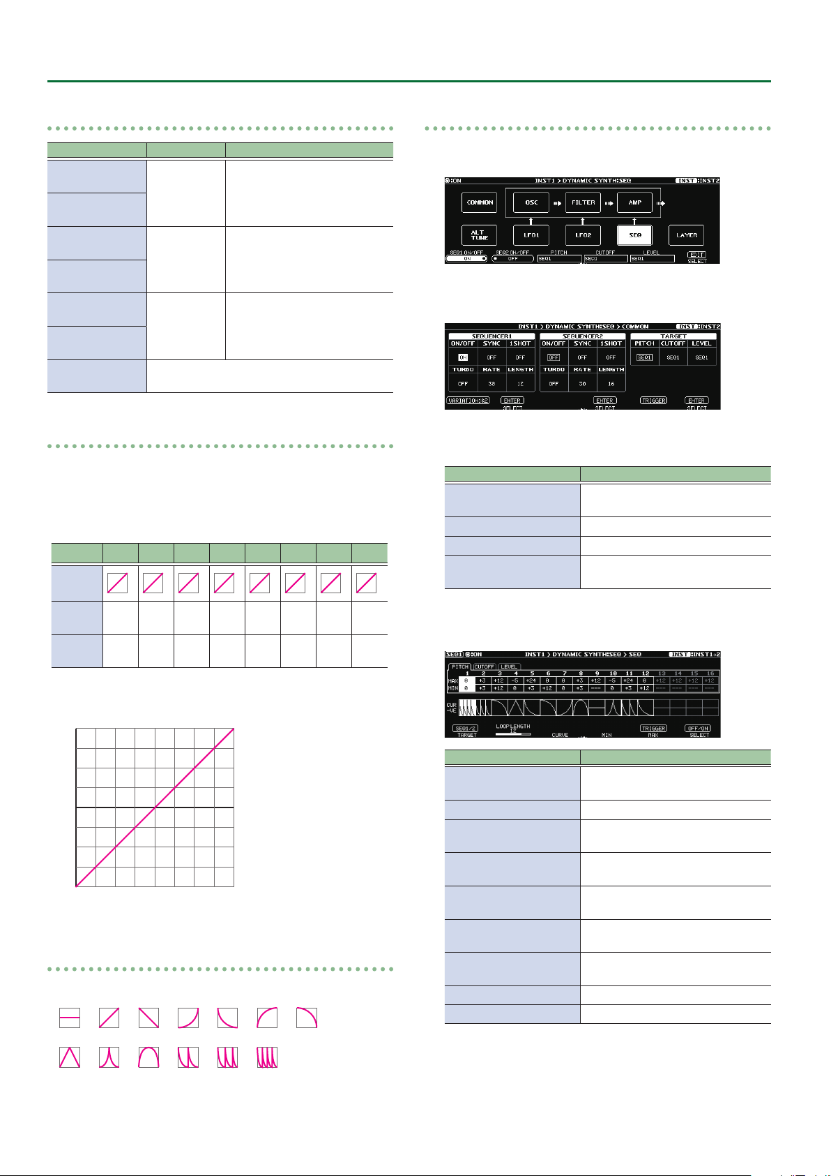
Output example
+12
+9
+6
+3
0
-3
-6
-9
-12
STEP 1
STEP 2
STEP 3
STEP 4
STEP 5
STEP 6
STEP 7
STEP 8
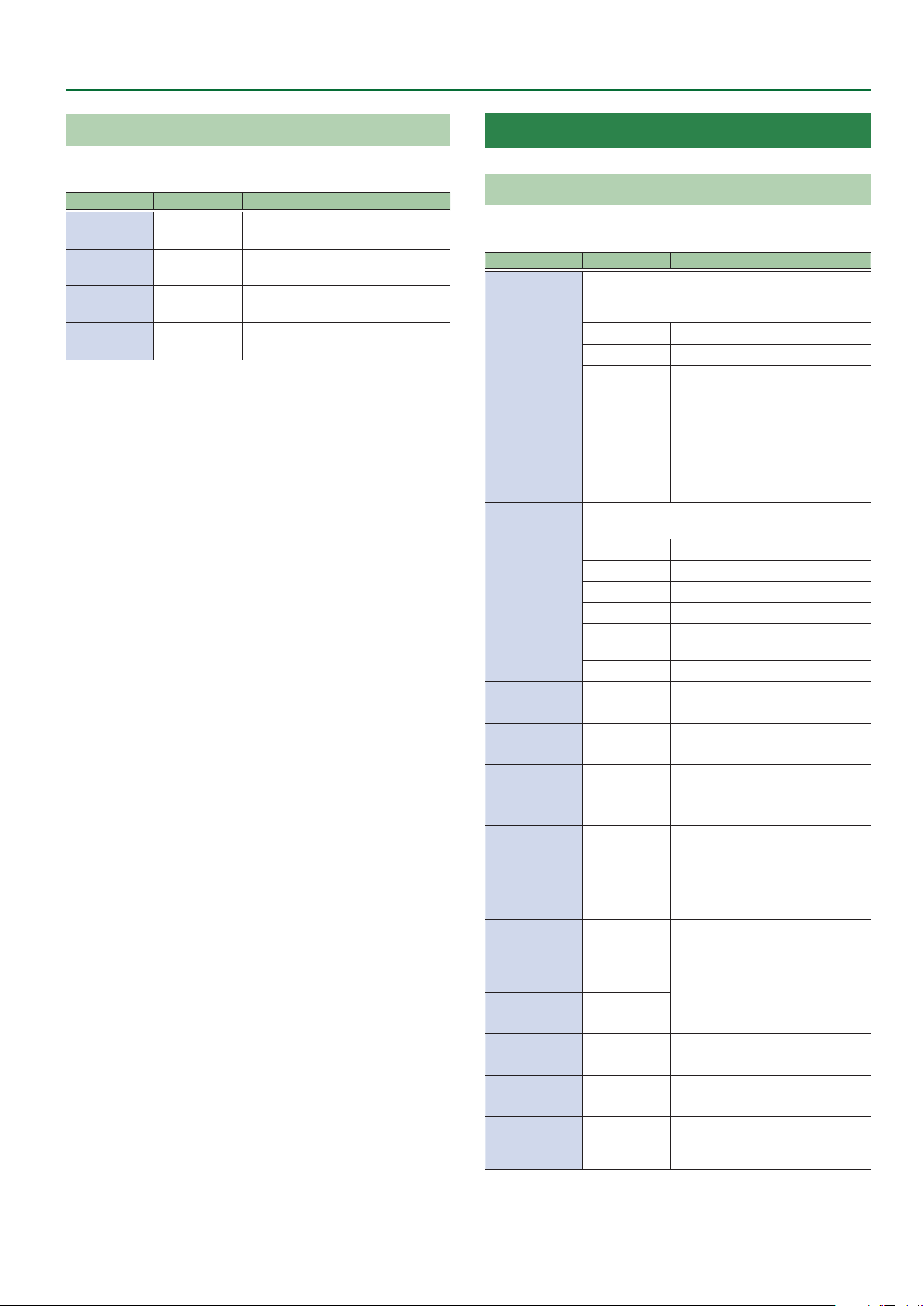
About STEP CURVE
STEP CURVE provides a choice of the following 13 types.
Operation Explanation
Turn the [1] knob
Press the [1] knob Switch the SEQ1 and SEQ2 screens.
Turn the [2] knob
Turn the [3] knob
Turn the [4] knob
Turn the [5] knob
Press the [5] knob
Turn the [6] knob Select the step to edit.
Press the [6] knob Switch the sequencer on/o.
* If a parameter to be controlled (PITCH, CUTOFF, LEVEL) is not
assigned to the sequencer, these settings have no eect (they are
shown in gray).
* Settings of steps that are beyond the value specied by LENGTH
have no eect (they are shown in gray).
Switch the TARGET editing screen
(PITCH, CUTOFF, LEVEL).
Specify the LOOP LENGTH (length of
the sequencer loop).
Specify the CURVE of the selected
step.
Adjust the MIN value of the
parameter selected by the cursor.
Adjust the MAX value of the
parameter selected by the cursor.
Retrigger the LFO or SEQUENCER for
which SYNC (p. 27) is ON.
28
Page 29
INST Parameters > OSC SYNTH Parameters
LAYER
Here you can specify the range of notes that are sounded. This is
useful when layering multiple sounds together.
Parameter Value Explanation
L. FADE 1–60
LOWER A0–E6
UPPER A0–E6
U. FADE 1–60
* Valid when the WAVEFORM (p. 25) in the OSC section is set to
other than INPUT.
Species the area over which the
low range will fade out.
Species the lowest note of the
range that will sound.
Species the highest note of the
range that will sound.
Species the area over which the
high range will fade out.
OSC SYNTH Parameters
OSC
In the OSC section you specify the waveform that is the basis of the
synthesizer sound.
Parameter Value Explanation
This creates the waveform that determines the
character of the sound, and also species the pitch.
There are two oscillators (OSC1 and OSC2).
SINGLE Only OSC1 is used.
DUAL OSC1 and OSC2 are used.
MODE
SYNC
RING
Selects the waveform that is the basis of the
sound.
SIN Sine wave
WAVEFORM1
WAVEFORM2
PITCH1
PITCH2
FINE1
FINE2
PULSE WIDTH1
PULSE WIDTH2*10–100 Species the pulse width.
SAW Sawtooth wave
TRI Triangle wave
SQR Square wave
PWM
NOISE Noise
-24–+24 Adjusts the pitch.
-50–+50
This is oscillator sync. It generates
a complex waveform by forcibly
resetting OSC2 to the beginning
of its cycle in synchronization with
the OSC1 frequency.
This is a ring modulator. It
generates a complex waveform by
multiplying OSC1 and OSC2.
Pulse wave (asymmetrical
rectangular wave)
Species a ner adjustment than
PITCH.
PW MOD
RATE1
PW MOD
RATE2
*1
P. ENV
ATTACK1
P. ENV
ATTACK2
P. ENV DECAY1
P. ENV DECAY2
P. ENV DEPTH1
P. ENV DEPTH2
LEVEL1
LEVEL2
MONO/POLY
SW
0–100
0–100
0–100
0–100
0–100
MONO, POLY
Species the depth to which the
LFO will modulate pulse width.
Species the attack/decay time of
the pitch envelope.
Species the depth to which the
envelope will modulate the pitch.
Species the volume of the
oscillator.
If this is set to MONO, only a single
note will sound even if you play a
chord.
29
Page 30
INST Parameters > OSC SYNTH Parameters
Parameter Value Explanation
Turn this “ON” if you want to play
tones in semitone increments.
CHROMATIC OFF, ON
PORTA SW OFF, ON
PORTA TIME 0–100
Selects how portamento is applied.
PORTA MODE
*2
HOLD MODE
LOW VELO CUT OFF, 1–10
*1 Valid when the WAVEFORM1 or WAVEFORM2 is set to PMW.
*2 Valid when the MONO/POLY SW is set to POLY.
MODE1
MODE2
Species the operation of the Hold function using
CONTROL FUNCTION and ASSIGN FUNCTION.
* In order to use the Hold function, make settings
for “CONTROL FUNCTION” (p. 67) and “ASSIGN
SETTING” (p. 70).
MODE1
MODE2
MODE3
If this is “ON,” the pitch will change
in semitone steps even when you
bend notes.
Species whether portamento is
applied.
When this is set to ON, you can
create a smooth change in pitch
from one note to the next.
Species the time required for
the pitch change when using
portamento.
Larger values lengthen the time
during which the pitch of the next
note is reached.
The portamento eect is applied
starting at the nal pitch sounded
by each string.
The portamento eect is applied
starting at the nal pitch sounded,
regardless of the string that was
played.
Notes that are newly played while
Hold is on will also be held.
Newly played notes are not
accepted while Hold is on.
While Hold is on, notes newly
played on a string that’s being
held are accepted.
Adjust this if simply touching
a string causes a note to be
unintentionally triggered. Raising
this value will make it more
dicult to trigger notes.
FILTER
Sound consists of numerous overtones at various frequencies. By
using a lter to pass or cut the overtones of specic frequency
regions, you can modify the brightness of the sound.
In the FILTER section you can modify the brightness of the sound
by changing the type of lter and applying various changes to the
output waveform.
Parameter Value Explanation
ON/OFF OFF, ON Switches lter on/o.
Type of lter
The region above the cuto
LPF
HPF
TYPE
BPF
PKG
LADDER LPF A ladder-type low-pass lter.
LADDER HPF A ladder-type high-pass lter.
SLOPE
*1
CUTOFF 0–100 Adjusts the cuto frequency.
CUTOFF
FOLLOW
RESONANCE 0–100
VELOCITY
SENS
F. ENV ATTACK 0–100
F. ENV DECAY 0–100
F. ENV
SUSTAIN
F. ENV
RELEASE
F. ENV DEPTH -50–+50
-12 dB, -24 dB
0–100
-50–+50
0–100
0–100
frequency will be cut, making the
sound more mellow.
The region below the cuto
frequency will be cut, emphasizing
the high-frequency range.
It passes only the range of
frequencies in the region of the
cuto frequency, cutting the other
frequencies.
Boosts the range of frequencies in
the region of the cuto frequency.
Selects the slope (steepness) of the
low-pass lter.
Species how the cuto frequency
will be aected by the note
position.
Resonance emphasizes the sound
in the region of the lter cuto
frequency.
Increasing the resonance setting
will increase this emphasis,
producing a distinctive sound that
is characteristic of synthesizers.
Species how the lter envelope
depth is aected by your picking
dynamics.
Species the attack/decay/sustain
level/ release time of the lter
envelope.
Species the depth and direction of
the cuto frequency change.
Higher values make the cuto
frequency move upward.
Lower values make the cuto
frequency move downward.
30
*1 Valid when the TYPE is set to LPF, HPF, BPF, or PKG.
Page 31

INST Parameters > OSC SYNTH Parameters
AMP
In the AMP section you can modify the sound by changing its volume
and dynamics.
Parameter Value Explanation
Species the sensitivity to the
VELOCITY SENS 0–100
A. ENV ATTACK 0–100
A. ENV DECAY 0–100
A. ENV SUSTAIN 0–100
A. ENV RELEASE 0–100
LOW CUT
HIGH CUT
FLAT, 20.0
Hz–16.0 kHz
20.0 Hz–16.0
kHz, FLAT
strength at which you pick the
string.
Species the attack/decay/
sustain level, and release time of
the AMP.
Cuts the frequency region
below the specied frequency.
When FLAT is selected, the low
cut lter will have no eect.
Cuts the frequency region
above the specied frequency.
When FLAT is selected, the high
cut lter will have no eect.
LFO1, LFO2
Parameter Value Explanation
Species whether the start
timing of the LFO for which
SYNC is ON is synchronized with
the SEQUENCER.
SYNC OFF, ON
BPM 40–250
VARIATION1&2 PATCH, 01–50
*1 Refer to “About eects when a note value is selected as a setting”
(p. 66).
The start timing is retriggered
using the CONTROL FUNCTION
parameter SYNC TRIG (p.
68) or the ASSIGN SETTING
parameter SYNC RETRIGGER (p.
73).
Adjusts the BPM value for each
patch.
LFO1 and LFO2 settings can be
saved/loaded as 50 dierent
variations.
A saved VARIATION can be
loaded into a dierent patch,
which is convenient when
you’re creating sounds.
Here you can cyclically modulate the sound by applying vibrato to
modulate the pitch or applying tremolo to modulate the volume.
Parameter Value Explanation
ON/OFF OFF, ON Turns the LFO1/LFO2 on/o.
Selects the waveform of LFO1 and LFO2.
SIN Sine wave
SAW UP Sawtooth wave
SHAPE
RATE
*1
PITCH1 DEPTH
PITCH2 DEPTH
FILTER DEPTH 0–100
AMP DEPTH 0–100
DELAY TIME 0–100
FADE TIME 0–100
SAW DOWN
TRI Triangle wave
SQR Square wave
RANDOM Random wave
S&H Sample and Hold
0–100, BPM
Œ–`
0–100
Sawtooth wave (negative
polarity)
Determines the speed of the
LFO1/LFO2.
Allows the LFO to modulate
the pitch, producing a vibrato
eect.
Allows the LFO to modulate
the FILTER CUTOFF (cuto
frequency),
Allows the LFO to modulate the
AMP LEVEL (volume), producing
a tremolo eect.
Species the time from when
a note is played until the LFO
begins to apply.
Species the time until the LFO
reaches its maximum amplitude.
31
Page 32

INST Parameters > GR-300 (In GUITAR MODE) / ANALOG GR (In BASS MODE) Parameters
GR-300 (In GUITAR MODE) / ANALOG GR (In BASS MODE) Parameters
GR-300/ANALOG GR
Parameter Value Explanation
Species whether to sound the hexa-VCO
(sawtooth wave), the hexa-distortion (square wave),
or both.
MODE
COMP SW
*1
CUTOFF 0–100
RESONANCE 0–100
ENV MOD SW
ENV MOD
SENS
ENV MOD
ATTACK
PITCH SW
*1
PITCH A
PITCH B
*1
VCO Only the hexa-VCO will sound.
V+D
DIST Only the hexa-distortion will sound.
OFF, ON
This automatically changes the VCF cuto
frequency according to the amplitude of the string
vibration. This allows you to change the tone with a
wah-like eect each time you pick a string.
OFF Turns envelope modulation o.
ON
INV
0–100
0–100
OFF, A, B
-12–+12
The hexa-VCO and hexa-distortion
will sound together.
If this is “ON,” the decay time of the
hexa-VCO will be extended.
Adjusts the cuto frequency at
which the lter cuts o the sound’s
harmonic components.
Adjusts the amount of lter
resonance (distinctiveness of the
sound) used.
This causes the VCF cuto
frequency to change from a high to
low frequency each time the string
is picked.
This produces a wah-like eect,
with the sound going from high
frequencies to low.
As opposed to the ON setting, this
allows you to have the VCF cuto
frequency change from a low to
high frequency each time the string
is picked.
This produces a reverse wah-like
eect, with the sound going from
high frequencies to low.
Adjusts the input sensitivity of
the envelope modulation. As the
value is raised, the change from
the envelope modulation broadens
with even weaker picking.
Adjusts the attack time for the
change in the envelope modulation
produced by picking.
Raising the value slows the attack
for this change.
This setting allows you to switch
A, B and OFF the pitch shift, which
enables the pitch of the HEXA-VCO
sound to shift in response.
* Pitch shift applies only to the
hexa-VCO; it does not apply to
hexa-distortion.
This sets the amount of shift in
pitch from the original sound in
semitone increments.
Parameter Value Explanation
FINE A
FINE B
*1
DUET SW
*1
SWEEP SW
*1
SWEEP RISE
*1
SWEEP FALL
*1
VIBRATO SW
*1
VIBRATO RATE
*1
VIBRATO
DEPTH
*1
LOW CUT
HIGH CUT
*1 Valid when the MODE is set to VCO or V+D.
-50–+50
OFF, ON
OFF, ON
0–100
0–100
OFF, ON
0–100 Adjusts the rate of the vibrato.
0–100 Adjusts the depth of the vibrato.
FLAT, 20.0
Hz–16.0 kHz
20.0 Hz–16.0
kHz, FLAT
This nely adjusts the pitch. -50 is
half a semitone down; +50 is half a
semitone up.
If this is “ON,” a sawtooth wave
at the same pitch as the original
sound will be added to the hexaVCO, making the sound richer.
MEMO
By setting the hexa-VCO’s pitch
shift to a PITCH setting such as
+/-12 (an octave up/down), +/- 7
(a perfect fth), or +/-5 (a perfect
fourth), you can create thick,
synthesizer-like sounds.
By setting PITCH FINE to about “+/5” to slightly skew the pitch shift
of the hexa-VCO, you can give the
sound greater depth.
This is a Sweep function that
smoothly changes the amount of
shift when you use PITCH SW to
vary the amount of pitch shift.
Adjusts the amount of time for
the pitch to shift when the PITCH
SW parameter is switched and the
sound changes to a higher pitch.
If this is “0,” the change will occur
instantly; higher values produce
slower change.
Adjusts the amount of time for
the pitch to shift when the PITCH
SW parameter is switched and the
sound changes to a lower pitch.
If this is “0,” the change will occur
instantly; higher values produce
slower change.
Allows you to apply electronic
vibrato to the hexa-VCO.
Cuts the frequency region below
the specied frequency. When FLAT
is selected, the low cut lter will
have no eect.
Cuts the frequency region above
the specied frequency. When FLAT
is selected, the high cut lter will
have no eect.
32
Page 33

INST Parameters > E.GUITAR Parameters
E.GUITAR Parameters
GUITAR (In GUITAR MODE)
Parameter Value Explanation
TYPE Select the electric guitar type “TYPE” (p. 33).
Selects the pickup position.
REAR Rear pickup
R+C
*1
CENTER
*1
PU SELECT
TONE TYPE
*4
SENS
*4
DEPTH
*4
ATTACK
*4
RESONANCE
*4
DIRECT LEVEL
*4
VOLUME 0–100
TONE 0–100
*1 Valid when the TYPE is set to CLA-ST, MOD-ST, or LIPS.
*2 Valid when the TYPE is set to TE, LP, P-90, 335, L4, RICK, WIDE
RANGE, or BRIGHT HUM.
*3 Valid when the TYPE is set to LIPS.
*4 Valid when the TYPE is set to FRETLESS.
C+F
*1
FRONT Front pickup
R+F
*2
ALL
*3
MILD,
STANDARD,
BRIGHT1,
BRIGHT2
0–100 This controls the input sensitivity.
0–100
0–100
0–100
0–100
TYPE
Value Explanation
The sound of a Fender Stratocaster. Simulates the
CLA-ST
MOD-ST
TE
installation of three single-coil pickups (passive
type).
This models a guitar with three EMG active singlecoil pickups.
The sound of a Fender Telecaster. This models a
guitar with two single-coil pickups.
Rear and center pickups
Center pickup
Center and front pickups
Rear and front pickups
All pickups
Selects the fretless tone type.
This controls the volume of the
harmonics.
Adjusts the attack of the picking
sound.
Adds a characteristically resonant
quality to the sound.
Adjusts the volume of the direct
sound.
Adjusts the volume. With a setting
of 0, there will be no sound.
Adjusts the tone of the body. The
standard value is 100; lowering the
value creates a softer tone.
Value Explanation
The sound of a Gibson Les Paul Standard. Simulates
LP
P-90
335
L4
RICK
LIPS
WIDE RANGE
BRIGHT HUM
FRETLESS This models a fretless guitar.
the installation of two humbucking pickups (passive
type).
The sound of a Gibson Les Paul Junior. This provides
two single-coil pickups of the type used on xedneck guitars and aectionately known as soap-bar
or dog-ear pickups.
The sound of a Gibson ES-335 Dot. Typical semiacoustic guitar with two humbucking pickups.
The sound of a Gibson L-4 CES. Acoustic body guitar
suited for jazz.
Equipped with two humbucking pickups and strung
with at wound strings.
This models a Rickenbacker 360. Semi-hollow body
guitar with two unique single-coil pickups.
The sound of a Danelectro 56-U3. This models a
guitar equipped with three pickups noted for their
visual resemblance to lipstick tubes.
This produces the fat sound typical of a larger
number of coil windings than on a conventional
single-coil pickup.
A conventional humbucking pickup places two coils
side by side, causing the high frequencies to be
canceled; however, this model produces a tone that
preserves these high frequencies while retaining the
characteristics of a humbucking pickup.
GUITAR (In BASS MODE)
Parameter Value Explanation
Select the electric guitar type.
The sound of a Fender Stratocaster.
TYPE
PU SELECT
TONE TYPE
*3
SENS
*3
DEPTH
*3
ST
LP
FRETLESS This models a fretless guitar.
Selects the pickup position.
REAR Rear pickup
R+C
*1
CENTER
*1
C+F
*1
FRONT Front pickup
R+F
*2
MILD,
STANDARD,
BRIGHT1,
BRIGHT2
0–100 This controls the input sensitivity.
0–100
Simulates the installation of three
single-coil pickups (passive type).
The sound of a Gibson Les Paul
Standard. Simulates the installation
of two humbucking pickups
(passive type).
Rear and center pickups
Center pickup
Center and front pickups
Rear and front pickups
Selects the fretless tone type.
This controls the volume of the
harmonics.
33
Page 34

INST Parameters > E.GUITAR Parameters
Parameter Value Explanation
ATTACK
*3
RESONANCE
*3
DIRECT LEVEL
*3
VOLUME 0–100
TONE 0–100
*1 Valid when the TYPE is set to ST.
*2 Valid when the TYPE is set to LP.
*3 Valid when the TYPE is set to FRETLESS.
0–100
0–100
0–100
Adjusts the attack of the picking
sound.
Adds a characteristically resonant
quality to the sound.
Adjusts the volume of the direct
sound.
Adjusts the volume. With a setting
of 0, there will be no sound.
Adjusts the tone of the body. The
standard value is 100; lowering the
value creates a softer tone.
AMP (AMP Modeling)
(When E.GUITAR, ACOUSTIC, AC BASS, or E.BASS is selected)
Parameter Value Explanation
ON/OFF OFF, ON Turns the AMP on/o.
TYPE Select the amp type “TYPE” (p. 34).
GAIN 0–120
SAG -10–+10
RESONANCE -10–+10
LEVEL 0–100
BASS 0–100
MIDDLE 0–100
TREBLE 0–100
PRESENCE 0–100
BRIGHT OFF, ON
GAIN SW
SOLO SW OFF, ON
LOW, MIDDLE,
HIGH
Adjusts the distortion of the
amp.
Adjusts the amount by which
compression changes in
response to the power amp.
Adjusts the amount by which
dynamics is aected by the
interaction between the
power amp and the speaker
transformer.
Adjusts the volume of the
entire preamp.
* Be careful not to raise the
Level setting too high.
Adjusts the tone for the low
frequency range.
Adjusts the tone for the
middle frequency range.
Adjusts the tone for the high
frequency range.
Adjusts the tone for the ultra
high frequency range.
Turns the bright setting on/
o.
* BRIGHT is valid for some of
the amps in TYPE.
Provides for selection from
three levels of distortion:
LOW, MIDDLE, and HIGH.
Distortion will successively
increase for settings of LOW,
MIDDLE and HIGH.
* The sound of each Type is
created on the basis of the
level of MIDDLE.
The tone to one suitable for
solos.
Parameter Value Explanation
SOLO LEVEL 0–100
SP TYPE Select the speaker type “SP TYPE” (p. 35).
MIC TYPE
MIC DISTANCE
MIC POSITION
MIC LEVEL 0–100
DIRECT LEVEL 0–100
VARIATION PATCH, 01–10
This setting selects the simulated mic type “MIC
TYPE” (p. 35).
SHORT, MEDIUM,
LONG
This simulates the mic position.
CENTER
1 cm–10 cm
Adjusts the volume level
when the SOLO SW is ON.
Simulates the distance
between the mic and
speaker.
The distance from
the speakers is
farther in the order of
SHORT<MEDIUM<LONG.
Simulates the condition that
the mic is set in the middle
of the speaker cone.
Simulates the condition that
the mic is moved away from
the center of the speaker
cone.
Adjusts the volume of the
mic.
Adjusts the volume of the
direct sound.
AMP settings can be saved/
loaded as ten dierent
variations.
A saved VARIATION can be
loaded into a dierent patch,
which is convenient when
you’re creating sounds.
These variations are shared
with the AMP setting in
EFFECT.
TYPE
Value Explanation
TRANSPARENT
NATURAL OD
BOUTIQUE
SUPREME
MAXIMUM
JUGGERNAUT
X-CRUNCH
X-HI GAIN
An amp with a broad frequency range and an
extremely at response.
An unembellished, clean sound that minimizes
the amp’s idiosyncrasies, such as its trebly
character and boomy low end.
Crunch sound that allows the nuances of your
picking to be expressed even more faithfully
than on conventional combo amps.
Great-feeling crunch sound that responds to the
nuances of your picking while taking advantage
of the distinctive character of a 4x12” speaker
cabinet.
An amp that delivers the distinctively great
response and tone of a vintage Marshall, while
making it even higher gain.
A large stack sound that has been tweaked
extensively in the pursuit of the ultimate metal
sound.
Crunch sound that uses MDP to deliver a crisp
tone from all strings.
High-gain sound that uses MDP to obtain highgain sound with a wide range and a great-feeling
sense of separation.
34
Page 35

INST Parameters > E.GUITAR Parameters
Value Explanation
X-MODDED
JC-120 This models the sound of the Roland JC-120.
TWIN COMBO This models a Fender Twin Reverb.
DELUXE COMBO This models a Fender Deluxe Reverb.
TWEED COMBO This models a Fender Bassman 4 x 10” Combo.
DIAMOND AMP Models the SWR AC30.
BRIT STACK This models a Marshall 1959.
RECTI STACK
MATCH COMBO
BG COMBO
ORNG STACK
BGNR UB METAL
NATURAL BASS Uncolored clean sound for bass.
X-DRIVE BASS
CONCERT This models the Ampeg SVT.
SUPER FLAT An amp with at response.
FLIP TOP Models the Ampeg B-15.
B MAN Models the Fender Bassman100.
BASS 360 Models the Acoustic 360.
SW-TOUR Models the SWR SM-400.
AC BASS An amp ideal for ACOUSTIC BASS.
GK BASS Models the Gallien-Krueger 800RB.
MARK Models the Markbass Little Mark III.
Core sound that uses MDP to preserve the
denition of the sound even with extreme gain.
Models the sound of the Channel 2 MODERN
Mode on the MESA/Boogie DUAL Rectier.
This models the sound input to left input on a
Matchless D/C-30.
This models the sound of the MESA/Boogie
combo amp.
This models the dirty channel of an ORANGE
ROCKERVERB.
This models the sound that models the high-gain
channel of a Bogner Uberschall.
High-gain sound for bass, using MDP to provide
wide range and a good-sounding sense of
separation.
SP TYPE
Value Explanation
OFF Turns o the speaker simulator.
ORIGINAL
1x8”
1x10”
1x12”
2x12”
4x10”
4x12”
8x12”
B1x15”
B1x18”
This is the built-in speaker of the amp you selected
with AMP TYPE.
This is a compact open-back speaker cabinet with
one 8-inch speaker.
This is a compact open-back speaker cabinet with
one 10-inch speaker.
This is a compact open-back speaker cabinet with
one 12-inch speaker.
This is a general open-back speaker cabinet with
two 12-inch speakers.
This is an optimal speaker cabinet for a large
enclosed amp with four 10-inch speakers.
This is an optimal speaker cabinet for a large
enclosed amp with four 12-inch speakers.
This is a stack of two cabinets each with four 12-inch
speakers.
This is a compact open-back speaker cabinet for the
bass guitar with one 15-inch speaker.
This is a compact open-back speaker cabinet for the
bass guitar with one 18-inch speaker.
Value Explanation
B2x15”
B4x10”
B8x10”
This is a general open-back speaker cabinet for the
bass guitar with two 15-inch speakers.
This is a large speaker cabinet for bass, with four 10inch speakers in a sealed design.
This is a stack of two cabinets for bass, each with
four 10-inch speakers.
MIC TYPE
Value Explanation
DYN57
DYN421
CND451
CND87
FLAT
This is the sound of the SHURE SM57. General
dynamic mic used for instruments and vocals.
This is the sound of the SENNHEISER MD-421.
Dynamic mic with extended low end.
This is the sound of the AKG C451B. Small condenser
mic for use with instruments.
This is the sound of the NEUMANN U87. Condenser
mic with at response.
Simulates a mic with perfectly at response.
Produces a sonic image close to that of listening to
the sound directly from the speakers (on site).
NS
(When E.GUITAR, ACOUSTIC, AC BASS, E.BASS, VIO GUITAR, or POLY FX
is selected)
This eect reduces the noise and hum picked up by guitar pickups.
Since it suppresses the noise in synchronization with the envelope
of the guitar sound (the way in which the guitar sound decays over
time), it has very little eect on the guitar sound, and does not harm
the natural character of the sound.
Parameter Value Explanation
ON/OFF OFF, ON Turns this eect on/o.
Adjust this parameter as appropriate
for the volume of the noise. If the
noise level is high, a higher setting
NS
THRESHOLD
RELEASE 0–100
0–100
is appropriate. If the noise level is
low, a lower setting is appropriate.
Adjust this value until the decay
of the guitar sound is as natural as
possible.
Adjusts the time from when the
noise suppressor begins to function
until the noise level reaches “0.”
EQ
(When E.GUITAR, ACOUSTIC, AC BASS, E.BASS, or VIO GUITAR is
selected)
Adjusts the tone. This is a parametric EQ that lets you adjust four
separate frequency ranges.
Parameter Value Explanation
ON/OFF OFF, ON Turns this eect on/o.
Sets the frequency at which the low
LOW CUT
LOW GAIN
FLAT, 20.0
Hz–16.0 kHz
-20 dB–+20 dBAdjusts the tone for the low
cut lter begins to take eect. When
FLAT is selected, the low cut lter
will have no eect.
frequency range.
35
Page 36

INST Parameters > ACOUSTIC Parameters
Parameter Value Explanation
LOW-MID
FREQ
LOW-MID Q
LOW-MID
GAIN
HIGH-MID
FREQ
HIGH-MID Q
HIGH-MID
GAIN
HIGH GAIN
HIGH CUT
LEVEL
20.0 Hz–16.0
kHz
0.5, 1, 2, 4,
8, 16
-20 dB–+20 dBAdjusts the low-middle frequency
20.0 Hz–16.0
kHz
0.5, 1, 2, 4,
8, 16
-20 dB–+20 dBAdjusts the low-middle frequency
-20 dB–+20 dBAdjusts the tone for the high
20.0 Hz–16.0
kHz, FLAT
-20 dB–+20 dBAdjusts the overall volume level of
Species the center of the frequency
range that will be adjusted by the
LOW-MID GAIN.
Adjusts the width of the area
aected by the EQ centered at the
LOW-MID FREQ.
Higher values will narrow the area.
range tone.
Species the center of the frequency
range that will be adjusted by the
HIGH-MID GAIN.
Adjusts the width of the area
aected by the EQ centered at the
HIGH-MID FREQ.
Higher values will narrow the area.
range tone.
frequency range.
Cuts the frequency region above the
specied frequency. When FLAT is
selected, the high cut lter will have
no eect.
the equalizer.
ACOUSTIC Parameters
ACOUSTIC
Parameter Value Explanation
TYPE Select the acoustic guitar type “TYPE” (p. 37).
Adjusts the body resonation.
BODY
*1
RESONANCE
*2
VOLUME 0–100
TONE -50–+50
ATTACK
*3
SUSTAIN
*4
PU SELECT
*5
SENS
*5
COLOR
*5
DECAY
*5
BUZZ
*5
0–100
0–100
0–100
0–100
Selects the pickup position.
FRONT Front pickup
R+F Rear and front pickups
REAR Rear pickup
PIEZO Piezo pickup
0–100 Adjusts the input sensitivity.
0–100
0–100
0–100
Raising the value produces more
of a sense of the guitar body in
the sound. Lower the value in
conditions where feedback is prone
to occur.
Adjusts the body resonance. The
resonation increases as the value
is raised.
Adjusts the volume. With a setting
of 0, there will be no sound.
Adjusts the tone of the body. The
standard value is 0; raising the
value boosts the high range.
Species the strength of the attack
when you pluck the string strongly.
As this setting is increased, the
attack will be sharper, and the
sound will be crisper.
You can specify how the resulting
volume will be aected by changes
(loud/soft dynamics) in the guitar
string vibrations that are input.
Adjusts the range (time) over which
low-level signals are boosted.
Larger values will result in longer
sustain.
Adjusts the overall tone quality of
the sitar.
Adjusts the time it takes following
the attack for the tone to change.
Adjusts the amount of
characteristic buzz produced by the
buzz bridge when the strings make
contact with it.
36
*1 Valid when the TYPE is set to other than RESO or BANJO.
*2 Valid when the TYPE is set to RESO or BANJO.
*3 Valid when the TYPE is set to NYLON, BANJO, or SITAR.
*4 Valid when the TYPE is set to RESO.
*5 Valid when the TYPE is set to SITAR.
Page 37

INST Parameters > AC BASS Parameters
TYPE
TYPE Explanation
MA28
TRP-0
GB45
GB SML
GLD40
NYLON This models a nylon-string guitar.
RESO This models a Dobro-type resonator guitar.
BANJO This models a conventional ve-string banjo.
SITAR
The sound of a Martin D-28. Older model known for
its exquisitely balanced sound.
The sound of a Martin 000-28. This model features a
full low-end resonance and crisp, distinct contour.
The sound of a Gibson J-45. This vintage model
features a unique, seasoned tone with good
response.
The sound of a Gibson B-25. Featuring a compact
body, this vintage model is often used in blues.
The sound of a Guild D-40. This model features
warm resonance from the body along with a
delicate string resonance.
This models a Coral electric sitar. The sitar’s
distinctive buzz and tonal change are modeled.
AMP (AMP Modeling)
Refer to “AMP (AMP Modeling)” (p. 34).
NS
Refer to “NS” (p. 35).
EQ
Refer to “EQ” (p. 35).
AC BASS Parameters
AC BASS
Parameter Value Explanation
VOLUME 0–100
BODY 0–100
RESONANCE 0–100
SIZE -50–+50
ATTACK 0–100
BOTTOM 0–100
BUZZ SENS 0–100
DECAY 0–100
Adjusts the volume. With a setting
of 0, there will be no sound.
This sets the volume level of the
resonant sound produced by
the panels and cavity (the body
resonation).
Adjusts the body resonance. The
resonation increases as the value
is raised.
Species the size of the body. This
modies the resonant frequency
to simulate changes in body size. A
setting of 0 will produce a normal
resonance.
Species the strength of the attack
when you pluck the string strongly.
The higher the value you set, the
greater the intensity of the sound
produced when the strings are
played. The attack of the body
sound will increase as well.
This sets the volume level of string
vibration.
This sets the sensitivity for the
distinctive harmonics of an acoustic
bass. Adjust this to match the
velocity of ngering.
This sets the decay of the string
vibration.
AMP (AMP Modeling)
Refer to “AMP (AMP Modeling)” (p. 34).
NS
Refer to “NS” (p. 35).
EQ
Refer to “EQ” (p. 35).
37
Page 38

INST Parameters > E.BASS Parameters
E.BASS Parameters
BASS (In GUITAR MODE)
Parameter Value Explanation
Type of Bass
JB The sound of a Fender Jazz Bass.
TYPE
REAR VOLUME
*1
FRONT
VOLUME
*1
TONE TYPE
*2
SENS
*2
DEPTH
*2
ATTACK
*2
RESONANCE
*2
DIRECT LEVEL
*2
VOLUME 0–100
TONE 0–100 Adjusts the tone of the body.
*1 Valid when the TYPE is set to JB.
*2 Valid when the TYPE is set to FRETLESS.
PB
FRETLESS This models a fretless bass.
0–100 Sets the volume of the rear pickup.
0–100 Sets the volume of the front pickup.
Selects the fretless tone type.
JB (REAR)
JB (R+F)
JB (FRONT)
PB The sound of a Precision Bass.
0–100 This controls the input sensitivity.
0–100
0–100
0–100
0–100
BASS (In BASS MODE)
Parameter Value Explanation
TYPE Select the bass guitar type “TYPE” (p. 39).
MASTER
VOLUME
*1
REAR VOLUME
*1
FRONT
VOLUME
*1
REAR TONE
*2
FRONT TONE
*2
0–100
0–100 Sets the volume of the rear pickup.
0–100 Sets the volume of the front pickup.
0–100 Adjusts the tone of the rear pickup.
0–100
The sound of a Fender Precision
Bass.
The sound of the rear pickup of a
Jazz Bass.
The sound of the rear pickup and
front pickup of a Jazz Bass.
The sound of the front pickup of a
Jazz Bass.
This controls the volume of the
harmonics.
Adjusts the attack of the picking
sound.
Adds a characteristically resonant
quality to the sound.
Adjusts the volume of the direct
sound.
Adjusts the volume. With a setting
of 0, there will be no sound.
Sets the overall bass volume level.
With a setting of 0, there will be no
sound.
Adjusts the tone of the front
pickup.
Parameter Value Explanation
TREBLE
*3
BASS
*3
PU SELECT
*4
TREBLE ON
*5
BASS ON
*5
RHYTHM/
SOLO
*5
TONE TYPE
*6
SENS
*6
DEPTH
*6
ATTACK
*6
RESONANCE
*6
DIRECT LEVEL
*6
VOLUME
*7
TONE
*8
*1 Valid when the TYPE is set to VINT JB, JB, RICK, T-BIRD, ACTIVE, or
VIOLIN.
*2 Valid when the TYPE is set to RICK.
*3 Valid when the TYPE is set to M-MAN or ACTIVE.
*4 Valid when the TYPE is set to RICK.
*5 Valid when the TYPE is set to VIOLIN.
*6 Valid when the TYPE is set to FRETLESS.
*7 Valid when the TYPE is set to VINT PB, PB, M-MAN, or FRETLESS.
*8 Valid when the TYPE is set to VINT JB, JB, VINT PB, PB, T-BIRD, or
FRETLESS.
0–100
0–100
Selects the pickup position.
REAR Use the rear pickup.
R+F Use both front and rear pickups.
FRONT Use the front pickup.
OFF, ON Switches the rear pickup on/o.
OFF, ON Switches the front pickup on/o.
Switches between rhythm and solo.
RHYTHM The volume will be set to 50.
SOLO The volume will be set to 100.
Selects the fretless tone type.
JB (REAR)
JB (R+F)
JB (FRONT)
PB The sound of a Precision Bass.
0–100 This controls the input sensitivity.
0–100
0–100
0–100
0–100
0–100
0–100 Adjusts the tone of the body.
Adjusts the tone for the high
frequency range.
Adjusts the tone for the low
frequency range.
The sound of the rear pickup of a
Jazz Bass.
The sound of the rear pickup and
front pickup of a Jazz Bass.
The sound of the front pickup of a
Jazz Bass.
This controls the volume of the
harmonics.
Adjusts the attack of the picking
sound.
Adds a characteristically resonant
quality to the sound.
Adjusts the volume of the direct
sound.
Adjusts the volume. With a setting
of 0, there will be no sound.
38
Page 39

INST Parameters > VIO GUITAR Parameters
TYPE
Value Explanation
VINT JB This models a Fender Jazz Bass from the sixties.
JB
VINT PB
PB
M-MAN
RICK This models a Rickenbacker 4001.
T-BIRD This models a Gibson Thunderbird.
ACTIVE
VIOLIN This models a Höfner Violin Bass.
FRETLESS This models a fretless bass.
This models a Fender Jazz Bass from the late
seventies or later.
This models a Fender Precision Bass from the early
sixties.
This models a Fender Precision Bass from the late
seventies or later.
This models a Music Man StingRay Bass from the
seventies.
This models a typical bass equipped with active
pickups.
AMP (AMP Modeling)
Refer to “AMP (AMP Modeling)” (p. 34).
NS
Refer to “NS” (p. 35).
EQ
Refer to “EQ” (p. 35).
VIO GUITAR Parameters
GUITAR
Parameter Value Explanation
TYPE Select the electric guitar type “TYPE” (p. 33).
Selects the pickup position.
REAR Rear pickup
R+C
*1
CENTER
*1
PU SELECT
TONE TYPE
*4
SENS
*4
DEPTH
*4
ATTACK
*4
RESONANCE
*4
DIRECT LEVEL
*4
VOLUME 0–100
TONE 0–100
C+F
*1
FRONT Front pickup
R+F
*2
ALL
*3
MILD,
STANDARD,
BRIGHT1,
BRIGHT2
0–100 This controls the input sensitivity.
0–100
0–100
0–100
0–100
Rear and center pickups
Center pickup
Center and front pickups
Rear and front pickups
All pickups
Selects the fretless tone type.
This controls the volume of the
harmonics.
Adjusts the attack of the picking
sound.
Adds a characteristically resonant
quality to the sound.
Adjusts the volume of the direct
sound.
Adjusts the volume. With a setting
of 0, there will be no sound.
Adjusts the tone of the body. The
standard value is 100; lowering the
value creates a softer tone.
*1 Valid when the TYPE is set to CLA-ST, MOD-ST, or LIPS.
*2 Valid when the TYPE is set to TE, LP, P-90, RICK, 335, L4, WIDE
RANGE, or BRIGHT HUM.
*3 Valid when the TYPE is set to LIPS.
*4 Valid when the TYPE is set to FRETLESS.
39
Page 40

INST Parameters > VIO GUITAR Parameters
HARMO
Here you can add overtones (harmonics) to the sound specied in the
GUITAR block.
Parameter Value Explanation
Species the pitch of the harmonics
in semitone units. A setting of -24
produces a sound two octaves
PITCH -24–+24
GAIN 0–100
ATTACK 0–100
DIRECT LEVEL 0–100
below, and a setting of +24
produces a sound two octaves
above. With a setting of 0, a
harmonics sound at the same pitch
as the original sound is heard.
Species the volume of the
harmonics sound. Larger values
increase the volume of the
harmonics sound.
Emphasizes the attack portion of
the harmonics sound. Larger values
emphasize the attack.
Adjusts the volume of the direct
sound. Larger values increase the
volume of the direct sound.
FILTER
Parameter Value Explanation
Emphasizes the sound when single
notes are played.
With VIO guitar, single-note (singlestring) playing produces a lower
LEAD
EMPHASIS
0–100
output than when chords are
played. Lead emphasis prevents this.
Larger values boost the volume
level of single notes. With a
setting of 0, single notes are not
emphasized.
NS
Refer to “NS” (p. 35).
EQ
Refer to “EQ” (p. 35).
Here you can use a lter to add depth to the sound and shape the
tonal character.
Parameter Value Explanation
Modies the nuances of the
OVERTONE 0–100
ATTACK 0–100
POWER BEND 0–100
SLIDE TIME 0–100
OCTAVE -1, 0, +1
COLOR 0–100
TOUCH SENS 0–100
overtones. Larger values increase
the overtones, giving the sound
more depth.
Varies the nuances of the attack
portion. Larger values emphasize
the attack.
Increasing this value will darken the
sound. At the same time, the tone
and volume will vary more easily in
response to pitch change such as
when using the vibrato arm.
Larger values lengthen the time
over which the tone changes from
one note to the next on each string,
producing an eect of smooth
change between notes. At the same
time, it tends to suppress the attack.
Adjusts the center frequency of the
lter. A setting of 0 is the normal
state, and a setting of -1 applies
the lter at a frequency one octave
below. A setting of +1 applies the
lter at a frequency one octave
above.
Modies the nuances of the
overtones. Larger values produce a
more detailed sound.
Species how your playing
dynamics on the guitar aect the
tonal character. With larger values,
stronger playing gives the sound
more depth.
40
Page 41

INST Parameters > POLY FX Parameters
POLY FX Parameters
POLY FX
Parameter Value Explanation
This selects the POLY FX type.
Distortion that allows chords to
resonate clearly and beautifully
A sound with a metallic
resonance and a transparent
character
Rich and spacious modulation
sound
Deep, fantasy-like pad-type
sound
You can produce a wah eect
with the lter changing in
response to the input level.
Adjusts the distortion balance
between the low and high
strings.
Positive values make the lower
strings distort more.
Negative values make the higher
strings distort more.
Species the amount of
the eect. The eect diers
depending on the selected TYPE.
Adjusts the brightness of the
sound.
Low pass lter. Creates a wah
eect over a wide frequency
range.
Band pass lter. Creates a wah
eect in a narrow frequency
range.
TYPE
GUITAR
VOLUME
*2
BASS VOLUME
*2
GAIN
*1
GAIN
BALANCE
*1
COLOR
*2
TONE
*2
FILTER MODE
*3
DISTORTION
CRYSTAL
RICH MOD
SLOW PAD
TOUCH WAH
0–100 Adjusts the input volume.
0–100 Adjusts the amount of distortion.
-50–+50
0–100
DISTORTION:
Adjusts the amount of separation for chords. Higher
settings produce chords less muddy.
CRYSTAL:
Adjusts the tone for the high frequency range.
Higher settings make the tonal character more
metallic.
RICH MODULATION:
Adjusts the depth of the eect. Higher settings
make the modulation eect stronger.
SLOW PAD:
Adjusts the strength of the attack. Higher settings
strengthen the attack.
-50–+50
Selects the wah mode.
LPF
BPF
Parameter Value Explanation
Selects the direction in which the lter will change
in response to the input.
POLARITY
*3
SENS
*3
FREQUENCY
*3
DECAY
*3
PEAK
*3
TONE TYPE
*3
COMP SW
*3
COMP
SUSTAIN
*3
COMP ATTACK
*3
*1 Valid when the TYPE is set to DISTORTION.
*2 Valid when the TYPE is set to other than TOUCH WAH.
*3 Valid when the TYPE is set to TOUCH WAH.
DOWN
UP
0–100
0–100
0–10
0–100
MILD,
STANDARD,
BRIGHT
OFF, ON Turns the compressor on/o.
0–100
0–100
The frequency of the lter will
fall.
The frequency of the lter will
rise.
Species the sensitivity with
which the lter moves in the
direction specied by the
POLARITY setting.
Higher values will result in a
stronger response. With a setting
of 0, the strength of picking will
have no eect.
Adjusts the center frequency of
the Wah eect.
This sets the time needed for the
lter to nish its sweep.
Adjusts the way in which the
wah eect applies to the area
around the center frequency.
Higher values will produce a
stronger tone which emphasizes
the wah eect more.
With a value of 50, a standard
wah sound will be produced.
Selects the tone type.
Larger values will result in longer
sustain.
Adjusts the strength of the
picking attack when the strings
are played.
NS
Refer to “NS” (p. 35).
41
Page 42

EFFECT Parameters
FX1–FX3
With FX1, FX2 and FX3, you can select the eect to be used from the
following.
Parameter Value Explanation
ON/OFF OFF, ON Turns this eect on/o.
TYPE Refer to FX1/FX2/FX3 TYPE
FX1/FX2/FX3 TYPE
This is a list of the eects that can be selected for FX1/FX2/FX3.
Value Explanation Page
This processor allows you to change
the sound produced by the pickup on
AC RESONANCE
AUTO WAH
CHORUS
CLASSIC-VIBE
COMPRESSOR
DEFRETTER This simulates a fretless guitar. p. 44
DEFRETTER BASS This simulates a fretless bass. p. 45
DELAY
FLANGER The anging eect gives a twisting,
FLANGER BASS
FOOT VOLUME
GRAPHIC EQ
HARMONIST
HUMANIZER
ISOLATOR
LIMITER
an acoustic electric guitar, creating a
richer sound similar to that obtained
with a microphone placed close to the
guitar.
This changes the ltering over a
periodic cycle, providing an automatic
wah eect.
In this eect, a slightly detuned sound
is added to the original sound to add
depth and breadth.
Although this resembles a phaser
eect, it also provides a unique
undulation that you can’t get with a
regular phaser.
This is an eect that produces a long
sustain by evening out the volume
level of the input signal. You can also
use it as a limiter to suppress only the
sound peaks and prevent distortion.
Adds delayed sound to the direct
sound, giving more body to the sound
or creating special eects.
jet-airplane-like character to the
sound.
This is a volume control eect.
Typically, you will operate this using
an expression pedal connected to the
CTL3,4/EXP1 jack or the CTL5,6/EXP2
jack.
This eect adjusts the tonal character.
Seven frequency bands can be
adjusted.
Harmonist is an eect where the
amount of shifting is adjusted
according to an analysis of the guitar
input, allowing you to create harmony
based on diatonic scales.
This can create human vowel-like
sounds.
An eect that cuts the sound of the
specied region.
Attenuates loud input levels to
prevent distortion.
p. 43
p. 43
p. 43
p. 44
p. 44
p. 45
p. 46
p. 46
p. 47
p. 47
p. 48
p. 48
p. 48
Value Explanation Page
This deliberately degrades the
LO-FI
OCTAVE This adds a note one octave lower and
OCTAVE BASS
PAN
PARAMETRIC EQ
PEDAL BEND
PHASER
PITCH SHIFTER
REVERB
RING MOD
ROTARY
SITAR SIM This simulates the sound of the sitar. p. 52
SLICER
SLOW GEAR
SLOW GEAR BASS
SOUND HOLD
TOUCH WAH
TOUCH WAH
BASS
TREMOLO
VIBRATO
WAH
audio quality to create a distinctive
impression.
a note two octaves lower, creating a
richer sound.
With the volume level of the left and
right sides alternately changing, when
playing sound in stereo, you can get
an eect that makes the guitar sound
appear to y back and forth between
the speakers.
This eect adjusts the tonal character.
Four frequency bands can be
adjusted.
This lets you use the pedal to get a
pitch bend eect.
By adding varied-phase portions to
the direct sound, the phaser eect
gives a whooshing, swirling character
to the sound.
This eect changes the pitch of the
original sound (up or down) within a
range of two octaves.
This eect adds reverberation to the
sound.
This creates a bell-like sound by ringmodulating the guitar sound with
the signal from the internal oscillator.
The sound can be unmusical and lack
distinctive pitches.
This produces an eect like the sound
of a rotary speaker.
This consecutively interrupts the
sound to create the impression that
a rhythm backing phrase is being
played.
This produces a volume-swell eect
(“violin-like” sound).
You can have sound played on the
guitar be held continuously. This
eect allows you to perform the
melody in the upper registers while
holding a note in the lower registers.
You can produce a wah eect with
the lter changing in response to the
guitar (bass) level.
Tremolo is an eect that creates a
cyclic change in volume.
This eect creates vibrato by slightly
modulating the pitch.
You can control the wah eect in
real time by the expression pedal
connected to the CTL 3, 4/EXP 1 jack
or CTL 5, 6/EXP 2 jack.
p. 48
p. 49
p. 49
p. 49
p. 49
p. 50
p. 50
p. 51
p. 51
p. 51
p. 52
p. 52
p. 52
p. 53
p. 53
p. 53
p. 54
42
Page 43

5 This eect sound is mono.
5
This eect sound is output with two channels.
5
These eects take a mono input and output it on two channels.
EFFECT Parameters > FX1–FX3
AC RESONANCE
This processor allows you to change the sound produced by the
pickup on an acoustic electric guitar, creating a richer sound similar
to that obtained with a microphone placed close to the guitar.
Parameter Value Explanation
NATURAL A natural and uncolored sound.
TYPE
RESONANCE 0–100
TONE -50–+50 Adjusts the tone.
LEVEL 0–100 Species the volume of the eect.
VARIATION PATCH, 01–10
WIDE
BRIGHT
Mellow sound that emphasizes the
body resonance
Brilliant sound with an extended
high-frequency range
Use this knob to adjust the balance
between the body resonance eect
of the acoustic guitar and the direct
sound of the pickup.
AC RESONANCE settings can be
saved/loaded as ten variations.
A saved VARIATION can be loaded
into a dierent patch, which is
convenient when you’re creating
sounds.
AUTO WAH
This changes the ltering over a periodic cycle, providing an
automatic wah eect.
Parameter Value Explanation
Selects the wah mode.
LPF
FILTER MODE
RATE
*1
DEPTH 0–100 Adjusts the depth of the eect.
EFFECT LEVEL 0–100
FREQUENCY 0–100
RESONANCE 0–100
WAVEFORM TRI, SINE Selects the type of wave.
DIRECT LEVEL 0–100
BPM 40–250
BPF
HPF
0–100, BPM
Œ–`
Low pass lter. Passes only the lowfrequency region.
Band pass lter. Passes only the
specied frequency region.
High pass lter. Passes only the
high-frequency region.
Adjusts the frequency (speed) of
the change.
Adjusts the volume of the eect
sound.
Adjusts the center frequency of the
Wah eect.
Adjusts the amount of wah eect
applied in the range near the
reference frequency.
Adjusts the volume of the direct
sound.
Adjusts the BPM value for each
patch.
Parameter Value Explanation
AUTO WAH settings can be saved/
loaded as ten variations.
VARIATION PATCH, 01–10
*1 Refer to “About eects when a note value is selected as a setting”
(p. 66).
A saved VARIATION can be loaded
into a dierent patch, which is
convenient when you’re creating
sounds.
CHORUS
In this eect, a slightly detuned sound is added to the original sound
to add depth and breadth.
Parameter Value Explanation
Selection for the chorus mode.
This chorus eect outputs the same
sound from both L channel and R
channel.
This stereo chorus uses spatial
synthesis, with the direct sound
output in the L channel and the
eect sound output in the R
channel.
This is a stereo chorus eect that
adds dierent chorus sounds to L
channel and R channel.
This lets you apply chorus
independently to the L and R
channels.
Adjusts the rate of the chorus
eect.
Adjusts the depth of the chorus
eect.
* To use it for doubling eect, set
the value to 0.
Adjusts the time needed for the
eect sound to be output after the
direct sound has been output. By
setting a longer pre delay time, you
can obtain an eect that sounds
like more than one sound is being
played at the same time (doubling
eect).
Adjusts the volume of the eect
sound.
MODE
RATE
*2
RATE 1
RATE 2
*1 *2
DEPTH
DEPTH 1
DEPTH 2
*1
PRE-DELAY
PRE-DELAY 1
PRE-DELAY 2
*1
EFFECT LEVEL
EFFECT LEVEL
1
EFFECT LEVEL
2
*1
MONO
STEREO1
STEREO2
DUAL
0–100, BPM
Œ–`
0–100
0.0 ms–40.0
ms
0–100
43
Page 44

EFFECT Parameters > FX1–FX3
Parameter Value Explanation
WAVEFORM
TRI
WAVEFORM 1
WAVEFORM 2
*1
LOW CUT
LOW CUT 1
LOW CUT 2
*1
HIGH CUT
HIGH CUT 1
HIGH CUT 2
*1
DIRECT LEVEL 0–100
OUTPUT
MODE
*1
BPM 40–250
VARIATION PATCH, 01–10
SINE
FLAT, 20.0
Hz–16.0 kHz
20.0 Hz–16.0
kHz, FLAT
MONO
STEREO
Produces a typical chorus eect.
Produces a deeper sense of
modulation.
This sets the frequency at which
the low cut lter begins to take
eect. When FLAT is selected, the
low cut lter will have no eect.
This sets the frequency at which
the high cut lter begins to take
eect. When FLAT is selected, the
high cut lter will have no eect.
Adjusts the volume of the direct
sound.
Setting this to 0 cuts the direct
sound.
This setting is appropriate for mono
output.
Produces a rich spaciousness when
stereo output is used.
Adjusts the BPM value for each
patch.
CHORUS settings can be saved/
loaded as ten variations.
A saved VARIATION can be loaded
into a dierent patch, which is
convenient when you’re creating
sounds.
COMPRESSOR
This is an eect that produces a long sustain by evening out the
volume level of the input signal.
Parameter Value Explanation
BOSS COMP This models a BOSS CS-3.
Hi-BAND
LIGHT A compressor with a light eect.
D-COMP This models a MXR DynaComp.
TYPE
SUSTAIN 0–100
ATTACK 0–100
EFFECT LEVEL 0–100 Adjusts the volume.
TONE -50–+50 Adjusts the tone.
DIRECT LEVEL 0–100
VARIATION PATCH, 01–10
ORANGE
FAT
MILD
A compressor that adds an even
stronger eect in the high end.
This is modeled on the sound of the
Dan Armstrong ORANGE SQUEEZER.
When applied heavily, this
compressor eect provides a fat
tone with a boosted midrange.
When applied heavily, this
compressor eect produces a sweet
tone with the high end cut.
Adjusts the range (time) over which
low-level signals are boosted. Larger
values will result in longer sustain.
Adjusts the strength of the attack
when picking.
Adjusts the volume of the direct
sound.
COMPRESSOR settings can be
saved/loaded as ten variations.
A saved VARIATION can be loaded
into a dierent patch, which is
convenient when you’re creating
sounds.
*1 Valid when the MODE is set to DUAL.
*2 Refer to “About eects when a note value is selected as a setting”
(p. 66).
CLASSIC-VIBE
Although this resembles a phaser eect, it also provides a unique
undulation that you can’t get with a regular phaser.
Parameter Value Explanation
RATE
*1
DEPTH 0–100 Adjusts the depth of the eect.
EFFECT LEVEL 0–100 Adjusts the volume.
BPM 40–250
VARIATION PATCH, 01–10
*1 Refer to “About eects when a note value is selected as a setting”
(p. 66).
0–100, BPM
Œ–`
Adjusts the rate of the eect.
Adjusts the BPM value for each
patch.
CLASSIC-VIBE settings can be saved/
loaded as ten variations.
A saved VARIATION can be loaded
into a dierent patch, which is
convenient when you’re creating
sounds.
DEFRETTER
This simulates a fretless guitar.
Parameter Value Explanation
SENS 0–100
DEPTH 0–100
TONE -50–+50
EFFECT LEVEL 0–100
ATTACK 0–100
RESONANCE 0–100
DIRECT LEVEL 0–100
VARIATION PATCH, 01–10
This controls the input sensitivity of
the defretter.
This controls the volume of the
harmonics.
Adjusts the amount of blurring
between the notes.
Adjusts the volume of the eect
sound.
Adjusts the attack of the picking
sound.
Adds a characteristically resonant
quality to the sound.
Adjusts the volume of the direct
sound.
DEFRETTER settings can be saved/
loaded as ten variations.
A saved VARIATION can be loaded
into a dierent patch, which is
convenient when you’re creating
sounds.
44
Page 45

EFFECT Parameters > FX1–FX3
DEFRETTER BASS
This simulates a fretless bass.
Parameter Value Explanation
SENS 0–100
ATTACK 0–100
TONE -50–+50
EFFECT LEVEL 0–100
DIRECT LEVEL 0–100
VARIATION PATCH, 01–10
This controls the input sensitivity of
the defretter.
Adjusts the attack of the picking
sound.
Adjusts the amount of blurring
between the notes.
Adjusts the volume of the eect
sound.
Adjusts the volume of the direct
sound.
DEFRETTER BASS settings can be
saved/loaded as ten variations.
A saved VARIATION can be loaded
into a dierent patch, which is
convenient when you’re creating
sounds.
DELAY
Adds delayed sound to the direct sound, giving more body to the
sound or creating special eects.
Parameter Value Explanation
Selects the delay type “TYPE” (p. 46).
TYPE
TIME
*1 *12
D1 TIME
D2 TIME
*2 *12
FEEDBACK
*3
D1 FEEDBACK
D2 FEEDBACK
*2
EFFECT LEVEL
*4
D1 EFFECT
LEVEL
D2 EFFECT
LEVEL
*2
HIGH CUT
*3
D1 HIGH CUT
D2 HIGH CUT
*2
TAP TIME
*6
* The stereo eect is canceled if a mono eect or
AMP Modeling is connected after a stereo delay
eect.
1 ms–2000
ms, BPM `–Œ
0–100
0–120
20.0 Hz–16.0
kHz, FLAT
0–100%
Adjusts the delay time.
This sets the amount of delay sound
returned to the input. A higher
value will increase the number of
the delay repeats.
Adjusts the volume of the delay
sound.
This sets the frequency at which the
high cut lter begins to take eect.
When FLAT is selected, the high cut
lter will have no eect.
Adjusts the delay time of the
right channel delay. This setting
adjusts the R channel delay time
relative to the L channel delay time
(considered as 100%).
Parameter Value Explanation
MOD RATE
*7
MOD DEPTH
*7
TRIGGER
*8
MODE
*9
TRIGGER
*9
RISE TIME
*9
FALL TIME
*9 *10
FADE TIME
*9 *11
DIRECT LEVEL
*5
CARRY OVER OFF, ON
BPM 40–250
VARIATION PATCH, 01–10
*1 Valid when the TYPE is set to other than DUAL-S, DUAL-P, DUAL
L/R, or TWIST.
*2 Valid when the TYPE is set to DUAL-S, DUAL-P, or DUAL L/R.
*3 Valid when the TYPE is set to other than DUAL-S, DUAL-P, DUAL
L/R, WARP or TWIST.
*4 Valid when the TYPE is set to DUAL-S, DUAL-P, or DUAL L/R.
*5 Valid when the TYPE is set to other than WARP or TWIST.
*6 Valid when the TYPE is set to PAN.
*7 Valid when the TYPE is set to MOD.
*8 Valid when the TYPE is set to WARP.
*9 Valid when the TYPE is set to TWIST.
*10 Valid when the MODE is set to RISE0FALL.
*11 Valid when the MODE is set to RISE0FADE.
*12 Refer to “About eects when a note value is selected as a setting”
(p. 66).
0–100
0–100
OFF, ON
RISE0FALL
RISE0FADE
OFF, ON
0–100
0–100
0–100 Adjusts the fade-out time.
0–100
Adjusts the modulation rate of the
delay sound.
Adjusts the modulation depth of the
delay sound.
If this is ON, the WARP eect is
applied.
Rotation stops when you switch
TRIGGER from ON to OFF.
When you switch TRIGGER from
ON to OFF, fade-out occurs while
continuing the rotation.
The TWIST eect is applied when
you turn this ON.
This parameter adjusts the amount
of time it is to take for the eect to
transition to the maximum.
This parameter adjusts the amount
of time it is to take for the eect to
transition to the original.
Adjusts the volume of the direct
sound.
Species whether the eect sound
remains when you turn o the
eect, or does not remain.
Adjusts the BPM value for each
patch.
DELAY settings can be saved/loaded
as ten variations.
A saved VARIATION can be loaded
into a dierent patch, which is
convenient when you’re creating
sounds.
These variations are shared with the
MASTER DELAY setting.
45
Page 46

EFFECT Parameters > FX1–FX3
TYPE
Value Explanation
STEREO1
STEREO2
PAN
DUAL-S
DUAL-P
DUAL-L/R
REVERSE
ANALOG
TAPE
MOD
WARP
The direct sound is output from the left channel, and
the eect sound is output from the right channel.
This is a stereo-in/out delay.
This delay is specically for stereo output. This allows
you to obtain the tap delay eect that divides the
delay time, then deliver them to L and R channels.
EFFECT LEVEL
INPUT
This is a delay comprising two dierent delays
connected in series.
This is a delay comprising two delays connected in
parallel.
This delay lets you specify the L and R channels
independently. Delay 1 goes to the left channel,
Delay 2 to the right.
This produces an eect where the sound is played
back in reverse.
This gives a mild analog delay sound.
This setting provides the characteristic wavering
sound of the tape echo.
A delay with a pleasant amount of modulation
added.
Produces a dream-like sound.
DELAY
FEEDBACK
TAP TIME
OUTPUT R
TIME
OUTPUT L
Parameter Value Explanation
This sets the frequency at which
HIGH CUT
EFFECT LEVEL 0–100 Adjusts the volume of the anger.
DIRECT LEVEL 0–100
BPM 40–250
VARIATION PATCH, 01–10
*1 Refer to “About eects when a note value is selected as a setting”
(p. 66).
20.0 Hz–16.0
kHz, FLAT
the high cut lter begins to take
eect. When FLAT is selected, the
high cut lter will have no eect.
Adjusts the volume of the direct
sound.
Adjusts the BPM value for each
patch.
FLANGER and FLANGER BASS
settings can be saved/loaded as ten
variations.
A saved VARIATION can be loaded
into a dierent patch, which is
convenient when you’re creating
sounds.
FOOT VOLUME
This is a volume control eect.
Typically, you will operate this using an expression pedal connected
to the CTL3,4/EXP1 jack or the CTL5,6/EXP2 jack.
Parameter Value Explanation
VOLUME MIN 0–100
VOLUME MAX 0–100
Sets the volume when the heel of
the EXP Pedal is depressed.
Selects the volume when the toe of
the EXP Pedal is depressed.
You can select how the actual
volume changes relative to the
amount the pedal is pressed.
Volume
TWIST
Produces an aggressive sense of rotation.
Using this in conjunction with distortion will
produce an even wilder sense of rotation.
FLANGER/FLANGER BASS
The anging eect gives a twisting, jet-airplane-like character to the
sound.
Parameter Value Explanation
RATE
*1
DEPTH 0–100
RESONANCE 0–100
MANUAL 0–100
SEPARATION 0–100
LOW CUT
0–100, BPM
Œ–`
FLAT, 20.0
Hz–16.0 kHz
This sets the rate of the anging
eect.
Determines the depth of the
anging eect.
Determines the amount of
resonance (feedback). Increasing
the value will emphasize the eect,
creating a more unusual sound.
Adjusts the center frequency at
which to apply the eect.
Adjusts the diusion. The diusion
increases as the value increases.
This sets the frequency at which
the low cut lter begins to take
eect. When FLAT is selected, the
low cut lter will have no eect.
SLOW1,
VOLUME
CURVE
PEDAL
POSITION
VARIATION PATCH, 01–10
SLOW2,
NORMAL,
FAST
0–100 Adjusts the volume.
FAST
NORMAL
SLOW 2
SLOW 1
When the pedal
is fully raised
FOOT VOLUME settings can be
saved/loaded as ten variations.
A saved VARIATION can be loaded
into a dierent patch, which is
convenient when you’re creating
sounds.
The variations are common to FOOT
VOLUME 1 and FOOT VOLUME 2.
When the pedal
is fully advanced
46
Page 47

EFFECT Parameters > FX1–FX3
GRAPHIC EQ
You can adjust the tone character in seven bands.
Parameter Value Explanation
LEVEL -20–+20 dB
100 Hz
200 Hz
400 Hz
800 Hz
1.6 kHz
3.2 kHz
6.4 kHz
VARIATION PATCH, 01–10
-20–+20 dB
Adjusts the overall volume level of
the equalizer.
Adjust the volume of each
frequency band.
GRAPHIC EQ settings can be saved/
loaded as ten variations.
A saved VARIATION can be loaded
into a dierent patch, which is
convenient when you’re creating
sounds.
HARMONIST
Harmonist is an eect where the amount of shifting is adjusted
according to an analysis of the guitar input, allowing you to create
harmony based on diatonic scales.
* Because of the need to analyze the pitch, chords (two or more
sounds played simultaneously) cannot be played. Be sure to mute
all the other strings and play only one note at a time.
* When you are to play the next string while a certain sound is still
playing, mute the previous sound and then play the next one
with a clear attack. If the unit cannot detect the attack, it may not
sound correctly.
* The sensitivity may vary according to the guitar’s TONE knob and
pickup type.
Parameter Value Explanation
Selects the number of voices for the pitch shift
sound.
VOICE
HR1:HARMONY
HR2:HARMONY
*1
1VOICE
2MONO
2STEREO
-2 oct–+2 oct,
USER
One-voice pitch-shifted sound
output in mono.
Two-voice pitch-shifted sound
(HR1, HR2) output in mono.
Two-voice pitch-shifted sound
(HR1, HR2) output through left
and right channels.
This determines the pitch of
the sound added to the input
sound, when you are making a
harmony.
It allows you to set it by up to
2 octaves higher or lower than
the input sound. When the scale
is set to USER, this parameter
sets the user scale number to
be used.
Parameter Value Explanation
C (Am)–B
(G#m)
Major
KEY
Minor
Major
Minor
HR1:LEVEL
HR2:LEVEL
*1
HR1:PRE-DELAY
*2
HR2:PRE-DELAY
*1 *2
HR1:FEEDBACK 0–100
DIRECT LEVEL 0–100
BPM 40–250
VARIATION PATCH, 01–10
*1 Valid when the VOICE is set to 2MONO or 2STEREO.
*2 Refer to “About eects when a note value is selected as a setting”
(p. 66).
0–100
0–300 ms,
BPM `–Œ
The key setting corresponds
to the key of the song (#, b) as
follows.
Adjusts the volume of the
harmony sound.
Adjusts the time from when the
direct sound is heard until the
harmonist sounds are heard.
Normally you can leave this set
at 0 ms.
Adjusts the feedback amount of
the harmonist sound.
Adjusts the volume of the direct
sound.
Adjusts the BPM value for each
patch.
HARMONIST settings can be
saved/loaded as ten variations.
A saved VARIATION can be
loaded into a dierent patch,
which is convenient when
you’re creating sounds.
USER SCALE
* Eective with USER selected for HARMONY parameter.
Parameter Value
C
D²
D
E²
E
F
F¾
G
A²
A
B²
B
C– C–C– C– C
D²– D²–D²– D²– D²
D– D–D– D– D
E²– E²–E²– E²– E²
E– E–E– E– E
F– F–F– F– F
F¾– F¾–F¾– F¾– F¾
G– G–G– G– G
A²– A²–A²– A²– A²
A– A–A– A– A
B²– B²–B²– B²– B²
B– B–B– B– B
The minus (-) and plus (+) symbols indicate sounds above or below
the specied original note.
Triangles next to the note names indicate octaves.
One downward-pointing triangle indicates a note one octave below
the note displayed; two triangles indicates a two-octave drop.
One upward-pointing triangle indicates a note one octave above the
note displayed; two triangles indicates a two-octave rise.
47
Page 48

EFFECT Parameters > FX1–FX3
HUMANIZER
This can create human vowel-like sounds.
Parameter Value Explanation
This sets the mode that switches the vowels.
It changes from VOWEL1 to VOWEL2
PICKING
MODE
AUTO
VOWEL1 a, e, i, o, u Selects the rst vowel.
VOWEL2 a, e, i, o, u Selects the second vowel.
SENS
*1
RATE
*3
DEPTH 0–100 Adjusts the depth of the eect.
MANUAL
*2
EFFECT LEVEL 0–100 Adjusts the volume.
BPM 40–250
VARIATION PATCH, 01–10
*1 Setting available when MODE is set to PICKING.
*2 Setting available when MODE is set to AUTO.
*3 Refer to “About eects when a note value is selected as a setting”
(p. 66).
0–100
0–100, BPM
Œ–`
0–100
along with the picking. The time
spent for the change is adjusted
with the rate.
By adjusting the rate and depth, two
vowels (VOWEL1 and VOWEL2) can
be switched automatically.
Adjusts the sensitivity of the slow
gear.
When it is set to a lower value, no
eect of the humanizer is obtained
with weaker picking, while stronger
picking produces the eect. When
it is set to a higher value, the eect
of the humanizer can be obtained
whether the picking is weak or
strong.
Adjusts the cycle for changing the
two vowels.
This determines the point where the
two vowels are switched. When it is
set to 50, VOWEL1 and VOWEL2 are
switched in the same length of time.
When it is set to lower than 50, the
time for VOWEL1 is shorter. When it
is set to higher than 50, the time for
VOWEL1 is longer.
Adjusts the BPM value for each
patch.
HUMANIZER settings can be saved/
loaded as ten variations.
A saved VARIATION can be loaded
into a dierent patch, which is
convenient when you’re creating
sounds.
ISOLATOR
An eect that cuts the sound of the specied region.
Parameter Value Explanation
BAND
RATE
*1
DEPTH 0–100
BAND LEVEL 0–100 Species the amount to cut.
LOW, MIDDLE,
HIGH
0–100, BPM
Œ–`
Selects the frequency region to cut.
Adjusts the rate of the modulation.
Adjusts the depth of the
modulation.
Parameter Value Explanation
BPM 40–250
VARIATION PATCH, 01–10
*1 Refer to “About eects when a note value is selected as a setting”
(p. 66).
Adjusts the BPM value for each
patch.
ISOLATOR settings can be saved/
loaded as ten variations.
A saved VARIATION can be loaded
into a dierent patch, which is
convenient when you’re creating
sounds.
LIMITER
Attenuates loud input levels to prevent distortion.
Parameter Value Explanation
Selects the limiter type.
TYPE
THRESHOLD 0–100
RATIO
EFFECT LEVEL 0–100 Adjusts the volume.
ATTACK 0–100
RELEASE 0–100 Adjusts the release time.
VARIATION PATCH, 01–10
BOSS LIMITER Selects a stereo limiter.
RACK 160D Models a dbx 160X.
VTG RACK U Models an UREI 1178.
Adjust this as appropriate for the
input signal. When the input signal
level exceeds this threshold level,
compression will be applied.
1:1, 1.2:1,
1.4:1, 1.6:1,
1.8:1, 2:1,
2.3:1, 2.6:1,
3:1, 3.5:1, 4:1,
5:1, 6:1, 8:1,
10:1, 12:1,
20:1, INF:1
Selects the compression ratio
used with signals in excess of the
threshold level.
Adjusts the strength of the attack
when picking. Higher values result
in sharper attack, creating a more
clearly dened sound.
LIMITER settings can be saved/
loaded as ten variations.
A saved VARIATION can be loaded
into a dierent patch, which is
convenient when you’re creating
sounds.
LO-FI
This deliberately degrades the audio quality to create a distinctive
impression.
Parameter Value Explanation
BIT DEPTH OFF, 15–1 Species the bit depth.
SAMPLE RATE OFF, 1/2–1/32 Species the sample rate.
Adjusts the volume balance
between the direct sound and the
eect sound.
BALANCE
D100:E0–
D0:E100
48
Page 49

EFFECT Parameters > FX1–FX3
Parameter Value Explanation
LO-FI settings can be saved/loaded
as ten variations.
VARIATION PATCH, 01–10
A saved VARIATION can be loaded
into a dierent patch, which is
convenient when you’re creating
sounds.
OCTAVE/OCTAVE BASS
This adds a note one octave lower and a note two octaves lower,
creating a richer sound.
Parameter Value Explanation
-2OCT 0–100
-1OCT 0–100
DIRECT LEVEL 0–100
VARIATION PATCH, 01–10
Adjusts the volume of the sound
two octave below.
Adjusts the volume of the sound
one octaves below.
Adjusts the volume of the direct
sound.
OCTAVE and OCTAVE BASS settings
can be saved/loaded as ten
variations.
A saved VARIATION can be loaded
into a dierent patch, which is
convenient when you’re creating
sounds.
PAN
With the volume level of the left and right sides alternately changing,
when playing sound in stereo, you can get an eect that makes the
guitar sound appear to y back and forth between the speakers.
Parameter Value Explanation
Varies the volume level on the left
AUTO
TYPE
MANUAL
WAVE
SHAPE
*1
RATE
*1 *3
DEPTH
*1
EFFECT
LEVEL
POSITION
*2
BPM 40–250 Adjusts the BPM value for each patch.
VARIATION PATCH, 01–10
*1 Setting available when TYPE is set to AUTO.
*2 Setting available when TYPE is set to MANUAL.
*3 Refer to “About eects when a note value is selected as a setting”
(p. 66).
0–100
0–100, BPM
Œ–`
0–100 Adjusts the depth of the eect.
0–100 Adjusts the volume.
L50–CENTER–
R50
and right according to the settings for
WAVE SHAPE, RATE, and DEPTH.
Output uses the volume balance set
with POSITION.
Adjusts changes in volume level.
A higher value will steepen wave’s
shape.
Adjusts the frequency (speed) of the
change.
Adjusts the volume balance between
the left and right channels.
PAN settings can be saved/loaded as
ten variations.
A saved VARIATION can be loaded into
a dierent patch, which is convenient
when you’re creating sounds.
PARAMETRIC EQ
You can adjust the tone character in four bands.
Parameter Value Explanation
This sets the frequency at which
LOW CUT
LOW GAIN -20–+20 dB
LOW-MID
FREQ
LOW-MID Q 0.5–16
LOW-MID
GAIN
HIGH-MID
FREQ
HIGH-MID Q 0.5–16
HIGH-MID
GAIN
HIGH GAIN -20–+20 dB
HIGH CUT
LEVEL -20–+20 dB
VARIATION PATCH, 01–10
FLAT, 20.0
Hz–16.0 kHz
20.0 Hz–16.0 kHz
-20–+20 dB
20.0 Hz–16.0 kHz
-20–+20 dB
20.0 Hz–16.0 kHz,
FLAT
the low cut lter begins to take
eect. When FLAT is selected, the
low cut lter will have no eect.
Adjusts the tone for the low
frequency range.
Species the center of the
frequency range that will be
adjusted by the LOW-MID GAIN.
Adjusts the width of the area
aected by the EQ centered
at the LOW-MID FREQ. Higher
values will narrow the area.
Adjusts the low-middle
frequency range tone.
Species the center of the
frequency range that will be
adjusted by the HIGH-MID GAIN.
Adjusts the width of the area
aected by the EQ centered
at the HIGH-MID FREQ. Higher
values will narrow the area.
Adjusts the low-middle
frequency range tone.
Adjusts the tone for the high
frequency range.
This sets the frequency at which
the high cut lter begins to take
eect. When FLAT is selected, the
high cut lter will have no eect.
Adjusts the overall volume level
of the equalizer.
PARAMETRIC EQ settings can be
saved/loaded as ten variations.
A saved VARIATION can be loaded
into a dierent patch, which is
convenient when you’re creating
sounds.
These variations are shared with
the EQ1 and EQ2 block setting.
PEDAL BEND
This lets you use the pedal to get a pitch bend eect.
Typically, you will operate this using an expression pedal connected
to the CTL3,4/EXP1 jack or the CTL5,6/EXP2 jack.
* Because of the need to analyze the pitch, chords (two or more
sounds played simultaneously) cannot be played.
Parameter Value Explanation
This sets the pitch at the point
PITCH -24–+24
PEDAL
POSITION
0–100
where the EXP Pedal is all the way
down.
Adjusts the pedal position for
pedal bend. This parameter is
used after it’s been assigned to
an expression pedal or similar
controller.
49
Page 50

EFFECT Parameters > FX1–FX3
Parameter Value Explanation
EFFECT
LEVEL
DIRECT
LEVEL
VARIATION PATCH, 01–10
0–100
0–100
Adjusts the volume of the pitch
bend sound.
Adjusts the volume of the direct
sound.
PEDAL BEND settings can be
saved/loaded as ten variations.
A saved VARIATION can be loaded
into a dierent patch, which is
convenient when you’re creating
sounds.
PHASER
By adding varied-phase portions to the direct sound, the phaser
eect gives a whooshing, swirling character to the sound.
Parameter Value Explanation
4STAGE,
TYPE
RATE
*1
DEPTH 0–100
RESONANCE 0–100
MANUAL 0–100
STEP RATE
*1
EFFECT LEVEL 0–100 Adjusts the volume of the phaser.
DIRECT LEVEL 0–100
BPM 40–250
VARIATION PATCH, 01–10
*1 Refer to “About eects when a note value is selected as a setting”
(p. 66).
8STAGE,
12STAGE,
BiPHASE
0–100, BPM
Œ–`
OFF, 0–100,
BPM Œ–`
Selects the number of stages that
the phaser eect will use.
This sets the rate of the phaser
eect.
Determines the depth of the
phaser eect.
Determines the amount of
resonance (feedback). Increasing
the value will emphasize the eect,
creating a more unusual sound.
Adjusts the center frequency of the
phaser eect.
This sets the cycle of the step
function that changes the rate and
depth. When it is set to a higher
value, the change will be ner. Set
this to “O” when not using the
Step function.
Adjusts the volume of the direct
sound.
Adjusts the BPM value for each
patch.
PHASER settings can be saved/
loaded as ten variations.
A saved VARIATION can be loaded
into a dierent patch, which is
convenient when you’re creating
sounds.
PITCH SHIFTER
This eect changes the pitch of the original sound (up or down)
within a range of two octaves.
Parameter Value Explanation
Selects the number of voices for the pitch shift
sound.
1VOICE
VOICE
PS1:PITCH
PS2:PITCH
*1
DIRECT LEVEL 0–100
PS1:MODE
PS2:MODE
*1
PS1:FINE
PS2:FINE
*1
PS1:PRE-DELAY
*2
PS2:PRE-DELAY
*1 *2
PS1:LEVEL
PS2:LEVEL
*1
PS1:FEEDBACK 0–100
BPM 40–250
VARIATION PATCH, 01–10
2MONO
2STEREO
-24–+24
Selection for the pitch shifter mode.
FAST,
MEDIUM,
SLOW
MONO
-50–+50
0 ms–300 ms,
BPM `–Œ
0–100
One-voice pitch-shifted sound
output in mono.
Two-voice pitch-shifted sound
(PS1, PS2) output in mono.
Two-voice pitch-shifted sound
(PS1, PS2) output through left
and right channels.
Adjusts the amount of pitch
shift (the amount of interval) in
semitone steps.
Adjusts the volume of the direct
sound.
The response is slower in the
order of FAST, MEDIUM and
SLOW, but the modulation is
lessened in the same order.
MONO is used for inputting
single notes.
You may be unable to produce
the intended eect when
playing chords (two or more
notes played simultaneously).
Make ne adjustments to
the interval. The amount of
the change in the Fine 100 is
equivalent to that of the Pitch 1.
Adjusts the time from when the
direct sound is heard until the
pitch shifted sounds are heard.
Normally you can leave this set
at 0ms.
Adjusts the volume of the pitch
shifter.
Adjusts the feedback amount of
the pitch shift sound.
Adjusts the BPM value for each
patch.
PITCH SHIFTER settings can be
saved/loaded as ten variations.
A saved VARIATION can be
loaded into a dierent patch,
which is convenient when you’re
creating sounds.
50
*1 Valid when the VOICE is set to 2MONO or 2STEREO.
*2 Refer to “About eects when a note value is selected as a setting”
(p. 66).
Page 51

EFFECT Parameters > FX1–FX3
REVERB
This eect adds reverberation to the sound.
Parameter Value Explanation
This selects the reverb type. Various dierent
simulations of space are oered.
Simulates an ambience mic (omic, placed at a distance from the
sound source) used in recording
AMBIENCE
ROOM
TYPE
TIME 0.1 s–10.0 s
PRE-DELAY 0 ms–500 ms
EFFECT LEVEL 0–100
LOW CUT
HIGH CUT
DENSITY 1–10
DIRECT LEVEL 0–100
CARRY OVER OFF, ON
SPRING SENS
*1
VARIATION PATCH, 01–10
*1 Valid when the TYPE is set to SPRING.
HALL1
HALL2
PLATE
SPRING
MOD
FLAT, 20.0
Hz–16.0 kHz
20.0 Hz–16.0
kHz, FLAT
0–100
and other applications. Rather than
emphasizing the reverberation, this
reverb is used to produce a sense of
openness and depth.
Simulates the reverberation in
a small room. Provides warm
reverberations.
Simulates the reverberation in a
concert hall. Provides clear and
spacious reverberations.
Simulates the reverberation in
a concert hall. Provides mild
reverberations.
Simulates plate reverberation (a
reverb unit that uses the vibration of
a metallic plate). Provides a metallic
sound with a distinct upper range.
This simulates the sound of a guitar
amp’s built-in spring reverb.
This reverb adds the wavering sound
found in hall reverb to provide an
extremely pleasant reverb sound.
Adjusts the length (time) of
reverberation.
Adjusts the time until the reverb
sound appears.
Adjusts the volume of the reverb
sound.
This sets the frequency at which the
low cut lter begins to take eect.
When FLAT is selected, the low cut
lter will have no eect.
This sets the frequency at which the
high cut lter begins to take eect.
When FLAT is selected, the high cut
lter will have no eect.
Adjusts the density of the reverb
sound.
Adjusts the volume of the direct
sound.
Species whether the eect sound
remains when you turn o the eect,
or does not remain.
Adjusts the sensitivity of the spring
eect. When the value is set higher,
the eect is obtained even with a
weak picking.
REVERB settings can be saved/loaded
as ten variations.
A saved VARIATION can be loaded
into a dierent patch, which is
convenient when you’re creating
sounds.
RING MOD
This creates a bell-like sound by ring-modulating the guitar sound
with the signal from the internal oscillator. The sound can be
unmusical and lack distinctive pitches.
Parameter Value Explanation
If this is ON, the oscillator
frequency changes according
to the pitch of the input sound,
producing a pitched sound. In this
INTELLIGENT OFF, ON
FREQUENCY 0–100
FREQ MOD
RATE
*1
FREQ MOD
DEPTH
EFFECT LEVEL 0–100
DIRECT LEVEL 0–100
BPM 40–250
VARIATION PATCH, 01–10
*1 Refer to “About eects when a note value is selected as a setting”
(p. 66).
0–100, BPM
Œ–`
0–100
case, the expected eect does
not occur if the pitch of the guitar
sound is not detected correctly. We
recommend that you use this with
single-note playing.
Adjusts the frequency of the
internal oscillator.
Adjusts the rate at which the
internal oscillator is modulated.
Adjusts the depth to which the
internal oscillator is modulated.
Adjusts the volume of the eect
sound.
Adjusts the volume of the direct
sound.
Adjusts the BPM value for each
patch.
RING MOD settings can be saved/
loaded as ten variations.
A saved VARIATION can be loaded
into a dierent patch, which is
convenient when you’re creating
sounds.
ROTARY
This produces an eect like the sound of a rotary speaker.
Parameter Value Explanation
SPEED
SELECT
RATE SLOW
*1
RATE FAST
*1
DEPTH 0–100
RISE TIME 0–100
FALL TIME 0–100
EFFECT LEVEL 0–100 Adjusts the volume.
DIRECT LEVEL 0–100
SLOW, FAST
0–100, BPM
Œ–`
0–100, BPM
Œ–`
This parameter changes the
simulated speaker’s rotating speed
(SLOW or FAST ).
This parameter adjusts the SPEED
SELECT of rotation when set to
“SLOW.”
This parameter adjusts the SPEED
SELECT of rotation when set to
“FAST.”
Adjusts the amount of depth in the
rotary eect.
This parameter adjusts the time it
takes for the rotation SPEED SELECT
to change when switched from
“SLOW” to “FAST.”
This parameter adjusts the time it
takes for the rotation SPEED SELECT
to change when switched from
“FAST” to “SLOW.”
Adjusts the volume of the direct
sound.
51
Page 52

EFFECT Parameters > FX1–FX3
Parameter Value Explanation
BPM 40–250
VARIATION PATCH, 01–10
*1 Refer to “About eects when a note value is selected as a setting”
(p. 66).
Adjusts the BPM value for each
patch.
ROTARY settings can be saved/
loaded as ten variations.
A saved VARIATION can be loaded
into a dierent patch, which is
convenient when you’re creating
sounds.
SITAR SIM
This simulates the sound of the sitar.
Parameter Value Explanation
Adjusts the sensitivity of the sitar.
When it is set to a lower value, no
eect of the sitar is obtained with
weaker picking, while stronger
SENS 0–100
DEPTH 0–100
TONE -50–+50
EFFECT LEVEL 0–100
RESONANCE 0–100
BUZZ 0–100
DIRECT LEVEL 0–100
VARIATION PATCH, 01–10
picking produces the eect. When
it is set to a higher value, the
eect of the sitar can be obtained
whether the picking is weak or
strong.
This adjusts the amount of eect
applied.
Adjusts the tone character.
The high end is boosted as the
value increases.
Adjust the volume of the sitar
sound.
This adjusts the undulation of the
resonance.
Adjusts the amount of
characteristic buzz produced by
the “buzz bridge” when the strings
make contact with it.
Adjusts the volume of the direct
sound.
SITAR SIM settings can be saved/
loaded as ten variations.
A saved VARIATION can be loaded
into a dierent patch, which is
convenient when you’re creating
sounds.
Parameter Value Explanation
EFFECT LEVEL 0–100
ATTACK 0–100
DUTY 1–99
DIRECT LEVEL 0–100
BPM 40–250
VARIATION PATCH, 01–10
*1 Refer to “About eects when a note value is selected as a setting”
(p. 66).
Adjusts the volume of the eect
sound.
Adjusts the volume of the attacks
for the slice pattern (rhythm).
Adjusts the duration of the sound
for the slice pattern (rhythm).
Adjusts the volume of the direct
sound.
Adjusts the BPM value for each
patch.
SLICER settings can be saved/loaded
as ten variations.
A saved VARIATION can be loaded
into a dierent patch, which is
convenient when you’re creating
sounds.
SLOW GEAR/SLOW GEAR BASS
This produces a volume-swell eect (“violin-like” sound).
Parameter Value Explanation
Adjusts the sensitivity of the slow
gear. When it is set to a lower value,
the eect of the slow gear can
SENS 0–100
RISE TIME 0–100
LEVEL 0–100
VARIATION PATCH, 01–10
be obtained only with a stronger
picking, while no eect is obtained
with a weaker picking. When the
value is set higher, the eect is
obtained even with a weak picking.
Adjusts the time needed for the
volume to reach its maximum from
the moment you begin picking.
Adjusts the volume of the eect
sound.
SLOW GEAR and SLOW GEAR BASS
settings can be saved/loaded as ten
variations.
A saved VARIATION can be loaded
into a dierent patch, which is
convenient when you’re creating
sounds.
SOUND HOLD
SLICER
This consecutively interrupts the sound to create the impression that
a rhythm backing phrase is being played.
Parameter Value Explanation
PATTERN P1–P20
RATE
*1
TRIGGER OFF, ON
0–100, BPM
Œ–`
52
Select the slice pattern (rhythm)
that will be used to cut the sound.
Adjust the rate at which the sound
will be cut.
When you switch this from OFF
to ON, the slice pattern (rhythm)
returns to its beginning.
* Patches are written with the
TRIGGER parameter set to O.
You can have sound played on the guitar be held continuously. This
eect allows you to perform the melody in the upper registers while
holding a note in the lower registers.
* This function will not work properly when two or more notes are
played simultaneously.
Parameter Value Explanation
Switches the hold sound on and o.
Normally, this is controlled with the
CTL pedals.
TRIGGER OFF, ON
5 It is assumed that this parameter
will be assigned to the footswitch.
5 Patches are written with the
TRIGGER parameter set to O.
Page 53

EFFECT Parameters > FX1–FX3
Parameter Value Explanation
RISE TIME 0–100
EFFECT LEVEL 0–120
VARIATION PATCH, 01–10
Adjusts how rapidly the Sound Hold
sound is produced.
Adjusts the volume of the hold
sound.
SOUND HOLD settings can be
saved/loaded as ten variations.
A saved VARIATION can be loaded
into a dierent patch, which is
convenient when you’re creating
sounds.
TOUCH WAH/TOUCH WAH BASS
You can produce a wah eect with the lter changing in response to
the guitar/bass level.
Parameter Value Explanation
Selects the wah mode.
LPF
FILTER MODE
POLARITY
SENS 0–100
FREQUENCY 0–100
RESONANCE 0–100
DECAY 0–100
EFFECT LEVEL 0–100
DIRECT LEVEL 0–100
VARIATION PATCH, 01–10
BPF
HPF
Selects the direction in which the lter will change
in response to the input.
DOWN The frequency of the lter will fall.
UP The frequency of the lter will rise.
Low pass lter. Passes only the lowfrequency region.
Band pass lter. Passes only the
specied frequency region.
High pass lter. Passes only the
high-frequency region.
Species the sensitivity with which
the lter moves in the direction
specied by the POLARITY setting.
Higher values will result in a
stronger response. With a setting of
0, the strength of picking will have
no eect.
Adjusts the center frequency of the
Wah eect.
Adjusts the amount of wah eect
applied in the range near the
reference frequency.
Higher values will produce a
stronger tone which emphasizes
the wah eect more. With a value
of 50, a standard wah sound will be
produced.
Adjusts the rate at which the lter
is moved.
Adjusts the volume of the eect
sound.
Adjusts the volume of the direct
sound.
TOUCH WAH and TOUCH WAH
BASS settings can be saved/loaded
as ten variations.
A saved VARIATION can be loaded
into a dierent patch, which is
convenient when you’re creating
sounds.
TREMOLO
Tremolo is an eect that creates a cyclic change in volume.
Parameter Value Explanation
Adjusts changes in volume level.
WAVE SHAPE 0–100
RATE
*1
DEPTH 0–100 Adjusts the depth of the eect.
EFFECT LEVEL 0–100 Adjusts the volume.
DIRECT LEVEL 0–100
BPM 40–250
VARIATION PATCH, 01–10
*1 Refer to “About eects when a note value is selected as a setting”
(p. 66).
0–100, BPM
Œ–`
A higher value will steepen wave’s
shape.
Adjusts the frequency (speed) of the
change.
Adjusts the volume of the direct
sound.
Adjusts the BPM value for each
patch.
TREMOLO settings can be saved/
loaded as ten variations.
A saved VARIATION can be loaded
into a dierent patch, which is
convenient when you’re creating
sounds.
VIBRATO
This eect creates vibrato by slightly modulating the pitch.
Parameter Value Explanation
RATE
*1
DEPTH 0–100 Adjusts the depth of the vibrato.
TRIGGER OFF, ON This selects on/o of the vibrato.
RISE TIME 0–100
EFFECT LEVEL 0–100 Adjusts the volume.
DIRECT LEVEL 0–100
BPM 40–250
VARIATION PATCH, 01–10
*1 Refer to “About eects when a note value is selected as a setting”
(p. 66).
0–100, BPM
Œ–`
Adjusts the rate of the vibrato.
This sets the time passing from the
moment the Trigger is turned on
until the set vibrato is obtained.
Adjusts the volume of the direct
sound.
Adjusts the BPM value for each
patch.
VIBRATO settings can be saved/
loaded as ten variations.
A saved VARIATION can be loaded
into a dierent patch, which is
convenient when you’re creating
sounds.
53
Page 54

EFFECT Parameters > AMP (AMP Modeling)
WAH
You can control the wah eect in real time by the expression pedal
connected to the CTL 3, 4/EXP 1 jack or CTL 5, 6/EXP 2 jack.
Parameter Value Explanation
Selects the type of wah.
CRY WAH
VO WAH Models the VOX V846.
FAT WAH
LIGHT WAH
TYPE
PEDAL
POSITION
PEDAL MIN 0–100
PEDAL MAX 0–100
EFFECT LEVEL 0–100
DIRECT LEVEL 0–100
VARIATION PATCH, 01–10
7STRING WAH
RESO WAH
BASS WAH
0–100
This models the sound of the CRY
BABY wah pedal popular in the ‘70s.
This is a wah sound featuring a bold
tone.
This wah has a rened sound with
no unusual characteristics.
This expanded wah features a
variable range compatible with
seven-string and baritone guitars.
This completely original eect oers
enhancements on the characteristic
resonances produced by analog
synth lters.
This wah has been specially adapted
for use in the bass registers.
Inclusion of the low-frequency
range in the wah sound produces a
robust wah eect, with no dilution
of the sound.
Adjusts the position of the wah
pedal.
* This parameter is used after it’s
been assigned to an expression
pedal or similar controller.
Selects the tone produced when the
heel of the EXP Pedal is depressed.
Selects the tone produced when the
toe of the EXP Pedal is depressed.
Adjusts the volume of the eect
sound.
Adjusts the volume of the direct
sound.
WAH settings can be saved/loaded
as ten variations.
A saved VARIATION can be loaded
into a dierent patch, which is
convenient when you’re creating
sounds.
AMP (AMP Modeling)
Simulates the response of the preamp, the size of the speakers, and
the type of cabinet.
Parameter Value Explanation
ON/OFF OFF, ON Turns this eect on/o.
TYPE Selects the AMP type “TYPE” (p. 55).
GAIN 0–120 Adjusts the distortion of the amp.
Adjusts the amount by which
SAG -10–+10
RESONANCE -10–+10
LEVEL 0–100
BASS 0–100
MIDDLE 0–100
TREBLE 0–100
PRESENCE 0–100
BRIGHT OFF, ON
GAIN SW
SOLO SW OFF, ON
SOLO LEVEL 0–100
SP TYPE
MIC TYPE
MIC DISTANCE
MIC POSITION
MIC LEVEL 0–100 Adjusts the volume of the mic.
DIRECT LEVEL 0–100
LOW, MIDDLE,
HIGH
This setting selects the simulated speaker type “SP
TYPE” (p. 55).
This setting selects the simulated mic type “MIC
TYPE” (p. 55).
SHORT,
MEDIUM,
LONG
This simulates the mic position.
CENTER
1 cm–10 cm
compression changes in response
to the power amp.
Adjusts the amount by which
dynamics is aected by the
interaction between the power
amp and the speaker transformer.
Adjusts the volume of the entire
preamp.
* Be careful not to raise the LEVEL
setting too high.
Adjusts the tone for the low
frequency range.
Adjusts the tone for the middle
frequency range.
Adjusts the tone for the high
frequency range.
Adjusts the tone for the ultra high
frequency range.
Turns the bright setting on/o.
* BRIGHT is valid for some of the
amps in TYPE.
Provides for selection from
three levels of distortion: LOW,
MIDDLE, and HIGH. Distortion will
successively increase for settings of
LOW, MIDDLE and HIGH.
* The sound of each Type is created
on the basis that the Gain is set to
MIDDLE.
Switches the tone to one suitable
for solos.
Adjusts the volume level when the
SOLO SW is ON.
Simulates the distance between
the mic and speaker.
The distance from the speakers
is farther in the order of
SHORT<MEDIUM<LONG.
Simulates the condition that the
mic is set in the middle of the
speaker cone.
Simulates the condition that the
mic is moved away from the center
of the speaker cone.
Adjusts the volume of the direct
sound.
54
Page 55

EFFECT Parameters > AMP (AMP Modeling)
Parameter Value Explanation
AMP Modeling settings can be
saved/loaded as ten variations.
A saved VARIATION can be loaded
into a dierent patch, which is
VARIATION PATCH, 01–10
convenient when you’re creating
sounds.
The variations are common to AMP
Modeling (when E.GUITAR, E.BASS,
ACOUSTIC, or AC BASS is selected)
within the INST.
TYPE
Value Explanation
TRANSPARENT
NATURAL
BOUTIQUE
SUPREME
MAXIMUM
JUGGERNAUT
X-CRUNCH
X-HI GAIN
X-MODDED
JC-120 This models the sound of the Roland JC-120.
TWIN COMBO This models a Fender Twin Reverb.
DELUXE COMBO This models a Fender Deluxe Reverb.
TWEED COMBO This models a Fender Bassman 4x10” Combo.
DIAMOND AMP This models a VOX AC30.
BRIT STACK This models a Marshall 1959.
RECTI STACK
MATCH COMBO
BG COMBO
ORNG STACK
BGNR UB METAL
NATURAL BASS Uncolored clean sound for bass.
X-DRIVE BASS
An amp with a broad frequency range and an
extremely at response. Good for acoustic guitar.
An unembellished, clean sound that minimizes
the amp’s idiosyncrasies, such as its trebly
character and boomy low end.
Crunch sound that allows the nuances of your
picking to be expressed even more faithfully
than on conventional combo amps.
Great-feeling crunch sound that responds to the
nuances of your picking while taking advantage
of the distinctive character of a 4x12” speaker
cabinet.
An amp that delivers the distinctively great
response and tone of a vintage Marshall, while
making it even higher gain.
A large stack sound that has been tweaked
extensively in the pursuit of the ultimate metal
sound.
Crunch sound that uses MDP to deliver a crisp
tone from all strings.
High-gain sound that uses MDP to obtain highgain sound with a wide range and a great-feeling
sense of separation.
Core sound that uses MDP to preserve the
denition of the sound even with extreme gain.
Models the sound of the Channel 2 MODERN
Mode on the MESA/Boogie DUAL Rectier.
This models the sound input to left input on a
Matchless D/C-30.
This models the sound of the MESA/Boogie
combo amp.
This models the dirty channel of an ORANGE
ROCKERVERB.
This models the sound that models the high-gain
channel of a Bogner Uberschall.
High-gain sound for bass, using MDP to provide
wide range and a good-sounding sense of
separation.
Value Explanation
CONCERT This models the Ampeg SVT.
SUPER FLAT An amp with at response.
FLIP TOP Models the Ampeg B-15.
B MAN Models the Fender Bassman 100.
BASS 360 Models the Acoustic 360.
SW-TOUR Models the SWR SM-400.
AC BASS An amp ideal for ACOUSTIC BASS.
GK BASS Models the Gallien-Krueger 800RB.
MARK Models the Markbass Little Mark III.
SP TYPE
Value Explanation
OFF This turns o the speaker simulator.
ORIGINAL
1x8”
1x10”
1x12”
2x12”
4x10”
4x12”
8x12”
B1x15”
B1x18”
B2x15”
B4x10”
B8x10”
This is the built-in speaker of the amp you selected
with PREAMP TYPE.
This is a compact open-back speaker cabinet with
one 8-inch speaker.
This is a compact open-back speaker cabinet with
one 10-inch speaker.
This is a compact open-back speaker cabinet with
one 12-inch speaker.
This is a general open-back speaker cabinet with
two 12-inch speakers.
This is a large closed-back speaker cabinet with four
10-inch speakers.
This is a large closed-back speaker cabinet with four
12-inch speakers.
This is a stack of two cabinets each with four 12-inch
speakers.
This is a compact open-back speaker cabinet for the
bass guitar with one 15-inch speaker.
This is a compact open-back speaker cabinet for the
bass guitar with one 18-inch speaker.
This is a general open-back speaker cabinet for the
bass guitar with two 15-inch speakers.
This is a large closed-back speaker cabinet for the
bass guitar with four 10-inch speakers.
This is a stack of two cabinets for bass, each with
four 10-inch speakers.
MIC TYPE
Value Explanation
DYN57
DYN421
CND451
CND87
FLAT
This is the sound of the SHURE SM57. General
dynamic mic used for instruments and vocals.
This is the sound of the SENNHEISER MD-421.
Dynamic mic with extended low end.
This is the sound of the AKG C451B. Small condenser
mic for use with instruments.
This is the sound of the NEUMANN U87. Condenser
mic with at response.
Simulates a mic with perfectly at response.
Produces a sonic image close to that of listening to
the sound directly from the speakers (on site).
55
Page 56

EFFECT Parameters > CHORUS
CHORUS
In this eect, a slightly detuned sound is added to the original sound
to add depth and breadth.
Parameter Value Explanation
ON/OFF OFF, ON Turns this eect on/o.
Selection for the chorus mode.
This chorus eect outputs the same
sound from both L channel and R
channel.
This stereo chorus uses spatial
synthesis, with the direct sound
output in the L channel and the
eect sound output in the R
channel.
This is a stereo chorus eect that
adds dierent chorus sounds to L
channel and R channel.
This lets you apply chorus
independently to the L and R
channels.
Adjusts the rate of the chorus
eect.
Adjusts the depth of the chorus
eect.
* To use it for doubling eect, set
the value to 0.
Adjusts the time needed for the
eect sound to be output after the
direct sound has been output. By
setting a longer pre delay time, you
can obtain an eect that sounds
like more than one sound is being
played at the same time (doubling
eect).
MODE
RATE
*2
RATE 1
RATE 2
*1 *2
DEPTH
DEPTH 1
DEPTH 2
*1
PRE-DELAY
PRE-DELAY 1
PRE-DELAY 2
*1
MONO
STEREO1
STEREO2
DUAL
0–100, BPM
Œ–`
0–100
0.0 ms–40.0
ms
Parameter Value Explanation
HIGH CUT
HIGH CUT 1
HIGH CUT 2
*1
DIRECT LEVEL
OUTPUT
MODE
*1
BPM 40–250
VARIATION PATCH, 01–10
*1 Valid when the MODE is set to DUAL.
*2 Refer to “About eects when a note value is selected as a setting”
(p. 66).
20.0 Hz–16.0
kHz, FLAT
0–100
MONO
STEREO
This sets the frequency at which
the high cut lter begins to take
eect. When FLAT is selected, the
high cut lter will have no eect.
Adjusts the volume of the direct
sound.
Setting this to 0 cuts the direct
sound.
This setting is appropriate for mono
output.
Produces a rich spaciousness when
stereo output is used.
Adjusts the BPM value for each
patch.
CHORUS settings can be saved/
loaded as ten variations.
A saved VARIATION can be loaded
into a dierent patch, which is
convenient when you’re creating
sounds.
These variations are shared with
the CHORUS setting in FX1–FX3.
EFFECT LEVEL
EFFECT LEVEL
1
EFFECT LEVEL
2
*1
WAVEFORM
WAVEFORM 1
WAVEFORM 2
*1
LOW CUT
LOW CUT 1
LOW CUT 2
*1
56
0–100
TRI
SINE
FLAT, 20.0
Hz–16.0 kHz
Adjusts the volume of the eect
sound.
Produces a typical chorus eect.
Produces a deeper sense of
modulation.
This sets the frequency at which
the low cut lter begins to take
eect. When FLAT is selected, the
low cut lter will have no eect.
Page 57

EFFECT Parameters > COMPRESSOR
COMPRESSOR
This is an eect that produces a long sustain by evening out the
volume level of the input signal.
Parameter Value Explanation
ON/OFF OFF, ON Turns this eect on/o.
TYPE Selects the compressor type “TYPE” (p. 57).
Adjusts the range (time) over which
SUSTAIN 0–100
ATTACK 0–100
EFFECT LEVEL 0–100 Adjusts the volume.
DIRECT LEVEL 0–100
TONE -50–+50 Adjusts the tone character.
VARIATION PATCH, 01–10
TYPE
Value Explanation
BOSS COMP This models a BOSS CS-3.
Hi-BAND
LIGHT A compressor with a light eect.
D-COMP This models a MXR DynaComp.
ORANGE
FAT
MILD
A compressor that adds an even stronger eect in
the high end.
This is modeled on the sound of the Dan Armstrong
ORANGE SQUEEZER.
When applied heavily, this compressor eect
provides a fat tone with a boosted midrange.
When applied heavily, this compressor eect
produces a sweet tone with the high end cut.
low-level signals are boosted. Larger
values will result in longer sustain.
Adjusts the strength of the attack
when picking.
Adjusts the volume of the direct
sound.
COMPRESSOR settings can be
saved/loaded as ten variations.
A saved VARIATION can be loaded
into a dierent patch, which is
convenient when you’re creating
sounds.
These variations are shared with the
COMPRESSOR setting in FX1–FX3.
DISTORTION
This eect distorts the sound to create long sustain.
Parameter Value Explanation
ON/OFF OFF, ON Turns this eect on/o.
TYPE Selects the DISTORTION type “TYPE” (p. 57).
DRIVE 0–120 Adjusts the depth of distortion.
TONE -50–+50 Adjusts the tone.
LEVEL 0–100
BOTTOM -50–+50
DIRECT LEVEL 0–100
SOLO SW OFF, ON
SOLO LEVEL 0–100
VARIATION PATCH, 01–10
TYPE
Value Explanation
MID BOOST
CLEAN BOOST
TREBLE BOOST
CRUNCH
NATURAL OD
WARM OD
FAT DS
LEAD DS
METAL DS
OCT FUZZ
A-DIST
X-OD
X-DIST
This is a booster with unique characteristics in the
midrange.
This not only functions as a booster, but also
produces a clean tone that has punch even when
used alone.
This is a booster that has bright characteristics.
A lustrous crunch sound with an added element
of amp distortion.
This is an overdrive sound that provides distortion
with a natural feeling.
This is a warm overdrive.
A distortion sound with thick distortion.
Produces a distortion sound with both the
smoothness of an overdrive along with a deep
distortion.
This is a distortion sound that is ideal for
performances of heavy ris.
A fuzz sound with rich harmonic content.
This uses MDP technology to obtain ideal
distortion in all ranges of the guitar, from low to
high.
This is an overdrive that uses MDP to obtain the
distortion that’s most appropriate in each pitch
range.
This is a distortion that uses MDP to obtain the
distortion that’s most appropriate in each pitch
range.
Adjusts the volume of the eect
sound.
Adjusts the tone for the low
frequency range. Turning this to the
left (counterclockwise) produces a
sound with the low end cut; turning
it to the right boosts the low end in
the sound.
Adjusts the volume of the direct
sound.
Switches the tone to one suitable
for solos.
Adjusts the volume level when the
SOLO SW is ON.
DISTORTION settings can be saved/
loaded as ten variations.
A saved VARIATION can be loaded
into a dierent patch, which is
convenient when you’re creating
sounds.
57
Page 58

EFFECT Parameters > EQ 1, EQ2
Value Explanation
This is a crunch sound of the BOSS BD-2.
BLUES OD
OD-1
T-SCREAM
TURBO OD
DIST
CENTA OD
RAT
GUV DS
DIST+
METAL ZONE
HM-2
METAL CORE
’60S FUZZ
MUFF FUZZ
BASS OD
BASS DS
BASS MT
BASS FUZZ
HI BAND DRIVE
X-BASS OD
BASS DRV
BASS DI
This produces distortion that faithfully reproduces
the nuances of picking.
This models the sound of the BOSS OD-1.
This produces sweet, mild distortion.
This models an Ibanez TS-808.
This is the high-gain overdrive sound of the BOSS
OD-2.
This gives a basic, traditional distortion sound.
This models a KLON CENTAUR.
This models a Proco RAT.
This models a Marshall GUV’NOR.
This models the sound of the MXR DISTORTION+.
This models the sound of the BOSS MT-2.
It produces a wide range of metal sounds, from
old style to slash metal.
This models the sound of the BOSS HM-2.
It produces distinctive cranked-up distortion
sound with compression.
This models the sound of the BOSS ML-2.
It produces a sound that is ideal for high-speed
metal ris.
This models a FUZZFACE.
It produces a fat fuzz sound.
This models an Electro-Harmonix Big Mu π.
Overdrive tuned especially for use with basses.
Distortion tuned especially for use with basses.
Wild, radical distortion sound.
Fuzz tuned especially for use with basses.
With this eect, distortion is applied only to the
high frequency sounds, and not to the sounds
in the low frequency range. It is distinctive for
producing a strong low-end even when intensely
distorted.
This eect uses MDP to provide ideal distortion in
all pitch ranges of the bass, from low to high.
This models a TECH21 SANSAMP BASS DRIVER DI.
This models a MXR Bass D.I.+.
EQ 1, EQ2
You can adjust the tone character in four bands.
Parameter Value Explanation
ON/OFF OFF, ON Turns this eect on/o.
This sets the frequency at which the
LOW CUT
LOW GAIN -20–+20 dB
LOW-MID
FREQ
LOW-MID Q 0.5–16
LOW-MID
GAIN
HIGH-MID
FREQ
HIGH-MID Q 0.5–16
HIGH-MID
GAIN
HIGH GAIN -20–+20 dB
HIGH CUT
LEVEL -20–+20 dB
VARIATION PATCH, 01–10
FLAT, 20.0
Hz–16.0 kHz
20.0 Hz–16.0
kHz
-20–+20 dB
20.0 Hz–16.0
kHz
-20–+20 dB
20.0 Hz–16.0
kHz, FLAT
low cut lter begins to take eect.
When FLAT is selected, the low cut
lter will have no eect.
Adjusts the tone for the low
frequency range.
Species the center of the frequency
range that will be adjusted by the
LOW-MID GAIN.
Adjusts the width of the area
aected by the EQ centered at the
LOW-MID FREQ. Higher values will
narrow the area.
Adjusts the low-middle frequency
range tone.
Species the center of the frequency
range that will be adjusted by the
HIGH-MID GAIN.
Adjusts the width of the area
aected by the EQ centered at the
HIGH-MID FREQ. Higher values will
narrow the area.
Adjusts the low-middle frequency
range tone.
Adjusts the tone for the high
frequency range.
This sets the frequency at which the
high cut lter begins to take eect.
When FLAT is selected, the high cut
lter will have no eect.
Adjusts the overall volume level of
the equalizer.
EQ settings can be saved/loaded as
ten variations.
A saved VARIATION can be loaded
into a dierent patch, which is
convenient when you’re creating
sounds.
These variations are shared with the
PARAMETRIC EQ setting in FX1–FX3.
58
Page 59

EFFECT Parameters > MASTER DELAY
MASTER DELAY
Adds delayed sound to the direct sound, giving more body to the
sound or creating special eects.
Parameter Value Explanation
ON/OFF OFF, ON Turns this eect on/o.
Selects the DELAY type “TYPE” (p. 59).
TYPE
TIME
*1 *12
D1 TIME
D2 TIME
*2 *12
FEEDBACK
*3
D1 FEEDBACK
D2 FEEDBACK
*2
EFFECT LEVEL
*4
D1 EFFECT
LEVEL
D2 EFFECT
LEVEL
*2
HIGH CUT
*3
D1 HIGH CUT
D2 HIGH CUT
*2
TAP TIME
*6
MOD RATE
*7
MOD DEPTH
*7
TRIGGER
*8
MODE
*9
TRIGGER
*9
RISE TIME
*9
FALL TIME
*9 *10
FADE TIME
*9 *11
* The stereo eect is canceled if a mono eect or
AMP Modeling is connected after a stereo delay
eect.
1 ms–2000
ms, BPM `–Œ
0–100
0–120
20.0 Hz–16.0
kHz, FLAT
0–100%
0–100
0–100
OFF, ON
RISE0FALL
RISE0FADE
OFF, ON
0–100
0–100
0–100 Adjusts the fade-out time.
Adjusts the delay time.
This sets the amount of delay sound
returned to the input. A higher
value will increase the number of
the delay repeats.
Adjusts the volume of the delay
sound.
This sets the frequency at which the
high cut lter begins to take eect.
When FLAT is selected, the high cut
lter will have no eect.
Adjusts the delay time of the
right channel delay. This setting
adjusts the R channel delay time
relative to the L channel delay time
(considered as 100%).
Adjusts the modulation rate of the
delay sound.
Adjusts the modulation depth of the
delay sound.
If this is ON, the WARP eect is
applied.
Rotation stops when you switch
TRIGGER from ON to OFF.
When you switch TRIGGER from
ON to OFF, fade-out occurs while
continuing the rotation.
The TWIST eect is applied when
you turn this ON.
This parameter adjusts the amount
of time it is to take for the eect to
transition to the maximum.
This parameter adjusts the amount
of time it is to take for the eect to
transition to the original.
Parameter Value Explanation
DIRECT LEVEL
*5
CARRY OVER OFF, ON
BPM 40–250
VARIATION PATCH, 01–10
*1 Valid when the TYPE is set to other than DUAL-S, DUAL-P, DUAL
L/R, or TWIST.
*2 Valid when the TYPE is set to DUAL-S, DUAL-P, or DUAL L/R.
*3 Valid when the TYPE is set to other than DUAL-S, DUAL-P, DUAL
L/R, WARP or TWIST.
*4 Valid when the TYPE is set to DUAL-S, DUAL-P, or DUAL L/R.
*5 Valid when the TYPE is set to other than WARP or TWIST.
*6 Valid when the TYPE is set to PAN.
*7 Valid when the TYPE is set to MOD.
*8 Valid when the TYPE is set to WARP.
*9 Valid when the TYPE is set to TWIST.
*10 Valid when the MODE is set to RISE0FALL.
*11 Valid when the MODE is set to RISE0FADE.
*12 Refer to “About eects when a note value is selected as a setting”
(p. 66).
0–100
Adjusts the volume of the direct
sound.
Species whether the eect sound
remains when you turn o the
eect, or does not remain.
Adjusts the BPM value for each
patch.
DELAY settings can be saved/loaded
as ten variations.
A saved VARIATION can be loaded
into a dierent patch, which is
convenient when you’re creating
sounds.
These variations are shared with the
DELAY setting in FX1–FX3.
TYPE
Value Explanation
STEREO1
STEREO2
PAN
DUAL-S
DUAL-P
DUAL-L/R
REVERSE
The direct sound is output from the left channel, and
the eect sound is output from the right channel.
This is a stereo-in/out delay.
This delay is specically for stereo output. This allows
you to obtain the tap delay eect that divides the
delay time, then deliver them to L and R channels.
TAP TIME
EFFECT LEVEL
INPUT
This is a delay comprising two dierent delays
connected in series.
This is a delay comprising two delays connected in
parallel.
This delay lets you specify the L and R channels
independently. Delay 1 goes to the left channel,
Delay 2 to the right.
This produces an eect where the sound is played
back in reverse.
DELAY
FEEDBACK
OUTPUT R
TIME
OUTPUT L
59
Page 60

EFFECT Parameters > DELAY 1, DELAY 2
Value Explanation
ANALOG
TAPE
MOD
WARP
TWIST
This gives a mild analog delay sound.
This setting provides the characteristic wavering
sound of the tape echo.
A delay with a pleasant amount of modulation
added.
Produces a dream-like sound.
Produces an aggressive sense of rotation.
Using this in conjunction with distortion will
produce an even wilder sense of rotation.
DELAY 1, DELAY 2
Adds delayed sound to the direct sound, giving more body to the
sound or creating special eects.
Parameter Value Explanation
ON/OFF OFF, ON Turns this eect on/o.
TIME
*1
FEEDBACK 0–100
EFFECT LEVEL 0–120
HIGH CUT
DIRECT LEVEL 0–100
CARRY OVER OFF, ON
BPM 40–250
VARIATION PATCH, 01–10
1 ms–2000
ms, BPM `–Œ
20.0 Hz–16.0
kHz, FLAT
Adjusts the delay time.
This sets the amount of delay sound
returned to the input. A higher
value will increase the number of
the delay repeats.
Adjusts the volume of the delay
sound.
This sets the frequency at which the
high cut lter begins to take eect.
When FLAT is selected, the high cut
lter will have no eect.
Adjusts the volume of the direct
sound.
Species whether the eect sound
remains when you turn o the
eect, or does not remain.
Adjusts the BPM value for each
patch.
DELAY settings can be saved/loaded
as ten variations.
A saved VARIATION can be loaded
into a dierent patch, which is
convenient when you’re creating
sounds.
*1 Refer to “About eects when a note value is selected as a setting”
(p. 66).
60
Page 61

EFFECT Parameters > REVERB
REVERB
This eect adds reverberation to the sound.
Parameter Value Explanation
ON/OFF OFF, ON Turns this eect on/o.
This selects the reverb type. Various dierent
simulations of space are oered.
Simulates an ambience mic (omic, placed at a distance from the
sound source) used in recording
AMBIENCE
ROOM
TYPE
TIME 0.1 s–10.0 s
PRE-DELAY 0 ms–500 ms
EFFECT LEVEL 0–100
LOW CUT
HIGH CUT
DENSITY 1–10
DIRECT LEVEL 0–100
CARRY OVER OFF, ON
SPRING SENS
*1
HALL1
HALL2
PLATE
SPRING
MOD
FLAT, 20.0
Hz–16.0 kHz
20.0 Hz–16.0
kHz, FLAT
0–100
and other applications. Rather than
emphasizing the reverberation, this
reverb is used to produce a sense of
openness and depth.
Simulates the reverberation in
a small room. Provides warm
reverberations.
Simulates the reverberation in a
concert hall. Provides clear and
spacious reverberations.
Simulates the reverberation in
a concert hall. Provides mild
reverberations.
Simulates plate reverberation (a
reverb unit that uses the vibration of
a metallic plate). Provides a metallic
sound with a distinct upper range.
This simulates the sound of a guitar
amp’s built-in spring reverb.
This reverb adds the wavering
sound found in hall reverb to
provide an extremely pleasant
reverb sound.
Adjusts the length (time) of
reverberation.
Adjusts the time until the reverb
sound appears.
Adjusts the volume of the reverb
sound.
This sets the frequency at which the
low cut lter begins to take eect.
When FLAT is selected, the low cut
lter will have no eect.
This sets the frequency at which the
high cut lter begins to take eect.
When FLAT is selected, the high cut
lter will have no eect.
Adjusts the density of the reverb
sound.
Adjusts the volume of the direct
sound.
Species whether the eect sound
remains when you turn o the
eect, or does not remain.
Adjusts the sensitivity of the spring
eect. When the value is set higher,
the eect is obtained even with a
weak picking.
Parameter Value Explanation
REVERB settings can be saved/
loaded as ten variations.
A saved VARIATION can be loaded
VARIATION PATCH, 01–10
*1 Valid when the TYPE is set to SPRING.
into a dierent patch, which is
convenient when you’re creating
sounds.
These variations are shared with the
REVERB setting in FX1–FX3.
61
Page 62

EFFECT Parameters > NOISE SUPPRESSOR
NOISE SUPPRESSOR
This eect reduces the noise and hum picked up by guitar pickups.
Since it suppresses the noise in synchronization with the envelope
of the guitar sound (the way in which the guitar sound decays over
time), it has very little eect on the guitar sound, and does not harm
the natural character of the sound.
Parameter Value Explanation
ON/OFF OFF, ON Turns this eect on/o.
Adjust this parameter as appropriate
for the volume of the noise. If the
noise level is high, a higher setting
is appropriate. If the noise level is
low, a lower setting is appropriate.
Adjust this value until the decay
THRESHOLD 0–100
RELEASE 0–100
This controls the noise suppressor based on the
volume level for the point specied in Detect.
GK INPUT
*1
NORMAL
INPUT
DETECT
NS INPUT
INST1 OUT
INST2 OUT
INST3 OUT
VARIATION PATCH, 01–10
of the guitar sound is as natural as
possible.
* High settings for the threshold
parameter may result in there
being no sound when you play
with your guitar volume turned
down.
Adjusts the time from when the
noise suppressor begins to function
until the noise level reaches “0.”
Input volume from the GK IN jack.
* Set the GK SETTING parameter
SENS (p. 83) appropriately.
Input volume from the GUITAR
INPUT jack.
Noise suppressor input volume.
* When connected as illustrated
below, and you want to prevent
a spatial-type eects sound (such
as a delay sound) from being
eradicated by the NS, you should
set DETECT to “NS INPUT.”
NSDLY
Spatial-type eect
Species the output volume of the
INST.
NOISE SUPPRESSOR settings can be
saved/loaded as ten variations.
A saved VARIATION can be loaded
into a dierent patch, which is
convenient when you’re creating
sounds.
FOOT VOLUME 1, FOOT VOLUME 2
This is a volume control eect.
Normally, this is controlled with the expression pedal connected to
the CTL 3, 4/EXP 1 jack or CTL 5, 6/EXP 2 jack.
Parameter Value Explanation
VOLUME MIN 0–100
VOLUME MAX 0–100
SLOW1,
VOLUME
CURVE
PEDAL
POSITION
VARIATION PATCH, 01–10
SLOW2,
NORMAL,
FAST
0–100 Adjusts the volume.
Sets the volume when the heel of
the EXP Pedal is depressed.
Selects the volume when the toe of
the EXP Pedal is depressed.
You can select how the actual
volume changes relative to the
amount the pedal is pressed.
Volume
FAST
NORMAL
SLOW 2
SLOW 1
When the pedal
is fully raised
FOOT VOLUME settings can be
saved/loaded as ten variations.
A saved VARIATION can be loaded
into a dierent patch, which is
convenient when you’re creating
sounds.
These variations are shared with the
FOOT VOLUME setting in FX1–FX3.
When the pedal
is fully advanced
*1 Valid for the GK PATCH.
62
Page 63

EFFECT Parameters > SEND/RETURN
SEND/RETURN
You can connect an external eects processor between the SEND
jack and RETURN jack, and use it as one of the SY-1000’s eects
processors.
Value Explanation
The input to SEND/RETURN within the eect chain
will be output to the SEND jack, and the input
from the RETURN jack and the input to SEND/
RETURN (the direct sound) will be mixed and output
following SEND/RETURN.
DIRECT MIX
BRANCH OUT
Use this when you want to mix the SY-1000’s eects
sounds together with the sound with the external
eects device applied to it.
SEND RETURN
The input to SEND/RETURN within the eect chain
will be output to the SEND jack. The input from the
RETURN jack will be ignored.
For example, by placing SEND/RETURN in the
SY-1000’s eect chain in front of reverb or delay, this
allows you to use the SEND jack as a dry out.
SEND
The sound that is input to SEND/RETURN within the eect chain will
be output to the SEND jack. The sound that is input via the RETURN
jack will be input to SEND/RETURN within the eect chain.
Parameter Value Explanation
ON/OFF OFF, ON Turns on/o the SEND/RETURN.
MODE Selects the signal ow “MODE” (p. 63).
SEND LEVEL 0–200
RETURN
LEVEL
*1
ADJUST
*1
PHASE
*1 You can adjust this if the MODE parameter is set to NORMAL or
DIRECT MIX.
0–200
0–100
NORMAL,
INVERT
Adjusts the volume of the output to
the external eects device.
Adjusts the volume of the input
from the external eects device.
Adjusts the phase between the
SY-1000’s internal processing and
an external eect unit connected to
the SEND/RETURN jacks.
Species the phase of the signal
that is output from the SEND jack.
MODE
Value Explanation
The input to SEND/RETURN within the eect chain
will be output to the SEND jack, and the input from
the RETURN jack will be output following SEND/
RETURN.
Use this setting if you want to connect an external
NORMAL
eects processor in series within the SY-1000’s eect
chain.
SEND RETURN
63
Page 64

EFFECT Parameters > DIVIDER
DIVIDER
This lets you branch channel “A” and channel “B” within the eect
chain.
DIVIDER
MIXER
Parameter Value Explanation
MODE
CH SELECT A, B
SINGLE
DUAL Use the two channels “A” and “B.”
Use only one channel, either “A” or
“B .”
Selects the channel to use.
* Setting available when MODE is
set to SINGLE.
MIXER
This merges the signals that were branched using DIVIDER.
Parameter Value Explanation
Adjusts the volume balance of
A/B BALANCE 100:0–0:100
A:PAN L50–R50 Adjusts the pan of channel “A.”
B:PAN L50–R50 Adjusts the pan of channel “B.”
channels “A” and “B.”
* This is shown only if DIVIDER
MODE is set to “DUAL.”
64
Page 65

EFFECT Parameters > BALANCER 1–BALANCER 3
BALANCER 1–BALANCER 3
This adjusts the volume balance and panning for each of the routes
INST1–INST3 and NORMAL INPUT.
BALANCER 1 BALANCER 2 BALANCER 3
Parameter Value Explanation
A/B BALANCE 100:0–0:100
A:PAN L50–R50 Adjusts the pan of channel “A.”
B:PAN L50–R50 Adjusts the pan of channel “B.”
Adjusts the volume balance of
channels “A” and “B.”
MAIN OUT/SUB OUT
These are settings for the MAIN OUT and SUB OUT jacks.
Parameter Value Explanation
If this is OFF, L and R can be
STEREO LINK OFF, ON
L:PHASE
R:PHASE
NORMAL,
INVERT
independently positioned in
the chain; if this is ON, they are
positioned as a set (stereo).
Specify the phase of the output
signal.
65
Page 66

EFFECT Parameters > MASTER
MASTER
These settings are applied to the overall patch.
Parameter Value Explanation
PATCH LEVEL 0–200 Adjusts the volume of the patch.
Adjusts the BPM value for each
patch.
BPM 40–250
C (Am)–B
(G#m)
Major
KEY
TEMPO HOLD OFF, ON
PATCH TYPE GK, NORMAL
GK SET
NORMAL SET
Minor
Major
Minor
SYSTEM,
SET1-SET10
SYSTEM,
SET1-SET10
* BPM (beats per minute) indicates
the number of quarter note beats
that occur each minute
This sets the key for the FX
HARMONIST.
Species whether the tempo (BPM)
changes or is maintained when you
switch patches.
Species whether this patch is for
GK or NORMAL.
Selects which GK setting to use
when playing the GK patch.
If you select SYSTEM, the GK setting
selected by the system parameter
GK SET is used.
Selects which NORMAL setting to
use when playing the NORMAL
patch.
If you select SYSTEM, the NORMAL
setting selected by the system
parameter NORMAL SET is used.
NORMAL INPUT
These are the settings for the normal (conventional) guitar signal that
is input to the GUITAR INPUT jack.
Parameter Value Explanation
ON/OFF OFF, ON Turns this eect on/o.
LEVEL 0–200
OFF, 1m/3ft,
3m/10ft,
CABLE SIM
PHASE
5m/16ft,
7m/23ft,
9m/30ft,
12m/40ft
NORMAL,
INVERT
Adjusts the volume of the normal
guitar.
Since the guitar signal that is
detected by the divided pickup
passes through an active buer
and is connected via a cable
approximately 20 cm (7”) long,
it will have less high-frequency
attenuation. For this reason, the
high-frequency range will be
dierent than when you perform
using a conventional guitar cable.
By setting this parameter to the
length of the guitar cable that you
typically use, you can compensate
for the dierence in tonal character
between the sound of the divided
pickup and the normal guitar sound.
If you connect a conventional guitar
to the GUITAR INPUT jack, set this
“OFF.”
Species the phase of the normal
pickup signal.
MEMO
For details on the GK settings parameter, refer to “GK SETTING” (p.
81).
About eects when a note value is selected as a
setting
* When you specify a note value as the setting for a parameter
(such as a RATE parameter in INST or EFFECTS), this species
the length (time) of one note. Since this time is calculated
based on the “BPM” (tempo) of the MASTER block, you can
easily design the sound to match the tempo of the song.
* If the note length (time) specied for a RATE or DELAY TIME
parameter is longer than the allowable range of the setting, a
time that is 1/2 or 1/4 of the specied time is assigned.
66
Page 67

CONTROL ASSIGN Parameters
CONTROL FUNCTION
You can control the parameters of the SY-1000 by using the
SY-1000’s switches or externally-connected devices. Here you can
make settings to specify which functions are controlled by which
controllers.
FUNCTION
[BANKI], [BANKH], [1]–[4] switch, CTL1–CTL6,
CUR NUM, MANUAL1–MANUAL4, GK SW1, GK SW2
Value Explanation
OFF No assignment.
Switches to the previous BANK number.
BANK DOWN *1
BANK UP *1
1 *1
2 *1
3 *1
4 *1
PATCH +1 *1 Switches to the next patch number.
PATCH -1 *1 Switches to the previous patch number.
LEVEL +10 Increases the patch volume level by 10 units.
LEVEL +20 Increases the patch volume level by 20 units.
LEVEL -10
LEVEL -20
BPM TAP Used for tap input of the MASTER BPM.
DLY1 TAP Used for tap input of the DELAY 1.
DLY2 TAP Used for tap input of the DELAY 2.
MST DLY TAP Used for tap input of the MASTER DELAY.
FX1 DLY TAP Used for tap input of the FX1 DELAY.
FX2 DLY TAP Used for tap input of the FX2 DELAY.
FX3 DLY TAP Used for tap input of the FX3 DELAY.
TUNER Switches the TUNER on and o.
MANUAL Switches the MANUAL on and o.
MANUAL/TUNER
TUNER/MANUAL
INST 1 Switches the INST1 on and o.
INST 2 Switches the INST2 on and o.
* This cannot be assigned to the [BANKH] or
[1]–[4] switches.
Switches to the next BANK number.
* This cannot be assigned to the [BANKI] or
[1]–[4] switches.
Selects patch number 1.
* This can be assigned only to the [1] switch.
Selects patch number 2.
* This can be assigned only to the [2] switch.
Selects patch number 3.
* This can be assigned only to the [3] switch.
Selects patch number 4.
* This can be assigned only to the [4] switch.
Decreases the patch volume level by 10
units.
Decreases the patch volume level by 20
units.
Turns MANUAL on/o when briey pressed;
turns TUNER on/o when long-pressed.
Turns MANUAL on/o when briey pressed;
turns TUNER on/o when long-pressed.
Value Explanation
INST 3 Switches the INST3 on and o.
INST ALL Switches INST1–INST3 all on/o.
INST1 NOR MIX
INST2 NOR MIX
INST3 NOR MIX
NORMAL Switches the normal pickup signal on/o.
1:ALT TUNE *6 Switches INST1’s ALT TUNE on/o.
2:ALT TUNE *6 Switches INST2’s ALT TUNE on/o.
3:ALT TUNE *6 Switches INST3’s ALT TUNE on/o.
ALL:ALT TUNE *6
1:12STR *6 Switches INST1’s 12STR on/o.
2:12STR *6 Switches INST2’s 12STR on/o.
3:12STR *6 Switches INST3’s 12STR on/o.
ALL:12STR *6 Switches 12STR on/o for all INST1–INST3.
1:STR BEND *6 Switches INST1’s STR BEND on/o.
2:STR BEND *6 Switches INST2’s STR BEND on/o.
3:STR BEND *6 Switches INST3’s STR BEND on/o.
ALL:STR BEND *6
INST1 LFO1 *2 Switches INST1’s LFO1 on/o.
INST1 LFO2 *2 Switches INST1’s LFO2 on/o.
INST1 LFO1&2 *2 Switches LFO1 and LFO2 on/o for INST1.
INST2 LFO1 *2 Switches INST2’s LFO1 on/o.
INST2 LFO2 *2 Switches INST2’s LFO2 on/o.
INST2 LFO1&2 *2 Switches LFO1 and LFO2 on/o for INST2.
INST3 LFO1 *2 Switches INST3’s LFO1 on/o.
INST3 LFO2 *2 Switches INST3’s LFO2 on/o.
INST3 LFO1&2 *2 Switches LFO1 and LFO2 on/o for INST3.
INST ALL LFO *2 Switches all LFOs on/o for all INST1–INST3.
INST1 SEQ1 *3 Switches INST1’s SEQ1 on/o.
INST1 SEQ2 *3 Switches INST1’s SEQ2 on/o.
INST1 SEQ1&2 *3 Switches SEQ1 and SEQ2 on/o for INST1.
INST2 SEQ1 *3 Switches INST2’s SEQ1 on/o.
INST2 SEQ2 *3 Switches INST2’s SEQ2 on/o.
INST2 SEQ1&2 *3 Switches SEQ1 and SEQ2 on/o for INST2.
INST3 SEQ1 *3 Switches INST3’s SEQ1 on/o.
INST3 SEQ2 *3 Switches INST3’s SEQ2 on/o.
INST3 SEQ1&2 *3 Switches SEQ1 and SEQ2 on/o for INST3.
INST ALL SEQ *3 Switches all SEQs on/o for all INST1–INST3.
1:SEQ1 TRIG *3 Retriggers SEQ1 of INST1.
1:SEQ2 TRIG *3 Retriggers SEQ2 of INST1.
1:SEQ1&2 TRIG *3 Retriggers SEQ1 and SEQ2 for INST1.
2:SEQ1 TRIG *3 Retriggers SEQ1 of INST2.
2:SEQ2 TRIG *3 Retriggers SEQ2 of INST2.
2:SEQ1&2 TRIG *3 Retriggers SEQ1 and SEQ2 for INST2.
3:SEQ1 TRIG *3 Retriggers SEQ1 of INST3.
3:SEQ2 TRIG *3 Retriggers SEQ2 of INST3.
3:SEQ1&2 TRIG *3 Retriggers SEQ1 and SEQ2 for INST3.
ALL:SEQ TRIG *3
Switches the INST1 NORMAL MIX SW on and
o.
Switches the INST2 NORMAL MIX SW on and
o.
Switches the INST3 NORMAL MIX SW on and
o.
Switches ALT TUNE on/o for all INST1–
INST3.
Switches STR BEND on/o for all INST1–
INST3.
Retriggers all SEQs on/o for all INST1–
INST3.
67
Page 68

CONTROL ASSIGN Parameters > CONTROL FUNCTION
Value Explanation
1:SEQ1 TURBO *3 Switches INST1 SEQ1’s TURBO on/o.
1:SEQ2 TURBO *3 Switches INST1 SEQ2’s TURBO on/o.
1:SEQ1&2
TURBO
2:SEQ1 TURBO *3 Switches INST2 SEQ1’s TURBO on/o.
2:SEQ2 TURBO *3 Switches INST2 SEQ2’s TURBO on/o.
2:SEQ1&2
TURBO
3:SEQ1 TURBO *3 Switches INST3 SEQ1’s TURBO on/o.
3:SEQ2 TURBO *3 Switches INST3 SEQ2’s TURBO on/o.
3:SEQ1&2
TURBO
ALL:SEQ TURBO *3
INST1 HOLD *2 Switches INST1’s HOLD on/o.
INST2 HOLD *2 Switches INST2’s HOLD on/o.
INST3 HOLD *2 Switches INST3’s HOLD on/o.
INST ALL HOLD *2 Switches HOLD on/o for all INST1–INST3.
SYNC TRIG *2
1:PU SEL UP
2:PU SEL UP
3:PU SEL UP
1:PU SEL DOWN
2:PU SEL DOWN
3:PU SEL DOWN
INST1 AMP
INST2 AMP
INST3 AMP
INST1 AMP SOLO
INST2 AMP SOLO
INST3 AMP SOLO
FX1 Switches the FX1 on and o.
FX2 Switches the FX2 on and o.
FX3 Switches the FX3 on and o.
CMP Switches the COMPRESSOR on and o.
DS Switches the DISTORTION on and o.
DS SOLO Switches the DISTORTION SOLO on and o.
AMP Switches the AMP on and o.
AMP SOLO Switches the AMP SOLO on and o.
EQ 1 Switches the EQUALIZER 1 on and o.
EQ 2 Switches the EQUALIZER 2 on and o.
NS Switches the NOISE SUPRESSOR on and o.
DLY1 Switches the DELAY 1 on and o.
DLY2 Switches the DELAY 2 on and o.
Switches SEQ1 and SEQ2 TURBO on/o for
*3
INST1.
Switches SEQ1 and SEQ2 TURBO on/o for
*3
INST2.
Switches SEQ1 and SEQ2 TURBO on/o for
*3
INST3.
Switches all TURBO of SEQs on/o for all
INST1–INST3.
Retriggers the SEQ and LFO whose SYNC is
ON for INST1–INST3.
*4
Switches the PU of INST1.
*6
*4
Switches the PU of INST2.
*6
*4
Switches the PU of INST3.
*6
*4
Switches the PU of INST1.
*6
*4
Switches the PU of INST2.
*6
*4
Switches the PU of INST3.
*6
*5
Switches INST1’s AMP Modeling on/o.
*6
*5
Switches INST2’s AMP Modeling on/o.
*6
*5
Switches INST3’s AMP Modeling on/o.
*6
*5 *6Switches AMP Modeling solo on/o for
INST1.
*5 *6Switches AMP Modeling solo on/o for
INST2.
*5 *6Switches AMP Modeling solo on/o for
INST3.
68
Value Explanation
MST DLY Switches the MASTER DELAY on and o.
CHO Switches the CHORUS on and o.
REV Switches the REVERB on and o.
S/R Switches the SEND/RETURN on and o.
FX1 TRIGGER Switches the FX1 TRIGGER on and o.
FX2 TRIGGER Switches the FX2 TRIGGER on and o.
FX3 TRIGGER Switches the FX3 TRIGGER on and o.
MST DLY
TRIGGER
DIV CH.SELECT Switches the DIVIDER channel select.
MIDI START
MMC PLAY
*1 This cannot be assigned to CUR NUM and MANUAL1–MANUAL4.
*2 Valid when the INST TYPE is set to DYNAMIC SYNTH or OSC
SYNTH.
*3 Valid when the INST TYPE is set to DYNAMIC SYNTH.
*4 Valid when the INST TYPE is set to E.GTR, ACOUSTIC (SITAR), or
VIO GUITAR.
*5 Valid when the INST TYPE is set to E.GTR, ACOUSTIC, AC BASS, or
E.BASS.
*6 Setting available with BASS MODE.
MEMO
CUR NUM is valid when the CONTROL MODE (p. 81) is set to
MEMORY.
Turns the trigger on/o when the MASTER
DELAY’s TYPE is WARP or TWIST.
Controls the Start/Stop of external MIDI
devices (such as sequencers).
Controls the Play/Stop of external MIDI
devices (such as hard disk recorders).
GK VOL, EXP1, EXP 2
Value Explanation
OFF No assignment.
FV1 Assigns FOOT VOLUME1.
FV2 Assigns FOOT VOLUME2.
FV1+TUNER
FV2+TUNER
FX1 PEDAL
POS.
FX2 PEDAL
POS.
FX3 PEDAL
POS.
PATCH
LEVEL100
PATCH
LEVEL200
INST1 LEVEL Assigns the LEVEL of INST1.
INST2 LEVEL Assigns the LEVEL of INST2.
INST3 LEVEL Assigns the LEVEL of INST3.
INST ALL
LEVEL
INST1
CUTOFF
INST2
CUTOFF
Assigns FOOT VOLUME1. TUNER is displayed if
the pedal is returned all the way.
Assigns FOOT VOLUME2. TUNER is displayed if
the pedal is returned all the way.
*3 Assigns the PEDAL POSITION of FX1.
*3 Assigns the PEDAL POSITION of FX2.
*3 Assigns the PEDAL POSITION of FX3.
Assigns the function of controlling PATCH LEVEL
in the range 0–100.
Assigns the function of controlling PATCH LEVEL
in the range 0–200.
Assigns the LEVEL of all INST1–INST3.
*1 Assigns the CUTOFF of INST1.
*1 Assigns the CUTOFF of INST2.
Page 69

CONTROL ASSIGN Parameters > CONTROL FUNCTION
Value Explanation
INST3
CUTOFF
INST ALL
CUTOFF
INST1 RESO *1 Assigns the RESONANCE of INST1.
INST2 RESO *1 Assigns the RESONANCE of INST2.
INST3 RESO *1 Assigns the RESONANCE of INST3.
INST ALL
RESO
1:GTR VOL
2:GTR VOL
3:GTR VOL
ALL:GTR VOL
1:NOR MIX
100
1:NOR MIX
200
2:NOR MIX
100
2:NOR MIX
200
3:NOR MIX
100
3:NOR MIX
200
ALL:NOR MIX
100
ALL:NOR MIX
200
1:STR BEND *4 Assigns the STR BEND CONTROL of INST1.
2:STR BEND *4 Assigns the STR BEND CONTROL of INST2.
3:STR BEND *4 Assigns the STR BEND CONTROL of INST3.
ALL:STR
BEND
1:DYNA BEND
2:DYNA BEND
3:DYNA BEND
ALL:DYNA
BEND
MIXER BAL Assigns the A/B BALANCE of MIXER.
BALANCER 1 Assigns the A/B BALANCE of BALANCER1.
BALANCER 2 Assigns the A/B BALANCE of BALANCER2.
BALANCER 3 Assigns the A/B BALANCE of BALANCER3.
*1 Assigns the CUTOFF of INST3.
*1 Assigns the CUTOFF of all INST1–INST3.
*1 Assigns the RESONANCE of all INST1–INST3.
*2
Assigns the GUITAR (BASS) VOLUME of INST1.
*4
*2
Assigns the GUITAR (BASS) VOLUME of INST2.
*4
*2
Assigns the GUITAR (BASS) VOLUME of INST3.
*4
*2 *4Assigns the GUITAR (BASS) VOLUME of all
INST1–INST3.
Assigns the function of controlling the NOR MIX
LEVEL of INST1 in the range 0–100.
Assigns the function of controlling the NOR MIX
LEVEL of INST1 in the range 0–200.
Assigns the function of controlling the NOR MIX
LEVEL of INST2 in the range 0–100.
Assigns the function of controlling the NOR MIX
LEVEL of INST2 in the range 0–200.
Assigns the function of controlling the NOR MIX
LEVEL of INST3 in the range 0–100.
Assigns the function of controlling the NOR MIX
LEVEL of INST3 in the range 0–200.
Assigns the function of controlling the NOR MIX
LEVEL of INST1–INSTS3 in the range 0–100.
Assigns the function of controlling the NOR MIX
LEVEL of INST1–INSTS3 in the range 0–200.
Assigns the STR BEND CONTROL of all INST1–
*4
INST3.
Assigns PITCH BEND of DYNAMIC SYNTH for
INST1.
Assigns PITCH BEND of DYNAMIC SYNTH for
INST2.
Assigns PITCH BEND of DYNAMIC SYNTH for
INST3.
Assigns PITCH BEND of DYNAMIC SYNTH for all
INST1–INST3.
MODE
Value Explanation
TOGGLE
MOMENT
The setting is toggled On (maximum value) or O
(minimum value) with each press of the footswitch.
The normal state is O (minimum value), with
the switch On (maximum value) only while the
footswitch is depressed.
PREFERENCE
Value Explanation
PATC H
SYSTEM The same settings will be shared by all patches.
Dierent settings can be made independently for
each patch.
*1 Valid when the INST TYPE is set to DYNAMIC SYNTH, OSC SYNTH,
or GR-300.
*2 Valid when the INST TYPE is set to E.GUITAR, ACOUSTIC, AC BASS,
or E.BASS.
*3 Valid for the PEDAL POSITION parameters of PEDAL BEND, WAH,
and FOOT VOLUME respectively.
*4 Setting available with BASS MODE.
69
Page 70

CONTROL ASSIGN Parameters > ASSIGN SETTING
ASSIGN SETTING
ASSIGN 1–ASSIGN 16
For each parameter, you can specify, in detail, which controller will
control which parameter. You can create 16 sets of such assignments.
Parameter Value Explanation
SW OFF, ON Turns the ASSIGN 1–16 on/o.
TARGET
MIN *6
MAX *6
SOURCE *6
MODE *6
ACT LOW 0–126
ACT HIGH 1–127
RISE TIME
FALL TIME
INPUT SENS 0–100
This selects the parameter to be changed.
Refer to “TARGET list” (p. 71).
This sets the minimum value for the range in
which the parameter can change.
The value diers depending on the parameter
assigned for TARGET parameter.
This sets the maximum value for the range in
which the parameter can change. The value
diers depending on the parameter assigned
for TARGET parameter.
This selects the controller that will operate the
parameter.
Refer to “SOURCE list” (p. 76).
The normal state is O
(minimum value), with the
MOMENT
TOGGLE
*5
*6 *70–100
*5
*6 *70–100
switch On (maximum value)
only while the footswitch is
depressed.
The setting alternately switches
to OFF (minimum value) and
ON (maximum value) each time
the footswitch is pressed.
You can set the controllable
range for target parameters
within the source’s operational
range.
Target parameters are
controlled within the range set
with ACT LOW and ACT HIGH.
You should normally set ACT
LOW to 0 and ACT HIGH to 127.
Adjusts the
time over
which the
target changes
from minimum
to maximum.
Adjusts the
time over
which the
target changes
from maximum
to minimum.
Adjusts the input sensitivity
when STRING1–STRING6, STR
HiC–STR LowB, STRING ALL, or
NORMAL INPUT is selected as
the SOURCE.
Set this
to zero if
you want
the value
to change
immediately,
such as for
a parameter
that turns
a value on/
o or for tap
input.
Parameter Value Explanation
WAVE PEDAL
RATE
MIDI CH
MIDI CC# *2 0–127
MIDI CC# MIN *2 0–127
MIDI CC#
MAX
MIDI PC# *3 1–128
MIDI PC#
BANK MSB
MIDI PC#
BANK LSB
*1 Valid when the SOURCE is set to WAVE PEDAL.
*2 Valid when the TARGET is set to MIDI CC#.
*3 Valid when the TARGET is set to MIDI PC#.
*4 Refer to “About eects when a note value is selected as a setting”
(p. 66).
*5 Valid when the SOURCE is set to other than EXP1, EXP2, GK VOL,
or WAVE PEDAL.
*6 Valid when the TARGET is set to other than BPM TAP, DLY1 TAP,
DLY2 TAP, MST DLY TAP, FX1 DLY TAP, FX2 DLY TAP, FX3 DLY TAP, PU
SELECT UP, PU SELECT DOWN, SEQ RETRIGGER, SYNC RETRIGGER,
or MIDI PC#.
*7 Valid when the SOURCE is set to other than STRING1–STRING6,
STR HiC–STR LowB, STRING ALL, NORMAL IN, or MIDI CC#.
0–100, BPM
*4
Œ–`
SYSTEM
*2
*3
1–16
*2 0–127
*3 OFF, 1–127
*3 OFF, 1–127
Species the time for one cycle
of the wave pedal.
The message is transmitted on
the MIDI channel specied by
TX CHANNEL of “MIDI SETTING”
(p. 89).
The message is transmitted on
the specied MIDI channel.
The message is transmitted
using the specied controller
number.
Selects the minimum value of
the transmitted CC# message.
Selects the maximum value of
the transmitted CC# message.
Species the program number
that is transmitted.
Species the bank select MSB
that is transmitted. If this is
OFF, the bank select MSB is not
transmitted.
Species the bank select LSB
that is transmitted. If this is
OFF, the bank select LSB is not
transmitted.
WAVE PEDAL
FORM
70
*1
SAW
TRI
SINE
Page 71

CONTROL ASSIGN Parameters > ASSIGN SETTING
TARGET list
TUNER
TUNER
MASTER
BPM
KEY
PATCH LEVEL
TAP
BPM TAP
DLY1 TAP
DLY2 TAP
MST DLY TAP
FX1 DLY TAP
FX2 DLY TAP
FX3 DLY TAP
INST 1
INST 2
INST 3
ON/OFF
TYPE
LEVEL
NORMAL MIX SW
NORMAL MIX LEVEL
STRING LEVEL 6 *1
STRING LEVEL 5 *1
STRING LEVEL 4 *1
STRING LEVEL 3 *1
STRING LEVEL 2 *1
STRING LEVEL 1 *1
STR LEVEL LowB *2
STR LEVEL 4th *2
STR LEVEL 3rd *2
STR LEVEL 2nd *2
STR LEVEL 1st *2
STR LEVEL HiC *2
STRING PAN 6 *1
STRING PAN 5 *1
STRING PAN 4 *1
STRING PAN 3 *1
STRING PAN 2 *1
STRING PAN 1 *1
STR PAN LowB *2
STR PAN 4th *2
STR PAN 3rd *2
STR PAN 2nd *2
STR PAN 1st *2
STR PAN HiC *2
INST 1:ALT TUNE
INST 2:ALT TUNE
INST 3:ALT TUNE
ON/OFF
INST 1:ALT TUNE
INST 2:ALT TUNE
INST 3:ALT TUNE
TUNING TYPE
PITCH 6 *1
PITCH 5 *1
PITCH 4 *1
PITCH 3 *1
PITCH 2 *1
PITCH 1 *1
PITCH LowB *2
PITCH 4th *2
PITCH 3rd *2
PITCH 2nd *2
PITCH 1st *2
PITCH HiC *2
FINE 6 *1
FINE 5 *1
FINE 4 *1
FINE 3 *1
FINE 2 *1
FINE 1 *1
FINE LowB *2
FINE 4th *2
FINE 3rd *2
FINE 2nd *2
FINE 1st *2
FINE HiC *2
12STR SW
12STR TYPE
12STR PITCH 6 *1
12STR PITCH 5 *1
12STR PITCH 4 *1
12STR PITCH 3 *1
12STR PITCH 2 *1
12STR PITCH 1 *1
12STR PITCH LowB *2
12STR PITCH 4th *2
12STR PITCH 3rd *2
12STR PITCH 2nd *2
12STR PITCH 1st *2
12STR PITCH HiC *2
12STR FINE 6 *1
12STR FINE 5 *1
12STR FINE 4 *1
12STR FINE 3 *1
12STR FINE 2 *1
12STR FINE 1 *1
12STR FINE LowB *2
12STR FINE 4th *2
12STR FINE 3rd *2
12STR FINE 2nd *2
12STR FINE 1st *2
INST 1:ALT TUNE
INST 2:ALT TUNE
INST 3:ALT TUNE
12STR FINE HiC *2
12STR LEVEL 6 *1
12STR LEVEL 5 *1
12STR LEVEL 4 *1
12STR LEVEL 3 *1
12STR LEVEL 2 *1
12STR LEVEL 1 *1
12STR LEVEL LowB *2
12STR LEVEL 4th *2
12STR LEVEL 3rd *2
12STR LEVEL 2nd *2
12STR LEVEL 1st *2
12STR LEVEL HiC *2
12STR DELAY 6 *1
12STR DELAY 5 *1
12STR DELAY 4 *1
12STR DELAY 3 *1
12STR DELAY 2 *1
12STR DELAY 1 *1
12STR DELAY LowB *2
12STR DELAY 4th *2
12STR DELAY 3rd *2
12STR DELAY 2nd *2
12STR DELAY 1st *2
12STR DELAY HiC *2
STR BEND SW
BEND DEPTH 6 *1
BEND DEPTH 5 *1
BEND DEPTH 4 *1
BEND DEPTH 3 *1
BEND DEPTH 2 *1
BEND DEPTH 1 *1
BEND DEPTH LowB *2
BEND DEPTH 4th *2
BEND DEPTH 3rd *2
BEND DEPTH 2nd *2
BEND DEPTH 1st *2
BEND DEPTH HiC *2
BEND CONTROL
INST 1:DYNAMIC SYNTH:OSC
INST 2:DYNAMIC SYNTH:OSC
INST 3:DYNAMIC SYNTH:OSC
WAVEFORM
PITCH
FINE
PULSE WIDTH
PWM ENV ATTACK
PITCH ENV DEPTH
DETUNE
SHARPNESS
INST 1:DYNAMIC SYNTH:OSC
INST 2:DYNAMIC SYNTH:OSC
INST 3:DYNAMIC SYNTH:OSC
FEEDBACK
HARMONICS
S-SAW DETUNE
P. ENV ATTACK
P. ENV DEPTH
P. BEND DEPTH
P. BEND CTL
SYNC SW *3
RING SW *3
LOW VELO CUT
INST 1:DYNAMIC SYNTH:FILTER
INST 2:DYNAMIC SYNTH:FILTER
INST 3:DYNAMIC SYNTH:FILTER
ON/OFF
TYPE
SLOPE
CUTOFF
RESONANCE
FLT ENV ATTACK
FLT ENV DEPTH
INST 1:DYNAMIC SYNTH:AMP
INST 2:DYNAMIC SYNTH:AMP
INST 3:DYNAMIC SYNTH:AMP
A.ENV ATTACK
LOW CUT
HIGH CUT
INST 1:DYNAMIC SYNTH:LFO1
INST 2:DYNAMIC SYNTH:LFO1
INST 3:DYNAMIC SYNTH:LFO1
INST 1:DYNAMIC SYNTH:LFO2
INST 2:DYNAMIC SYNTH:LFO2
INST 3:DYNAMIC SYNTH:LFO2
ON/OFF
SHAPE
RATE
DYNAMIC DEPTH
PITCH DEPTH
FILTER DEPTH
AMP DEPTH
PWM DEPTH
FADE TIME
INST 1:DYNAMIC SYNTH:SEQ
COMMON
INST 2:DYNAMIC SYNTH:SEQ
COMMON
INST 3:DYNAMIC SYNTH:SEQ
COMMON
PITCH TARGET
CUTOFF TARGET
LEVEL TARGET
71
Page 72

CONTROL ASSIGN Parameters > ASSIGN SETTING
INST 1:DYNAMIC SYNTH:SEQ1
INST 2:DYNAMIC SYNTH:SEQ1
INST 3:DYNAMIC SYNTH:SEQ1
INST 1:DYNAMIC SYNTH:SEQ2
INST 2:DYNAMIC SYNTH:SEQ2
INST 3:DYNAMIC SYNTH:SEQ2
ON/OFF
SYNC
LOOP LENGTH
RATE
1 SHOT
TURBO
INST 1:DYNAMIC SYNTH:LAYER
INST 2:DYNAMIC SYNTH:LAYER
INST 3:DYNAMIC SYNTH:LAYER
L.FADE
LOWER
UPPER
U.FADE
INST 1:OSC SYNTH:OSC
INST 2:OSC SYNTH:OSC
INST 3:OSC SYNTH:OSC
MODE
WAVEFORM1
PITCH 1
FINE 1
PULSE WIDTH 1
PW MOD RATE 1
P.ENV ATTACK 1
P.ENV DECAY 1
P.ENV DEPTH 1
LEVEL 1
WAVEFORM 2
PITCH 2
FINE 2
PULSE WIDTH 2
PW MOD RATE 2
P.ENV ATTACK 2
P.ENV DECAY 2
P.ENV DEPTH 2
LEVEL 2
MONO/POLY SW
CHROMATIC
PORTA SW
PORTA TIME
PORTA MODE
HOLD MODE
LOW VELO CUT
INST 1:OSC SYNTH:FILTER
INST 2:OSC SYNTH:FILTER
INST 3:OSC SYNTH:FILTER
ON/OFF
TYPE
INST 1:OSC SYNTH:FILTER
INST 2:OSC SYNTH:FILTER
INST 3:OSC SYNTH:FILTER
SLOPE
CUTOFF
CUTOFF FELLOW
RESONANCE
VELOCITY SENS
F.ENV ATTACK
F.ENV DECAY
F.ENV SUSTAIN
F.ENV RELEASE
F.ENV DEPTH
INST 1:OSC SYNTH:AMP
INST 2:OSC SYNTH:AMP
INST 3:OSC SYNTH:AMP
VELOCITY SENS
A.ENV ATTACK
A.ENV DECAY
A.ENV SUSTAIN
A.ENV RELEASE
LOW CUT
HIGH CUT
INST 1:OSC SYNTH:LFO1
INST 2:OSC SYNTH:LFO1
INST 3:OSC SYNTH:LFO1
INST 1:OSC SYNTH:LFO2
INST 2:OSC SYNTH:LFO2
INST 3:OSC SYNTH:LFO2
ON/OFF
SHAPE
RATE
PITCH1 DEPTH
PITCH2 DEPTH
FILTER DEPTH
AMP DEPTH
DELAY TIME
FADE TIME
INST 1:GR-300
INST 2:GR-300
INST 3:GR-300
INST 1:ANALOG GR
INST 2:ANALOG GR
INST 3:ANALOG GR
MODE
COMP SW
CUTOFF
RESONANCE
ENV MOD SW
ENV MOD SENS
ENV MOD ATTACK
PITCH SW
PITCH A
INST 1:GR-300
INST 2:GR-300
INST 3:GR-300
INST 1:ANALOG GR
INST 2:ANALOG GR
INST 3:ANALOG GR
FINE A
PITCH B
FINE B
DUET SW
SWEEP SW
SWEEP RISE
SWEEP FALL
VIBRATO SW
VIBRATO RATE
VIBRATO DEPTH
LOW CUT
HIGH CUT
INST 1:E.GTR
INST 2:E.GTR
INST 3:E.GTR
TYPE
PU SELECT
PU SELECT UP
PU SELECT DOWN
TONE TYPE
SENS
DEPTH
ATTACK
RESONANCE
DIRECT LEVEL
VOLUME
TONE
INST 1:ACOUSTIC
INST 2:ACOUSTIC
INST 3:ACOUSTIC
TYPE
BODY
ATTACK
PU SELECT
*1
PU SELECT UP
PU SELECT DOWN
SENS
*2
COLOR
DECAY
BUZZ
RESONANCE
SUSTAIN
VOLUME
TONE
INST 1:AC BASS
*1
INST 2:AC BASS
INST 3:AC BASS
VOLUME
*2
BODY
RESONANCE
SIZE
ATTACK
BOTTOM
BUZZ SENS
DECAY
INST 1:E.BASS
INST 2:E.BASS
INST 3:E.BASS
TYPE
REAR VOLUME
FRONT VOLUME
TONE TYPE
SENS
DEPTH
ATTACK
RESONANCE
DIRECT LEVEL
VOLUME
TONE
MASTER VOLUME *2
REAR TONE *2
FRONT TONE *2
TREBLE *2
BASS *2
PU SELECT *2
PU SELECT UP *2
PU SELECT DOWN *2
TREBLE ON *2
BASS ON *2
*1
RHYTHM/SOLO *2
INST 1:VIO GUITAR:GUITAR
INST 2:VIO GUITAR:GUITAR
INST 3:VIO GUITAR:GUITAR
TYPE
PU SELECT
PU SELECT UP
PU SELECT DOWN
TONE TYPE
SENS
DEPTH
ATTACK
RESONANCE
DIRECT LEVEL
VOLUME
TONE
*2
*1
72
Page 73

CONTROL ASSIGN Parameters > ASSIGN SETTING
INST 1:VIO GUITAR:HARMO
INST 2:VIO GUITAR:HARMO
INST 3:VIO GUITAR:HARMO
PITCH
GAIN
ATTACK
DIRECT LEVEL
INST 1:VIO GUITAR:FILTER
INST 2:VIO GUITAR:FILTER
INST 3:VIO GUITAR:FILTER
OVERTONE
ATTACK
POWER BEND
SLIDE TIME
OCTAVE
COLOR
TOUCH SENS
LEAD EMPHASIS
INST 1:POLY FX
INST 2:POLY FX
INST 3:POLY FX
TYPE
GUITAR VOLUME *1
BASS VOLUME *2
GAIN
GAIN BALANCE
COLOR
TONE
FILTER MODE
POLARITY
SENS
FREQUENCY
DECAY
PEAK
TONE TYPE
COMP SW
COMP SUSTAIN
COMP ATTACK
INST 1:AMP
INST 2:AMP
INST 3:AMP
ON/OFF
TYPE
GAIN
SAG
RESONANCE
LEVEL
BASS
MIDDLE
TREBLE
PRESENCE
BRIGHT
GAIN SW
INST 1:AMP
*1
INST 2:AMP
INST 3:AMP
SOLO SW
SOLO LEVEL
SP TYPE
MIC TYPE
MIC DISTANCE
MIC POSITION
*1
MIC LEVEL
DIRECT LEVEL
INST 1:NS
INST 2:NS
INST 3:NS
ON/OFF
THRESHOLD
RELEASE
INST 1:EQ
INST 2:EQ
INST 3:EQ
ON/OFF
LOW CUT
LOW GAIN
LOW-MID FREQ
LOW-MID Q
LOW-MID GAIN
HIGH-MID FREQ
HIGH-MID Q
HIGH-MID GAIN
HIGH GAIN
HIGH CUT
LEVEL
INST:CONTROL
INST1 HOLD
INST2 HOLD
INST3 HOLD
INST ALL HOLD
INST1 SEQ1 RETRIGGER
INST1 SEQ2 RETRIGGER
INST1 SEQ1&2 RETRIGGER
INST2 SEQ1 RETRIGGER
INST2 SEQ2 RETRIGGER
INST2 SEQ1&2 RETRIGGER
INST3 SEQ1 RETRIGGER
INST3 SEQ2 RETRIGGER
INST3 SEQ1&2 RETRIGGER
INST ALL SEQ RETRIGGER
SYNC RETRIGGER
NORMAL
ON/OFF
LEVEL
CABLE SIM
NORMAL
PHASE SW
FX1
FX2
FX3
ON/OFF
TYPE
FX1:AC RESONANCE
FX2:AC RESONANCE
FX3:AC RESONANCE
TYPE
RESONANCE
TONE
LEVEL
FX3:AUTO WAH
FX3:AUTO WAH
FX3:AUTO WAH
FILTER MODE
RATE
DEPTH
EFFECT LEVEL
FREQUENCY
RESONANCE
WAVEFORM
DIRECT LEVEL
FX1:CHORUS
FX2:CHORUS
FX3:CHORUS
MODE
RATE
DEPTH
PRE-DELAY
EFFECT LEVEL
WAVEFORM
LOW CUT
HIGH CUT
DIRECT LEVEL
RATE1
DEPTH1
PRE-DELAY1
EFFECT LEVEL1
WAVEFORM1
LOW CUT1
HIGH CUT1
RATE2
DEPTH2
PRE-DELAY2
EFFECT LEVEL2
WAVEFORM2
LOW CUT2
HIGH CUT2
OUTPUT MODE
FX1:CLASSIC-VIBE
FX2:CLASSIC-VIBE
FX3:CLASSIC-VIBE
RATE
DEPTH
EFFECT LEVEL
FX1:COMPRESSOR
FX2:COMPRESSOR
FX3:COMPRESSOR
TYPE
SUSTAIN
ATTACK
EFFECT LEVEL
DIRECT LEVEL
TONE
FX1:DEFRETTER
FX2:DEFRETTER
FX3:DEFRETTER
SENS
DEPTH
TONE
EFFECT LEVEL
ATTACK
RESONANCE
DIRECT LEVEL
FX1:DEFRETTER BASS
FX2:DEFRETTER BASS
FX3:DEFRETTER BASS
SENS
TONE
EFFECT LEVEL
ATTACK
DIRECT LEVEL
FX1:DELAY
FX2:DELAY
FX3:DELAY
TYPE
TIME
FEEDBACK
EFFECT LEVEL
HIGH CUT
DIRECT LEVEL
TAP TIME
TRIGGER
CARRY OVER
FX1:DELAY:DUAL
FX2:DELAY:DUAL
FX3:DELAY:DUAL
D1 TIME
D1 FEEDBACK
D1 HIGH CUT
D1 EFFECT LEVEL
73
Page 74

CONTROL ASSIGN Parameters > ASSIGN SETTING
FX1:DELAY:DUAL
FX2:DELAY:DUAL
FX3:DELAY:DUAL
D2 TIME
D2 FEEDBACK
D2 HIGH CUT
D2 EFFECT LEVEL
FX1:DELAY: MOD
FX2:DELAY: MOD
FX3:DELAY: MOD
MOD RATE
MOD DEPTH
FX1:DELAY:TWIST
FX2:DELAY:TWIST
FX3:DELAY:TWIST
MODE
RISE TIME
FALL TIME
FADE TIME
FX1:FLANGER
FX2:FLANGER
FX3:FLANGER
RATE
DEPTH
RESONANCE
MANUAL
SEPARATION
LOW CUT
HIGH CUT
EFFECT LEVEL
DIRECT LEVEL
FX1:FLANGER BASS
FX2:FLANGER BASS
FX3:FLANGER BASS
RATE
DEPTH
RESONANCE
MANUAL
SEPARATION
LOW CUT
HIGH CUT
EFFECT LEVEL
DIRECT LEVEL
FX1:FOOT VOLUME
FX2:FOOT VOLUME
FX3:FOOT VOLUME
VOLUME MIN
VOLUME MAX
VOLUME CURVE
PEDAL POSITION
FX1:GRAPHIC EQ
FX2:GRAPHIC EQ
FX3:GRAPHIC EQ
100 Hz
200 Hz
400 Hz
800 Hz
1.6 kHz
3.2 kHz
6.4 kHz
LEVEL
FX1:HARMONIST
FX2:HARMONIST
FX3:HARMONIST
VOICE
HR1:HARMONY
HR2:HARMONY
HR1:LEVEL
HR1:PRE-DELAY
HR1:FEEDBACK
DIRECT LEVEL
HR2:LEVEL
HR2:PRE-DELAY
FX1:HUMANIZER
FX2:HUMANIZER
FX3:HUMANIZER
MODE
VOWEL1
VOWEL2
SENS
RATE
DEPTH
MANUAL
EFFECT LEVEL
FX1:ISOLATOR
FX2:ISOLATOR
FX3:ISOLATOR
BAND
RATE
DEPTH
BAND LEVEL
FX1:LIMITER
FX2:LIMITER
FX3:LIMITER
TYPE
THRESHOLD
RATIO
EFFECT LEVEL
ATTACK
RELEASE
FX1:LO-FI
FX2:LO-FI
FX3:LO-FI
BIT DEPTH
SAMPLE RATE
BALANCE
FX1:OCTAVE
FX2:OCTAVE
FX3:OCTAVE
-2OCT
-1OCT
DIRECT LEVEL
FX1:OCTAVE BASS
FX2:OCTAVE BASS
FX3:OCTAVE BASS
-2OCT
-1OCT
DIRECT LEVEL
FX1:PAN
FX2:PAN
FX3:PAN
TYPE
WAVE SHAPE
RATE
DEPTH
EFFECT LEVEL
POSITION
FX1:PARAMETRIC EQ
FX2:PARAMETRIC EQ
FX3:PARAMETRIC EQ
LOW CUT
LOW GAIN
LOW-MID FREQ
LOW-MID Q
LOW-MID GAIN
HIGH-MID FREQ
HIGH-MID Q
HIGH-MID GAIN
HIGH GAIN
HIGH CUT
LEVEL
FX1:PEDAL BEND
FX2:PEDAL BEND
FX3:PEDAL BEND
PITCH
PEDAL POSITION
EFFECT LEVEL
DIRECT LEVEL
FX1:PHASER
FX2:PHASER
FX3:PHASER
TYPE
FX1:PHASER
FX2:PHASER
FX3:PHASER
RATE
DEPTH
RESONANCE
MANUAL
STEP RATE
EFFECT LEVEL
DIRECT LEVEL
FX1:PITCH SHIFTER
FX2:PITCH SHIFTER
FX3:PITCH SHIFTER
VOICE
PS1:PITCH
PS2:PITCH
DIRECT LEVEL
PS1:MODE
PS1:FINE
PS1:PRE-DELAY
PS1:LEVEL
PS1:FEEDBACK
PS2:MODE
PS2:FINE
PS2:PRE-DELAY
PS2:LEVEL
FX1:REVERB
FX2:REVERB
FX3:REVERB
TYPE
TIME
PRE-DELAY
EFFECT LEVEL
LOW CUT
HIGH CUT
DENSITY
DIRECT LEVEL
CARRY OVER
SPRING SENS
FX1:RING MOD
FX2:RING MOD
FX3:RING MOD
INTELLIGENT
FREQUENCY
FREQ MOD RATE
FREQ MOD DEPTH
EFFECT LEVEL
DIRECT LEVEL
FX1:ROTARY
FX2:ROTARY
FX3:ROTARY
SPEED SELECT
74
Page 75

CONTROL ASSIGN Parameters > ASSIGN SETTING
FX1:ROTARY
FX2:ROTARY
FX3:ROTARY
RATE SLOW
RATE FAST
DEPTH
RISE TIME
FALL TIME
EFFECT LEVEL
DIRECT LEVEL
FX1:SITAR SIM
FX2:SITAR SIM
FX3:SITAR SIM
SENS
DEPTH
TONE
EFFECT LEVEL
RESONANCE
BUZZ
DIRECT LEVEL
FX1:SLICER
FX2:SLICER
FX3:SLICER
PATTERN
RATE
TRIGGER
EFFECT LEVEL
ATTACK
DUTY
DIRECT LEVEL
FX1:SLOW GEAR
FX2:SLOW GEAR
FX3:SLOW GEAR
SENS
RISE TIME
EFFECT LEVEL
FX1:SLOW GEAR BASS
FX2:SLOW GEAR BASS
FX3:SLOW GEAR BASS
SENS
RISE TIME
EFFECT LEVEL
FX1:SOUND HOLD
FX2:SOUND HOLD
FX3:SOUND HOLD
TRIGGER
RISE TIME
EFFECT LEVEL
FX1:TOUCH WAH
FX2:TOUCH WAH
FX3:TOUCH WAH
FILTER MODE
FX1:TOUCH WAH
FX2:TOUCH WAH
FX3:TOUCH WAH
POLARITY
SENS
FREQUENCY
RESONANCE
DECAY
EFFECT LEVEL
DIRECT LEVEL
FX1:TOUCH WAH BASS
FX2:TOUCH WAH BASS
FX3:TOUCH WAH BASS
FILTER MODE
POLARITY
SENS
FREQUENCY
RESONANCE
DECAY
EFFECT LEVEL
DIRECT LEVEL
FX1:TREMOLO
FX2:TREMOLO
FX3:TREMOLO
WAVE SHAPE
RATE
DEPTH
EFFECT LEVEL
DIRECT LEVEL
FX1:VIBRATO
FX2:VIBRATO
FX3:VIBRATO
RATE
DEPTH
TRIGGER
RISE TIME
EFFECT LEVEL
DIRECT LEVEL
FX1:WAH
FX2:WAH
FX3:WAH
TYPE
PEDAL POSITION
PEDAL MIN
PEDAL MAX
EFFECT LEVEL
DIRECT LEVEL
AMP
ON/OFF
TYPE
GAIN
SAG
AMP
RESONANCE
LEVEL
BASS
MIDDLE
TREBLE
PRESENCE
BRIGHT
GAIN SW
SOLO SW
SOLO LEVEL
SP TYPE
MIC TYPE
MIC DISTANCE
MIC POSITION
MIC LEVEL
DIRECT LEVEL
DISTORTION
ON/OFF
TYPE
DRIVE
TONE
LEVEL
BOTTOM
DIRECT LEVEL
SOLO SW
SOLO LEVEL
EQ1
EQ2
ON/OFF
LOW CUT
LOW GAIN
LOW-MID FREQ
LOW-MID Q
LOW-MID GAIN
HIGH-MID FREQ
HIGH-MID Q
HIGH-MID GAIN
HIGH GAIN
HIGH CUT
LEVEL
MASTER DELAY
ON/OFF
TYPE
TIME
FEEDBACK
EFFECT LEVEL
HIGH CUT
DIRECT LEVEL
TAP TIME
TRIGGER
CARRY OVER
MASTER DELAY:DUAL
D1 TIME
D1 FEEDBACK
D1 HIGH CUT
D1 EFFECT LEVEL
D2 TIME
D2 FEEDBACK
D2 HIGH CUT
D2 EFFECT LEVEL
MASTER DELAY: MOD
MOD RATE
MOD DEPTH
MASTER DELAY:TWIST
MODE
RISE TIME
FALL TIME
FADE TIME
DELAY1
DELAY2
ON/OFF
TIME
FEEDBACK
EFFECT LEVEL
HIGH CUT
DIRECT LEVEL
CARRY OVER
REVERB
ON/OFF
TYPE
TIME
PRE-DELAY
EFFECT LEVEL
LOW CUT
HIGH CUT
DENSITY
DIRECT LEVEL
CARRY OVER
SPRING SENS
NOISE SUPPRESSOR
ON/OFF
THRESHOLD
RELEASE
DIRECT
FOOT VOLUME1
FOOT VOLUME2
VOLUME MIN
VOLUME MAX
VOLUME CURVE
PEDAL POSITION
75
Page 76

CONTROL ASSIGN Parameters > ASSIGN SETTING
CHORUS
ON/OFF
MODE
RATE
DEPTH
PRE-DELAY
EFFECT LEVEL
WAVEFORM
LOW CUT
HIGH CUT
DIRECT LEVEL
RATE1
DEPTH1
PRE-DELAY1
EFFECT LEVEL1
WAVEFORM1
LOW CUT1
HIGH CUT1
RATE2
DEPTH2
PRE-DELAY2
EFFECT LEVEL2
WAVEFORM2
LOW CUT2
HIGH CUT2
OUTPUT MODE
COMPRESSOR
ON/OFF
TYPE
SUSTAIN
ATTACK
EFFECT LEVEL
DIRECT LEVEL
TONE
SEND/RETURN
ON/OFF
MODE
SEND LEVEL
RETURN LEVEL
ADJUST
PHASE
MAIN OUT
MAIN OUT PHASE
MAIN OUT R PHASE
SUB OUT
SUB OUT PHASE
SUB OUT R PHASE
MIDI
MIDI CC#
MIDI PC#
*1 Setting available with GUITAR
MODE.
*2 Setting available with BASS
MODE.
*3 Setting available with INST2
and INST3.
SOURCE list
Value Explanation
NUM1–NUM4 Assigns the SY-1000’s number [1]–[4] switch.
CUR NUM *3
BANK DOWN
BANK UP
CTL1, CTL2
CTL3, CTL4
CTL5, CTL6
EXP1
EXP2
GK SW1, GK SW2
GK VOL
WAVE PEDAL
STRING1–
STRING6, STRING
ALL
STR HiC–STR
LowB, STRING
ALL
NORMAL IN
CC#1–CC#31,
CC#64–CC#95
*1 Setting available with GUITAR MODE.
*2 Setting available with BASS MODE.
*3 Setting available when CONTROL MODE (p. 81) is MEMORY.
Assigns the same number switch as the
selected patch number.
Assigns the SY-1000’s [BANKI] switch.
Assigns SY-1000’s [BANKH] switch.
Assigns the SY-1000’s [CTL1] or [CTL2]
switch.
Assigns the external footswitch connected
to the CTL3, 4/EXP1 jack.
Assigns the external footswitch connected
to the CTL5, 6/EXP2 jack.
Assigns the external expression pedal
connected to the CTL3, 4/EXP1 jack.
Assigns the external expression pedal
connected to the CTL5, 6/EXP2 jack.
Assign the [S1] and [S2] switches of the
divided pickup.
Assigns the volume knob of the divided
pickup.
Assigns the wave pedal.
Refer to “Virtual Expression Pedal System
(Wave Pedal)” (p. 77).
*1
The assigned target parameter will change
according to the input level.
*2
Assigns the Control Change messages from
an external MIDI device.
DIVIDER
MODE
CH SELECT
MIXER
BALANCER 1
BALANCER 2
BALANCER 3
A/B BALANCE
A:PAN
B:PAN
76
Page 77

CONTROL ASSIGN Parameters > Virtual Expression Pedal System (Wave Pedal)
Virtual Expression Pedal System (Wave Pedal)
By assigning a desired parameter to the virtual expression pedal,
you can produce an eect as though you were operating a physical
expression pedal to change the volume or tone quality in real time.
The virtual expression pedal system can be specied as a SOURCE for
ASSIGN 1–ASSIGN 16.
Wave pedal
If SOURCE is set to “WAVE PEDAL,” the virtual expression pedal will
cyclically modify the parameter specied by TARGET in a xed wave
form.
Always changes in a xed curve regardless of the actual pedal
STRING1–STRING6, STR HiC–STR LowB, STRING ALL, NORMAL IN
The parameter set as the target changes in response to the input
level.
MEMO
If you want to adjust the input sensitivity, set the INPUT SENS.
About the Range of a Target’s Change
The target’s value changes between MIN (the minimum value)
and MAX (the maximum value).
When using an external footswitch, or other controller that acts
as an on/o switch, “Min” is selected with O (CLOSED), and
“Max” is selected with On (OPEN).
When using an external expression pedal or other controller
that generates a consecutive change in the value, the value of
the setting changes accordingly, within the range set by the
minimum and maximum values. Also, when the target is of an
on/o type, the median value of the received data is used as the
dividing line in determining whether to switch it on or o.
When using the footswitch:
MAX
MIN
Allowable
Parameter
Settings Range
OFF ON
When using the expression pedal:
MAX
INPUT SENS (Input Sens)
Parameter Value Explanation
Adjusts the input sensitivity when
INPUT SENS 0–100
STRING1–STRING6, STR HiC–STR LowB,
STRING ALL, or NORMAL INPUT is
selected as the SOURCE.
MIN
Allowable
Parameter
Settings Range
0 127
When the pedal
is fully raised
When controlling the On/O target with the expression pedal:
Value
ON
OFF
0 127
When the pedal
is fully raised
* The range that can be selected changes according to the
target setting.
* When the “minimum” is set to a higher value than the
“maximum,” the change in the parameter is reversed.
* The values of settings can change if the target is changed
after the “minimum” and “maximum” settings have been
made. If you’ve changed the target, be sure to recheck the
“minimum” and “maximum” settings.
When the pedal
is advanced
halfway
When the pedal is
fully advanced
Degree to Which
Expression Pedal
Is Depressed
When the pedal
is fully advanced
77
Page 78

CONTROL ASSIGN Parameters > PATCH MIDI
About the Range of a Controller’s Change
This sets the operational range within which the value of the
setting changes when an expression pedal or other controller
that changes the value consecutively is used as the source. If
the controller is moved outside the operational range, the value
does not change, it stops at “minimum” or “maximum.”
(Example) With ACT LOW: 40, ACT HIGH: 80
MAX
MIN
Allowable
Parameter
Settings Range
40 80
0 127
When the
pedal is
fully raised
Value
ON
OFF
0 127
When the
pedal is
fully raised
* When using a footswitch or other on/o switching controller
as the source, leave these at “ACT LOW: 0” and “ACT HIGH:
127.” With certain settings, the value may not change.
40 8060
ACT
LOW
ACT
LOW
Center
Value
ACT
HIGH
ACT
HIGH
Degree to Which
Expression Pedal
Is Depressed
When the
pedal is fully
advanced
Degree to Which
Expression Pedal
Is Depressed
When the
pedal is fully
advanced
PATCH MIDI
When you change patches, a program number and bank select
messages are transmitted to an external MIDI device.
* If the “MIDI SETTING” parameter “TX PC MAP” is set to FIX, the
PATCH MIDI function will not operate. Set the parameter to “PATCH
MIDI.”
PATCH MIDI 1–PATCH MIDI 4
Parameter Value Explanation
Species the transmit channel for
CHANNEL
(CH)
PC# OFF, 1–128
BANK MSB
BANK LSB
CC1#
CC2#
CC1 VALUE
CC2 VALUE
OFF, 1–16
OFF, 1–127
OFF, 1–127
0–127
MIDI messages.
If this is OFF, no MIDI message is
transmitted.
Species whether a program
number is transmitted when you
switch patches.
If this is OFF, no program number is
transmitted.
Species whether bank select
messages are transmitted when you
switch patches.
* It is not possible to transmit only
BANK LSB.
* Not transmitted if PC# is OFF.
* It is not possible to transmit only
bank select. Bank select is always
transmitted in conjunction with
program numbers.
Species whether a control change
is transmitted when you switch
patches.
If this is OFF, no control change is
transmitted.
Species the value of the control
change.
78
Page 79

CONTROL ASSIGN Parameters > GUITAR TO MIDI/BASS TO MIDI
GUITAR TO MIDI/BASS TO MIDI
These parameters are set for each individual patch with the GUITAR TO
MIDI/BASS TO MIDI function.
For details on GUITAR TO MIDI/BASS TO MIDI function parameters that
aect the entire SY-1000, refer to SYSTEM parameters.
Parameter Value Explanation
This sets the transmission mode for the MIDI
messages.
In this mode, one channel per
string is used, thus using a total of
six channels. Since each string uses
a dierent MIDI channel, you can
MODE
ALT TUNE
CHROMATIC
MONO
POLY
OFF, INST1,
INST2, INST3
When you use CHROMATIC, the pitch changes of
the MIDI messages that are transmitted when you
gradually change the pitch of your guitar or bass
(e.g., by bending a string) will be in semitone steps.
OFF
TYPE1
TYPE2
TYPE3
select a dierent tone for each string,
using string bending or continuously
varying the pitch on a specic string;
however, this requires use of a
multitimbral sound module.
In this mode, the messages for all six
strings are transmitted over a single
channel. While transmitting the
MIDI messages for all of the strings
over one channel does simplify
the settings needed for the sound
module, it does impose certain
limitations; for example, permitting
only one tone to be selected for all of
the strings.
Species which ALT TUNE data of
INST1–INST3 is applied to GUITAR TO
MIDI/BASS TO MIDI.
Normal Pitch Bend messages are
output. The pitch varies continuously
in keeping with the string bending
or vibrato.
When the pitch changes, this
setting applies the results of the
pitch change information without
stopping the note that is playing.
This produces a unique eect,
whereby there is no attack sound
when the pitches change, similar to
slurring on a recorder.
When the pitch changes, the SY-1000
retriggers the sound at the changed
pitch, producing pitch changes only
at the semitone increments.
As a result, the attack sound plays
each time the pitch changes.
The attenuation of the string
vibration following the moment the
string is played is reected in the
gradual fading of the retriggered
sound.
As with CHROMATIC TYPE 2, sounds
are retriggered at the changed pitch,
expressing the pitch changes only in
semitones. However, the dierence
is that even if the string vibration is
decreasing, the retriggered note will
be the same strength as when you
rst played the string.
Parameter Value Explanation
Adjusts the sensitivity of the tone’s
volume (velocity) change.
DYNAMICS 1–10
By selecting the Play Feel setting that’s appropriate
for your guitar/bass playing technique, you can
obtain more naturally expressive dynamics.
PLAY FEEL
LOW VELO
CUT
HOLD TYPE
CC1 SRC
CC2 SRC
FEEL1–
FEEL4
NO DYNA
OFF, 1–10
This selects the way the Hold function works.
HOLD1
HOLD2
HOLD3
GK VOL, GK
SW1, GK
SW2, CTL1,
CTL2, CTL3,
CTL4, CTL5,
CTL6, EXP1,
EXP2
The further you raise this setting, the
more easy it becomes to produce
higher values for velocity.
FEEL1 is the mode that gives sounds
the broadest variation in volume
based on the picking dynamics. As
the setting number is increased, it
becomes easier to produce high
volume sounds even with weaker
picking. This allows you to play with
consistent volume, whether you tap
the strings or use rough picking.
In this mode, sounds are played at
a xed volume regardless of the
picking strength.
Adjust this if simply touching a string
causes a note to be unintentionally
triggered.
Raising this value will make it more
dicult to trigger notes.
Note On messages are held when the
Hold function is switched on with
the controller.
If the Hold function remains on as
you continue to play the strings,
each successive Note On message
is held, and when a Note message is
already being played from the same
string, the previous Note message
is canceled, and the next Note On
message is held. This allows you
to prevent any interruption in the
sounds, even sounds from releasing
the strings over the frets.
Note On messages are held when the
Hold function is switched on with
the controller.
However, subsequent Note On
messages are not output if you
continue to play the instrument with
the Hold eect left on.
Note On messages are held when the
Hold function is switched on with
the controller.
If the Hold function remains on as
you continue to play the strings,
Note On messages for strings other
than the one already being held can
be output, but they are not held.
You can output the actions of the
controllers specied with SRC as
Control Change messages.
79
Page 80

CONTROL ASSIGN Parameters > LED COLOR
Parameter Value Explanation
This sets the Control Change number
to be output.
CC1 CC#
CC2 CC#
BANK MSB
*1
STR1 BANK
MSB–STR6
BANK MSB
*2
HiC BANK
MSB–LoB
BANK MSB
*2
BANK LSB
*1
STR1 BANK
LSB–STR6
BANK LSB
*2
HiC BANK
LSB–LoB
BANK LSB
*2
PC
*1
STR1 PC–STR6
PC
*2
HiC PC–LowB
PC
*2
*1 Setting available with MODE set to POLY.
*2 Setting available with MODE set to MONO. This can be specied
for each string.
OFF, #1–#31,
#64–#95
OFF, 1–127 This sets the Bank Select (MSB). *1
OFF, 1–127 This sets the Bank Select (LSB). *1
OFF, 1–128 This sets the Program Number. *1
When the MODE is set to POLY,
messages are output only over the
BASIC CH; when this is set to MONO,
the messages are output over the six
channels starting from the BASIC CH.
LED COLOR
You can specify the color of the LED for each footswitch.
[BANKI]/[BANKH] switch, [CTL1]/[CTL2]
switch, [1]–[4] switch, CUR NUM
Parameter Value Explanation
Refer to
OFF
ON
* CUR NUM indicates the number of the currently selected patch
(current number).
“Value” (p.
80).
Refer to
“Value” (p.
80).
Value
Value Explanation
OFF
RED
BLUE
LIGHT BLUE
GREEN
YELLOW
WHITE
PURPLE
AUTO
AUTO RED
AUTO BLUE
AUTO LIGHT BLUE
AUTO GREEN
AUTO YELLOW
AUTO WHITE
AUTO PURPLE
Species the color of the LED when
the switch is not pressed.
Species the color of the LED when
the switch is pressed.
The LED is not lit.
Specify the color of LED illumination.
The illumination behavior and color that are
appropriate for the footswitch function will
be specied.
If “ON” is set to AUTO, the OFF setting is
ignored.
The illumination behavior that is
appropriate for the footswitch function will
be specied. You can specify the color.
If “ON” is set to AUTO, the OFF setting is
ignored.
80
PREFERENCE
Value Explanation
PATC H
SYSTEM
Dierent settings can be made independently
for each patch.
The same settings will be shared by all
patches.
Page 81

SYSTEM Parameters
CONTROL MODE
The control mode setting lets you choose how you want to operate
the eects.
Value Explanation
This mode lets you recall and use the patches that
are saved in the unit (Memory mode).
MEMORY
MANUAL
Use the [1]–[4] switches to switch patches.
* Even in memory mode, you can select functions
other than patch recall.
This mode lets you use the [1]–[4] switches to
operate the functions that are assigned to them by
each patch or by the settings for the entire system
(Manual mode).
When you select manual mode, a portion of the
PLAY screen changes.
IN/OUT SETTING
GK SETTING
Here you can make settings for the divided pickup to ensure that the
SY-1000 will always play optimally.
These settings must be made when you newly attach a divided
pickup to a guitar (or a bass), or when you’ve adjusted the height of
the divided pickup.
The SY-1000 can save ten sets of these settings (GK SETTING).
If you save the GK SETTING parameters for each of your guitars
(basses), you can quickly recall the appropriate settings when you
connect a dierent guitar (bass).
The GK SETTING parameters are saved even when you turn o the
power. You need not make the settings each time you play the
instrument.
Parameter Value Explanation
Selects the GK SET used
when EFFECTS parameters
0MASTER parameters GK
SETTING 1–10
NAME Edits the name of the GK set (up to eight characters).
GK-3
GK-2A
GK TYPE
*1
GK TYPE
*2
SCALE
*1
SCALE
*2
GC-1
PIEZO
PIEZO F Fishman
PIEZO G Graph Tech
PIEZO L L.R. Baggs
PIEZO R RMC
GK-3B
GK-2B
PIEZO
PIEZO G Graph Tech
PIEZO R RMC
500–660 mm, ST (648
mm), LP (628 mm)
710–940 mm, SHORT
(760 mm), MEDIUM
(812 mm), LONG JB/
PB (864 mm), EXTRA
LONG (914 mm)
SET is set to “SYSTEM.”
The various parameters
specied in GK SETTING are
saved in the GK SET number
that you select here.
Choose this when using a
Roland GK-3.
Choose this when using
a Roland GK-2A, or when
using a guitar (commercially
available) with a built-in
divided pickup.
Choose this when using a
Roland V-Guitar GC-1.
(Flat response)
Piezo
pickup
Choose this if you’re using
a GK-3B.
Choose this when using
a Roland GK-2B, or when
using a bass (commercially
available) with a built-in
divided pickup.
(Flat response)
Piezo
pickup
Specify the scale length of
the guitar you’re using.
Specify the scale length of
the bass you’re using.
81
Page 82

SYSTEM Parameters > IN/OUT SETTING
Parameter Value Explanation
Species the position of the divided pickup.
Position for a 4-string bass.
GK PU
POSITION
1st string
2nd string
3rd string
4th string
4STR-1
4STR-2 4STR-3
Position for a 5-string bass (Low B–G).
GK PU
GK PU
POSITION
*2
POSITION
Low B string
Position for a 5-string bass (E–Hi C).
GK PU
POSITION
High C string
1st string
2nd string
3rd string
4th string
1st string
2nd string
3rd string
4th string
5STR-Lo1
5STR-Hi1 5STR-Hi2
5STR-Lo2
Parameter Value Explanation
This sets the direction for the divided pickup’s
installation.
The cable extends from
the side of the 6th string.
(GUITAR MODE)
NORMAL
The cable extends from the
side of the bass’s bridge.
(BASS MODE)
Position for a 6-string bass.
GK PU
POSITION
High C string
1st string
2nd string
3rd string
4th string
Low B string
PU PHASE NORMAL, INVERSE
6STR
This sets the phase for the
divided pickup and normal
pickup.
Set this to “NORMAL,” and if
the low-frequency range is
cut, set this to “INVERSE.”
PU
DIRECTION
REVERSE
The cable extends from
the side of the 1st string.
(GUITAR MODE)
The cable extends from
the side of the bass’s neck.
(BASS MODE)
82
PIEZO TONE L
*3
PIEZO TONE H
*3
-10 dB–+10 dB
-10 dB–+10 dB
Adjusts the low-frequency
range.
Adjusts the high-frequency
range.
Page 83

SYSTEM Parameters > IN/OUT SETTING
Parameter Value Explanation
Swaps the functions of the
SW POSITION NORMAL, REVERSE
NORMAL PU
GAIN
DISTANCE 1–
DISTANCE 6
DISTANCE
HiC–
DISTANCE
LowB
SENS 1–SENS
6
SENS
HiC–+SENS
LowB
*1 Setting available with GUITAR MODE.
*2 Setting available with BASS MODE.
*3 Setting available when GK PU TYPE is PIEZO type.
-20 dB–+20 dB
10.0–30.0 mm
5.5–55.5 mm
0–100
[S1] and [S2] buttons of
the GK-3, GK-2A, GK-3B, or
GK-2B.
Adjusts the input level of
the normal pickup. When
making this setting, set the
GK pickup’s select switch to
“MIX.”
Species the distance
between the divided pickup
and the bridge.
* If the pickup type is set to
“GC-1” or one of the piezotype pickups, this setting
is not necessary.
Species the input
sensitivity of the divided
pickup.
Parameter Value Explanation
LEVEL 0–100 Adjusts the volume.
SENS -50–+50 Adjusts the overall input sensitivity.
Adjusts the sensitivity of the lowfrequency region. Increase this
setting if you want to make the
LOW -50–+50
HIGH -50–+50
low-frequency region thicker.
Decrease this setting if you want
to make the low-frequency region
clearer.
Adjusts the sensitivity of the highfrequency region. Increase this
setting if you want more volume in
the high-frequency region, such as
when soloing.
Decrease this setting if you want
to restrain the volume of the highfrequency region.
MAIN OUT, SUB OUT
OUTPUT SELECT&LEVEL
Specify the device (amp) that’s connected to the MAIN OUTPUT, SUB
OUTPUT jacks.
Parameter Value Explanation
If this is ON, the L and R
STEREO LINK OFF, ON
settings are made at the same
time.
NORMAL SETTING
You can save ten types of settings for your conventional guitar (bass)
as a NORMAL SETTING.
The NORMAL SETTING parameters are saved even when you turn o
the power. You need not make the settings each time you play the
instrument.
These settings are for the signal that is input to INST (DYNAMIC
SYNTH), and apply to normal patches.
Parameter Value Explanation
Selects the NORMAL
SET used when EFFECTS
parameters0MASTER parameters
SETTING 1–10
NAME
COMPRESSOR
SW
ATTACK 0–100
SUSTAIN 0–100
Edits the name of the NORMAL set (up to eight
characters).
OFF, ON Turns the compressor on/o.
NORMAL SET is set to “SYSTEM.”
The various parameters specied
in NORMAL SETTING are saved in
the NORMAL SET number that you
select here.
Adjusts the strength of the attack
when picking.
Adjusts the range (time) during
which the decaying sound of
the guitar/bass is amplied to a
constant volume.
Larger values will result in longer
sustain.
83
Page 84

SYSTEM Parameters > IN/OUT SETTING
Parameter Value Explanation
Choose this setting if you’re
using headphones, or if the
L:MAIN OUTPUT
SELECT
R:MAIN OUTPUT
SELECT
L:SUB OUTPUT
SELECT
R:SUB OUTPUT
SELECT
L:MAIN OUTPUT
LEVEL
R:MAIN OUTPUT
LEVEL
L:SUB OUTPUT
LEVEL
R:SUB OUTPUT
LEVEL
LINE/PHONES
JC-120 RETURN
JC-120 INPUT
COMBO AMP 1
RETURN
COMBO AMP 1
INPUT
COMBO AMP 2
RETURN
COMBO AMP 2
INPUT
STACK AMP
RETURN
STACK AMP
INPUT
BASS AMP
WITH TWEETER
BASS AMP NO
TWEETER
0–200 Adjusts the output level.
SY-1000 is connected to a
keyboard amp, mixer, or digital
recorder.
Choose this setting if the
SY-1000 is connected to the
RETURN jack of the Roland JC120 guitar amp.
Choose this setting if the
SY-1000 is connected to the
guitar input of a JC-120 guitar
amp.
Use this setting when
connecting to the RETURN of
a combo-type guitar amp (in
which the amp and speakers
are in a single unit) equipped
with one speaker.
Use this setting when
connecting to the guitar input
of a combo-type amp (in which
the amp and speakers are in a
single unit) equipped with one
speaker.
Use this setting when
connecting to the RETURN of
a combo-type amp (in which
the amp and speakers are in a
single unit) equipped with two
speakers.
Use this setting when
connecting to the guitar input
of a combo-type amp (in which
the amp and speakers are in a
single unit) equipped with two
speakers.
Use this setting when
connecting to the RETURN of
a stack-type amp (in which
the amp and speaker are in
separate units).
Use this setting when
connecting to the guitar input
of a stack-type amp (in which
the amp and speaker are in
separate units).
Use this setting when
connecting to a bass amp that
has a tweeter.
Use this setting when
connecting to a bass amp that
does not have a tweeter. The
high-frequency range will be
corrected.
GLOBAL EQ
This adjusts the tone of the OUTPUT regardless of the equalizer on/
o settings of individual patches.
Parameter Value Explanation
If this is ON, the L and R
STEREO LINK OFF, ON
LOW CUT
*1
L: LOW CUT
*2
R: LOW CUT
*2
LOW GAIN
*1
L: LOW GAIN
*2
R: LOW GAIN
*2
LOW-MID FREQ
*1
L: LOW-MID FREQ
*2
R: LOW-MID FREQ
*2
LOW-MID Q
*1
L: LOW-MID Q
*2
R: LOW-MID Q
*2
LOW-MID GAIN
*1
L: LOW-MID GAIN
*2
R: LOW-MID GAIN
*2
HIGH-MID FREQ
*1
L: HIGH-MID FREQ
*2
R: HIGH-MID FREQ
*2
HIGH-MID Q
*1
L: HIGH-MID Q
*2
R: HIGH-MID Q
*2
FLAT, 20.0
Hz–16.0 kHz
-20–+20 dB
20.0 Hz–16.0
kHz
0.5–16
-20–+20 dB
20.0Hz–
16.0kHz
0.5–16
settings are made at the
same time.
This sets the frequency
at which the low cut lter
begins to take eect. When
FLAT is selected, the low cut
lter will have no eect.
Adjusts the tone for the low
frequency range.
Species the center of the
frequency range that will be
adjusted by the LOW-MID
GAIN.
Adjusts the width of the
area aected by the EQ
centered at the LOW-MID
FREQ. Higher values will
narrow the area.
Adjusts the tone for the lowmiddle frequency range.
Species the center of the
frequency range that will be
adjusted by the HIGH-MID
GAIN.
Adjusts the width of the
area aected by the EQ
centered at the HIGH-MID
FREQ. Higher values will
narrow the area.
84
Page 85

SYSTEM Parameters > IN/OUT SETTING
Parameter Value Explanation
HIGH-MID GAIN
*1
L: HIGH-MID GAIN
*2
R: HIGH-MID GAIN
*2
HIGH GAIN
*1
L: HIGH GAIN
*2
R: HIGH GAIN
*2
HIGH CUT
*1
L: HIGH CUT
*2
R: HIGH CUT
*2
*1 Valid when the SETERO LINK is set to ON.
*2 Valid when the SETERO LINK is set to OFF.
-20–+20 dB
-20–+20 dB
20.0Hz–
16.0kHz
FLAT
Adjusts the tone for the
high-middle frequency
range.
Adjusts the tone for the
high frequency range.
This sets the frequency at
which the high cut lter
begins to take eect. When
FLAT is selected, the high
cut lter will have no eect.
TOTAL
These parameters control the threshold level of the noise suppressor
used by each patch, the overall reverb level, and the overall output.
This does not aect the settings of each patch.
Parameter Value Explanation
Adjusts the reverb level specied for
each patch.
It is useful to adjust the reverb level
TOTAL REVERB
LEVEL
TOTAL NS
THRESHOLD
0%–200%
-20 dB–+20
dB
appropriately for the space in which
you’re performing. This does not
aect the settings of each patch.
* If you want to use the settings
specied for each patch, set this
to 100%.
Control the threshold level of the
noise suppressor used by each
patch.
It is eective to adjust this when
you switch to connecting a dierent
guitar, or according to the amount
of noise in the performance venue.
This does not aect the settings of
each patch.
* If you want to use the settings
specied for each patch, set this
to 0 dB.
USB AUDIO
Here you can make USB-related settings for when the SY-1000 is
connected to a computer via USB.
Parameter Value Explanation
MAIN MIX
LEVEL
SUB MIX
LEVEL
IN LEVEL 0–100
OUT LEVEL 0–100
AUDIO
ROUTING
*1 *2
IN POSITION
*1
OUT
POSITION
*2 *3
*1 INST1–INST3, NORMAL IN, and BALANCER1–BALANCER3 are valid
when the AUDIO ROUTING is set to RE-SYNTH1. And, MAIN OUT,
SUB OUT, and MAIN&SUB are valid when the AUDIO ROUTING is
set to other than RE-SYNTH1.
*2 When the AUDIO ROUTING is set to MIX, only MAIN OUT and SUB
OUT are valid.
*3 NORMAL IN is valid when the AUDIO ROUTING is set to
STANDARD or DIRECT OFF.
0–100
0–100
Species the routing for USB audio. You can record
the sound of the SY-1000 into your DAW, play back
the recorded sound from your DAW and monitor it
on the SY-1000, or re-synth your recording.
Refer to “AUDIO ROUTING” (p. 86).
INST1, INST2,
INST3, NORMAL
IN, BALANCER1,
BALANCER2,
BALANCER3, MAIN
OUT, SUB OUT,
MAIN&SUB
INST1, INST2,
INST3, NORMAL
IN, BALANCER1,
BALANCER2,
BALANCER3, MAIN
OUT, SUB OUT
What is resynthesis?
This is a technique in which the original sound unprocessed by an
INST or eects is recorded into your DAW, and then you later use the
INST sounds and eects to design your sound. This gives you the
freedom to change the sound after you’ve nished recording.
Adjusts the level of the
sound that is input from the
computer.
Adjusts the level of the
sound that is input from the
computer.
Adjusts the level of the
sound that is input from the
computer.
Adjusts the level of the
sound that is ouput to the
computer.
This sets the point at
which digital audio signals
received via USB (from your
computer) are connected
within the SY-1000.
This species the point at
which digital audio signals
are taken from inside the
SY-1000 and sent via USB
(to your computer).
85
Page 86

SYSTEM Parameters > IN/OUT SETTING
AUDIO ROUTING
Value Explanation
Use this setting if you want to play your guitar while
playing back a backing song from your computer.
The sound of the SY-1000 and the backing from your
computer are mixed and output from the SY-1000’s
OUTPUT.
The sound of only the SY-1000 is output from the
SY-1000’s USB port.
STANDARD
DIVIDED PU
GK SETTING
NORMAL PU
PC GK 1-6 OUT
PC OUT
Use this setting if you’re playing guitar while playing
back a song from your computer.
The sound of the SY-1000 and the backing are mixed
and output from the SY-1000’s OUTPUT and from
the USB port.
DIVIDED PU
MIX
GK SETTING
NORMAL PU
USB OUT
EFFECTS
CHAIN
EFFECTS
CHAIN
POSITION
USB OUT
POSITION
USB OUT LEVEL
MAIN OUT LEVELUSB MAIN MIX LEVEL
USB OUT LEVEL
INST PC IN
USB SUB MIX LEVEL SUB OUT LEVEL
USB IN
POSITION
INST PC IN
PC GK1-6 IN
MAIN OUT
SUB OUT
PC GK1-6 IN
Value Explanation
Use this setting if you want the output processed
by a plug-in eect on your DAW to be output to the
SY-1000’s OUTPUT.
Only the sound of the SY-1000 is output from the
SY-1000’s USB port.
DIVIDED PU
DIRECT OFF
GK SETTING
NORMAL PU
PC GK 1-6 OUT
PC OUT
USB OUT
EFFECTS
CHAIN
POSITION
INST
USB SUB MIX LEVEL SUB OUT LEVEL
USB IN
POSITION
USB OUT LEVEL
MAIN OUT LEVELUSB MAIN MIX LEVEL
PC GK1-6 IN
PC IN
MAIN OUT
SUB OUT
RE-SYNTH1
RE-SYNTH2
PC GK 1-6 OUT
PC OUT
USB SUB MIX LEVEL SUB OUT LEVEL
USB IN
POSITION
MAIN OUT LEVELUSB MAIN MIX LEVEL
MAIN OUT
SUB OUT
Use this setting if the sound unprocessed by an INST
and eects is being played back from the computer
and input to the SY-1000 for resynthesis.
PC GK1-6 IN
DIVIDED PU
NORMAL PU
PC GK 1-6 OUT
PC OUT
GK SETTING
USB IN LEVEL
INST PC IN
USB IN
POSITION
EFFECTS
CHAIN
USB OUT
POSITION
USB OUT LEVEL
MAIN OUT LEVEL
SUB OUT LEVEL
MAIN OUT
SUB OUT
Use this setting if the sound unprocessed by an
INST and eects is being resynthesized while the
computer plays a backing song.
PC GK1-6 IN
DIVIDED PU
NORMAL PU
PC GK 1-6 OUT
PC OUT
GK SETTING
INST PC IN
USB MAIN MIX LEVEL
USB SUB MIX LEVEL
USB IN
POSITION
EFFECTS
CHAIN
USB OUT
POSITION
USB OUT LEVEL
MAIN OUT LEVEL
SUB OUT LEVEL
MAIN OUT
SUB OUT
86
Page 87

SYSTEM Parameters > HARDWARE SETTING
HARDWARE SETTING
KNOB SETTING
Parameter Value Explanation
Here you can assign the desired parameters to the
KNOB 1–
KNOB 6
KNOB LOCK OFF, ON
OUTPUT
LEVEL KNOB
KNOB 1–KNOB 6
[1]–[6] knobs in the Play screen.
* The settings you make here are only for the knobs
in the Play screen.
If this is ON, knob operations in the
Play screen will be disabled.
Selects the output(s) whose volume is adjusted by
the OUTPUT LEVEL knob.
MAIN
SUB
MAIN+SUB
Adjusts only the level of the MAIN
OUTPUT.
Adjusts only the level of the SUB
OUTPUT.
Simultaneously adjusts the level of
both the MAIN OUTPUT and SUB
OUTPUT.
Category Parameter
LOW CUT
LOW GAIN
LOW-MID FREQ
LOW-MID Q
SUB GLOBAL EQ L/S
SUB GLOBAL EQ R
USB AUDIO
GUITAR TO MIDI
*1
BASS TO MIDI
*2
LOW-MID GAIN
HIGH-MID FREQ
HIGH-MID Q
HIGH-MID GAIN
HIGH GAIN
HIGH CUT
MAIN MIX LEVEL
SUB MIX LEVEL
IN LEVEL
OUT LEVEL
AUDIO ROUTING
IN POSITION
OUT POSITION
GUITAR TO MIDI SW
BASS TO MIDI SW
Category Parameter
PATC H PATCH SELECT
TUNER ON/OFF
BPM
MASTER
CONTROL MODE CONTROL MODE
INPUT SETTING
OUTPUT SETTING
TOTAL
MAIN GLOBAL EQ L/S
MAIN GLOBAL EQ R
KEY
PATCH LEVEL
GK SET
NORMAL SET
MAIN OUTPUT-L LEVEL
MAIN OUTPUT-R LEVEL
MAIN OUTPUT-L SELECT
MAIN OUTPUT-R SELECT
SUB OUTPUT-L LEVEL
SUB OUTPUT-R LEVEL
SUB OUTPUT-L SELECT
SUB OUTPUT-R SELECT
TOTAL REVERB LEVEL
TOTAL NS THRESHOLD
LOW CUT
LOW GAIN
LOW-MID FREQ
LOW-MID Q
LOW-MID GAIN
HIGH-MID FREQ
HIGH-MID Q
HIGH-MID GAIN
HIGH GAIN
HIGH CUT
*1 Setting available with GUITAR MODE.
*2 Setting available with BASS MODE.
ASSIGN HOLD
Parameter Value Explanation
When you switch patches, the
OFF
GK VOL HOLD
EXP1 HOLD
EXP2 HOLD
ON
values of GK VOL, EXP1, and EXP2
are set to the values saved in the
patch.
When you switch patches, the
values of the parameters assigned
to GK VOL, EXP1, and EXP2 maintain
their values if the parameters have
the same assignments as in the
previously-selected patch.
For example, if the EXP1 parameter
was “FV1” both for the current
patch and for the previouslyselected patch, the value of EXP1 is
maintained even when you switch
patches. (The FV1 value saved in the
newly-selected patch is ignored.)
GROUND LIFT
Parameter Value Explanation
GROUND LIFT OFF, ON
Turns GROUND LIFT on/o for the
RETURN jack.
87
Page 88

SYSTEM Parameters > PLAY OPTION
OTHER
Parameter Value Explanation
The SY-1000 can turn o its power automatically. If
you want to have the power remain on all the time,
turn it “OFF.”
* With the factory settings, this function is turned
“ON.”
* When the power is turned o, any settings you
were editing will be lost. You must save settings
that you want to keep.
AUTO OFF
LCD
CONTRAST
OFF
ON
1–10
The power will not turn o
automatically.
The power will turn o
automatically when 10 hours have
passed since you last played or
operated the unit.
The display will show a message
approximately 15 minutes before
the power turns o.
Here you can adjust the brightness
of the characters in the display.
PLAY OPTION
Here you can specify how the pedals will work during performance.
Parameter Value Explanation
When you press a bank pedal to
switch banks, the indication in the
display will change but the patch
does not yet change at this time.
When you press a number pedal,
the bank and number are nalized,
and the next patch is selected.
The patch switches instantly when
a BANK pedal or any of the number
pedals is pressed.
Sets the lower limit for the banks.
Sets the upper limit for the banks.
Turns on/o the function that
switches to the TUNER when the
BANK [I] and BANK [H] switches are
pressed simultaneously.
BANK MODE
BANK EXTENT
MIN
BANK EXTENT
MAX
BANK DOWN
& UP SW
WAIT
IMMED
U01–U50
P01–P50
U01–U50
P01–P50
OFF, TUNER
88
Page 89

SYSTEM Parameters > MIDI
MIDI
On the SY-1000, you can use MIDI to perform the following
operations.
Operations from the SY-1000
What you can do Explanation
When you select a patch on the SY-1000, the
program change message specied by the
Transmit
program change
messages
Transmit control
change messages
Outputting
Performance
Data
Transmitting
Data
Operations from an External MIDI Device
What you can do Explanation
Switching Patch
Numbers
Receive control
change messages
Receiving Data
PATCH MIDI setting or the program change
message corresponding to the selected patch
number is transmitted. The external MIDI device
that receives this program change message will
switch to the corresponding settings.
Operations of the [CTL1] or [CTL2] switch, a foot
switch or expression pedal connected to the
CTL3,4/EXP1 or CTL5,6/EXP2 jack, the [S1] or [S2]
buttons of the divided pickup, or the GK volume
are transmitted as control change messages.
These messages can control parameters on an
external MIDI device.
Performance data of the guitar (bass) is
transmitted as note messages and bend
messages. You can use this to play a connected
synthesizer sound module.
For detailed information, refer to “GUITAR TO
MIDI/BASS TO MIDI” (p. 79).
Parameter settings stored in the SY-1000 can be
transmitted as exclusive messages to another
MIDI device. This allows you to give another
SY-1000 the identical settings and to save
parameter settings to MIDI sequencers and
other such devices.
Program change messages can be received from
an external MIDI device. SY-1000 patches can be
switched from an external MIDI device.
Control change messages can be received from
an external MIDI device. SY-1000 parameters can
be controlled from an external MIDI device.
The SY-1000 can receive data that is transmitted
from another SY-1000 unit, or data that was
saved on a MIDI sequencer. All of the SY-1000’s
parameters can be changed in a single
operation.
Parameter Value Explanation
This makes the settings for the channels used for
MIDI information.
Information is received on the
OMNI MODE
TX CHANNEL
DEVICE ID
MIDI IN THRU
USB IN THRU
OFF
ON
Sets the MIDI channel used for transmitting MIDI
messages.
Ch. 1– Ch. 16. Species the transmit channel.
RX
This sets the MIDI Device ID used for transmitting
and receiving Exclusive messages.
1–32 Sets the MIDI Device ID.
This species the connector from which to output
the MIDI messages that are received at the MIDI IN
connector.
OFF MIDI messages are not transmitted.
MIDI OUT
USB OUT
USB/MIDI
This species the connector from which to output
the MIDI messages that are received at the USB
port.
OFF MIDI messages are not transmitted.
MIDI OUT
USB OUT
USB/MIDI
channel specied by the RX
CHANNEL setting.
Messages are received on all
channels, regardless of the MIDI
channel settings.
Transmits on the same channel as
the RX CHANNEL.
Messages are transmitted from the
MIDI OUT connector.
Messages are transmitted from the
USB port.
Messages are transmitted from
the USB port and the MIDI OUT
connector.
Messages are transmitted from the
MIDI OUT connector.
Messages are transmitted from the
USB port.
Messages are transmitted from
the USB port and the MIDI OUT
connector.
MIDI SETTING
Parameter Value Explanation
This sets the MIDI channel used for receiving MIDI
RX CHANNEL
messages.
Ch. 1– Ch. 16 Species the receive channel.
89
Page 90

SYSTEM Parameters > MIDI
Parameter Value Explanation
This setting determines the basis used for
synchronizing the timing for eect modulation
rates and other time-based parameters.
* If SYNC CLOCK is set to AUTO, MIDI (AUTO),
or USB (AUTO), and an external MIDI device is
connected, this unit synchronizes to the tempo of
the external MIDI device. In this case, the patch’s
BPM parameter (p. 66) is ignored. If you want
this unit’s BPM setting to be the reference (i.e., if
you want to enable the BPM parameter), set SYNC
CLOCK to “INTERNAL.”
* When synchronizing performances to the MIDI
Clock signal from an external MIDI device, timing
problems in the performance may occur due to
errors in the MIDI Clock.
Operations are synchronized to
MIDI clock messages received via
MIDI or USB. However, operations
SYNC CLOCK
CLOCK OUT
PC OUT
TX PC MAP
AUTO
INTERNAL
MIDI (AUTO)
USB (AUTO)
Species whether MIDI clock will be output from
the SY-1000.
OFF MIDI clock is not output.
ON MIDI clock is output.
This setting determines whether or not Program
Change messages are output when the SY-1000’s
patches are switched.
OFF
ON
This sets the Program Change messages
transmitted when patches are switched.
FIX
PATCH MIDI
are automatically synchronized to
the SY-1000’s internal Clock if the
SY-1000 is unable to receive the
external Clock.
Operations are synchronized to the
SY-1000’s internal Clock.
Operations are synchronized
to the MIDI Clock received via
MIDI. However, operations are
automatically synchronized to
the SY-1000’s internal Clock if the
SY-1000 is unable to receive the
external Clock.
Operations are synchronized
to the USB Clock received via
USB. However, operations are
automatically synchronized to
the SY-1000’s internal Clock if the
SY-1000 is unable to receive the
external Clock.
MIDI messages for PATCH MIDI
are not transmitted (PATCH MIDI
control change messages are not
transmitted either).
Transmit program change
messages.
Regardless of the patch settings,
Program Change messages
predetermined for each patch
number are sent.
The MIDI messages specied by the
PATCH MIDI settings of each patch
are transmitted (including control
change messages).
Parameter Value Explanation
When the SY-1000 receives a program change
message, you can specify whether the SY-1000
switches to the patch corresponding to the
received program change message or to the patch
specied by the “PROGRAM MAP BANK1–BANK4”
(p. 90).
RX PC MAP
NUM1 CC#
NUM2 CC#
NUM3 CC#
NUM4 CC#
BANK DOWN
CC#
BANK UP CC#
CTL1 CC#
CTL2 CC#
CTL3 CC#
CTL4 CC#
CTL5 CC#
CTL6 CC#
EXP1 CC#
EXP2 CC#
GK VOL CC#
GK SW1 CC#
GK SW2 CC#
FIX
PROG
Species the controller number when transmitting
pedal operations as control change messages.
OFF
CC#1–CC#31,
CC#64–CC#95
Switch to the patch corresponding
to the received program change
message.
“PROGRAM MAP BANK1–BANK4” (p.
90) is ignored.
The patch specied by “PROGRAM
MAP BANK1–BANK4” (p. 90) will
be selected.
Control Change messages are not
output.
Pedal operations are transmitted
using the specied controller
number.
PROGRAM MAP BANK1–BANK4
When switching patches using Program Change messages
transmitted by an external MIDI device, you can freely set the
correspondence between Program Change messages received by the
SY-1000 and the patches to be switched to.
Parameter Value Explanation
This sets the patch number
PC#1–PC#128
U01-1–U50-4,
P01-1–P50-4
(U01-1 through P50-4) for the
corresponding Program Change
messages.
BULK DUMP
By transmitting exclusive data, you can send the same settings to
another SY-1000 unit, or save eect settings on your MIDI sequencer.
Parameter Value Explanation
SYSTEM System parameter settings
Settings for Patch Number U01-1
through U50-4
Settings for the patch that is
currently selected
FROM
TO
U01-1–U50-4
VARIATION Contents of the variation settings
TEMP
90
Page 91

SYSTEM Parameters > TUNER
MEMO
If you are using the Bulk Dump function to send the same settings to
another SY-1000 unit, set both units to the same MODE.
You can’t perform a bulk dump between two SY-1000 units whose
MODE diers (one SY-1000 operating in GUITAR MODE and another
SY-1000 operating in BASS MODE).
GUITAR TO MIDI/BASS TO MIDI
Parameter Value Explanation
Switches on/o the GUITAR TO
MIDI/BASS TO MIDI function.
ON/OFF OFF, ON
GK SW1, GK
SW2, CTL1,
HOLD CTL
BEND THIN OFF, ON
BEND RANGE 0–24
BASIC CH 1-11
PC MASK OFF, ON
CTL2, CTL3,
CTL4, CTL5,
CTL6
If this is OFF, no MIDI messages
related to GUITAR TO MIDI/BASS TO
MIDI are transmitted.
This setting determines the
controller used for the HOLD
function.
Setting this to ON thins out the
Pitch Bend messages and reduces
the volume of MIDI data.
Species the maximum range of
change for pitch bend messages.
Species the MIDI transmit channel
used by the GUITAR TO MIDI/BASS
TO MIDI function.
When set to ON, the Bank Select
messages and Program Change
messages used for the GUITAR TO
MIDI/BASS TO MIDI function are
not transmitted when patches are
changed.
TUNER
The SY-1000’s tuner function provides two modes: single mode
(SINGLE MODE) lets you tune one string at a time, and multi mode
(MULTI MODE) can detect the pitch of six strings simultaneously.
In the TUNER screen, you can use the [K] [J] (PAGE) buttons to switch
modes.
TUNER MODE
Parameter Value Explanation
MULTI MODE
TUNER MODE
SINGLE MODE
PITCH 435–445 Hz Species the reference pitch.
MUTE
BYPASS
OUTPUT
THRU
Allows you to tune six strings at the
same time.
Allows you to tune by playing a
single note on the specic string
you’re tuning.
Sound will not be output while
tuning.
While tuning, the sound of the
guitar being input to the SY-1000
will be output without change.
All INST and eects are o.
Allows you to tune while outputting
the sound of the current patch.
* If ALT TUNE is on, the sound
processed by the ALT TUNE eect
is output.
91
Page 92

SYSTEM Parameters > FACTORY RESET
FACTORY RESET
Initializes the SY-1000 to its factory-set condition.
MEMO
Only the currently selected mode is initialized. (If you execute
Factory Reset while in Guitar mode, the settings of Bass mode are not
initialized.)
Parameter Value Explanation
SYSTEM System parameter settings
FROM, TO
U01-1–U50-4
VARIATION Contents of the variation settings
Settings for Patch Number U01-1
through U50-4
MODE SETTING
Here you can specify whether you’re using the SY-1000 with a guitar
connected or with a bass connected.
Choose guitar mode (GUITAR) if you’re using it with a guitar, or
choose bass mode (BASS) if you’re using it with a bass.
MEMO
5 With the factory settings, this is turned “ON.”
5 The SY-1000 starts up in the selected mode until you switch the
mode again.
5 Some parameters are shown dierently depending on the
selected mode.
5 Patches are saved independently for guitar mode and for bass
mode.
92
Page 93

Saving a Sound (WRITE)
Saving a Patch (PATCH WRITE)
If you save the INST settings and eect settings as a patch, you’ll be
able to recall them whenever you like.
If you select a dierent patch or turn o the power after editing the
settings, edited settings will be lost. If you want to keep the data, you
must save it.
1. Press the [INST] button.
2. Press the [1] knob to select “WRITE” (PATCH WRITE).
3. Use the [1] knob to select the save-destination
(U01-1–U50-4).
You can use the [3]–[6] knobs to edit the name.
Exchanging Patches (PATCH EXCHANGE)
On the SY-1000, you can “swap” or exchange the positions of two
User patches.
1. Select the exchange source patch.
2. Press the [WRITE] button.
3. Press the [2] knob to select “EXCHANGE” (PATCH
EXCHANGE).
4. Use the [1] knob to select the other user patch that
you want to exchange.
* If you decide to cancel without exchanging, press the [EXIT]
button a several times. You’ll be returned to the Play screen.
5. Press the [WRITE] button once again.
A conrmation message appears.
Editing a name
To edit the patch name, use the [6] knob to move the cursor
and use the [5] knob to change the character.
Controller Function
Turn the [3] knob
Press the [3] knob
Turn the [4] knob Switch uppercase/lowercase
Press the [4] knob Insert one space (insert)
Turn the [5] knob Changes the character
Turn the [6] knob Moves the cursor
4. Press the [WRITE] button to save.
The patch is written.
If you decide to cancel the operation, press the [4] knob.
Selects the type of
characters
Delete one character
(delete)
6. Press the [6] knob.
The patches will be exchanged. If you decide to cancel the
exchange operation, press the [5] knob.
93
Page 94

Saving a Sound (WRITE)
Initializing Patches (PATCH INITIALIZE)
You can return (initialize) a User patch to its original factory settings.
This is convenient when you want to create a new patch from scratch.
CAUTION
Any tone settings you’ve stored in a patch are lost once the
initialization is executed.
1. Press the [WRITE] button.
2. Press the [3] knob to select “INITIALIZE” (PATCH
INITIALIZE).
3. Use the [1] knob to select the user patch that you
want to initialize. Use the [2] knob to select the type
of patch.
* If you decide to cancel without initializing, press the [EXIT] button
a several times. You’ll be returned to the Play screen.
* The patch type can also be switched even after initialization. For
details, refer to the EFFECTS section’s explanation of INPUT block
“PATCH TYPE” (p. 66).
4. Press the [WRITE] button once again.
A conrmation message appears.
Inserting a Patch (PATCH INSERT)
You can insert a patch into any position of the user patches.
For example, if you insert patch U01-1 at U02-1, patch U02-1 and
subsequent patches are shifted (renumbered) backward by one.
(Patch U02-1 becomes U02-2.)
CAUTION
When you execute the insert operation, the last user patch (U50-4) is
deleted.
1. Press the [WRITE] button.
2. Press the [4] knob to select “INSERT” (PATCH
INSERT).
3. Use the [1] knob to select the insert-destination
user patch.
* If you decide to cancel without inserting, press the [EXIT] button a
several times. You’ll be returned to the Play screen.
4. Press the [WRITE] button once again.
A conrmation message appears.
5. Press the [6] knob.
The patch will be initialized. If you decide to cancel the initialize
operation, press the [5] knob.
5. Press the [6] knob.
The patch is inserted at the specied position. If you decide to
choose the insert operation, press the [5] knob.
94
Page 95

Connecting to a Computer
By connecting the SY-1000 to a computer via USB, you can do the
following.
USB COMPUTER
port
5 Transmit and receive digital audio signals and MIDI messages
between the computer and the
5 Edit and manage patches, and display the “SY-1000 Parameter
Guide” (PDF le) on a computer using the dedicated software
5 Download patches from our dedicated BOSS TONE CENTRAL
(http://bosstonecentral.com/) website
& http://bosstonecentral.com/
Installing the USB Driver
You must install the USB driver before connecting to a computer.
Please download the USB driver from the website shown below.
Install this special driver before making a USB connection. For further
details, refer to the Readme.htm le that comes with the download.
http://www.boss.info/support/
The program you need to use, and the steps you need to take to
install the USB driver will dier depending on your computer setup,
so please carefully read and refer to the Readme.htm le that comes
with the download.
Using the as an Audio Interface
You can record the sound of the SY-1000 on your computer, or have
sound from your computer be output from the SY-1000’s MAIN
OUTPUT jacks or SUB OUTPUT jacks.
* For details of the audio signal ow when connected via USB and
instructions on how to make settings, refer to “SY-1000 Parameter
Guide” (PDF le).
* Refer to the instruction manual for the software you are using to
learn how to switch the input source of the software.
Making use of the SY-1000’s dedicated software
Download the dedicated tool from the BOSS website. For details on
how to use the software, refer to the Readme.htm le that comes
with the download.
http://www.boss.info/support/
Using the dedicated software allows you to do the following:
5 Easily download patches from our BOSS TONE CENTRAL website.
5 Edit patch settings
5 Name patches
5 Organize patches in order and switch them around
5 Back up patches and system settings, and return to the backed up
settings
5 Display the “SY-1000 Parameter Guide” (PDF le) on your
computer
95
Page 96

Troubleshooting
When Using the SY-1000 on Its Own
Problem Items to check Action
Is the [OUTPUT LEVEL] knob turned down completely? Adjust the knob to an appropriate setting.
Could the volume of the GK pickup be turned down?
Could the select switch of the GK pickup be set to
“GUITAR”?
No sound/Low volume
Volume is uneven among the
strings
When using the SY-1000’s
expression pedal, the result
is dierent for each patch
Oscillation occurs
Patches not switching
Knobs don’t work Could the system parameter KNOB LOCK be “ON”? Turn the system parameter KNOB LOCK “OFF.”
Can’t enter Tuner mode
Could the PATCH LEVEL be turned down? Raise the PATCH LEVEL.
Are the SY-1000 and other devices connected properly? Check the connections with the other devices.
Is the power to the connected amp or mixer not turned
on, or is the volume turned down?
Is there a short in any connecting cable? Try replacing the connecting cable.
If there are no sounds through USB, are the [SYSTEM] - USB
AUDIO settings correct?
Was the GK pickup sensitivity setting adjusted correctly for
each string?
Is the GK pickup attached correctly?
The eect produced using the expression pedal is dierent
for each sound (patch).
Are any gain values or volume-related parameter values in
the eect settings set too high?
Are any feedback values in the eect settings such as
DELAY set too high?
Is some screen other than the Play screen shown in the
display?
Could the system parameter BANKDOWN&UP SW (TUNER)
be “OFF”?
Raise the volume of the GK pickup to an appropriate
level.
Set the switch of the GK pickup to “MIX.”
Check the settings for the connected device.
Adjust the settings to the appropriate values.
Perform the adjustment.
Refer to the manual of your GK pickup, and attach
the GK pickup correctly.
Check the eect of each patch beforehand.
Decrease the value.
Decrease the value.
With the SY-1000, you cannot switch patches in any
screen other than the Play screen. Press the [EXIT]
button one or more times to return to the Play
screen.
Turn the system parameter BANKDOWN&UP SW
(TUNER) “ON.”
96
Page 97

When Connected to a MIDI Device or Computer
Problem Items to check Action
The external sound module
connected to the MIDI OUT
connector does not sound
Only one string sounds on
the external sound module
(some strings do not sound)
Pitch is incorrect (dierent
than the guitar pitch)
When you view the note
messages recorded in your
sequencer, the pitches
dier from what is actually
sounded
MIDI messages not being
transmitted/received
Pitch does not change
smoothly
Do the MIDI channels of the transmitting and receiving
devices match?
Could you have turned down the volume using the
volume control of the GK pickup or the expression pedal?
Could you be using Mono mode to transmit from the
SY-1000 to a sound module that is unable to receive six
MIDI channels simultaneously?
Is the Bend Range of your external sound module set to
+/- 24?
Is your guitar tuned accurately? Tune your guitar accurately.
The SY-1000 expresses the pitch as a combination of note
data and pitchbend data. This means that if you’re looking
only at the note data, the pitches may appear dierent
than what you played.
Could there be a short in the MIDI cable? Try replacing the MIDI cable.
Are the SY-1000 and the external MIDI device connected
properly?
Are the MIDI channels matched?
If you are transmitting from the SY-1000, have the settings
for transmission been made?
In CTL, check the GUITAR TO MIDI/BASS TO MIDI setting
CHROMATIC.
Match the MIDI channels.
Raise the volume.
Use a sound module that supports multitimbral
operation. Use the SY-1000 in Poly mode.
Set the Bend Range of your external sound module
to +/- 24.
Check the pitchbend data.
Check the connection with the external MIDI device.
Check to conrm that both devices are set to the
same MIDI channel.
Check the Program Change message transmission
ON/OFF setting and the settings for the controller
number to be transmitted.
If this is set to “TYPE2” or “TYPE3,” pitch bend data
will not be output, and the pitch will change in
semitone steps. Set the CHROMATIC setting to “OFF”
or “TYPE1.”
Troubleshooting
97
Page 98

Block Diagram
When Using a GK Patch
GK IN
DIVIDED
PU
NORMAL
PU
GUITAR
INPUT
PHASE SW
GK
SETTING
CABLE
SIM
-
(You can change the order in which the eects are connected)
EFFECTSINST
A
E
INST1
INST2
INST3
NORMAL
TUNE
NORMAL
MIX SW
TUNE
NORMAL
MIX SW
TUNE
NORMAL
MIX SW
ALT
NORMAL
MIX LEVEL
ALT
NORMAL
MIX LEVEL
ALT
NORMAL
MIX LEVEL
LEVEL
NORMAL
LEVEL
LEVEL
LEVEL
B
C
D
BALANCER 1
FX1
FX2
EQ1
FX3
DS
CMP
AMP
F
NS FV1
REV
BALANCER 2
DIVIDER
SINGLE
DUAL
G
EQ2
DLY2
BALANCER 3
DLY1
FV2
H
MST
S/R
DLY
MIXER
BALANCE
CHO
SUB
OUT
NORMAL IN
BALANCER1
BALANCER2
BALANCER3
MAIN
OUT
INST1
INST2
INST3
MAIN OUT
SUB OUT
PHASE SW
-
PHASE SW
PHASE SW
USB OUT
RETURN LEVEL
-
PATCH LEVEL
-
OUT LEVEL
SEND LEVEL
GLOBAL
MAIN
EQ
GLOBAL
SUB
EQ
INST1
INST2
INST3
NORMAL IN
BALANCER1
BALANCER2
BALANCER3
MAIN OUT
SUB OUT
MAIN & SUB
SEND
RETURN
MAIN OUTPUT
USB IN
MAIN
OUTPUT
SELECT
SUB
OUTPUT
SELECT
LEVEL
SUB OUTPUT
LEVEL
IN LEVEL
MAIN MIX LEVEL
SUB MIX LEVEL
MAIN OUTPUT
SUB OUTPUT
PC
PC GK 1-6 IN
PC GK 1-6 OUT
PC OUT
USB
PC IN
I
J
A
B
C
D
E
F
G
H
I
J
JI
98
Page 99

When Using a NORMAL Patch
Block Diagram
GK IN
DIVIDED
PU
NORMAL
PU
GUITAR
INPUT
PHASE SW
(DYNAMIC SYNTH only)
A
GK
SETTING
CABLE
SIM
-
INST1
INST2
INST3
E
NORMAL
LEVEL
NORMAL
NORMAL
MIX LEVEL
NORMAL
MIX LEVEL
NORMAL
MIX LEVEL
LEVEL
LEVEL
LEVEL
EFFECTSINST
B
C
D
(You can change the order in which the eects are connected)
BALANCER 1
FX1
FX2
FX3 EQ1
CMP
DS
AMP
F
NS FV1
BALANCER 2
REV
DIVIDER
SINGLE
DUAL
G
EQ2 DLY1
CHO
DLY2
MIXER
BALANCE
FV2
BALANCER 3
PHASE SW
PHASE SW
USB OUT
RETURN LEVEL
-
PATCH LEVEL
-
OUT LEVEL
SEND LEVEL
GLOBAL
MAIN
EQ
GLOBAL
SUB
EQ
INST1
INST2
INST3
NORMAL IN
BALANCER1
BALANCER2
BALANCER3
MAIN OUT
SUB OUT
MAIN & SUB
SEND
RETURN
MAIN OUTPUT
USB IN
MAIN
OUTPUT
SELECT
SUB
OUTPUT
SELECT
LEVEL
SUB OUTPUT
LEVEL
IN LEVEL
MAIN MIX LEVEL
SUB MIX LEVEL
MAIN OUTPUT
SUB OUTPUT
PC
PC GK 1-6 IN
PC GK 1-6 OUT
PC OUT
USB
PC IN
I
J
A
B
C
D
E
F
G
H
I
J
JI
PHASE SW
-
H
MST
S/R
DLY
SUB
OUT
MAIN
OUT
INST1
INST2
INST3
NORMAL IN
BALANCER1
BALANCER2
BALANCER3
MAIN OUT
SUB OUT
99
 Loading...