


A Division of Northern Star Industries, Inc.
P.O. Box 787 Iron Mountain MI 49801-0787
BOSS PRODUCTS
www.bossplow.com
RT3 POWER-V BLADE
TM
WITH SMARTHITCH2
INSTALLATION MANUAL
TABLE OF CONTENTS
WARNINGS...................................................................................................................................2
SNOWPLOW MOUNTING & REMOVAL PROCEDURE.............................................................. 3
SNOWPLOW ASSEMBLY PROCEDURE .................................................................................... 4
ELECTRICAL SYSTEM WIRING PROCEDURE.......................................................................... 9
HEADLIGHT ADAPTER INSTALLATION PROCEDURE............................................................. 14
ELECTRICAL SYSTEM WIRING SCHEMATIC (PLOW SIDE) .................................................... 15
ELECTRICAL SYSTEM WIRING SCHEMATIC (TRUCK SIDE) .................................................. 16
ELECTRICAL SYSTEM WIRING DIAGRAM ................................................................................ 17
RT3 V-BLADE MANIFOLD WIRING DIAGRAM ........................................................................... 18
HYDRAULIC VALVE ASSEMBLY PARTS LIST........................................................................... 19
HEADLIGHT AIMING PROCEDURE............................................................................................ 20
HYDRAULIC POWER UNIT FILL PROCEDURE ......................................................................... 21
V-BLADE CONTROLLERS ........................................................................................................... 22
TROUBLESHOOTING GUIDE...................................................................................................... 26
RECOMMENDED PUSHBEAM HEIGHT ..................................................................................... 32
RECOMMENDED BOLT TORQUE .............................................................................................. 32
BOSS PRODUCTS / Northern Star Industries, Inc. reserves the right under its continuous product improvement policy to change construction or
design details and furnish equipment when so altered without reference to illustrations or specifications used herein.
This product is covered under one or more of the following patents:
5,568,694 4,074,448 4,658,519 6,108,946 6,170,178 6,134,814
Other Patents Pending
DRIVEN TO BE THE BEST
MSC04082-9

WARNING
Many newer trucks are equipped with air bags. DO NOT under any circumstances disable or remove or
relocate any sensors or other components related to the operation of the air bags.
WARNING
Always follow the vehicle manufacturer’s recommendations relating to snowplow installation. For
recommended vehicle models refer to the BOSS Snowplow Application Chart and Selection Guide.
WARNING
Vehicles equipped with air bags are designed such that the air bags will be activated in a frontal collision
equivalent to hitting a solid barrier (such as a wall) at approximately 14 mph or more, or, roughly speaking,
a frontal perpendicular collision with a parked car or truck of similar size at approximately 28 mph or more.
Careless or high speed driving while plowing snow, which results in vehicle decelerations equivalent to or
greater than the air bag deployment threshold described above, would deploy the air bag.
WARNING
Read this manual carefully before operating this snowplow.
WARNING
When transporting, position plow so as not to block vision or plow headlights.
WARNING
DO NOT change blade position when traveling.
WARNING
DO NOT exceed 40 mph when transporting plow.
WARNING
DO NOT exceed 14 mph when plowing.
WARNING
Always lower blade when vehicle is not in use.
WARNING
Make sure plow is properly attached before moving vehicle.
WARNING
To comply with Federal Regulations and to assure a safe vehicle, the Front Gross Axle Weight Rating
(FGAWR), Rear Gross Axle Weight Rating (RGAWR), and the Gross Vehicle Weight Rating (GAWR) must
not be exceeded at any time.
WARNING
Due to the variety of equipment that can be installed on this vehicle, it is necessary to verify that the Front
Gross Axle Weight Rating (FGAWR), Rear Gross Axle Weight Rating (RGAWR), and the Gross Vehicle
Weight Rating (GAWR) are not exceeded at any time. This may require weighing the vehicle and adding
ballast as necessary. It may also limit payload capacity of the vehicle. It is the operator’s responsibility to
verify that these ratings are not exceeded.
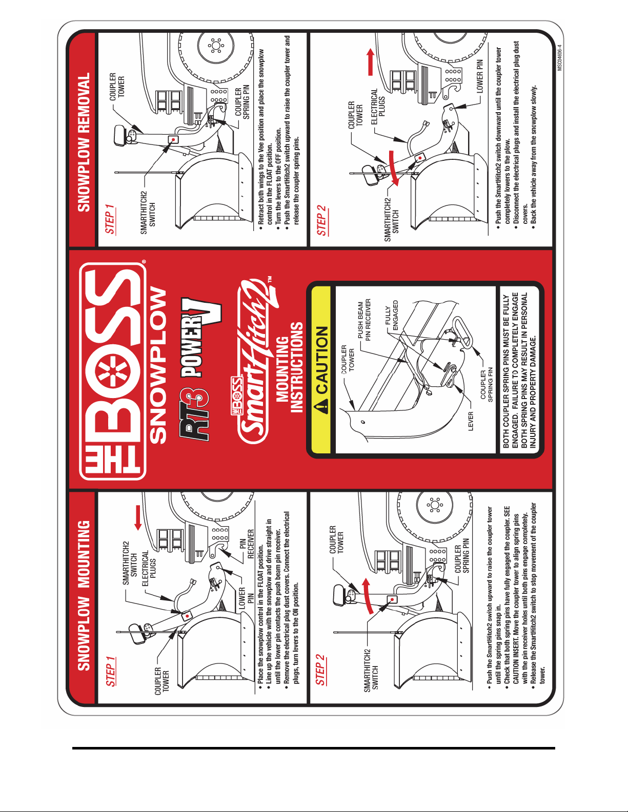
Snowplow Mounting Procedure
Figure 1. Mounting and Removal Instructions MSC04606
3
Snowplow Assembly Procedure
Snowplow Assembly
Procedure
Note: This manual is used for the installation of all V-
Plows. Part numbers and illustrations may vary.
1. Begin the assembly procedure by cutting down
each corner of the plow box so that each wall of
the box will lie flat on the floor. Lay the top of the
box flat on the floor. The top of the box can be
used as a mat and will help prevent scratching the
blade halves during installation.
2. Remove Left Blade Half (5) and Right Blade Half
(4) from the crate. Lay each blade half flat on the
box top, face down.
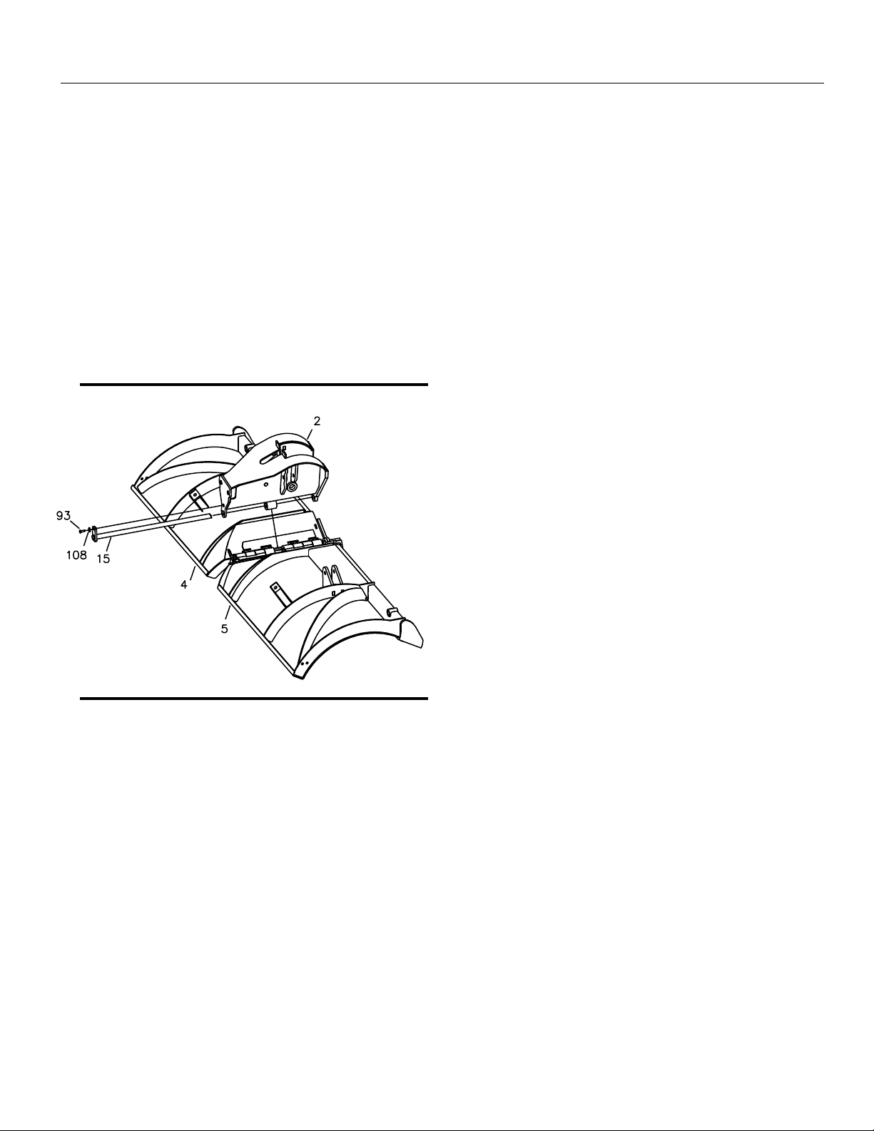
5. Secure Center Hinge Pin (15) to the top of Center
Section (2) using one HDW01771 3/8”-16 X 1 ¼”
Hex Head Cap Screw (93), and one HDW01718
3/8” Split Lock Washer (108).
Note: Plow shoes are optional. If added they should
be mounted flush with the bottom of the cutting edge
when the plow is mounted on the truck to be used for
plowing. When plowing on a solid level area (parking
lots, roads, and driveways) plow shoes can be raised
up to increase cutting edge contact on the plowed
surface. When plowing dirt, gravel, or grass plow
shoes should be lowered below the cutting edge
surface to prevent the plow from digging into the
plowed surface.
Figure 2. Blade Assembly Procedure. G10123
3. Align the center bushings on Left Blade Half (5)
with the center bushings on Right Blade Half (4).
Position CHA09716 Center Section (2) on top of
both blades so that all bushings align.
4. Insert MSC01507 Center Hinge Pin (15) through
Left Blade Half (5), Right Blade Half (4) and
Center Section (2).
4
Snowplow Assembly Procedure
Figure 3. Push Frame Assembly Procedure. G10122
6. Stand Blade Assembly and Center Section (2) on
the Cutting Edges with both wings forward in the
scoop position.
7. Remove the loose Horizontal Hinge Pin (102C)
that is inserted in the Center Section (2).
8. Slide TFR09708 Push Frame (3) into Center
Section (2). Re-insert Horizontal Hinge Pin (102C)
through Center Section (2) and Push Frame (3)
then secure with washer (102B) and nut (102A).
9. Attach Lift Cylinder (42) to Push Frame (3) with
HDW05563 Clevis Pin (104) and HDW05544
Hairpin Cotter (103).
10. Hook MSC04200 Spring Yoke (11) to the cross
rod inside Center Section (2).
11. Hook one end of MSC01509 Trip Spring (18) to
Spring Yoke (11). Attach the opposite end of Trip
Spring (18) to the rear angle of Push Frame (3)
using HDW05601 Eyebolts (98), 5/8” Flat
Washers (112) and 5/8” Self-Locking Nuts (111) .
Tighten Self-Locking Nuts (111) finger tight.
12. Attach HYD09731 Angle Cylinders (40) to Center
Section (2) using HDW01706 5/8”-11 X 4” Hex
Head Cap Screws (90) and HDW01709 5/8”-11
Self Locking Nuts (111). DO NOT over-tighten the
nuts.
Note: You should be able to slightly slide the cylinder
up and down on the bolt after it has been tightened.
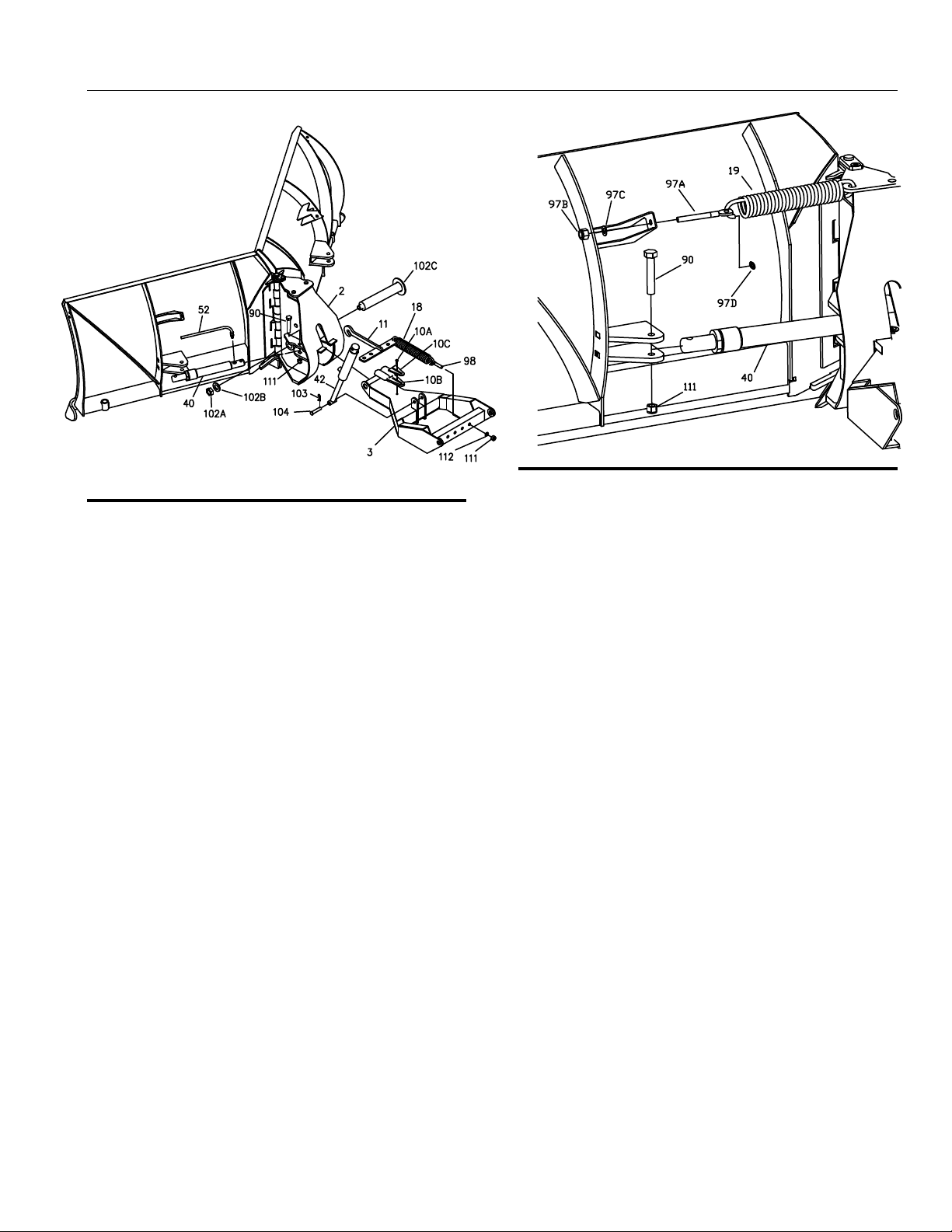
Figure 4. Angle Cylinder Installation. G10121
13. Pull both wings back into the ‘V’ position.
14. Hook one end of Return Spring (19) to the top
hole on Center Section (2). Hook the opposite end
of Return spring (19) to the blade spring mounting
bracket using ½” Spadebolt (97A), ½” Flat Washer
(97C), and ½” Self-Locking Nut (97B). Tighten
Spring (19) until there is a 1/32” space between
spring coils. Repeat this process for Return Spring
(19) on the opposite side of the plow.
15. Install one Push Nut Retainer (97D) on each end
of the Return Spring (19).
Note: Be sure Push Nut Retainer’s flanges are
pointing away from the Eyebolt and toward the open
end of the Return Spring.
16. Bolt the rod end of Angle Cylinder (40) to each
blade half using 5/8”-11 X 4” Hex Head Bolt (90)
and 5/8”-11 Self Locking Nuts (111). DO NOT
over tighten bolts. Repeat this process for Angle
Cylinder (40) on the opposite side of the plow.
Note: You should be able to slightly slide the cylinder
up and down on the bolt after it has been tightened.
5
Snowplow Assembly Procedure
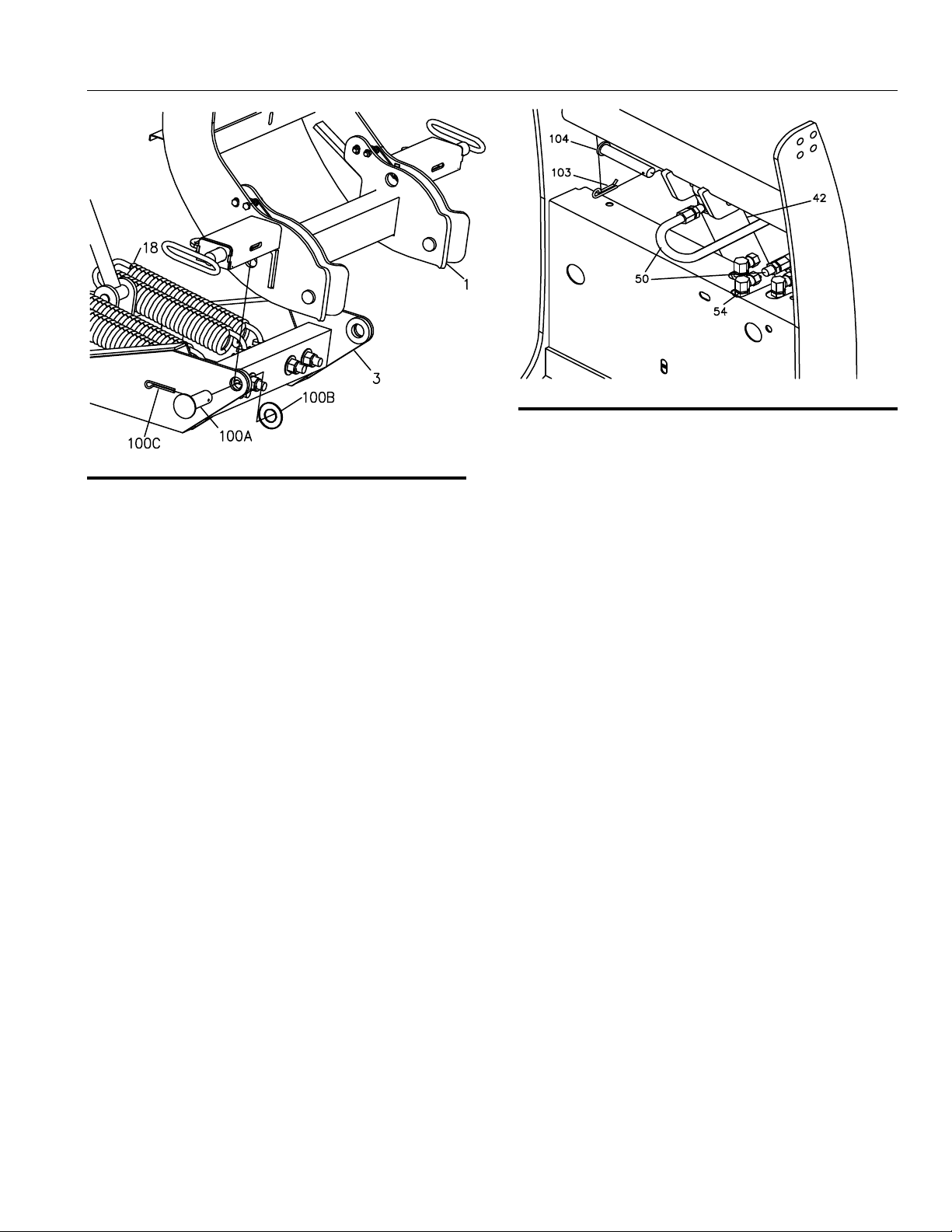
Figure 5. Coupler Assembly to Push Frame. G10119
17. Align pivot holes of Coupler Assembly (1) and
pivot holes of Push Frame (3).
18. Insert 1” X 2 ½” Pivot Pin (100A) through Coupler
Assembly (1) and Push Frame (3). Secure with 1”
Flat Washer (100B) and 3/16” Cotter Pin (100C).
Note: The 10’ V-Blade plow uses a 5/16” x 2” Bolt
and a 5/16” Locknut in place of 3/16” Cotter Pin
(100C).
19. Tighten the four Trip Springs (18) on Push Frame
(3) until there is a 1/32” space between each
spring coil.
Figure 6. Assembly of Lift Cylinder Hydraulics. G10138
20. Remove the plug from the top end of Lift Cylinder
(42).
21. Attach one end of Hydraulic Hose (50) to Lift
Cylinder (42). Be sure to apply thread sealant
compound to the pipe threads on Hydraulic Hose
(50). Tighten connection securely.
22. Attach the top end of Lift Cylinder (42) to Coupler
Assembly (1) using HDW05563 Clevis Pin (104)
and HDW05544 Hairpin Cotter (103).
23. Route Hydraulic Hose (50) in “S” shape and
connect the loose end to the rear Hydraulic Fitting
(54). Tighten connection securely.
6
Snowplow Assembly Procedure
Figure 7. Assembly of Hydraulic Connections. G10013
24. Attach one end of Hydraulic Hose (49) to the
lower port of Lift Cylinder (42). Attach the
opposite end of Hydraulic Hose (49) to the center
Hydraulic Fitting (54). Tighten connection
securely.
25. Apply thread sealant compound (do not use
Teflon Tape) to the threads of the 3/8” MNPT end
of HYD07042 Hydraulic Hose (52). Thread the
hose into the port on Angle Cylinder (40) and
tighten securely.
Note: Do not apply thread compound to the ¼” end of
the hose.
Note: Do not get thread compound on the end of the
hose since the compound will contaminate the
hydraulic system.
26. Attach the loose end of HYD07042 Hydraulic
Angle Hose (52) to the corresponding fitting on
the hydraulic manifold. Tighten all hydraulic
connections securely.
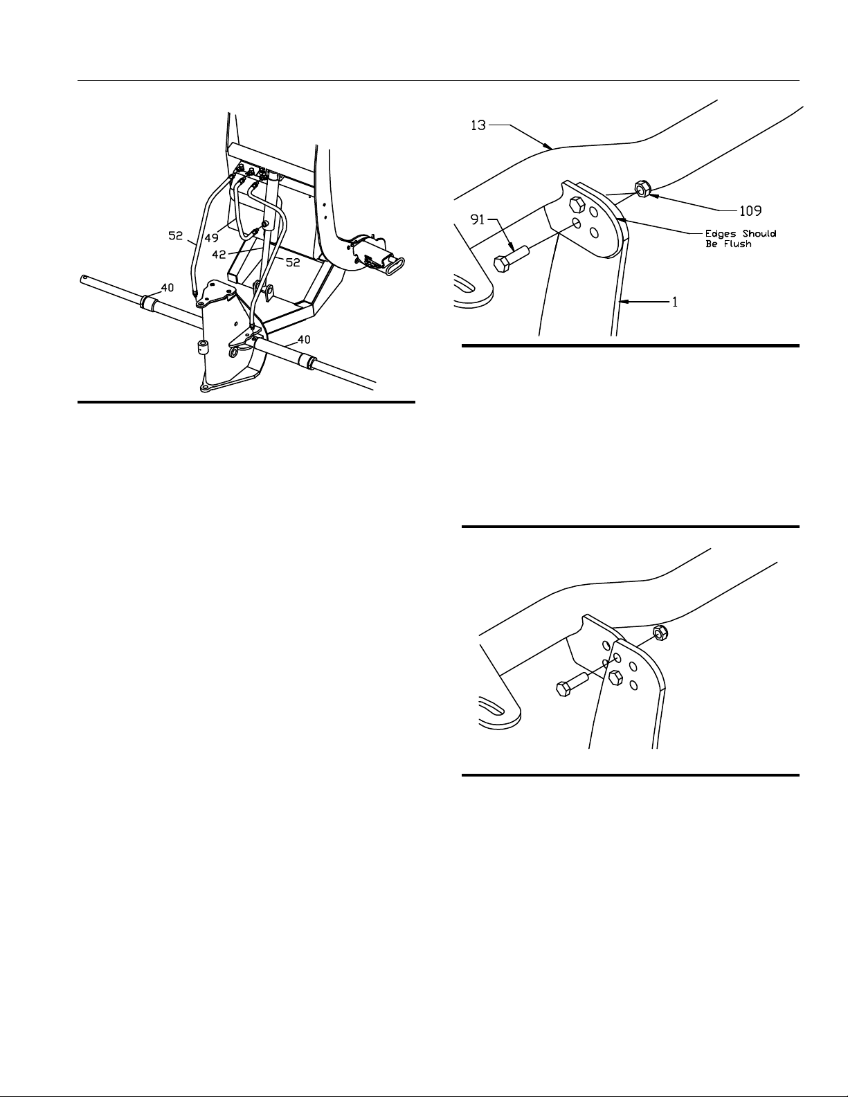
Figure 8. Light Bar Assembly. (Standard) G10132
27. Attach Light Bar (13) to the top of Coupler
Assembly (1) using two Hex Head Cap Screws
(91) and Hex Head Self Locking Nuts (109).
Note: The light bar should be positioned as close to
the Coupler Tower as possible. Only two holes will be
aligned for normal installations. Only two bolts per side
are needed to secure the light bar.
Figure 9. Light Bar Assembly Adjustment. G10131
Note: Figure 9 illustrates that the Coupler Assembly
and Light Bar have two sets of 1 inch adjustment holes
for mounting on different vehicles. These adjustment
holes may be needed in order to move the light bar
away from the vehicle’s hood.
7
Snowplow Assembly Procedure
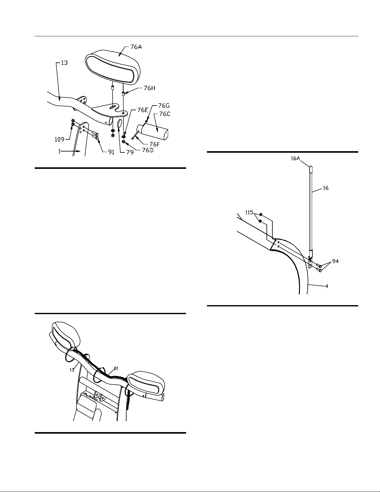
Figure 10. Headlight Mounting Assembly G10115
28. Insert Light Bar Seal (79) into the Light Bar and
seat it using the end of the Turn Signal (76C).
29. Attach Turn Signal (76C) into the end of Light Bar
(13) using one Machine Screw (76F) and Nut
(76G).
Note: Do not over tighten Machine Screw (76F).
30. Bolt Driver’s Side Headlight (76A) on to Light
Bar (13) using two bushings (76H), ½” Nuts
(76D) and ½” Star Washers (76E) as shown
above.
31. Repeat Steps 28 through 30 for Passenger’s
Side Headlight (76B) and Passenger’s Side
Turn Signal (76C).
33. Insert the unconnected ends of the Plow Wiring
Harness into the back of the coupler through
the rubber grommet.
34. Connect the Plow Side Wiring Harness to the
Hydraulic Valve Manifold as shown in Figure
26. HYD07044 with SmartHitch2TM Wiring
Diagram on page 18 of this manual.
Note: All wires need to be connected.
Note: The SmartHitch2TM switch is pre-wired from
the factory.
Figure 12. Assembly of Blade Guides. G10071
35. Attach Blade Guides (16) to Blade Assembly (4)
using Hex Head Cap Screws (94) and Self
Locking Nuts (115).
Figure 11. Secure Wiring Harness G10126
32. Secure Wiring Harness (61) to Light Bar (13)
as shown above.
8
Electrical System Wiring Procedure
Electrical System Wiring
Procedure
WARNING!
WARNING!
WARNING!WARNING!
Before starting any Electrical Wiring Procedure
make sure that the engine is not running and that
the engine has had sufficient time to cool down.
Failure to do so may result in serious bodily injury
or death.
WARNING!
WARNING!
WARNING!WARNING!
Before starting any Electrical Wiring Procedure
make sure to disconnect the battery. Failure to
do so may result in serious bodily injury or death.
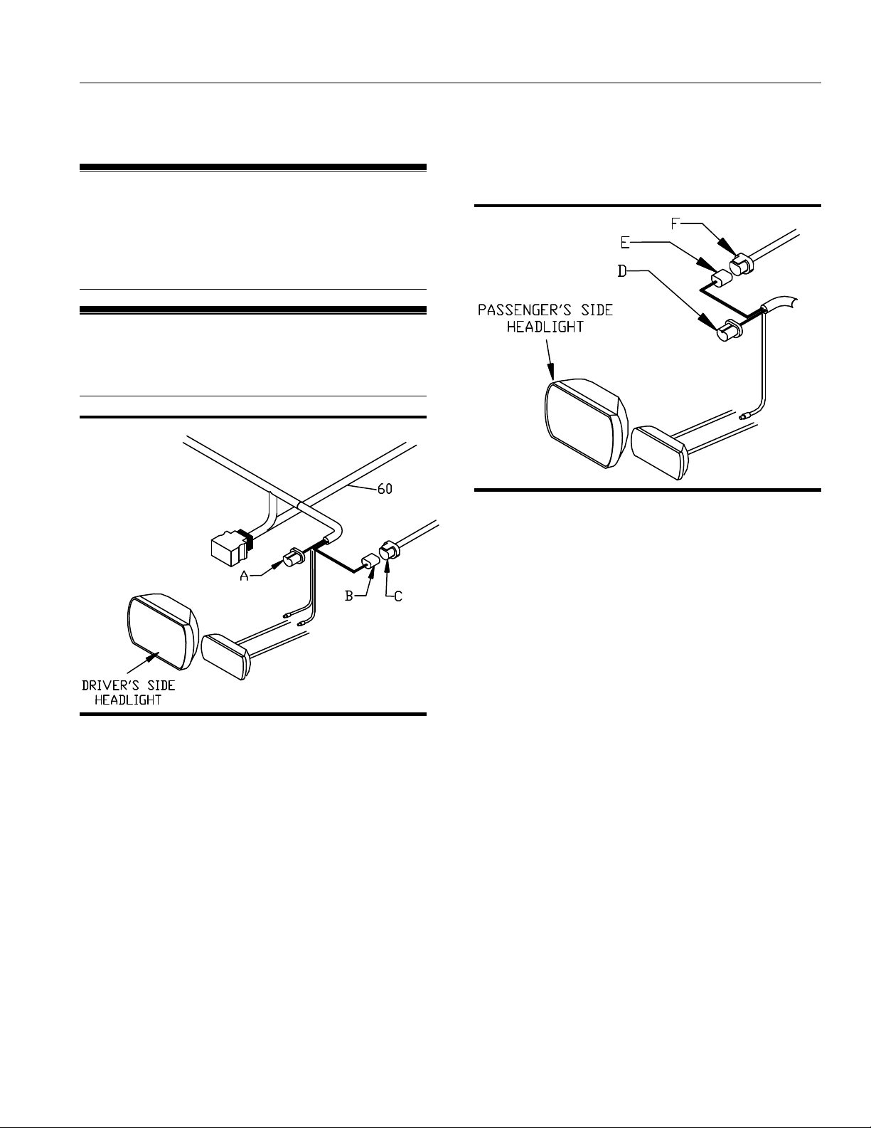
Figure 13. Driver’s Side Headlight G10140
Note: Dielectric grease should be applied to all
electrical connections.
1. Disconnect the driver’s side headlight connector
plug (C) from the back of the driver’s side vehicle
headlight.
2. Connect the Blue Sealed Beam Connector (A)
from Wiring Harness (60) into the back of the
driver’s side vehicle headlight.
3. Connect the Black Rubber Connector (B) from
Wiring Harness (60) into the OEM Wiring Harness
(C). OEM Wiring Harness (C) is the vehicle
connector that was unplugged from the back of
the headlight in Step 1.
Note: If your connectors do not match the connectors
on the wiring harness or you have a four-headlight
system a Headlight Adapter Kit will be needed. If you
are installing a Headlight Adapter Kit, See “Headlight
Adapter Installation Procedure” located in this manual.
Figure 14. Passenger’s Side Headlight G10141
4. Disconnect the passenger’s side OEM Wiring
Harness (F) from the back of the passenger’s side
vehicle headlight.
5. Connect the Blue Sealed Beam Connector (D)
from Wiring Harness (60) into the back of the
passenger’s side vehicle headlight.
6. Connect the Black Rubber Connector (E) from
Wiring Harness (60) into the OEM Wiring Harness
(F). OEM Wiring Harness (F) is the vehicle
connector that was unplugged from the back of
the headlight in Step 4.
9
Electrical System Wiring Procedure
NOTICE
Before splicing into any electrical circuit, identify
the circuit with a test lamp. Failure to test circuits
may result in vehicle damage.
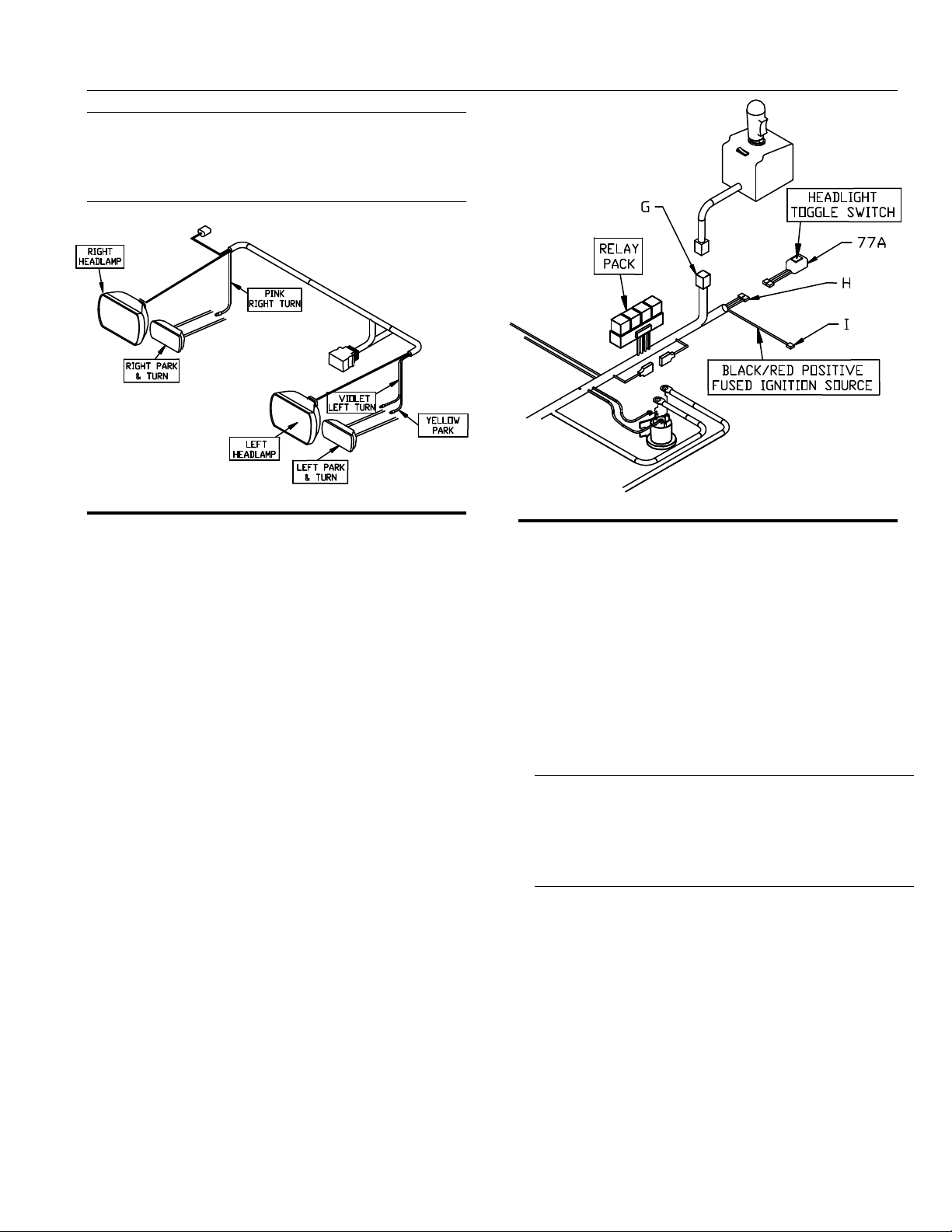
Figure 15. Connecting Park and Turn G10143
Note: Some trucks require a turn signal relay kit.
7. Connect the PINK wire from Wiring Harness (60)
to the passenger’s side turn signal wire. Use the
splice connector provided to you in the hardware
kit.
8. Connect the VIOLET wire from Wiring Harness
(60) to the driver’s side turn signal wire. Use the
splice connector provided to you in the hardware
kit.
9. Connect the YELLOW wire from Wiring Harness
(60) to the driver’s side park light wire. Use the
splice connector provided to you in the hardware
kit.
Note: Be sure that the firewall is clear of obstructions
before drilling in Step 10.
10. Drill a 1-1/4" diameter hole through the firewall.
The hole should be located on the driver’s side, in
an easily accessible area.
Figure 16. Internal Cab Wires G10144
11. Pull the two BLACK wires (H), BLACK/RED wire
(I), and the 9 Pin Molex connector (G) from the
engine compartment into the cab through the
1-1/4” diameter hole in the firewall.
12. Install MSC03761 Split Rubber Grommet (Not
Shown) into the hole that was cut in the firewall.
13. Connect the Two Tab Connectors (H) to
MSC04747 Headlight Toggle Switch (77A) as
illustrated in the figure above.
NOTICE
Position the switch where it will not interfere
with driver’s ability to see and where it will not
affect the driver’s ability to operate the motor
vehicle.
14. Choose an area of the vehicle’s dashboard for the
light toggle switch to be mounted. Clean the area
thoroughly. Allow the area to dry completely.
15. Remove the adhesive backing and apply the
switch to the clean area of the dashboard. Apply
pressure for 30 seconds.
10
 Loading...