

Page 1
Owner’s Manual
* This device contains demo data (Phrase Memory 90–99).
Once you delete these, they cannot be recovered. Please back them up as described in “Backing up to your computer” (p. 37).
* With the factory settings, the RC-300’s power will automatically be switched o 10 hours after you stop playing or operating the unit.
If you want to have the power remain on all the time, change the “Auto O” setting to “OFF” as described on “Auto O Settings” (p. 33).
The settings you were editing will be lost when the power is turned o. If you want to keep your settings, you must save your settings
before turning the power o.
Main Features
Welcome to the Loop Station!
The RC-300 is a pedal-type recorder that lets you record audio phrases from your guitar or vocal etc., and play them back by operating the pedal.
You can create a wide variety of performances by layering sound while you record and carry out play back in real time.
• You can save a maximum of approximately 3 hours of stereo sound (*total for all phrase memory) and up to 99 phrase memories.
• Three-track recording allows a wide range of performance possibilities.
• You can input audio in stereo.
• In addition to guitar (INST) input, a MIC input and AUX IN jacks are also provided. You can connect a microphone and loop-record your voice, or
record sound from your digital audio player.
• You can easily connect the RC-300 to your computer using a single USB cable. Once connected, you gain a digital audio connection with your
computer and the ability to export/import loop phrases (WAV les) (p. 36).
• You can apply an eect that is synchronized with the tempo of tracks while you play it back. You can use the EXP (expression) pedal to control
eects (p. 28).
• Two RC-300 units can be synchronized after connecting them together using a MIDI cable (p. 39).
Page 2

Contents
Main Features ...................................................1
Panel Descriptions ...............................................4
Top Panel .......................................................4
Rear Panel Connections .........................................6
Turning On the Power ...........................................7
Overview of the RC-300 ..........................................8
Basic Editing Procedure .........................................9
Basic Operation ................................................10
Selecting a Phrase Memory. . . . . . . . . . . . . . . . . . . . . . . . . . . . . . . . . . . . .10
Recording .....................................................10
Overdubbing ..................................................11
Stop ...........................................................11
Loop Playback .................................................11
Cancelling a Recording/Overdubbing (Undo/Redo/Track Clear) .12
Example of Actual Loop Recording .............................12
Recording on a Single Track ..............................13
Recording on Multiple Tracks .............................13
Saving a Phrase Memory ........................................14
Saving a Phrase Memory (Write) ................................14
Copying a Track from Another Phrase Memory (Track Copy) .....14
Exchanging Phrase Memories ..................................15
Deleting a Phrase Memory (Initialize) ...........................15
Settings for Each Track ..........................................16
Overview of the Playback Settings ..............................16
Loop Playback Settings (Play Mode) ......................16
Aligning the Beginning of Loop Playback (Loop Sync) .....16
Synchronizing the Tempo ( Tempo Sync) ..................16
Specifying the Number of Measures in a Track (Measure) ..16
Playing Only a Single Track (Single Track Play) .............16
Settings for Each Track .........................................17
Specifying How the Track Will Play (Play Mode) ............17
Playing a Track Backward (Reverse) .......................17
Specifying the Number of Measures in a Track (Measure) ..17
Specifying How the Track Will Stop (Stop Mode) ...........17
Adjusting the playback level of the Tracks (Play Level) .....17
Adjusting the recording level of the Tracks (Recording
Level) ....................................................18
Adjusting the Positioning of the Track’s Sound (Pan) .......18
Aligning the Beginning of Loop Playback (Loop Sync) .....18
Synchronizing the Tempo ( Tempo Sync) ..................18
Assigning a Track’s Output Jacks (Output Select) ..........19
Phrase Memory Settings ........................................20
Naming Phrase Memories (Memory Names) ..............20
Adjusting the Phrase Memory Volume (Memory Level) ....20
Setting the Output Jacks for the Sounds Being Input
(Input Output Select) .....................................20
Synchronizing the Tempo of Two RC-300 Units (MIDI Sync) 21
Setting the Overdubbing Method (Overdubbing Mode) ...21
Switching Between Stereo and Mono (Recording Mode) ..21
Specifying a Phrase Memory’s Tempo .....................21
Adjusting the Time Used to Fade Out (Fade-Out Time) .....21
Simultaneously Starting Recording When Sounds are
Input (Auto Recording) ...................................22
Playing Only a Single Track (Single Track Play) .............22
Specifying how the Track will Switch (Track Change Mode) 22
Adjusting the Reverb Depth (Reverb Level) ...............22
Assigning the Function of Pedals and External Controllers
(Assign) ........................................................23
Enabling Assignments 1–8 (Assign Switch) ................23
Specifying the Assignment Target (Assign Target) .........23
Specifying the Target Range (Target Range) ...............23
Specifying the Controller (Assign Source) .................23
Specifying the Type of Operation (Source Mode) ..........24
Connecting to External Pedals ............................24
About Rhythm ..................................................25
Sounding a Rhythm ............................................25
Rhythm Settings ...............................................25
Selecting the Rhythm Sound (Rhythm Pattern) ............25
Selecting the Beat (Time Signature) for the Rhythm
Sound (Beat) .............................................25
Playing a Count-In When Recording (Recording Count-In) .26
Playing a Count-In for Playback (Playback Count-In) .......26
Stopping the Rhythm When the First Recording Ends
(Rhythm Stop) ...........................................26
Adjusting the Volume of the Rhythm Sound (Rhythm
Level) ....................................................26
Setting the Output Jacks for the Rhythm Sound
(Rhythm Output Select) ..................................26
Using LOOP FX .................................................28
Turning LOOP FX On/O .......................................28
LOOP FX Settings ..............................................28
Specifying What LOOP FX Will Apply To (LOOP FX Target) ..28
Selecting the LOOP FX Category and Type (LOOP FX
Category, LOOP FX Type) .................................29
Before using this unit, carefully read the sections entitled: “USING THE UNIT SAFELY” (p. 44) and “IMPORTANT NOTES” (p. 45). These sections provide important information
concerning the proper operation of the unit.
Additionally, in order to feel assured that you have gained a good grasp of every feature provided by your new unit, Owner’s Manual should be read in its entirety. The manual
should be saved and kept on hand as a convenient reference.
2
Page 3

Contents
System Settings (Settings for the Entire RC-300) ..................32
Adjusting the Display’s Brightness (LCD Contrast) .........32
Specifying the Operation of the [LOOP FX] Pedal ..........32
Limiting the Phrase Memories That can be Switched
(Phrase Memory Extent) ..................................32
Setting the Knob/Slider Functions (Knob Mode) ...........32
Adjusting the Auto Recording Sensitivity (Trigger Level) ...33
Changing the Switching Order of Recording g
Overdubbing g Playback (REC Pedal Action) ..............33
Using the Same Output Jacks for All Phrase Memories
(Input/Track 1, 2, 3/Rhythm Output) .......................33
Adjusting the Output Level of the SUB OUTPUT Jacks
(SUB OUTPUT Level) ......................................33
Auto O Settings .........................................33
MIDI-Related Settings ..........................................34
MIDI Receive Channel ....................................34
MIDI Omni Mode .........................................34
MIDI Transmit Channel ...................................34
Synchronizing the Tempo of Two RC-300 Units (MIDI Sync) .34
MIDI Program Change Out ................................34
USB-Related Settings ...........................................35
Adjusting the USB Audio Input Volume (USB In Level) .....35
Adjusting the USB Audio Output Volume (USB Out Level) ..35
Setting the Output Jacks for the USB Audio (USB Output
Select) ...................................................35
Setting the USB Mode (USB Mode) ........................35
Adjusting the Expression Pedal ..................................40
Troubleshooting ................................................41
Error Message List ..............................................42
Specications ...................................................43
USING THE UNIT SAFELY .........................................44
IMPORTANT NOTES .............................................45
Index ...........................................................46
Overview Basic Operation Saving Track
Phrase Memory
Connecting to Your Computer via USB ...........................36
Installing the USB driver ........................................36
Setting the USB Mode (USB Mode) ..............................36
Connecting the RC-300 to a Computer ..........................36
USB Function Settings ..........................................36
Using USB to Exchange Files with Your Computer (USB Mass
Storage) .......................................................36
Connecting an External MIDI Device or Another RC-300 Unit ......38
About MIDI Connectors ........................................38
MIDI settings ...................................................38
Controlling an External MIDI Device from the RC-300 ......38
Controlling the RC-300 from an External MIDI Device ......39
Connecting Two RC-300 Units ..................................39
Restoring the Factory Settings (Factory Reset) ....................40
Rhythm LOOP FX System Settings USB MIDI Appendix
3
Page 4
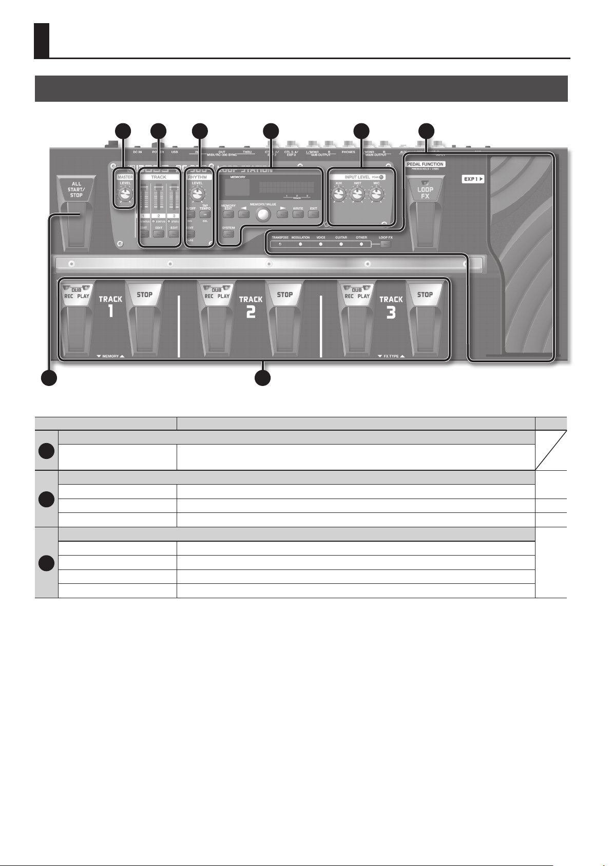
Panel Descriptions
Top Panel
1 2 3 4 5 6
87
Name Explanation Page
MASTER
1
MASTER [LEVEL] knob
TRACK
TRACK [1]–[3] sliders Adjust the volume of the tracks.
2
STATUS indicators Lights when there is data in a track. p. 10
TRACK [EDIT] buttons Used to make settings for each track. p. 17
RHYTHM
RHYTHM [LEVEL] knob This adjusts the volume level of the rhythm sound.
RHYTHM [ON/OFF] button This button turns the rhythm sound on/o.
3
[TAP TEMPO] button Press this button at the desired timing to set the tempo of the rhythm (phrase memory tempo: p. 21).
RHYTHM [EDIT] button Press this button to make rhythm settings.
Adjusts the volume of the entire RC-300 (MAIN OUTPUT jacks).
* The MASTER [LEVEL] knob does not aect the SUB OUTPUT jacks or USB audio.
p. 17
p. 25
4
Page 5
Panel Descriptions
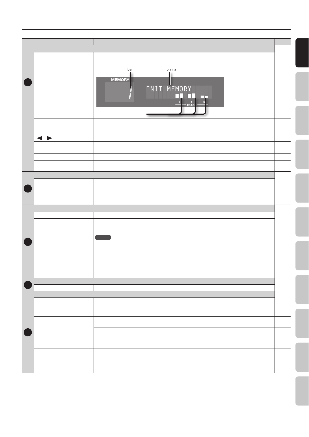
INIT MEMORY
Name Explanation Page
MEMORY
This indicates the current phrase memory number, or various other information.
The following information is shown in the Play screen, which is the RC-300’s main screen.
Phrase memory number
Phrase memory name
Basic Operation Saving Track
4
Display
Level meters for each track
[MEMORY EDIT] button Press this button to make phrase memory settings. p. 20
[SYSTEM] button Press this button to edit the system settings. p. 32
] /[ ] buttons
[
[MEMORY/VALUE] knob
[WRITE] button Press this to save the phrase memory. p. 14
[EXIT] button
INPUT LEVEL
[AUX] knob
[INST] knob
5
[MIC] knob
PEAK indicator
LOOP FX
[LOOP FX] button Use this button to edit the LOOP FX settings.
LOOP FX indicators The indicator for the category of the currently selected LOOP FX will light.
Use these buttons to select the parameter shown in the display. p. 9
In the Play screen, use this knob to select the desired phrase memory.
In edit screens, use this knob to edit the value.
Press this button to exit an edit screen and return to the Play screen. You can also press this button to cancel an
operation.
Adjusts the input level from the INPUT (AUX, INST, MIC) jacks.
Adjust each [INPUT LEVEL] knob so that the PEAK indicator lights only occasionally, when the level of the input is at its
highest.
Turns LOOP FX on/o.
p. 10
p. 10
p. 9
p. 9
Phrase Memory
p. 6
Rhythm LOOP FX System Settings USB MIDI AppendixOverview
6
MEMO
[LOOP FX] pedal
[EXP 1] pedal
(Expression 1 pedal)
ALL START/STOP
7
[ALL START/STOP] pedal Plays/stops all tracks simultaneously.
TRACK 1–3 pedals
REC (red) indicators Lights during recording.
PLAY (green) indicators
[REC/DUB/PLAY] pedals
8
[STOP] pedals
If you hold down the [LOOP FX] pedal for two seconds or longer, you will then be able to use the TRACK 1 pedal
to select a phrase memory, and use the TRACK 3 pedal to select the LOOP FX type. For details, refer to “Using the
pedals to select phrase memories or LOOP FX (Pedal Function mode)” (p. 10).
[LOOP FX] on/o is not the only function that can be assigned to the [LOOP FX] pedal (p. 23).
Controls the LOOP FX according to the depth to which you depress the pedal.
You can assign the operation of the [EXP 1] pedal independently for each phrase memory. For details, refer to
“Assigning the Function of Pedals and External Controllers (Assign)” (p. 23).
Lights during playback.
During overdubbing, both the REC (red) indicator and the PLAY (green) indicator will light.
Switches the unit between
recording/overdubbing/playback
Undo/Redo
Stop Stops the track currently being recording/overdubbing/playback. p. 11
Tap tempo
Track clear To clear the track, hold down the [STOP] pedal for at least two seconds. p. 12
If the track is empty: recording g overdubbing g playback
If the track contains data: playback g overdubbing
During playback or overdubbing, hold down the [REC/DUB/PLAY] pedal for two
or more seconds to undo (cancel the recording or the most recent overdubbing).
To carry out a redo, once again depress the pedal for two or more seconds (the
sound that was eliminated will be restored).
Press the [STOP] pedal repeatedly to set the phrase memory tempo to the timing
at which you pressed it.
p. 28
p. 11
p. 10
p. 10
p. 12
p. 21
5
Page 6
Panel Descriptions
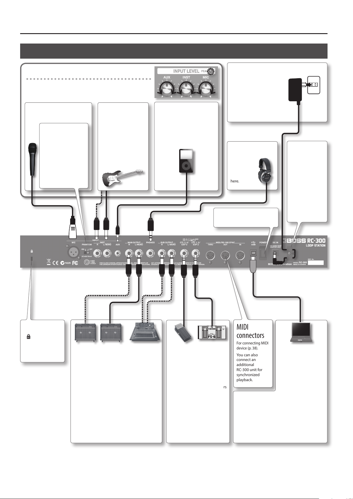
Rear Panel Connections
Adjusting the input level
Adjust each [INPUT LEVEL] knob so that the PEAK indicator lights only
occasionally, when the level of the input is at its highest.
INPUT MIC jack
Connect your microphone here.
[PHANTOM]
switch setting
If you’re using
a condenser
microphone, choose
the “ON” setting. If
you’re using a dynamic
microphone, choose
the “OFF” setting.
* Ordinarily, this is set
to “OFF.”
INPUT INST jacks
Connect your guitar, bass,
or eects unit to these
jacks.
Use the INPUT L jack
and INPUT R jack when
connecting a stereooutput eects unit. Use
only the INPUT L jack if
you’re using a monaural
source.
INPUT AUX jack
Use a stereo mini-plug cable to
connect your audio player here.
DC IN jack
Connect the included AC
adaptor here.
* Use only the included
AC adaptor. Using any
other adaptor may
cause overheating and
malfunction.
PHONES jack
Connect
a set of
headphones
(sold
separately)
here.
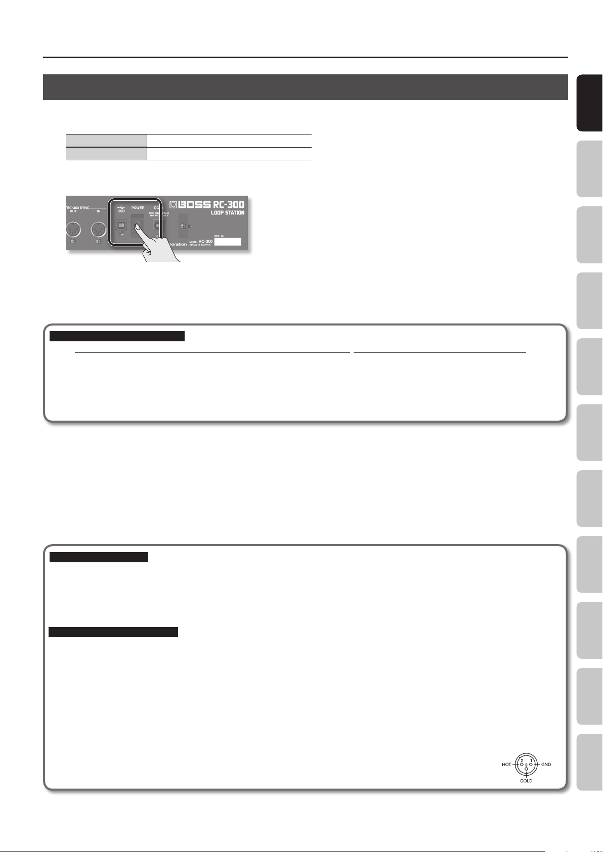
[POWER] switch
This turns the power on/o (p. 7).
To prevent the
inadvertent
disruption of
power to your
unit (should the
plug be pulled out
accidentally), and
to avoid applying
undue stress to
the DC IN jack,
anchor the power
cord using the
cord hook, as
shown in the
illustration.
Security slot
)
(
http://www.
kensington.com/
6
MAIN OUTPUT jacks
Connect these jacks to your amp or monitor
speakers.
If your system is monaural, use only the OUTPUT
L jack. Sound that was input in stereo will also be
output monaurally.
SUB OUTPUT jacks
Connect these jacks to your mixer or other equipment. The sound of a specic track, the audio
input, or sound from a computer connected via
USB can be output from the SUB OUTPUT jacks
independently of the MAIN OUTPUT jacks (p.
33).
CTL 1, 2/EXP 2 jack
CTL 3, 4/EXP 3 jack
You can connect EXP pedals
(EV-5, etc. ; sold separately) or
foot switches (FS-5U, FS-6; sold
separately) here, and use them
to control a variety of parameters
(p. 24).
MIDI
connectors
For connecting MIDI
device (p. 38).
You can also
connect an
additional
RC-300 unit for
synchronized
playback.
your computer through the RC-300 via USB audio
(p. 36).
About USB cap
If you want to connect a USB cable, detach the
USB cap that covers the USB connector. Leave the
USB cap in place when you’re not using the USB
connector.
USB connector
You can use a
commercially available
USB cable to connect the
RC-300 to your computer,
and use the computer
to read/write RC-300
tracks (WAV les). You
can play sounds from
Page 7
Panel Descriptions
Turning On the Power
Once the connections have been completed, turn on power to your various devices in the order specied. By turning on devices in the wrong order,
you risk causing malfunction and/or damage to speakers and other devices.
When powering up Turn on the power to your amp last.
When powering down Turn o the power to your amp rst.
1. Turn the [POWER] switch ON.
* This unit is equipped with a protection circuit. A brief interval (a few seconds) after power up is required before the unit will operate normally.
Also, for a short period of time, phantom power won’t be switched on for the INPUT MIC connector.
* Before switching the power on/o, always be sure to turn the volume down. Even with the volume turned down, you might hear some sound
when switching the power on/o. However, this is normal and does not indicate a malfunction.
Caution when turning o the power
While the RC-300 is in the following states, you must never turn o the power. Doing so may cause all the saved data to be lost.
• While recording/overdubbing/playing back
• While undoing/redoing
• While switching between phrase memories
• While the following messages are displayed
“Now work ing..”, “Now writing...”, “Now copying..”, “Exchanging..”, “Initializing...”
Basic Operation Saving Track
Phrase Memory
Rhythm LOOP FX System Settings USB MIDI AppendixOverview
Caution when connecting
* To prevent malfunction and/or damage to speakers or other devices, always turn down the volume, and turn o the power on all devices before
making any connections.
* Before connecting or disconnecting any connection cables, be sure all the volume controls in your system are set to minimum.
* When connection cables with resistors are used, the volume level of equipment connected to the inputs (AUX/INST/MIC jacks) may be low. If this
happens, use connection cables that do not contain resistors.
Caution when using a microphone
* Howling could be produced depending on the location of microphones relative to speakers. This can be remedied by:
• Changing the orientation of the microphone(s).
• Relocating microphone(s) at a greater distance from speakers.
• Lowering volume levels.
* If the amp and microphone are close together, the sound played back from the amp may be picked up by the microphone. If you record or overdub
in such a state, the amp playback picked up by the microphone will also be recorded. You should separate the amp and microphone so that the
playback from the amp is not picked up by the microphone.
* Always turn the phantom power o when connecting any device other than condenser microphones that require phantom power. You risk causing
damage if you mistakenly supply phantom power to dynamic microphones, audio playback devices, or other devices that don’t require such power.
Be sure to check the specications of any microphone you intend to use by referring to the manual that came with it.
(This instrument’s phantom power: 48 V DC, 10 mA Max)
* This instrument is equipped with balanced (XLR) type jacks. Wiring diagrams for these jacks are shown below. Make connections
after rst checking the wiring diagrams of other equipment you intend to connect.
7
Page 8
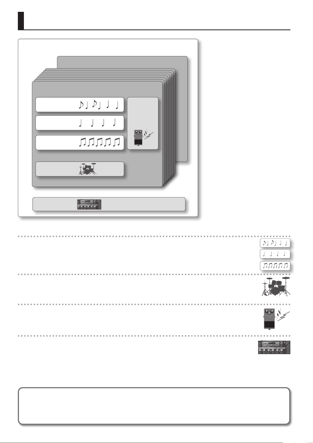
Overview of the RC-300
How the RC-300 is organized
Phrase Memory 99
Phrase Memory 1
Track 1
Track 2
Track 3
Rhythm
System Settings
LOOP FX
What are tracks (p. 16) and phrase memories (p. 20)?
The RC-300 provides three “tracks” that are used to record and play back the sound of an instrument or microphone.
These three tracks combined form what is called a “phrase memory.” Up to 99 phrase memories can be stored.
What is a rhythm? (p. 25)
In addition to the three tracks, the RC-300 can also play a “rhythm.” You can record while listening to a rhythm at the tempo you
specify.
What is the LOOP FX? (p. 28)
You can apply an eect to the sound of each track. This eect is called a “LOOP FX.”
What are system settings? (p. 32)
Settings that apply to the entire RC-300, such as those for the contrast of the display and the auto o function, are called “system
settings.”
Saving your data (p. 14)
If you select a dierent phrase memory or turn o the power after recording or editing the settings, the recorded content or edited settings will
be lost. If you want to preserve a phrase memory, you must save it as described in “Saving a Phrase Memory (Write)” (p. 14).
However, system settings are saved as soon as you edit them.
8
Page 9
Overview of the RC-300
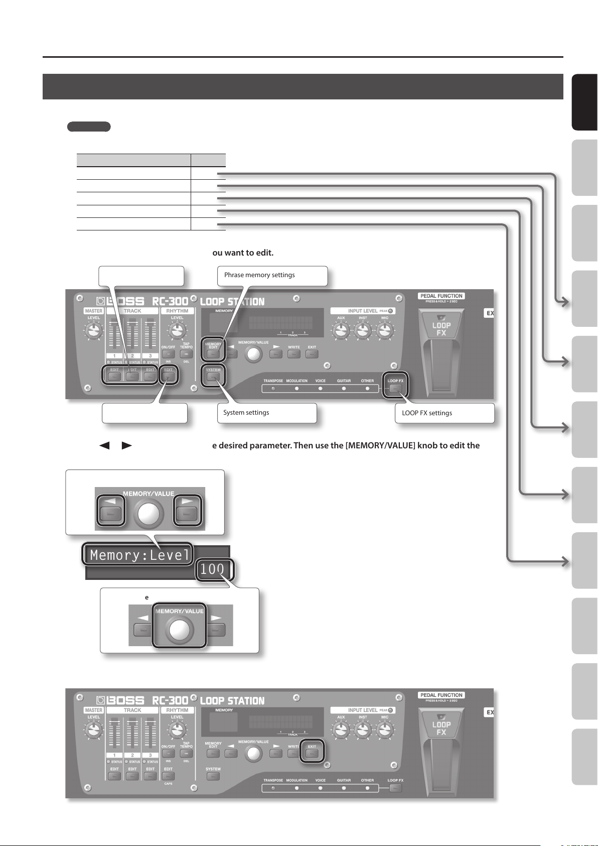
Basic Editing Procedure
Editing the RC-300’s settings is a simple and consistent procedure. Before you continue, please take a moment to learn the basic editing procedures.
Reference
For details on each item, refer to the pages listed below.
Item Page
Settings for each track p. 16
Phrase memory settings p. 20
Rhythm settings p. 25
LOOP FX settings p. 28
System settings p. 32
1. Press the button for the type of item you want to edit.
Settings for each track Phrase memory settings
Basic Operation Saving Track
Phrase Memory
Rhythm settings System settings
LOOP FX settings
2. Use the [ ] /[ ] buttons to select the desired parameter. Then use the [MEMORY/VALUE] knob to edit the
value of that parameter.
Select a parameter
Memory:Level
100
Edit the value
3. Press the [EXIT] button to return to the play screen.
Rhythm LOOP FX System Settings USB MIDI AppendixOverview
9
Page 10
Basic Operation
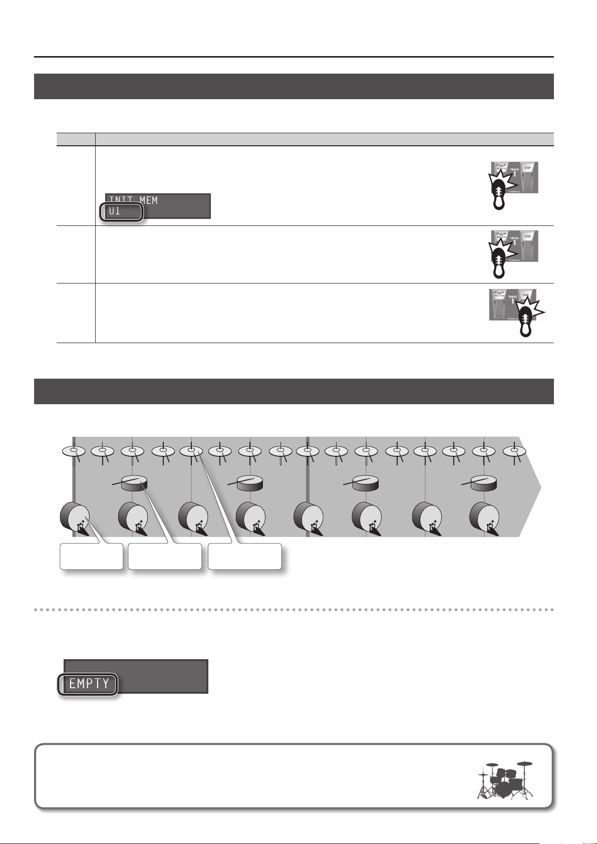
INIT MEMORY
EMPTY
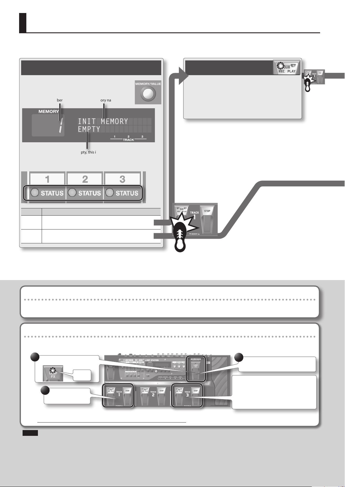
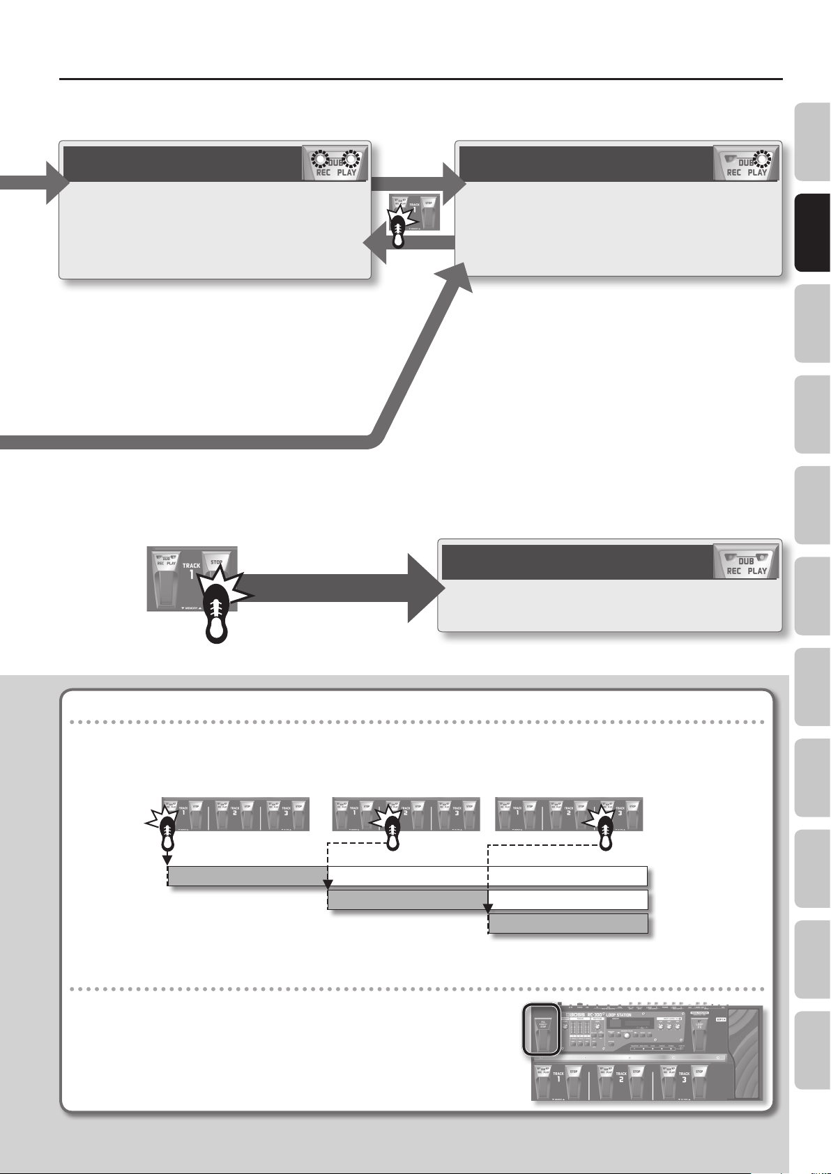
To perform recording, overdubbing, and playback, press the [REC/DUB/PLAY ] pedal as shown in the diagram.
Selecting a Phrase Memory
Use the [MEMORY/VALUE] knob to select a phrase
memory (1–99).
Phrase memory number
If all tracks are empty, this indicates “EMPTY”
The STATUS indicators show whether each track contains data.
Indicator Explanation
Unlit
Lit
Empty track
Press the [REC/DUB/PLAY] pedal to start recording
Data exists
Press the [REC/DUB/PLAY] pedal to start playback
Phrase memory name
Recording
Record your guitar or bass performance, or the
sound from an audio player connected to the
AUX IN jack.
Pressing the [REC/DUB/PLAY] pedal switches the
unit to overdubbing.
• Auto recording (p. 22) lets you start recording the moment you begin
performing.
• You can also record along with rhythm sounds (p. 25).
• Pressing the [REC/DUB/PLAY] pedal will normally switch the RC-300’s
state in the order of
recording g overdubbing g playback.
However, if desired, you can change this order to
recording g playback g overdubbing (p. 33).
• When shipped from the factory, phrase memories 90–99 contain demo
data.
“Recording” versus “Overdubbing”
In this manual, we refer to the act of recording to an empty track for the rst time as “recording.” Any subsequent recordings that are made,
which are added on top of the existing recording, we refer to as “overdubbing.”
Using the pedals to select phrase memories or LOOP FX (Pedal Function mode)
Hold down the [LOOP FX] pedal for two seconds or longer to put the RC-300 in Pedal Function mode; now you can use the TRACK 1 pedals to
select phrase memories, and the TRACK 3 pedals to select the LOOP FX.
1
Hold for 2 seconds or longer
Blink
2
Select a phrase
memory
* If you select a dierent phrase memory, any unsaved content will be lost. For details on saving a phrase memory, refer to p. 14.
3
Press once again to return to normal
mode
In Pedal Function mode, you can also use the
TRACK 3 pedals to select the LOOP FX type
(p. 29).
* The current phrase memory number selected
by the TRACK 1 pedals will be cancelled.
NOTE
* The minimum recording time for a track is approximately 1.5 seconds. If you press the pedal within approximately 1.5 seconds after you start
recording, recording will continue until the track is at least approximately 1.5 seconds long.
* The maximum recording time is approximately 3 hours (total for all phrase memories). When the maximum recording time is exceeded, the
display will show “Memory Full!” to indicate that internal memory is full, and recording or overdubbing may end before you intended. If this
occurs, delete unneeded phrase memories (p. 15) and then try the operation again.
10
10
Page 11
Basic Operation
Overview Saving Track
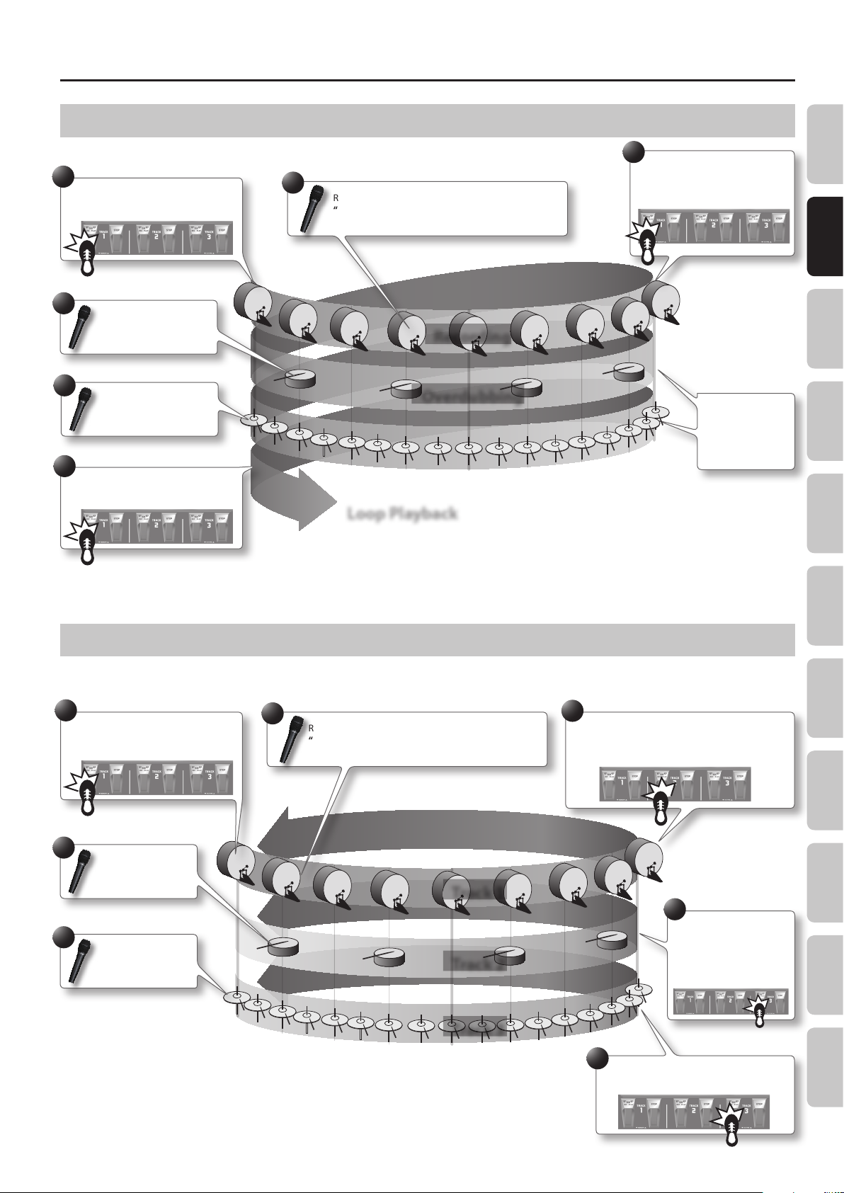
Overdubbing
Layer your performances while the track plays as a loop.
Pressing the [REC/DUB/PLAY] pedal switches the unit to
playback.
• You can Undo and Redo (p. 12).
Press the [STOP] pedal
Loop Playback
Play back track as loops.
Pressing the [REC/DUB/PLAY] pedal switches the unit to
overdubbing.
Stop
Regardless of the timing, pressing the [STOP] pedal will stop
the track.
Phrase Memory
Rhythm LOOP FX System Settings USB MIDI AppendixBasic Operation
Available tracks for recording/overdubbing
Recording/overdubbing can be performed on only one track at a time.
For example, if all tracks in the phrase memory are empty, and you’re recording track 1, pressing the track 2 [REC/DUB/PLAY] pedal will switch
track 1 to playback, and recording will occur on track 2.
Track 3 pedalTrack 2 pedalTrack 1 pedal
Track 1
Track 2
Track 3
Recording
Playback
Recording
Playback
Recording
Starting all tracks simultaneously (All Start)
• Press the [ALL START/STOP] pedal when you want all tracks to start playing
simultaneously.
• Likewise, press the [ALL START/STOP] pedal when you want all tracks to stop
simultaneously.
• If all tracks are empty, nothing will happen when you press the [ALL START/STOP]
pedal.
11
11
Page 12
Basic Operation
Cancelling a Recording/Overdubbing (Undo/Redo/Track Clear)
You can undo/redo by holding down the [REC/DUB/PLAY] pedal for two seconds or longer. You can clear the track by holding down the [STOP] pedal
for two seconds or longer.
Operation Explanation
If you hold down the [REC/DUB/PLAY] pedal for two seconds or longer during recording, overdubbing or playback, the recording or
the most recent overdub on each track will be cancelled.
“U1,” “U2,” or “U3” will be displayed at the lower left of the screen to indicate the track number for which the Undo has been carried
Undo
Redo
Track
clear
out. A Redo can be carried out with respect to a track for which this indication appears.
INIT MEMORY
U1
If you want to restore the cancelled sound, hold down the [REC/DUB/PLAY] pedal for at least two seconds while playback once
again.
* Redo is only available for overdubbing.
Holding down the [STOP] pedal for two seconds or longer will clear the track. (This Clear operation is temporary; the track saved in
the phrase memory will not be erased.)
If you want to restore the contents of a track that has been cleared, reselect the phrase memory. However, if a track has not been
saved, you won’t be able to restore its contents.
Example of Actual Loop Recording
How let’s try loop-recording the following simple 8-beat phrase of vocal percussion (using your voice to imitate the sounds of a drum set) via a
microphone.
Bass drum
“Dun!”
Preparations
1. Connect your microphone, and adjust the input level (p. 6).
2. Select an empty phrase memory (the lower left of the display will indicate “EMPTY”) (p. 10).
INIT MEMORY
EMPTY
Snare drum
“Pah!”
Hi-hat
“Chi!”
Record while listening to the rhythm sound
In addition to its three tracks, the RC-300 can sound a “rhythm.” By recording while you listen to a rhythm at the
tempo you’ve specied, you can record at an accurate tempo. For details, refer to “About Rhythm” (p. 25).
12
Page 13
Basic Operation
Recording on a Single Track
With this method, you’ll overdub all of the sounds on track 1.
1
Press the track 1 [REC/DUB/PLAY] pedal
to start recording.
4
Overdub your vocal into the
microphone:
“Pah! Pah! Pah!”
5
Overdub your vocal into the
microphone:
“Chi! Chi! Chi!”
6
Press the track 1 [REC/DUB/PLAY] pedal
to switch to loop playback.
2
Record your vocal into the microphone:
“Dun! Dun! Dun! ...”
Recording
Overdubbing
Loop Playback
3
When two measures have ended,
press the track 1 [REC/DUB/PLAY]
pedal to loop the sound at that
point.
The sound will
automatically
start over at the
end of the second
measure.
Overview Saving Track
Phrase Memory
Recording on Multiple Tracks
With this method, you’ll record the bass drum sound on track 1, the snare drum sound on track 2, and the hi-hat sound on track 3. By recording these
sounds on three separate tracks, you can gain additional performance options, such as stopping just the hi-hat (track 3).
1
Press the track 1 [REC/DUB/PLAY] pedal
to start recording.
4
Record your vocal into
the microphone:
“Pah! Pah! Pah!”
6
Record your vocal into
the microphone:
“Chi! Chi! Chi!”
2
Record your vocal into the microphone:
“Dun! Dun! Dun! ...”
Track 1
Track 2
3
When two measures have ended, press the track 2
[REC/DUB/PLAY] pedal to loop the sound at that
point, and change the recording track to track 2.
5
Press the track 3
[REC/DUB/PLAY] pedal
to loop the sound at that
point, and change the
recording track to track 3.
Rhythm LOOP FX System Settings USB MIDI AppendixBasic Operation
Track 3
7
Press the track 3 [REC/DUB/PLAY] pedal to
loop the sound at that point.
13
Page 14
Saving a Phrase Memory
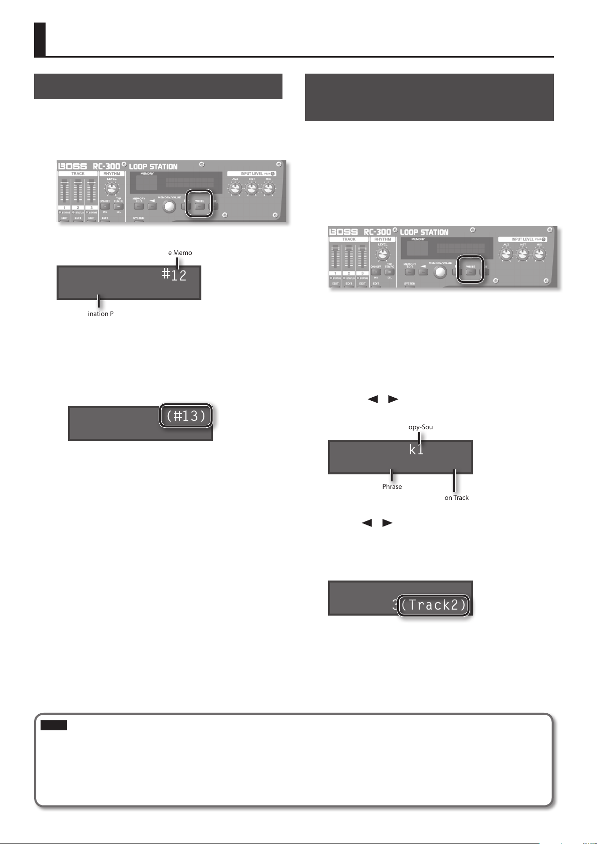
Saving a Phrase Memory (Write)
If you select a dierent phrase memory or turn o the power after
recording or overdubbing, the data you recorded will be lost. If you
want to keep the data, you must save it.
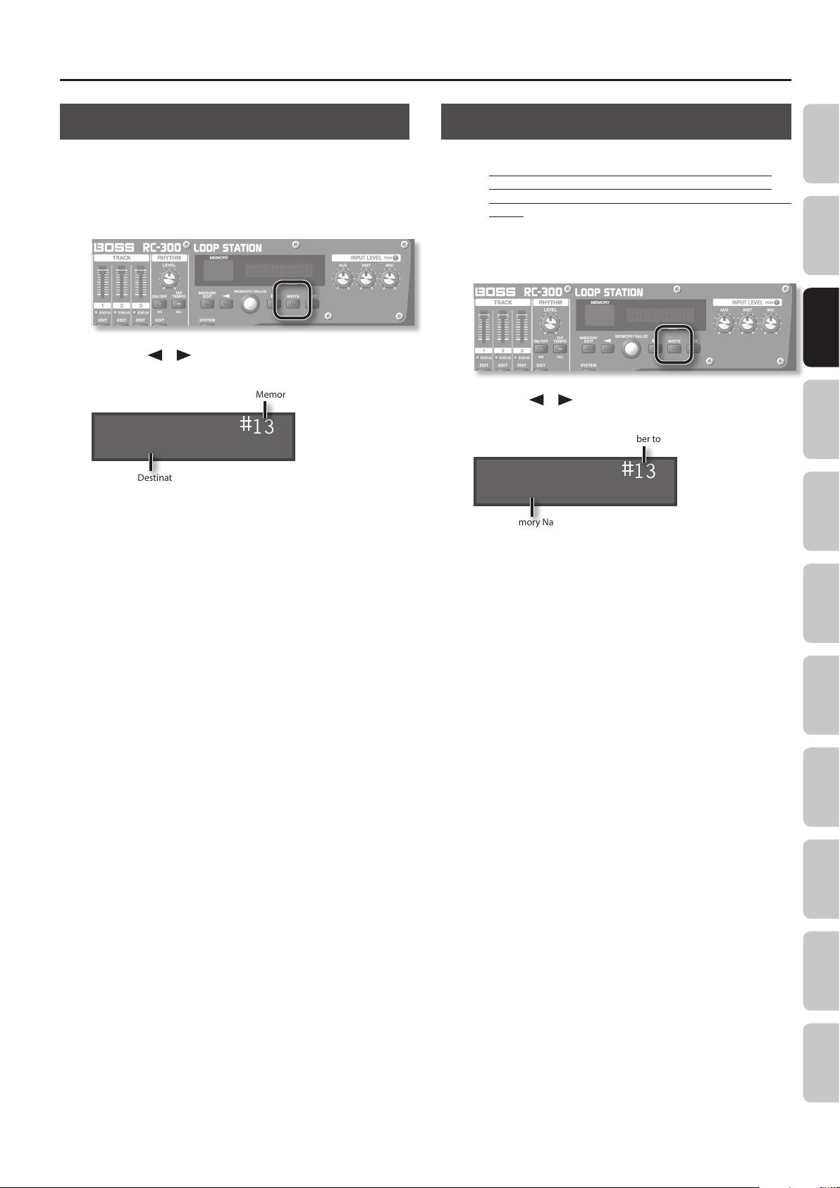
1. While playback is stopped, press the [WRITE] button.
The Write screen appears.
Save-Destination Phrase Memory Number
Write to 12
INIT MEMORY
Save-Destination Phrase Memory Name
2. Turn the [MEMORY/VALUE] knob to select the save-
destination phrase memory.
• This procedure is not required if the phrase memory number is
acceptable as is.
• Phrase memory numbers in which data has already been saved
are shown in parentheses, and cannot be overwritten.
Write to ( 13)
My Memory
Copying a Track from Another Phrase Memory (Track Copy)
You can then take a specic track from that phrase memory and
copy it to the current phrase memory.
This is a convenient method to use when you need a pattern with
the same backing, as it allows you to prepare tracks simply and
easily without having to start recording from scratch again.
1. To prevent loss of the content of the current work, press
the [WRITE] button twice to save the current phrase
memory.
Since you need to conrm the sound of the current source track,
you must select the copy-source phrase memory once in Track
Copy. Save the phrase memory so the content of the current
operation is not lost.
2. In the Play screen, select the phrase memory in which the
track you want to copy is recorded.
3. Press the [WRITE] button.
4. Press the [ ]/[ ] buttons until “Copy Track” appears in
the display.
Copy-Source Track
• The maximum recording time is a total of approximately 3 hours
for all phrase memories (including the track that has not been
saved). If the phrase memory cannot be saved because there is
insucient free memory, the display indicates “Memory Full!”
In this case, delete unneeded phrase memories (p. 15) and then
try the recording operation again.
3. Press the [WRITE] button; the phrase memory will be
saved.
• If you decide to cancel the save operation, press the [EXIT]
button.
• You can’t overwrite (i.e., save to) a phrase memory that already
contains data. If the display indicates “Not Empty!”, select an
empty phrase memory in which to save your data.
• You can assign a name to the phrase memory. For details, refer
to “Naming Phrase Memories (Memory Names)” (p. 20).
Copy Track1 to
Memory12 Track1
Copy-Destination Phrase memory
Copy-Destination Track
5. Use the [ ]/[ ] buttons to move the cursor, and turn
the [MEMORY/VALUE] knob to enter the copy-source
track, copy-destination phrase memory and track.
Track numbers in which data has already been saved are shown in
parentheses, and cannot be overwritten.
Copy Track1 to
Memory13(Track2)
6. Press the [WRITE] button; the track will be copied.
If you decide to cancel the operation, press the [EXIT] button.
When copying is nished, the Play screen returns to the display.
NOTE
* Please be aware that the contents of memory can be irretrievably lost as a result of a malfunction or improper operation of the unit. You
should back up important data as described in “Backing up to your computer” (p. 37).
* All due care is taken during repairs to avoid the loss of data. However, in certain cases, such as when there is damage to the memory, it may
not be possible to restore the data.
* Unfortunately, it may be impossible to restore the contents of data that was stored in the unit’s memory once it has been lost. Roland
Corporation assumes no liability concerning such loss of data.
14
Page 15
Saving a Phrase Memory
Exchanging Phrase Memories
You can exchange phrase memories with one another, rearranging
the phrase memories.
1. Select an exchange-source phrase memory.
2. Press the [WRITE] button.
3. Press the [ ]/[ ] buttons until “Exchange” appears in
the display.
Exchange-Destination Phrase Memory Number
Exchange 13
My Memory
Exchange-Destination Phrase Memory Name
4. Turn the [MEMORY/VALUE] knob to select the exchange-
destination phrase memory.
Deleting a Phrase Memory (Initialize)
This operation erases a phrase memory and initializes its settings.
* This device contains demo data (Phrase Memory 90–99).
Once you delete these, they cannot be recovered. Please
back them up as described in “Backing up to your computer”
(p. 37).
1. Select the phrase memory that you want to delete.
2. Press the [WRITE] button.
3. Press the [ ]/[ ] buttons until “Initialize” appears in the
display.
Phrase Memory Number to be Deleted
Initialize 13
My Memory
Phrase Memory Name to be Deleted
Overview Basic Operation Track
Phrase Memory
5. Press the [WRITE] button; the phrase memories will be
exchanged.
If you decide to cancel the operation, press the [EXIT] button.
4. Press the [WRITE] button; the phrase memory will be
deleted.
If you decide to cancel the operation, press the [EXIT] button.
Rhythm LOOP FX System Settings USB MIDI AppendixSaving
15
Page 16

Settings for Each Track
Overview of the Playback Settings
The RC-300 lets you specify the playback method independently for
each track.
Loop Playback Settings (Play Mode)
For each track, you can specify either loop playback or one-shot
(i.e., not looped).
If one-shot playback is selected, playback will stop when
it reaches the end of the phrase (it will not loop).
Track 1
Track 2
Track 3
Aligning the Beginning of Loop Playback (Loop Sync)
Play repeatedly, starting in synchronization with the beginning of the longest
phrase.
Loop
One Shot
Loop
Reference
Refer to the track setting “Play Mode” (p. 17).
If you turn Loop Sync on for two or more tracks, loop playback of
those tracks will be synchronized at the beginning of the longest
phrase with Tempo Sync on among these tracks.
For tracks whose Loop Sync is
o, playback will repeat at the
length of the phrase.
Synchronizing the Tempo (Tempo Sync)
Each track saves the tempo at which that track was recorded. This
is called the “original tempo” (p. 19) of the track. The phrase
memory also has a “phrase memory tempo” (p. 21) that is
shared by all tracks 1, 2, and 3.
Normally, you should leave Tempo Sync on, so all tracks will play
at the same tempo (the phrase memory tempo). If you turn Tempo
Sync o for tracks for which you don’t want the tempo to change
(such as those with special eects), you’ll be able to obtain playback
that is always at the original tempo.
Tracks for which Tempo Sync is on will
play at the phrase memory tempo.
Phrase Memory Tempo: 120
Track 1
Track 2
Track 3
Tempo Sync: ON
Original Tempo: 140
Tempo Sync: ON
Original Tempo: 100
Tempo Sync: OFF
Original Tempo: 80
Reference
Refer to the track setting “Tempo Sync” (p. 18).
Playback Tempo: 120
Playback Tempo: 120
Playback Tempo: 80
Tracks for which Tempo Sync is
o will play at the original tempo.
Specifying the Number of Measures in a Track (Measure)
Track 1
Track 2
Track 3
Loop Sync: ON
Loop Sync: ON
Loop Sync: OFF
Playback starting location
If you turn Loop Sync on, the beginning of the tracks will always
be aligned. This means that if tracks are already playing back, the
playback start location of the other tracks will become “the current
location of the phrase being played.” The following illustration is an
example of how playback will occur with three tracks that contain
the identical melody but have dierent loop sync settings.
For a track with Loop Sync on,
playback starts midway through the
phrase (from the current location).
Track 1
Track 2
Track 3
Loop Sync: ON
Loop Sync: ON
Loop Sync: OFF
Reference
Refer to the track setting “Loop Sync” (p. 18).
Automatically Adjusting the Phrase Length (Loop Quantize)
• If the rhythm is on
• If there is an already-recorded track whose Tempo Sync is turned on or Loop
Sync is turned on
• If the MIDI Sync is on
This function will automatically adjust the length of the phrase to match
the tempo and the time signature of the rhythm, even if the timing at which
recording ended was not quite accurate.
Start Stop
Recorded phrase
For a track with Loop Sync o,
playback always starts at the
beginning of the phrase.
Even if the timing is slightly
inaccurate, the phrase
length will automatically
be adjusted to the precise
measure interval.
You can specify the number of measures for each track. When
recording rhythm sounds or when recording along with other
tracks, it’s convenient to specify the number of measures before you
record, so that looping will occur at the specied measure length,
even if you don’t operate the pedal when you’ve nished recording.
Track 1
Track 2
Track 3
One measure
Four measures
Eight measures
Reference
Refer to the track setting “Measure” (p. 17).
Playing Only a Single Track (Single Track Play)
Normally, the RC-300 plays back its three tracks simultaneously.
However, if you turn on the phrase memory’s “Single Track Play”
setting, only one track will play.
If Single Track Play is on, the track that’s currently playing will stop when you
start playback of another track.
Track 1
Track 2
Track 3
Reference
Refer to the phrase memory setting “Single Tr Play” (p. 22).
16
Page 17

Settings for Each Track
Settings for Each Track
Here you can specify the playback method and other settings individually for each track.
First press the [EDIT] button of the track that you want to edit.
For details, refer to “Basic Editing Procedure” (p. 9).
Parameter Value Explanation
Track1:Play Mode
LOOP
Specifying How the Track Will Play (Play Mode)
This species whether the track playback will be looped or one-shot (i.e., not looped).
Loop
Track 1
One Shot
Track 2
Loop
Track 3
* Recording/overdubbing cannot be carried out with respect to tracks that are set to “ONE SHOT.” To create a track
intended for one-shot playback, you rst need to carry out recording/overdubbing while it is set to “LOOP.” Then, you
should change its setting to “ONE SHOT.”
* If you do not want to synchronize tracks that are set to “ONE SHOT” with the other tracks, set Tempo Sync (p. 18) to OFF.
LOOP Conventional loop playback.
The phrase will play only once from the beginning to the end of the track, and then stop
ONE SHOT
automatically.
If you press the [REC/DUB/PLAY] pedal during playback, playback will begin again from the
beginning of the track (Retrigger Playback).
Overview Basic Operation Saving
If one-shot playback is
selected, playback will
stop when it reaches the
end of the phrase (it will
not loop).
Phrase Memory
Track1:Reverse
OFF
Track1:Measure
(BPM120.0) AUTO
Original Tempo (p. 19)
Track1:Stop Mode
IMMEDIATE
Playing a Track Backward (Reverse)
This species whether the track will play forward in the conventional manner, or play backward in time (reverse playback).
OFF Playback is normal.
ON Playback is reversed.
Specifying the Number of Measures in a Track (Measure)
You can specify the number of measures for each track. When recording rhythm sounds or when recording along
with other tracks, it’s convenient to specify the number of measures before you record, so that looping will occur at
the specied measure length, even if you don’t operate the pedal when you’ve nished recording.
Track 1
Track 2
Track 3
AUTO
FREE
1, 2, 3... The number of measures will be set manually.
One measure
Four measures
Eight measures
Tracks that are set to AUTO will have the same number of measures. The number of
measures is determined by the rst-recorded track of the tracks that are set to AUTO. For
example, if all tracks are set to AUTO, the value set as the number of measures for the
second and subsequent tracks will be identical to the number of measures in the rst track
that was recorded.
The number of measures will be set automatically, corresponding to the length of the recording.
Specifying How the Track Will Stop (Stop Mode)
This species how the track will stop when you press the [STOP] pedal.
• The PLAY indicator will blink until playback stops.
• If you press the [STOP] pedal once again before playback stops, playback will stop immediately.
* You can’t overdub during the time until playback stops.
IMMEDIATE Playback will stop immediately.
FADE OUT Playback will fade out and then stop.
LOOP END Playback will continue to the end of the loop, and then stop.
Rhythm LOOP FX System Settings USB MIDI AppendixTrack
Track1:PlayLevel
100
Adjusting the playback level of the Tracks (Play Level)
You can adjust the playback level of the tracks. You can also change this value
with the TRACK [1]–[3] sliders.
0–200 Playback level of the track.
17
Page 18

Settings for Each Track
Parameter Value Explanation
Track1:Rec Level
100
Track1:Pan
CENTER
Track1:Loop Sync
ON
Adjusting the recording level of the Tracks (Recording Level)
You can adjust the recording level of the tracks.
If you set the recording level at 100 (default value), the volume of the performance and that
0–200
of the recording will be identical.
If you set the recording level to a value lower than 100, the volume of the recording will be
lower than that of the performance. As a result, the sound of the performance won’t get
buried by the recorded sound, even if you record a multiple number of times.
Adjusting the Positioning of the Track’s Sound (Pan)
You can adjust the positioning (panning) of the track’s sound.
L50–CENTER–R50
With the “CENTER” setting, the sound will be heard from the center.
“L” settings position the sound toward the left, and “R” settings position the sound toward
the right. With a setting of L50, the sound will be heard only from the left.
Aligning the Beginning of Loop Playback (Loop Sync)
If you turn Loop Sync on for two or more tracks, loop playback of those tracks will be synchronized at the beginning
of the longest phrase with Tempo Sync on among these tracks.
Play repeatedly, starting in synchronization with the
beginning of the longest phrase.
Track 1
Track 2
Track 3
Loop Sync: ON
Loop Sync: ON
Loop Sync: OFF
For tracks whose Loop Sync is o, playback
will repeat at the length of the phrase.
Track1:TempoSync
ON
Playback starting location
If you turn Loop Sync on, the beginning of the tracks will always be aligned. This means that if tracks are already
playing back, the playback start location of the other tracks will become “the current location of the phrase being
played.” The following illustration is an example of how playback will occur with three tracks that contain the
identical melody but have dierent loop sync settings.
For a track with Loop Sync on, playback starts midway
through the phrase (from the current location).
Track 1
Track 2
Track 3
OFF Playback will loop at the length of the phrase.
ON
Loop Sync: ON
Loop Sync: ON
Loop Sync: OFF
Playback will loop in synchronization with the start of the longest phrase of the tracks for
which Loop Sync is turned on.
For a track with Loop Sync o, playback
always starts at the beginning of the phrase.
Synchronizing the Tempo (Tempo Sync)
Each track saves the tempo at which that track was recorded. This is called the “original tempo” of the track. The
phrase memory also has a “phrase memory tempo” that is shared by all tracks 1, 2, and 3.
Normally, you should leave Tempo Sync on, so all tracks will play at the same tempo (the phrase memory tempo).
If you turn Tempo Sync o for tracks for which you don’t want the tempo to change (such as those with special
eects), you’ll be able to obtain playback that is always at the original tempo (track 3 in the illustration below).
Phrase Memory Tempo: 120
Track 1
Track 2
Track 3
Tempo Sync: ON
Original Tempo: 140
Tempo Sync: ON
Original Tempo: 100
Tempo Sync: OFF
Original Tempo: 80
Tracks for which Tempo Sync is on will play at the phrase memory tempo.
Playback Tempo: 120
Playback Tempo: 120
Playback Tempo: 80
Tracks for which Tempo
Sync is o will play at the
original tempo.
18
OFF The track will play at its own original tempo.
ON The track will play at the phrase memory tempo.
Page 19

Settings for Each Track
Parameter Value Explanation
Track1:Output
MAIN+SUB
Assigning a Track’s Output Jacks (Output Select)
For each track, you can specify the jacks from which its sound will be output.
If desired, you can also make this setting apply to all phrase memories. g “Using the
Same Output Jacks for All Phrase Memories (Input/Track 1, 2, 3/Rhythm Output)” (p.
33)
MAIN The sound is output from the MAIN OUTPUT and PHONES jacks.
SUB
MAIN+SUB
The sound is output from the SUB OUTPUT jacks. The sound is not output from the MAIN
OUTPUT and PHONES jacks.
The sound is output from the MAIN and SUB OUTPUT jacks and the PHONES jack.
Overview Basic Operation Saving
Phrase Memory
About original tempo
Each track saves the tempo at which that track was recorded. This is called the “original tempo” of the track. The phrase memory also has a
“phrase memory tempo” (p. 21) that is shared by all tracks 1, 2, and 3.
When recording ends, the original tempo is automatically calculated according to the following conditions.
Condition Original tempo value to be saved
Rhythm is playing
Other tracks have phrases with the following settings
• Play Mode at LOOP, Loop Sync ON
• Play Mode at LOOP, Tempo Sync ON
Cases other than the above
The track’s number of measures (Measure:
p. 17) has been specied
Original tempo will be set from the “phrase memory tempo” (p. 21).
The original tempo is automatically calculated according to the following conditions.
Phrase Memory Tempo will be set to the same value as the automatically calculated original tempo.
The original tempo is calculated according to the rhythm’s time signature (Beat: p. 25) and the number of
measures (Measure).
For example, if the time signature (Beat) is “4/4,” the number of measures (Measure)
is “4,” and you’ve recorded for six seconds, the calculated tempo will be “160.”
4/4 time signature
If the number of measures (Measure) is set to “2,” the calculated tempo will be “80.”
4/4 time signature
The recorded number of measures is assumed to be “1, 2, 4, 8, 16... measures,” and the original tempo
will be calculated in the range of “80–160.”
4 measures
2 measures
Rhythm LOOP FX System Settings USB MIDI AppendixTrack
The track’s number of measures (Measure:
p. 17) is not specied (AUTO/FREE)
For example, if “4/4” is specied as the time signature (Beat), and you record for eight seconds,
the calculated tempo will be “120” (a tempo in the range of “80–160” will be selected).
In the case of 1 measure… Tempo: 30
In the case of 2 measures… Tempo: 60
In the case of 3 measures… Tempo: 120
In the case of 4 measures… Tempo: 240
19
Page 20

Phrase Memory Settings
Here you can make settings that apply to the entire phrase memory.
First press the [MEMORY EDIT] button.
For details, refer to “Basic Editing Procedure” (p. 9).
Parameter Value Explanation
Memory:Name
INIT MEMORY
Memory:Level
100
Memory:Input Out
MAIN+SUB
Naming Phrase Memories (Memory Names)
You can give names to phrase memories (memory names) using up to 16 characters.
To access the memory name screen, press the [MEMORY EDIT] button and then press the [
MEMO
Normally, the [ ]/[ ] buttons are used to select parameters, but in the memory name screen they are used
to move the cursor. When the cursor is located at the far right, pressing the [
you to the next parameter.
Use the [
VALUE] knob to edit the character. You can also use the following buttons.
Button Function
CAPS (RHYTHM EDIT)
INS (RHYTHM ON/OFF) Inserts a blank space at the cursor position.
DEL (RHYTHM TAP TEMPO)
]/[ ] buttons to move the cursor to the character that you want to edit, and turn the [MEMORY/
Alternately switches the letter at the cursor position between uppercase and
lowercase.
Deletes the character at the cursor position and shifts all characters after it to the
left.
] button.
] button once again will take
Adjusting the Phrase Memory Volume (Memory Level)
You can adjust the phrase memory volume.
This is convenient when you want to adjust the output volume for both the MAIN OUTPUT and SUB OUTPUT jacks
simultaneously.
Normally, this is set to the center with a level of 100.
0–200 Volume of the phrase memory
Setting the Output Jacks for the Sounds Being Input (Input Output Select)
This selects the output jacks to be used for the output of sounds arriving at the INPUT jacks (AUX, INST, MIC).
20
If desired, you can also make this setting apply to all phrase memories. g “Using the Same Output Jacks for All
Phrase Memories (Input/Track 1, 2, 3/Rhythm Output)” (p. 33)
MAIN The sound is output from the MAIN OUTPUT and PHONES jacks.
SUB
MAIN+SUB
MUTE
The sound is output from the SUB OUTPUT jacks. The sound is not output from the MAIN
OUTPUT and PHONES jacks.
The sound is output from the MAIN and SUB OUTPUT jacks and the PHONES jack.
The input sound will not be output.
* Tracks will be recorded.
Page 21

Phrase Memory Settings
Parameter Value Explanation
Memory:MIDI Sync
INTERNAL
Memory:Overdub
Mode OVERDUB
Synchronizing the Tempo of Two RC-300 Units (MIDI Sync)
Two RC-300 units can be synchronized after connecting them together using a MIDI cable. For details, refer to “Connecting Two RC-300 Units” (p. 39). The “MIDI Sync” setting allows two RC-300 units to play back in synchronization
at the same tempo.
MIDI OUT connector MIDI IN connector
RC-300 (Master unit) RC-300 (Slave unit)
Reference
For more detailed information about MIDI and synchronization, refer to “MIDI settings” (p. 38).
INTERNAL
MIDI
This RC-300 unit will operate at its own specied phrase memory tempo. Choose the
“INTERNAL” setting if you’re using the RC-300 by itself, or if this is the master RC-300 unit.
This RC-300 unit will synchronize to MIDI data received from the master RC-300 unit.
Choose the “MIDI” setting for the slave RC-300 unit.
Setting the Overdubbing Method (Overdubbing Mode)
You can set the overdubbing method.
OVERDUB
REPLACE
The new performance is layered onto the prerecorded tracks. If overdubbing is repeated,
the next performance is layered on top of the previous material, allowing you to create an
ensemble in a single track.
Tracks with existing recordings are overwritten as new tracks are recorded over them.
Overwriting takes places while the previously recorded tracks are played back, allowing you
to achieve a kind of delay eect similar to that obtained from an eects processor.
Overview Basic Operation Saving Track Rhythm LOOP FX System Settings USB MIDI Appendix
Phrase Memory
Memory:Rec Mode
STEREO
Memory:Tempo
120.0
Switching Between Stereo and Mono (Recording Mode)
Before you record, you must specify whether you’re recording in stereo or in mono.
• The recordable time is not aected by the stereo/mono setting (choosing mono will not increase the recordable time).
• You can’t change the stereo/mono setting of a phrase memory once you’ve recorded it.
STEREO Recording will take place in stereo.
MONO Recording will take place in mono.
Specifying a Phrase Memory’s Tempo
Each phrase memory has a “phrase memory tempo,” which applies to the entire phrase memory.
The phrase memory tempo is also the tempo of the rhythm (p. 25).
Setting the tempo
Press the [ ] /[ ] buttons to move the cursor to the digit you want to change, then turn
the [MEMORY/VALUE] knob to adjust the phrase memory tempo.
MEMO
Normally, the [ ]/[ ] buttons are used to select parameters, but in the tempo
screen they are used to move the cursor. When the cursor is located at the far right,
40.0–250.0
pressing the [
Using the [TAP TEMPO] button to set the tempo
Press the [TAP TEMPO] button several times in rhythm with the desired tempo.
The tempo will be set so it matches the timing you’ve used when pressing the button.
Using the [STOP] pedal to set the tempo
You can also set the tempo by pressing the [STOP] pedal several times in succession.
] button once again will take you to the next parameter.
Memory:Fade Out
Time 50
Adjusting the Time Used to Fade Out (Fade-Out Time)
This species the fade-out time used when a track’s stop mode (p. 17) is set to “FADE OUT.”
0–100 This is the fade-out time. At a setting of “100,” the fade-out time will be 20 seconds.
21
Page 22

Phrase Memory Settings
Parameter Value Explanation
Memory:Auto Rec
OFF
Memory:Single Tr
Play OFF
Simultaneously Starting Recording When Sounds are Input (Auto Recording)
“Auto recording” starts recording the moment you begin playing your guitar or play back your audio player.
OFF Recording will begin the instant you press the [REC/DUB/PLAY] pedal.
ON
When you press the [REC/DUB/PLAY] pedal, the REC indicator will blink rapidly, and the
RC-300 will enter recording-standby mode. When you begin playing, the REC indicator will
light and recording will start.
Playing Only a Single Track (Single Track Play)
Normally, the RC-300 plays back its three tracks simultaneously. However, if you turn on the phrase memory’s “Single
Track Play” setting, only one track will play.
If Single Track Play is on, the track that’s currently playing will stop when you
start playback of another track.
Track 1
Track 2
Track 3
* If Track Change (p. 22) is set to “LOOP END,” the track will change at the end of the loop.
* To ensure that playback always takes place from the beginning of the phrase, you need to set Loop Sync (p. 22) to
“OFF.”
OFF
Play back all tracks
Memory:Track
Change IMMEDIATE
Memory:Reverb
Level 0
ON Play back only a single track
Specifying how the Track will Switch (Track Change Mode)
You can specify how the tracks will be switched when using Single Track Play.
IMMEDIATE The change will occur immediately.
LOOP END The change will occur after playback has reached the end of the loop.
Adjusting the Reverb Depth (Reverb Level)
This adjusts the depth of the reverb. The reverb is applied to sounds for which the MAIN OUTPUT jacks have been assigned
as the output destination.
0–100 Reverb depth
22
Page 23

Phrase Memory Settings
Assigning the Function of Pedals and External Controllers (Assign)
For each phrase memory, you can assign the function of the RC-300’s pedals and any connected external pedals (EXP
pedals, foot switches: p. 24). You can also make assignments for control change messages received from an external MIDI
device (e.g., FC-300).
For each phrase memory, you can create eight dierent assignments (assignment numbers 1–8), which specify the
parameter controlled by each controller.
Parameter Value Explanation
Assign1 Switch
ON
Assign1 Target
EFFECT CONTROL
Enabling Assignments 1–8 (Assign Switch)
Here you can specify whether assignments will be used.
OFF The assignment will not be used.
ON The assignment will be used.
Specifying the Assignment Target (Assign Target)
Here you can choose the Assignment Target. In addition to the following assignment targets, you can also specify
a track, rhythm, or a LOOP FX parameter as the assignment target. For details on the parameters, refer to the
explanation of each parameter in this manual.
* Some parameters cannot be controlled during performance.
MEM Tempo(TAP)
EFFECT CONTROL Applies an eect suitable for the selected LOOP FX type.
MEMORY INC
MEMORY DEC
LOOP FX ON/OFF Switches the LOOP FX on/o.
FX TYPE INC
FX TYPE DEC
UNDO/REDO Allows you to undo/redo the last recording or overdubbing of a track (p. 12).
TR1–3 UNDO/REDO Allows you to undo/redo a specic track (p. 12).
TR1–3 PLAY/STOP Allows you to play/stop a specic track.
ALL PLAY/STOP Allows you to simultaneously play/stop all tracks.
TRACK1–3 CLEAR Clears the track (p. 12).
INPUT MASTER LEV Adjusts the input level from the INPUT (AUX, INST, MIC) jacks.
INPUT MIC SWITCH Switches the INPUT MIC jack input on/o.
By pressing the pedal several times in succession, the phrase memory tempo can be set so
it matches the timing you’ve used when pressing the pedal.
Switches the phrase memory.
Switches the LOOP FX type.
Overview Basic Operation Saving Track Rhythm LOOP FX System Settings USB MIDI Appendix
Phrase Memory
Assign1TargetMin
Assign1TargetMax
100
Assign1 Source
EXP1 PEDAL
CC#1–#31, CC#64–#95 Transmits the control change message specied here from the MIDI OUT connector.
Specifying the Target Range (Target Range)
0
Here you can specify the range in which the parameter can be controlled. The value will depend on the parameter
that’s assigned as the Target (Assign Target).
Specifying the Controller (Assign Source)
Here you can specify the controller (source) that will control the target.
EXP1 PEDAL The RC-300’s [EXP 1] pedal
The RC-300’s [LOOP FX] pedal
LOOP FX PEDAL
CTL1–4 PEDAL A foot switch 1–4 connected to the CTL/EXP jacks (p. 24)
EXP2–3 PEDAL An EXP pedal 2–3 connected to the CTL/EXP jacks (p. 24)
TRACK1–3 REC/DUB The beginning of recording/overdubbing triggered by the track 1–3 [REC/DUB/PLAY ] pedal
TRACK1–3 PLAY The beginning of playback triggered by the track 1–3 [REC/DUB/PLAY] pedal
SYNC START/STOP ALL START/STOP messages from the master RC-300 unit (p. 39).
CC#1–#31, CC#64–#95 Control change messages (1–31, 64–95) from an external MIDI device
* The [LOOP FX] pedal switches the LOOP FX on/o. If you don’t want to use the [LOOP
FX] pedal to switch the LOOP FX on/o, choose “ASSIGN” as the setting of “Specifying the
Operation of the [LOOP FX] Pedal” (p. 32).
23
Page 24

Phrase Memory Settings
Parameter Value Explanation
Assign1 Src Mode
MOMENT
Specifying the Type of Operation (Source Mode)
If a momentary-type foot switch (such as the separately sold FS-5U) is connected as the source, you can specify how
foot switch operations will aect the value.
* If the [LOOP FX] pedal is set to MOMENT, it will no longer be possible to enter Pedal Function mode (p. 10) by
holding down the [LOOP FX] pedal for two seconds or longer.
MOMENT
TOGGLE
The setting will normally be o (minimum value); it will be on (maximum value) only while
you continue holding down the foot switch.
The setting will alternate between o (minimum value) and on (maximum value) each time
you press the foot switch.
Connecting to External Pedals
Connect your EXP pedals (EV-5, etc. ; available separately) or foot switches (FS-5U, FS-6; available separately) as shown in the illustration.
The function of the external pedal (EXP pedal or foot switch) can be assigned independently for each phrase memory. For details, refer to “Assigning
the Function of Pedals and External Controllers (Assign)” (p. 23).
When Connecting EV-5s When Connecting FS-5Us When Connecting FS-6s
Cable:
Stereo 1/4” phone type
fg
1/4” phone type x 2
Cable:
Stereo 1/4” phone type
fg
Stereo 1/4” phone type
Red
CTL 4 CTL 4 CTL 2EXP 3 CTL 2CTL 3 CTL 3 CTL 1EXP 2 CTL 1
* Use only the specied expression pedal (Roland
EV-5, etc. ; sold separately). By connecting
any other expression pedals, you risk causing
malfunction and/or damage to the unit.
* If you use a mono cable to connect a single FS-5U, the CTL 1, 2 jack will be CTL 1, and the CTL 3, 4 jack will be CTL 3.
Default assignments of functions controlled
The default assignments are as follows. If you simply connect pedals without making any settings, you can use them to control the following
parameters and functions.
Assign Switch Assign Source Assign Target Explanation
Assign1 ON EXP1 PEDAL
Assign2 ON EXP2 PEDAL
RedWhite White
POLARITY switch
EFFECT CONTROL
Level The pedal will control the volume of the phrase memory.
The eect that’s most suitable for the selected LOOP FX type will be
applied.
MODE/POLARITY switch
24
Assign3 ON C TL1 PEDAL
Assign4 ON C TL2 PEDAL MEMORY DEC
Assign5 ON C TL3 PEDAL FX TYPE INC
Assign6 ON C TL4 PEDAL FX TYPE DEC
Assign7 ON SYNC START/STOP ALL PLAY/STOP
Assign8 OFF
MEMORY INC
The pedals will switch phrase memories.
The pedals will switch the LOOP FX type.
All tracks can be simultaneously played/stopped upon reception of
ALL START/STOP messages from the master RC-300 unit (p. 39).
Page 25

About Rhythm
In addition to its three tracks, the RC-300 can also play a “rhythm.”
You can record while listening to a rhythm at the tempo you specify.
Sounding a Rhythm
1. Press the RHYTHM [ON/OFF] button to turn the rhythm sound on/o.
• Use the RHYTHM [LEVEL] knob to adjust the volume of the rhythm.
• The [TAP TEMPO] button will blink in time with the rhythm (red on the rst beat, green on subsequent beats).
• When you save a phrase memory (p. 14), the rhythm setting selected at that time will also be saved.
Setting the tempo
The RC-300’s tempo settings include a “phrase memory tempo” (p. 21) that’s shared by tracks 1, 2, and 3, and an “original tempo” (p. 19)
for each track. The rhythm will sound at the “phrase memory tempo.”
1. Press the [TAP TEMPO] button.
The phrase memory tempo is displayed.
Memory:Tempo
120.0
Overview Basic Operation Saving Track
Phrase Memory
Set the tempo as described in “Specifying a Phrase Memory’s Tempo” (p. 21).
* You can also set the tempo by pressing the [STOP] pedal or the [TAP TEMPO] button several times.
Rhythm Settings
Here’s how to make rhythm settings.
First press the RHYTHM [EDIT] button.
For details, refer to “Basic Editing Procedure” (p. 9).
Parameter Value Explanation
Rhythm:Pattern
Simple Beat 1
Rhythm:Beat
4/4
Selecting the Rhythm Sound (Rhythm Pattern)
You can select the rhythm pattern from a choice of rock drums, Latin percussion, and other patterns.
Reference
Refer to “Rhythm pattern list” (p. 27).
Selecting the Beat (Time Signature) for the Rhythm Sound (Beat)
This selects the rhythm sound beat.
* You cannot change the beat after the track is recorded. Be sure to set this before recording.
2/4, 3/4, 4/4,
5/4, 6/4, 7/4, 5/8, 6/8,
7/8, 8/8, 9/8, 10/8,
11/8, 12/8, 13/8, 14/8,
15/8
LOOP FX System Settings USB MIDI AppendixRhythm
Time signature of the rhythm sound
25
Page 26

About Rhythm
Parameter Value Explanation
Rhythm:Rec Count
OFF
Rhythm:PlayCount
OFF
Rhythm:Stop
OFF
Rhythm:Level
100
Playing a Count-In When Recording (Recording Count-In)
You can have recording start after a count-in sound is played.
A count-in won’t be sounded when a track for which Loop Sync is ON is being played back.
OFF No count-in is played.
1MEAS Recording starts after a one-measure count-in is played.
Playing a Count-In for Playback (Playback Count-In)
You can have playback start after a count-in sound is played.
OFF No count-in is played.
1MEAS Playback starts after a one-measure count-in is played.
Stopping the Rhythm When the First Recording Ends (Rhythm Stop)
You can make the rhythm sound stop when the rst pass of recording ends. The rhythm sound will stop when you
press the [REC/DUB/PLAY] pedal to begin looping (i.e., when the RC-300 switches to overdubbing or playback).
OFF The rhythm will not stop when the rst pass of recording ends.
REC END The rhythm will stop when the rst pass of recording ends.
Adjusting the Volume of the Rhythm Sound (Rhythm Level)
This adjusts the volume of the rhythm sound. You can also change this value with the RHYTHM[LEVEL] knob.
Rhythm:Output
MAIN+SUB
0–200 Volume of the rhythm sound
Setting the Output Jacks for the Rhythm Sound (Rhythm Output Select)
You can select the output jacks to which the rhythm sound is output.
If desired, you can also make this setting apply to all phrase memories. g “Using the Same Output Jacks for All
Phrase Memories (Input/Track 1, 2, 3/Rhythm Output)” (p. 33)
MAIN The sound is output from the MAIN OUTPUT and PHONES jacks.
SUB
MAIN+SUB The sound is output from the MAIN and SUB OUTPUT jacks and the PHONES jack.
The sound is output from the SUB OUTPUT jacks. The sound is not output from the MAIN
OUTPUT and PHONES jacks.
26
Page 27

About Rhythm
Rhythm pattern list
g.03-100-Guide
Beat Pattern
Simple Beat 1–4
Shue 1–2
Hi-Hat 1–2
2/4
Kick & Hi-Hat 1–5
Rim & Hi-Hat 1–4
Conga & Hi-Hat 1–3
Simple Beat 1–8
Groove Beat 1–2
Shue
3/4
Hi-Hat
Kick & Hi-Hat 1–3
Rim & Hi-Hat 1–4
Conga & Hi-Hat 1–2
Simple Beat 1–5
Downbeat Snare
Rock 1–5
Latin Rock 1–2
Groove Beat 1–5
Shue 1–6
1/2 Shue 1–2
16th Shue 1–2
Shue Reggae
Pop 1–3
Funk 1–3
4/4
Fusion 1–3
Swing
Bossa 1–3
Samba 1–3
Clave 1–2
909 Beat
909 Clap
R&B 1–2
Hi-Hat
Kick & Hi-Hat 1–2
Conga & Hi-Hat
Conga & Maracas
Simple Beat 1–4
Groove Beat 1–3
Swing 1–2
5/4
Hi-Hat 1–4
Kick & Hi-Hat 1–4
Rim & Hi-Hat
Conga & Hi-Hat 1–2
Beat Pattern
Simple Beat 1–7
Groove Beat 1–2
Shue
Swing 1–2
Bossa Feel
6/4
Samba Feel 1–2
909 Beat
909 Clap
Hi-Hat 1–2
Kick & Hi-Hat
Conga & Maracas
Simple Beat 1–7
Groove Beat 1–2
Shue
Swing 1–2
Bossa Feel
7/4
Samba Feel 1–2
909 Beat
909 Clap
Hi-Hat 1–2
Kick & Hi-Hat
Conga & Maracas
Simple Beat 1–10
Bossa Feel
Samba Feel 1–2
909 Beat
5/8
909 Clap
Hi-Hat 1–3
Kick & Hi-Hat
Rim & Hi-Hat
Conga & Maracas
Simple Beat 1–10
Swing 1–2
Bossa Feel
Samba Feel 1–2
6/8
909 Beat
909 Clap
Hi-Hat 1–2
Kick & Hi-Hat
Conga & Maracas
Simple Beat 1–9
Bossa Feel
Samba Feel 1–2
909 Beat
909 Clap
7/8
Hi-Hat 1–2
Kick & Hi-Hat 1–2
Rim & Hi-Hat
Conga & Maracas
Beat Pattern
Simple Beat 1–6
Groove Beat 1–3
Bossa Feel
Samba Feel 1–2
909 Beat
8/8
909 Clap
Hi-Hat 1–2
Kick & Hi-Hat 1–2
Rim & Hi-Hat
Conga & Maracas
Simple Beat 1–6
Groove Beat 1–3
Bossa Feel
Samba Feel 1–2
909 Beat
9/8
909 Clap
Hi-Hat 1–2
Kick & Hi-Hat 1–2
Rim & Hi-Hat
Conga & Maracas
Simple Beat 1–6
Groove Beat 1–3
Bossa Feel
Samba Feel 1–2
909 Beat
10/8
909 Clap
Hi-Hat 1–2
Kick & Hi-Hat 1–2
Rim & Hi-Hat
Conga & Maracas
Simple Beat 1–6
Groove Beat 1–3
Bossa Feel
Samba Feel 1–2
909 Beat
11/8
909 Clap
Hi-Hat 1–2
Kick & Hi-Hat 1–2
Rim & Hi-Hat
Conga & Maracas
Simple Beat 1–6
Groove Beat 1–3
Bossa Feel
Samba Feel 1–2
909 Beat
12/8
909 Clap
Hi-Hat 1–2
Kick & Hi-Hat 1–2
Rim & Hi-Hat
Conga & Maracas
Beat Pattern
Simple Beat 1–6
Groove Beat 1–3
Bossa Feel
Samba Feel 1–2
13/8
Hi-Hat 1–2
Kick & Hi-Hat 1–2
Rim & Hi-Hat
Conga & Maracas
Simple Beat 1–6
Groove Beat 1–3
Bossa Feel
Samba Feel 1–2
909 Beat
14/8
909 Clap
Hi-Hat 1–2
Kick & Hi-Hat 1–2
Rim & Hi-Hat
Conga & Maracas
Simple Beat 1–6
Groove Beat 1–3
Bossa Feel
Samba Feel 1–2
909 Beat
15/8
909 Clap
Hi-Hat 1–2
Kick & Hi-Hat 1–2
Rim & Hi-Hat
Conga & Maracas
Overview Basic Operation Saving Track
Phrase Memory
LOOP FX System Settings USB MIDI AppendixRhythm
27
Page 28

Using LOOP FX
You can apply an eect to the sound of each track.
This eect is called a “LOOP FX.”
The eect will be applied in synchronization with the phrase memory tempo.
Turning LOOP FX On/O
1. Press the [LOOP FX] pedal to turn LOOP FX on/o.
Controlling LOOP FX
You can control the LOOP FX by the depth to which you depress the
[EXP 1] pedal.
An eect that is most appropriate for the selected LOOP FX type will be applied by the [EXP 1] pedal.
Reference
You can also assign the [EXP 1] pedal to control something other than LOOP FX.
For details, refer to “Assigning the Function of Pedals and External Controllers (Assign)” (p. 23).
LOOP FX Settings
First press the [LOOP FX] button.
For details, refer to “Basic Editing Procedure” (p. 9).
* The LOOP FX parameters will dier depending on the LOOP FX that is selected.
Parameter Value Explanation
FX:Target
MAIN OUT TOTAL
Specifying What LOOP FX Will Apply To (LOOP FX Target)
Here you can specify the sound to which the LOOP FX will be applied.
INPUT
TRACK1 Track 1
TRACK2 Track 2
TRACK3 Track 3
MAIN OUT TRACKS
MAIN OUT TR+RHY
MAIN OUT TOTAL
Input sound from the INPUT jacks
* The sound with the LOOP FX applied will be recorded.
Track 1 + Track 2 + Track 3
* LOOP FX cannot be applied to the sound output from the SUB OUTPUT jacks.
Track 1 + Track 2 + Track 3 + Rhythm
* LOOP FX cannot be applied to the sound output from the SUB OUTPUT jacks.
Track 1 + Track 2 + Track 3 + Rhythm + Input sound from the INPUT jacks
* LOOP FX cannot be applied to the sound output from the SUB OUTPUT jacks.
28
Page 29

Using LOOP FX
Parameter Value Explanation
FX:Category
TRANSPOSE
FX:Type
TRANSPOSE
Selecting the LOOP FX Category and Type (LOOP FX Category, LOOP FX Type)
Here you can select the LOOP FX category and type.
Press the [
category. (You can’t select types across categories.)
] button to access the type screen, and then select the LOOP FX type from within the selected
Using pedals to select a LOOP FX (Pedal Function mode)
Hold down the [LOOP FX] pedal for two seconds or longer to put the RC-300 in Pedal
Function mode; now you can use the TRACK 3 pedals to select the LOOP FX type.
1
Hold for 2 seconds or longer
Blink
2
Select a LOOP FX
3
Press once again to return to normal mode
Overview Basic Operation Saving Track
Phrase Memory
Category Type Explanation
TRANSPOSE TRANSPOSE Transposes the sound when you turn the eect on.
FLANGER
PHASER Gives the sound a swishing quality by adding a phase-shifted sound.
PAN Moves the stereo position (pan).
MODULATION
VOICE
GUITAR GT->BASS Transforms a guitar sound into a bass sound.
OTHER
TREMOLO Cyclically modulates the volume.
SLICER
BEND
CHORUS
ROBOT Adds robot-like qualities to the voice.
FEMALE Makes the voice more feminine.
MALE Makes the voice more masculine.
FILTER A lter with an extremely steep slope (a steep cuto ).
DELAY
LO-FI
DISTORTION Distorts the sound to produce long sustain.
Produces a metallic resonance reminiscent of a jet airplane taking o and
landing
Repeatedly cuts the sound, transforming a conventional sound to create
the impression of a rhythmic backing.
Produces pitch-up/pitch-down eects that can’t be created using a
guitar’s tremolo arm.
Adds a slightly modulated sound to the direct sound, creating beautiful
spaciousness and depth.
Adds a delayed sound to the direct sound, giving the sound greater
depth or creating special eects.
This eect intentionally degrades the sound to create a distinctive
character.
Rhythm System Settings USB MIDI AppendixLOOP FX
29
Page 30

Using LOOP FX
TRANSPOSE setting
Parameter Value Explanation
FX:Transpose
+1
-12–+12
Specify the amount of transposition in semitone units that will
occur when the eect is on.
With a setting of +12, the pitch
will be one octave higher when
the eect is on.
FLANGER, PHASER settings
Parameter Value Explanation
FX:Rate
FX:Depth
FX:Manual
FX:Resonance
FX:Gate Rate
FX:Step Rate
0–100,
25
4 MEAS–
0–100 Adjusts the richness of the eect.
50
0–100
75
0–100 Adjusts the intensity of the eect.
80
OFF, 1–100,
OFF
4 MEAS–
OFF, 1–100,
OFF
4 MEAS–
Adjusts the speed of the eect.
Adjusts the band to which eect
is applied.
* FLANGER only
Species the operating speed of
the gate.
* PHASER only
Adjusts the rate of the stepwise
change in the phaser eect.
SLICER settings
Parameter Value Explanation
FX:Mode
FX:Rate
FX:Dir.Mix
P01
50
50
P01–P10
0–100,
1 MEAS–
0–100
Selects the slice pattern used to
cut the sound.
Species the rate at which the
16-step sequence will repeat.
Controls the volume of the direct
sound when the eect is on.
BEND settings
Parameter Value Explanation
FX:Pitch
+1 OCT
FX:Rise Time
FX:Fall Time
-3 OCT–+4 OCT,
-2 OCT & VIBRATO,
+2 OCT & VIBRATO,
-2 OCT & +2 OCT
50
0–100
50
0–100
Species the amount of
pitch shift.
Species the time over
which the specied pitch
is reached (the RISE time)
starting when you turn
the eect on/o.
Species the time over
which the modied pitch
returns to the original
pitch (the FALL time)
starting when you turn
the eect on/o.
PAN settings
Parameter Value Explanation
FX:Wave
FX:Rate
FX:Depth
50
100
0
0–100
0–100,
4 MEAS–
0–100
Adjusts the curve for pan
position changes. Higher values
produce steeper change.
Adjusts the rate of change in the
pan position.
Adjusts the intensity of the
change in the pan position.
TREMOLO settings
Parameter Value Explanation
FX:Wave Shape
FX:Rate
FX:Depth
0–100
100
0–100,
85
1 MEAS–
0–100 Adjusts the intensity of the eect.
50
Adjusts the curve for changes in
the volume level. A higher value
makes the change more abrupt.
Adjusts the speed of the eect.
CHORUS settings
Parameter Value Explanation
FX:Rate
FX:Depth
FX:E.Level
0–100,
40
1 MEAS–
0–100 Adjusts the richness of the eect.
50
0–100
100
Adjusts the speed of the eect.
Adjusts the volume level of the
eect.
ROBOT, FEMALE, MALE settings
Parameter Value Explanation
FX:Pitch
FX:Color
C
1
C, C#–B
1–10
* ROBOT only
Species the key for the robot
voice.
* FEMALE and MALE only
Adjusts the vocal character.
30
Page 31

Using LOOP FX
GT->BASS
Parameter Value Explanation
FX:Level
50
0–100
Adjusts the volume level of the
eect.
FILTER settings
Parameter Value Explanation
FX:Rate
FX:Depth
FX:Freq
FX:Resonance
FX:Level
OFF–100,
50
4 MEAS–
0–100 Adjusts the depth of modulation.
50
50
0–100
1–10 Adjusts the intensity of the eect.
7
0–100
80
Adjusts the rate of modulation.
Adjusts the cuto frequency of
the lter.
Increasing this value will raise the
cuto frequency.
Adjusts the volume level of the
eect.
DELAY settings
Parameter Value Explanation
FX:Mode
SINGLE
FX:D.Time
400msec
FX:Feedback
Use this to choose the type of delay.
SINGLE A simple monaural delay.
Provides a tap delay eect that
divides the delay time between
the left and right channels.
Adjusts the delay time.
* If the note length exceeds the
upper limit for the delay time,
some fraction of that length
(1/2, 1/4, 1/8, etc.) will be used
for synchronization.
Adjusts the number of repetitions
for the delay.
20
PAN
1–600 msec,
1 MEAS–
0–100
DISTORTION settings
Parameter Value Explanation
FX:Mode
NATURAL OD
FX:Drive
FX:Bottom
FX:Tone
FX:Level
Selects the type of eect.
NATURAL OD
BLUES OD
OD-1
WARM OD A warm overdrive.
DISTORTION
MODERN DS
STACK
LOUD
METAL ZONE
60S FUZZ
0–120
50
0
-50–+50
-50–+50 Adjusts the tone.
0
0–100
50
Produces the natural sounding
distortion of a slightly overdriven
amp.
This is a unique overdrive that
faithfully reproduces the nuances
of picking.
The sound of the BOSS OD-1. It
produces sweet, mild distortion.
This is a sharp distortion with rich
sustain.
This is the sound of a large
high-gain amp.
This is the sound of a vintage
stack-type amp.
This distortion sound is ideal for
performing heavy ris.
This is a distortion that emphasizes
the midrange.
This is a distortion that is
distinctively rough and heavy.
Adjusts the intensity of the
distortion.
Decreasing this value will produce
a sound with the low end cut, and
increasing this value will boost the
low end in the sound.
Adjusts the volume level for
DISTORTION.
Overview Basic Operation Saving Track
Phrase Memory
Rhythm System Settings USB MIDI AppendixLOOP FX
FX:E.Level
50
0–120
Adjusts the volume level of the
delay.
LO-FI setting
Parameter Value Explanation
FX:Level
50
0–100
Adjusts the volume level of the
eect.
31
Page 32

System Settings (Settings for the Entire RC-300)
Settings that are shared by the entire RC-300, such as those for the contrast of display and
the auto o function are called “system settings.”
First press the [SYSTEM] button.
For details, refer to “Basic Editing Procedure” (p. 9).
Parameter Value Explanation
Sys:LCD Contrast
Sys:LOOP FX Pdl
FX ON/OFF + ASGN
Sys:MemoryExtent
1 => 99
Adjusting the Display’s Brightness (LCD Contrast)
8
In some locations where the RC-300 is set up, you may nd that the display is dicult to read.
If this occurs, adjust the display’s contrast.
1–16 Adjusts the contrast of the display in a range from 1 (lightest) to 16 (darkest).
Specifying the Operation of the [LOOP FX] Pedal
Here you can specify the operation of the [LOOP FX] pedal.
FX ON/OFF + ASGN Controls LOOP FX on/o and the Assign function (p. 23).
ASSIGN Controls only the Assign function (p. 23).
Limiting the Phrase Memories That can be Switched (Phrase Memory Extent)
By setting the upper and lower limits for the phrase memories the RC-300 can switch to, you’ll more easily be able to
select the phrase memories you need.
] /[ ] button to move the cursor, and turn the [MEMORY/VALUE] knob to set the upper and lower limits of
Press [
the range.
Sys:Knob Mode
IMMEDIATE
1–99 Upper and lower limits for phrase memories the RC-300 can switch to
Setting the Knob/Slider Functions (Knob Mode)
This sets the way the values of settings are changed when the knobs/sliders are operated.
The Knob Mode setting works with respect to the RHYTHM [LEVEL] knob and TRACK [1]–[3] sliders.
Value Value when the phrase memory is loaded Value when a knob or slider is operated
IMMEDIATE Value specied by the phrase memory Value will change immediately
MEMORY SETTING Value specied by the phrase memory
KNOB POSITION Value of the knob or slider position Value will change immediately
Value will start changing when the knob or
slider is moved to a position matching the
value in the phrase memory
32
Page 33

System Settings (Settings for the Entire RC-300)
Parameter Value Explanation
Sys:Auto Rec
Trigger 50
Sys:REC Pdl Act
REC→OVERDUB
Sys:Input Out
MEMORY
Sys:Track1 Out
MEMORY
Adjusting the Auto Recording Sensitivity (Trigger Level)
This sets the input level at which recording is started (the trigger level) when Auto Recording (p. 22) is used.
0–100 Input levels at or above the value set here will cause recording to start.
Changing the Switching Order of Recording g Overdubbing g Playback (REC Pedal Action)
When you press the [REC/DUB/PLAY] pedal, the RC-300 will switch its operation in the order of recording g
overdubbing g playback (p. 10). However, you can change this so that the order is recording g playback g
overdubbing.
REC g OVERDUB Operation will switch in the order of Recording g Overdubbing g Playback.
REC g PLAY Operation will switch in the order of Recording g Playback g Overdubbing.
Using the Same Output Jacks for All Phrase Memories (Input/Track 1, 2, 3/Rhythm Output)
Normally, the settings determining which jacks are used in outputting input sounds, tracks, and rhythm sounds are
stored in each phrase memory, but you can select, as a setting aecting the RC-300 overall, to have all of these use
the same output at all times.
Sys:Track2 Out
MEMORY
Overview Basic Operation Saving Track
Phrase Memory
Sys:Track3 Out
MEMORY
Sys:Rhythm Out
MEMORY
Sys:SUB OUT Lev
100
Sys:Auto Off
ON
MEMORY The output destination specied by the phrase memory will be used.
MAIN
SUB
MAIN+SUB
MUTE
(Input Out only)
Regardless of the setting of the phrase memory, the sound will be output from the MAIN
OUTPUT jacks and the PHONES jack.
Regardless of the setting of the phrase memory, the sound will be output from the SUB
OUTPUT jacks. The sound will not be output from the MAIN OUTPUT jacks or the PHONES
jack.
Regardless of the setting of the phrase memory, the sound will be output from the MAIN
OUTPUT jacks, the SUB OUTPUT jacks, and the PHONES jack.
Regardless of the setting of phrase memory, the input sound will not be output.
* Tracks will be recorded.
Adjusting the Output Level of the SUB OUTPUT Jacks (SUB OUTPUT Level)
You can adjust the output level of the SUB OUTPUT jacks.
0–200 Output level of the SUB OUTPUT jacks.
Auto O Settings
The RC-300 can turn o its power automatically. The power will turn o automatically when 10 hours have passed
since you last played or operated the unit. The display will show a message approximately 15 minutes before the
power turns o.
With the factory settings, this function is turned “ON” (power-o in 10 hours). If you want to have the power remain
on all the time, turn it “OFF.”
Rhythm LOOP FX USB MIDI AppendixSystem Settings
NOTE
When the power is turned o, any settings you were editing will be lost. You must save settings that you want
to keep.
OFF The power will not turn o automatically.
ON
The power will automatically turn o when 10 hours have passed since you last played or
operated the RC-300.
33
Page 34

System Settings (Settings for the Entire RC-300)
MIDI-Related Settings
Here you can make settings for using the RC-300 connected with an external MIDI device or with a second RC-300 unit.
Reference
For details on MIDI, refer to “Connecting an External MIDI Device or Another RC-300 Unit” (p. 38).
Parameter Value Explanation
Sys:MIDI Rx Ch
Sys:MIDI Omni
Sys:MIDI Tx Ch
Sys:MIDI Sync
MEMORY
ON
Rx
MIDI Receive Channel
1
1–16 This procedure sets the MIDI channel used for receiving MIDI messages.
MIDI Omni Mode
OFF
ON
Messages will be received only on the channel specied by the MIDI Receive Channel
setting.
Messages are received via all MIDI channels, regardless of the MIDI Receive Channel
settings.
MIDI Transmit Channel
1–16 This procedure sets the MIDI channel used for transmitting MIDI messages.
Rx The MIDI transmit channel will be the same as the MIDI receive channel.
Synchronizing the Tempo of Two RC-300 Units (MIDI Sync)
Two RC-300 units can be synchronized after connecting them together using a MIDI cable. For details, refer to “Connecting Two RC-300 Units” (p. 39). The “MIDI Sync” setting allows two RC-300 units to play back in synchronization
at the same tempo.
MIDI OUT connector MIDI IN connector
RC-300 (Master unit) RC-300 (Slave unit)
Reference
For more detailed information about MIDI and synchronization, refer to “MIDI settings” (p. 38).
MEMORY The RC-300 will use the MIDI sync setting (p. 21) that’s specied by the phrase memory.
INTERNAL
MIDI
This RC-300 unit will operate at its own specied phrase memory tempo. Choose the
“INTERNAL” setting if you’re using the RC-300 by itself, or if this is the master RC-300 unit.
This RC-300 unit will synchronize to MIDI data received from the master RC-300 unit.
Choose the “MIDI” setting for the slave RC-300 unit.
34
Sys:MIDI PC Out
ON
MIDI Program Change Out
OFF MIDI program change messages will not be transmitted.
ON MIDI program change messages will be transmitted.
Page 35

System Settings (Settings for the Entire RC-300)
USB-Related Settings
Here you can make USB-related settings for when the RC-300 is
connected to a computer via USB.
Reference
For details on USB connection, refer to “Connecting to Your
Computer via USB” (p. 36).
Parameter Value Explanation
Sys:USB IN
Level 100
Adjusting the USB Audio Input Volume (USB In Level)
This species the input volume of the audio signal that’s input from your computer via the RC-300’s USB connector.
0–200 USB audio input volume
USB audio ow
RC-300
USB IN Level
USB OUT Level
USB IN Out Select
MAIN
SUB
MAIN+SUB
Same output sound as
the MAIN OUTPUT jacks
* The MASTER [LEVEL] knob does not aect USB audio.
Overview Basic Operation Saving Track
Phrase Memory
Sys:USB OUT
Level 100
Sys:USB IN Out
Select MAIN+SUB
Sys:USB Mode
AUDIO
Adjusting the USB Audio Output Volume (USB Out Level)
This species the output volume of the audio signal that’s output to your computer via the RC-300’s USB connector.
0–200 USB audio output volume
Setting the Output Jacks for the USB Audio (USB Output Select)
You can select the output jacks to which the USB audio is output.
MAIN The sound is output from the MAIN OUTPUT and PHONES jacks.
SUB
MAIN+SUB
The sound is output from the SUB OUTPUT jacks. The sound is not output from the MAIN
OUTPUT and PHONES jacks.
The sound is output from the MAIN and SUB OUTPUT jacks and the PHONES jack.
Setting the USB Mode (USB Mode)
This species how the RC-300 will operate when connected to your computer using a USB cable.
Reference
In order to use the RC-300’s USB audio functionality, you must rst install the USB driver in your computer. Refer
to “Installing the USB driver” (p. 36).
STORAGE
AUDIO The RC-300’s USB audio feature is available in this mode.
The RC-300 will be in USB mass storage mode, allowing you to transfer les between the
RC-300 and your computer.
Rhythm LOOP FX USB MIDI AppendixSystem Settings
35
Page 36

Connecting to Your Computer via USB
If you use an USB cable to connect the RC-300’s
USB connector to a USB connector on your
computer, you’ll be able to do the following
things.
USB mass storage
USB Function Settings
You can make various settings for the USB functionality, such as the
volume of USB audio. For details, refer to “USB-Related Settings” (p.
35).
You can back up RC-300 tracks (WAV les) to your computer or load
WAV les from your computer to the RC-300.
USB audio
You can play your computer’s sounds through the RC-300, or record
the RC-300’s sounds into your computer.
Installing the USB driver
In order to use the RC-300’s USB audio functionality, you must rst
install the USB driver in your computer (USB mass storage will work
even if you don’t install the USB driver).
1. Install the USB driver in your computer.
Download the dedicated RC-300 driver from the Roland website.
Roland website
http://www.roland.com/
Refer to the Roland website for details on the operating
requirements. The program and procedure for installing the driver
will dier depending on your system. Carefully read the Readme.
htm le included with the downloaded le.
Setting the USB Mode (USB Mode)
This species how the RC-300 will operate when connected to your
computer using a USB cable. For details, refer to “Setting the USB
Mode (USB Mode)” (p. 35).
USB audio ow
RC-300
USB IN Out Select
MAIN
USB IN Level
USB OUT Level
* The MASTER [LEVEL] knob does not aect USB audio.
SUB
MAIN+SUB
Same output sound as
the MAIN OUTPUT jacks
Using USB to Exchange Files with Your Computer (USB Mass Storage)
You can connect the RC-300 to your computer via an USB cable, and
back up RC-300 tracks (WAV les) to your computer or load WAV
les from your computer to the RC-300.
Playable WAV le formats
Data Format WAV
Bit Rate 16-bit linear, stereo
Sampling Frequency 44.1 kHz
Maximum WAV le size is 1.7 GB (total of all les), maximum time is
approximately 3 hours (total of all phrase memories), and minimum
time is approximately 1.5 seconds.
Connecting the RC-300 to a Computer
1. Use an USB cable to connect the RC-300’s USB connector
to your computer’s USB connector (a connector that
supports USB 2.0 Hi-Speed).
NOTE
• This might not work correctly for some types of computers.
Refer to the Roland website for details on the operating systems
that are supported.
• Use a USB cable and a USB connector on your computer that
supports USB 2.0 Hi-Speed operation.
36
1. Press the [SYSTEM] button.
2. Repeatedly press the [ ] button until the “USB Mode”
parameter appears.
3. Turn the [MEMORY/VALUE] knob to select the “STORAGE.”
Sys:USB Mode
STORAGE
4. Press the [EXIT] button.
5. Use an USB cable to connect the RC-300’s USB connector
to your computer’s USB connector (a connector that
supports USB 2.0 Hi-Speed).
When the connection to the computer is completed, the message
“Idling...” appears.
* You can’t make USB connections if the RC-300 is not stopped, or
if there is a phrase that has not been saved
Page 37

Connecting to Your Computer via USB
6. Back up the data as described below.
Windows users
Within Computer (or My Computer), open “BOSS_RC-300” (or
Removable Disk).
Mac OS users
On the desktop, open the “BOSS_RC-300” icon.
Backing up to your computer
Copy the entire “ROLAND” folder from the BOSS_RC-300 drive to
your computer.
Recovering backed-up data from your computer to
the RC-300
* Performing this operation will erase all phrase memories
that are currently saved in the RC-300. Be sure to make a
backup before you proceed.
In the BOSS_RC-300 drive, delete the “ROLAND” folder, and then
copy the backed-up “ROLAND” folder from your computer to the
BOSS_RC-300 drive.
Writing individual WAV les from your computer
to the RC-300’s phrase memory
You can copy WAV les from your computer to the
“001_1”, “001_2”, “001_3”–”099_1”, “099_2”, “099_3” folders
within the “ROLAND”–”WAVE” folder in the BOSS_RC-300 drive (In
the folder name “0XX_Y,” the XX is the phrase memory number and
the Y is the track number).
NOTE
* Do not delete the folders inside the BOSS_RC-300 drive unless
you are performing a recovery operation.
* You can use the following characters in le names.
A–Z (uppercase letters), 0–9 (numerals), _ (underscore)
* Do not place more than one WAV le in any folder. If a folder
already contains a WAV le, do not overwrite it. Write your WAV
les into empty folders.
7. When you’ve nished copying WAV les, disconnect the
USB drive as follows.
Windows 7 users
In the lower right of your screen, click the [
and then click “Eject RC-300.”
Windows Vista/Windows XP users
In the lower right of your screen, click the [
and then click “Safely remove USB Mass Storage Device.”
Mac OS users
Drag the “BOSS_RC-300” icon to the trash (“Eject” icon).
] icon g [ ] icon,
] icon ([ ] in XP)
8. Disconnect the USB cable from your computer.
After the RHYTHM [ON/OFF] button has blinked for a few moments,
the unit will return to its normal status.
* Never turn o the power while the RHYTHM [ON/OFF] button is
blinking.
NOTE
* Never use your computer to format the “BOSS_RC-300” drive.
Doing so will cause the RC-300 to stop operating correctly.
If this occurs, you can return the RC-300 to normal operating
condition by executing the “Factory Reset” operation (p. 40), but
this will irrecoverably erase all phrase memories including
the demo data.
* Never perform the following actions until you have
disconnected the USB drive. Doing so might make your
computer freeze, or might result in the loss of all of the RC-300’s
data.
• Disconnect the USB cable.
• Allow your computer to enter suspend (standby) or
hibernate mode, restart it, or shut it down.
• Turn o the RC-300’s power.
* Unfortunately, it may be impossible to restore the contents of
data that was stored in the unit’s memory once it has been lost.
Roland Corporation assumes no liability concerning such loss of
data.
Overview Basic Operation Saving Track
Phrase Memory
Rhythm LOOP FX System Settings MIDI AppendixUSB
About the original tempo of WAV les imported from a computer
• The original tempo (p. 19) and the number of measures in the track (Measure: p. 17) of an imported WAV le are specied by calculation
based on the selected rhythm’s time signature (Beat: p. 25).
• If you’re importing a WAV le that has a time signature other
than 4/4, you should rst specify the rhythm’s time signature
(Beat: p. 25) for that phrase memory and then save the phrase
memory before importing the le.
• The RC-300 will assume that you’ve recorded “1, 2, 4, 8, 16...
measures,” and will calculate the tempo within the range of
“80–160.”
This means that when you import a WAV le from your
computer, the original tempo might be specied as double or
half the true tempo. In this case, you can change the original
tempo to the correct value by specifying the number of
measures (Measure: p. 17).
When you import a WAV le with “tempo: 70 (number of measures: 2)” from
your computer, “140” will be set as the original tempo (in order to keep the
tempo within the range of 80–160).
In the case of 2 measures…Tempo: 70
In the case of 4 measures…Tempo: 140
In the case of 8 measures…Tempo: 280
In this case, you can correct the original tempo to “70” by changing the
number of measures (Measure: p. 17) from “4” to “2.”
37
Page 38

Connecting an External MIDI Device or Another RC-300 Unit
What is MIDI?
MIDI (Musical Instrument Digital Interface) is a standard specication that allows musical data to be transferred between electronic musical
instruments and computers. If a MIDI cable is connected between devices equipped with MIDI connectors, you’ll be able to play multiple
devices from a single MIDI keyboard, perform ensembles using multiple MIDI instruments, program the settings to change automatically as the
song progresses, and more.
About MIDI Connectors
The following types of connector are used to convey MIDI messages. MIDI cables are connected to these connectors as needed.
Connector Explanation
MIDI IN This connector receives messages from another MIDI device.
MIDI OUT This connector transmits messages from this device.
MIDI THRU
MIDI settings
This connector re-transmits the messages that were received at
MIDI IN.
For details on the RC-300’s various MIDI parameters, refer to the following pages.
Settings Page
System Settings “MIDI-Related Settings” (p. 34)
Settings for each phrase memory
* Use of MIDI requires that the MIDI channels be matched with those of the connected device. Data cannot be transmitted to, nor received from
another MIDI device unless the MIDI channels are set properly.
“Synchronizing the Tempo of Two RC-300 Units (MIDI Sync)” (p. 21)
“Specifying the Controller (Assign Source)” (p. 23)
Controlling an External MIDI Device from the RC-300
Operation Over View Explanation
Playing Performances on External MIDI Devices at the Same Tempo as the RC-300’s Tempo
MIDI clock messages are output from the RC-300 at all times. Set the external MIDI device
beforehand so it is ready to receive MIDI Clock and MIDI Start and Stop messages. For details,
refer to the owner’s manual that came with the device.
Transmitting Start/Stop
A MIDI Start message is transmitted at the moment that recording or playback of the track
begins, when all tracks had been stopped. This message is also transmitted when an All Start is
carried out.
A MIDI Stop message is transmitted when all of the tracks have stopped. This is also transmitted
when All Stop is in eect.
Transmitting Program Changes
When phrase memories are switched on the RC-300, a MIDI Program Change message is
transmitted to the connected external MIDI device. You can transmit Program Change messages
numbered 1 through 99,corresponding to the 99 individual phrase memories 1–99.
* Set “MIDI Program Change Out” (p. 34) to ON beforehand.
* Program Change messages 100–128 cannot be transmitted.
* Bank Select MIDI messages (Control Change #0, #32) cannot be transmitted.
Transmit a control change
By selecting a control change as the Assign Target (p. 23), you can use the RC-300’s [EXP 1] pedal,
or an external EXP pedal or external foot switch (connected to the CTL 1, 2/EXP 2 jack or CTL 3,
4/EXP 3 jack) to transmit MIDI control change messages.
Transmitting Tempo
Data and Data for
Starting and Stopping
Playback
Transmitting Program
Change Messages
Transmitting Control
Change Messages
The RC-300’s performance tempo data is
transmitted to external MIDI devices as MIDI
clock.
Playback start and stop operations with the
RC-300’s pedals can be transmitted as MIDI
Start and Stop messages.
When a phrase memory is selected with the
RC-300, a Program Change message corresponding to the selected phrase memory
number is transmitted simultaneously.
An ongoing description of all operations you
perform using the EXP pedal or externally
connected foot switch can be output in
the form of data called Control Change
messages. These messages can be used for
various purposes, such as controlling the
parameters of an external MIDI device.
38
Page 39

Connecting an External MIDI Device or Another RC-300 Unit
Controlling the RC-300 from an External MIDI Device
Operation Over View Explanation
Switching Phrase Memories
Switching Phrase
Memory Numbers
Receiving Control
Change Messages
The RC-300’s phrase memories
switch simultaneously upon
receipt of corresponding
Program Change messages from
external MIDI devices.
The RC-300 can be controlled
using Control Change messages
from external MIDI devices.
You can switch the RC-300’s phrase memories with Program Change messages from external MIDI devices.
The RC-300 can receive Program Change messages numbered 1 through 99, corresponding to the 99
individual phrase memories 1–99.
* Program Change messages 100–128 cannot be received.
* Even if received, Bank Select MIDI messages (Control Change #0, #32) are disregarded.
Receiving control change messages
You can use control change messages from an external MIDI device to control functions that would be
dicult to control using the RC-300’s own pedals.
In “Specifying the Controller (Assign Source)” (p. 23), choose “CC#1–#31, CC#64–#95” and set “Specifying the
Assignment Target (Assign Target)” (p. 23) to specify the parameter that will be controlled.
Connecting Two RC-300 Units
Two RC-300 units can be synchronized after connecting them together using a MIDI cable.
• Use a commercially available MIDI cable to make the following connection.
MIDI OUT connector MIDI IN connector
RC-300 (Master unit) RC-300 (Slave unit)
• Set the “MIDI Sync” parameter described in “Synchronizing the Tempo of Two RC-300 Units (MIDI Sync)” (p. 34) to “INTERNAL” for the master RC-300
unit and to “MIDI” for the slave RC-300 unit.
• Begin recording on the master RC-300 unit’s tracks.
• When you press the master RC-300 unit’s [ALL START/STOP] pedal, the slave RC-300 unit will also play/stop.
• Tracks for which Tempo Sync is on will play at the phrase memory tempo (p. 21) of the master unit.
• Tracks for which Loop Sync (p. 18) is on will loop in synchronization with the longest phrase on the master RC-300 unit.
* Do not change the phrase memory tempo of the master unit during a synchronized performance using two RC-300 units. It is not possible to
change the phrase memory tempo of the slave unit (the unit whose MIDI Sync setting is “MIDI”).
Overview Basic Operation Saving Track
Phrase Memory
Rhythm LOOP FX System Settings USB AppendixMIDI
RC-300 (Master unit)
RC-300 (Slave unit)
Track 1
Track 2
Track 3
Track 1
Track 2
Track 3
Loop
Sync
ON
ON
ON
ON
ON
OFF
Plays repeatedly in synchronization with the beginning of the
longest phrase on the “master unit” for which Loop Sync is on.
If Loop Sync is o, playback will
repeat at the length of the phrase.
39
Page 40

Restoring the Factory Settings (Factory Reset)
Restoring the RC-300’s system settings (System parameters) to their
original factory default settings is referred to as “Factory Reset.”
Factory Reset will return the system settings to their factory-set
state, and will erase (initialize) all phrase memories.
* This device contains demo data (Phrase Memory 90–99).
When you erase (initialize) all phrase memories, the demo
data will also be erased and cannot be recovered. Please
back them up as described in “Recovering backed-up data
from your computer to the RC-300” (p. 37).
* If the display indicates “Data Damaged!” and the RC-300 no
longer operates correctly, initialize the RC-300 by choosing
“SYSTEM + MEMORY” in the following procedure.
1. Turn o the RC-300’s power.
2. While holding down the [WRITE] and [EXIT] buttons, turn
on the power.
The Factory Reset range setting screen appears in the display.
Factory Reset
SYSTEM + MEMORY
3. Use the [MEMORY/VALUE] knob to specify the settings
that will be returned to their factory-set state.
Value Explanation
SYSTEM +
MEMORY
SYSTEM
MEMORY All phrase memories will be erased (initialized)
* If you execute “SYSTEM + MEMORY” or “MEMORY,” all of the
RC-300’s phrase memories will be erased, and cannot be
recovered.
The system settings will be returned to their factory-set
state, and all phrase memories will be erased (initialized)
The system settings will be returned to their factory-set
state
4. If you want to proceed with the factory reset, press the
[WRITE] button.
5. Once “Completed!” appears in the display, you can turn o
the power.
Adjusting the Expression Pedal
Although the RC-300’s [EXP 1] pedal is adjusted for optimal performance when shipped from the factory, extended use over
time and under certain usage conditions may result in the pedal going out of adjustment. If you nd the pedal exhibiting
problems, such as “if you’re unable to obtain the minimum value or the maximum value,” you can readjust the pedal using the
following procedure.
1. Hold down the [SYSTEM] button and switch on the power.
2. When “EXP1:Set to MIN” is displayed, rock the [EXP 1] pedal all the way back (so that the toe end of the pedal is raised). Release
your foot from the [EXP 1] pedal, and then press the [WRITE] button.
EXP1:Set to MIN
Press [WRITE]
3.
When “EXP1:Set to MAX” is displayed, rock the [EXP 1] pedal fully forward (so that the heel end of the pedal is raised). Release
your foot from the [EXP 1] pedal, and then press the [WRITE] button.
EXP1:Set to MAX
Press [WRITE]
4.
When the message “Complete!” appears in the display, switch o the power.
40
Page 41

Troubleshooting
Problem Items to check Action
Problems with Sound
Are the connection cables shorted? Try substituting with other connection cables.
Is the RC-300 properly connected to other
devices?
Is the power to the connected amp or mixer not
turned on, or is the volume turned down?
Could the [TRACK] sliders or the [MASTER
LEVEL] knob be lowered?
No sound/low volume
Sound is missing from the
beginning and end of the
recorded track
Unable to hear sounds from
device connected to AUX/INST/
MIC jacks
The volume level of the
instrument connected to AUX/
INST/MIC jacks is too low.
Problems with Operation
Phrase Memories not switching
Recording/overdubbing stops
before nishing
Recording starts immediately
when Auto Recording is set
to ON
Unable to record/overdub Is the track set to ONE SHOT (p. 17)?
Playback tempo not changing
MIDI messages not being
transmitted/received
Can’t synchronize via MIDI Is the RC-300 set as the master unit?
Can’t synchronize two RC-300
units via MIDI
Problems with USB
Unable to communicate with
computer
Unable to import WAV le
Could the phrase memory level (p. 20) be
lowered?
Are input, tracks, and the rhythm output all set
correctly?
Has anything been recorded to the tracks?
To prevent noise, a fade-in and a fade-out are applied at the beginning and end of a recording. In some cases, it may sound as if some of the
sound has been left out.
Are the INPUT LEVEL [AUX], [INS], and [MIC]
knobs turned down?
Is “Input Output Select” set correctly?
Could you be using a connection cable that
contains a resistor?
Is something other than the Play screen
appearing in the display?
Is there insucient memory remaining?
Is Loop Sync set to ON in the track?
If large amounts of noise are being introduced by distortion eects or other eects processors connected to the input jacks, it may be that
recording is being triggered by that noise. Either raise the auto record trigger level (p. 33), or reduce the noise, for example by lowering the
distortion level.
Is recording or overdubbing in progress?
Is Tempo Sync set to ON in the track?
Could there be a short in the MIDI cable? Try replacing the MIDI cable.
Is the external MIDI device properly connected? Check the connections to the external MIDI device.
Are the MIDI channels matched to those of the
external MIDI device?
If transmitting from the RC-300, have you made
the necessary settings for transmission?
Are the assignment source “SYNC START/STOP”
(p. 23) and assignment target set correctly?
Could you have changed the phrase memory
tempo of the master unit during synchronized
performance?
Is the USB cable properly connected? Check the connection (p. 36).
(If exchanging les with your computer via USB)
Is the USB Mode set to “STORAGE”?
Are the le name and format of the WAV le correct?
Conrm the connections to other devices (p. 6).
Conrm the settings for connected devices.
Adjust sliders/knobs to the suitable positions.
Adjust the phrase memory level. Conrm that the phrase memory is not such that the
phrase memory level is adjusted by an EXP pedal or other such controller (p. 23).
Conrm the output settings.
“Using the Same Output Jacks for All Phrase Memories (Input/Track 1, 2, 3/Rhythm Output)” (p. 33)
“Assigning a Track’s Output Jacks (Output Select)” (p. 19)
“Setting the Output Jacks for the Rhythm Sound (Rhythm Output Select)” (p. 26)
“Setting the Output Jacks for the Sounds Being Input (Input Output Select)” (p. 20)
Check the track’s STATUS indicator to see whether the track has been recorded. If the STATUS
indicator is unlit, nothing has been recorded.
Adjust knobs to the suitable positions (p. 6).
Conrm the output setting.
“Using the Same Output Jacks for All Phrase Memories (Input/Track 1, 2, 3/Rhythm Output)”
(p. 33)
“Setting the Output Jacks for the Sounds Being Input (Input Output Select)” (p. 20)
Use a connection cable that does not contain a resistor.
With the RC-300, you cannot switch phrase memories while any screen other than the Play
screen is displayed. Press the [EXIT] button to return to the Play screen.
If memory is insucient, initialize any unneeded phrase memories (p. 15) before recording or
overdubbing.
When recording with Loop Sync set to ON, once the end of the longest track is reached, the
RC-300 automatically switches to overdubbing. “Aligning the Beginning of Loop Playback
(Loop Sync)” (p. 18)
You cannot record/overdub to tracks set to ONE SHOT. If you want to record/overdub,
change the Play Mode setting to LOOP.
You cannot change the phrase memory tempo during recording or overdubbing. Change
the tempo while the performance is stopped or being played back.
When Tempo Sync is not set to ON in a track, the playback speed does not change even if
the phrase memory tempo is changed. To match the playback speed to the phrase memory
tempo, set the track’s Tempo Sync setting to ON (p. 18).
Conrm that both devices are set to the same MIDI channels (p. 34).
Check the Program Change Message Transmit ON/OFF (p. 34) and Control Change Message
Transmit settings (p. 23).
The RC-300 will not receive MIDI clock or MIDI start/stop data from an external device.
(The RC-300 cannot synchronize as the slave.)
If you want to synchronize the RC-300 with an external device, the RC-300 must be assigned
as the master.
If you want to use start/stop for synchronization, you must specify “ALL PLAY/STOP” or “TR1–3
PLAY/STOP” as the assignment target for the assignment source “SYNC START/STOP” on the slave
unit.
Do not change the phrase memory tempo of the master unit during synchronized performance.
Set the USB Mode to “STORAGE” as described in “Using USB to Exchange Files with Your
Computer (USB Mass Storage)” (p. 36).
Conrm the le name and format of the WAV le (p. 36).
Overview Basic Operation Saving Track
Phrase Memory
Rhythm LOOP FX System Settings USB MIDI Appendix
41
Page 42

Troubleshooting
Error Message List
Display Meaning Action
Buffer Full!
Data Error!
Data Damaged!
Event Full!
Memory Full!
MIDI Error!
MIDI Off Line!
An excessive volume of messages were received and
could not be processed properly.
A problem has occurred with the content of the RC-300’s
memory.
It may be that an invalid le was written while
connected in USB mass storage mode (e.g., when writing
a WAV le). Alternatively, you used your computer to
format the “BOSS_RC-300” drive when connected in
USB mass storage mode, causing the RC-300 to stop
operating correctly.
Further overdubbing is not possible. Re-save the phrase.
No available recording time remains. You cannot
proceed with any further recording or overdubbing.
MIDI messages could not be properly received.
There is a problem with the MIDI cable connection.
Decrease the amount of MIDI messages that are being sent to
the RC-300.
Consult your Roland dealer or local Roland Service.
Execute Factory Reset (p. 40) to restore the RC-300 to its factory
default condition.
Delete unneeded phrase memories (p. 15), and then try recording
again.
Check to make sure that no corrupt MIDI messages are being
transmitted.
Reduce the number or size of MIDI messages transmitted to
the RC-300.
Check to make sure the cable has not been disconnected and
that there is no short in the cable.
Not Empty!
Stop PLAY/REC!
System Error!
Tempo Too Fast!
Tempo Too Slow!
Too Busy!
When saving a phrase memory, you can’t overwrite a
phrase memory in which data was already saved.
The procedure cannot be carried out unless the unit is in
the stopped state.
A problem has occurred in the system. Consult your Roland dealer or local Roland Service.
Since the track is being played at a much faster tempo
than when it was recorded, it might not play back
correctly.
Since the track is being played at a much slower tempo
than when it was recorded, it might not play back
correctly.
The RC-300 could not process the data completely.
Select an empty phrase memory, and then save (p. 14).
Stop the unit, then try the procedure again.
Adjust the tempo.
Lower the performance tempo.
Save the current content to a phrase memory.
Reduce the number of adjustments or changes made with the
RC-300’s knobs and pedals.
Reduce the number or size of MIDI messages transmitted to
the RC-300.
Ensure that the phrase is not shorter than 1.5 seconds.
UnSupportFormat!
42
This WAV le is unplayable. Check the format of the WAV le.
Page 43

Specications
BOSS RC-300: Loop Station
Nominal Input Level
Input Impedance
Nominal Output
Level
Output Impedance 2 k ohms
Recommended Load
Impedance
Recording/Playback
Eect Types
Rhythm Types 83
USB Interface
Pedals
INPUT MIC: -50 dBu (variable)
INPUT INST: -10 dBu (variable)
INPUT AUX: -20 dBu (variable)
INPUT MIC: 4 k ohms
INPUT INST: 1 M ohm
INPUT AUX: 47 k ohms
MAIN OUTPUT: -10 dBu
SUB OUTPUT: -10 dBu
10 k ohms or greater
Maximum Recording Time: Approximately 3 hours (stereo)
Maximum Phrase Memory: 99
Number of tracks: 3
Data Format: WAV (44.1 kHz, 16-bit linear, stereo)
Transpose
Flanger
Phaser
Pan
Tremolo
Slicer
Bend
Chorus
Robot
Female
Male
Gt->Bass
Filter
Delay
Lo-Fi
Distortion
Hi-Speed USB (USB Mass Storage Class)
Hi-Speed USB (USB-AUDIO)
TRACK 1–3 REC/DUB/PLAY pedals
TRACK 1–3 STOP pedals
ALL START/STOP pedal
LOOP FX pedal
EXP 1 pedal
Sliders TRACK 1–3 sliders
MASTER LEVEL knob
Knobs
Displays
Connectors
Power Supply DC 9 V (AC adaptor)
Current Draw
Dimensions
Weight 3.9 kg / 8 lbs 10 oz
Accessories Owner’s Manual, AC adaptor, USB cap
Options (sold
separately)
RHYTHM LEVEL knob
AUX knob
INST knob
MIC knob
7 segments, 2 characters (LED)
16 characters, 2 lines (backlit LCD)
INPUT MIC jack: XLR type (balanced/phantom power: DC
48 V, 10 mA)
INPUT INST jacks (L/MONO, R): 1/4” phone type
INPUT AUX jack: Stereo miniature phone type
MAIN OUTPUT jacks (L/MONO, R): 1/4” phone type
SUB OUTPUT jacks (L/MONO, R): 1/4” phone type
PHONES jack: Stereo 1/4” phone type
CTL 1,2 / EXP 2 jack: 1/4” TRS phone type
CTL 3,4 / EXP 3 jack: 1/4” TRS phone type
USB connector
MIDI connectors (IN/OUT/THRU)
* MIDI synchronization is possible with other RC-300
devices or when RC-300 is set to master.
DC IN jack (DC 9 V)
Maximum 320 mA (DC 9 V)
536 (W) x 231 (D) x 76 (H) mm
21-1/8 (W) x 9-1/8 (D) x 3 (H) inches
Footswitch (FS-5U, FS-6)
Expression Pedal (EV-5, FV-500L, FV-500H)
* 0 dBu=0.775 Vrms
* In the interest of product improvement, the specications and/
or appearance of this unit are subject to change without prior
notice.
Overview Basic Operation Saving Track
Phrase Memory
Rhythm LOOP FX System Settings USB MIDI Appendix
For EU Countries
43
Page 44

USING THE UNIT SAFELY
Used for instructions intended to alert the
user to the risk of death or severe injury
should the unit be used improperly.
Used for instructions intended to alert the
user to the risk of injury or material damage
should the unit be used improperly.
* Material damage refers to damage or
other adverse eects caused with respect
to the home and all its furnishings, as well
to domestic animals or pets.
WARNING
Do not open (or modify in any way) the unit or
its AC adaptor.
Do not attempt to repair the unit, or replace
parts within it (except when this manual
provides specic instructions directing you to
do so). Refer all servicing to your retailer, the
nearest Roland Service Center, or an authorized
Roland distributor, as listed on the “Information”
page.
Never install the unit in any of the following
locations.
• Subject to temperature extremes (e.g.,
direct sunlight in an enclosed vehicle,
near a heating duct, on top of heatgenerating equipment); or are
• Damp (e.g., baths, washrooms, on wet
oors); or are
• Exposed to steam or smoke; or are
• Subject to salt exposure; or are
• Humid; or are
• Exposed to rain; or are
• Dusty or sandy; or are
• Subject to high levels of vibration and
shakiness.
Make sure you always have the unit placed so
it is level and sure to remain stable. Never place
it on stands that could wobble, or on inclined
surfaces
Be sure to use only the AC adaptor supplied
with the unit. Also, make sure the line voltage
at the installation matches the input voltage
specied on the AC adaptor’s body. Other AC
adaptors may use a dierent polarity, or be
designed for a dierent voltage, so their use
could result in damage, malfunction, or electric
shock.
Do not excessively twist or bend the power
cord, nor place heavy objects on it. Doing
so can damage the cord, producing severed
elements and short circuits. Damaged cords are
re and shock hazards!
This unit, either alone or in combination with an
amplier and headphones or speakers, may be
capable of producing sound levels that could
cause permanent hearing loss. Do not operate
for a long period of time at a high volume
level, or at a level that is uncomfortable. If you
experience any hearing loss or ringing in the
ears, you should immediately stop using the
unit, and consult an audiologist.
The symbol alerts the user to important instructions or
warnings.The specic meaning of the symbol is
determined by the design contained within the triangle. In
the case of the symbol at left, it is used for general
cautions, warnings, or alerts to danger.
The symbol alerts the user to items that must never be
carried out (are forbidden). The specic thing that must
not be done is indicated by the design contained within
the circle. In the case of the symbol at left, it means that
the unit must never be disassembled.
The symbol alerts the user to things that must be carried
out. The specic thing that must be done is indicated by
the design contained within the circle. In the case of the
symbol at left, it means that the power-cord plug must be
unplugged from the outlet.
WARNING
Do not place containers containing liquid on
this product. Never allow foreign objects (e.g.,
ammable objects, coins, wires) or liquids (e.g.,
water or juice) to enter this product. Doing so
may cause short circuits, faulty operation, or
other malfunctions.
Immediately turn the power o, remove the AC
adaptor from the outlet, and request servicing
by your retailer, the nearest Roland Service
Center, or an authorized Roland distributor, as
listed on the “Information” page when:
• The AC adaptor or the power-supply
cord has been damaged; or
• If smoke or unusual odor occurs
• Objects have fallen into, or liquid has
been spilled onto the unit; or
• The unit has been exposed to rain (or
otherwise has become wet); or
• The unit does not appear to operate
normally or exhibits a marked change in
performance.
In households with small children, an adult
should provide supervision until the child is
capable of following all the rules essential for
the safe operation of the unit.
Protect the unit from strong impact.
(Do not drop it!)
Do not force the unit’s power-supply cord to
share an outlet with an unreasonable number
of other devices. Be especially careful when
using extension cords—the total power used by
all devices you have connected to the extension
cord’s outlet must never exceed the power
rating (watts/amperes) for the extension cord.
Excessive loads can cause the insulation on the
cord to heat up and eventually melt through.
Before using the unit in a foreign country,
consult with your retailer, the nearest Roland
Service Center, or an authorized Roland
distributor, as listed on the “Information” page.
CAUTION
The unit and the AC adaptor should be located
so their location or position does not interfere
with their proper ventilation.
Always grasp only the output plug or the body
of the AC adaptor when plugging into, or
unplugging from, this unit or an outlet.
CAUTION
At regular intervals, you should unplug the AC
adaptor and clean it by using a dry cloth to
wipe all dust and other accumulations away
from its prongs. Also, disconnect the power
plug from the power outlet whenever the unit
is to remain unused for an extended period of
time. Any accumulation of dust between the
power plug and the power outlet can result in
poor insulation and lead to re.
Try to prevent cords and cables from becoming
entangled. Also, all cords and cables should be
placed so they are out of the reach of children.
Never climb on top of, nor place heavy objects
on the unit.
Never handle the AC adaptor body, or its
output plugs, with wet hands when plugging
into, or unplugging from, an outlet or this unit.
Before moving the unit, disconnect the AC
adaptor and all cords coming from external
devices.
Before cleaning the unit, turn o the power and
unplug the AC adaptor from the outlet (p. 7).
Whenever you suspect the possibility of
lightning in your area, disconnect the AC
adaptor from the outlet.
To prevent accidental ingestion of the parts
listed below, always keep them out of the reach
of small children.
• Removable Parts
USB cap (p. 6)
Always turn the phantom power o when
connecting any device other than condenser
microphones that require phantom power. You
risk causing damage if you mistakenly supply
phantom power to dynamic microphones,
audio playback devices, or other devices that
don’t require such power. Be sure to check the
specications of any microphone you intend
to use by referring to the manual that came
with it.
(This instrument’s phantom power: 48 V DC, 10
mA Max)
44
Page 45

IMPORTANT NOTES
Power Supply
• Please don’t touch the mains plug pins soon
after removing the adaptor from the outlet.
• Do not connect this unit to same electrical outlet
that is being used by an electrical appliance
that is controlled by an inverter (such as a
refrigerator, washing machine, microwave oven,
or air conditioner), or that contains a motor.
Depending on the way in which the electrical
appliance is used, power supply noise may cause
this unit to malfunction or may produce audible
noise. If it is not practical to use a separate
electrical outlet, connect a power supply noise
lter between this unit and the electrical outlet.
• The AC adaptor will begin to generate heat after
long hours of consecutive use. This is normal,
and is not a cause for concern.
• Before connecting this unit to other devices, turn
o the power to all units. This will help prevent
malfunctions and/or damage to speakers or
other devices.
Placement
• Using the unit near power ampliers (or other
equipment containing large power transformers)
may induce hum. To alleviate the problem,
change the orientation of this unit; or move it
farther away from the source of interference.
• This device may interfere with radio and
television reception. Do not use this device in
the vicinity of such receivers.
• Noise may be produced if wireless
communications devices, such as cell phones,
are operated in the vicinity of this unit. Such
noise could occur when receiving or initiating a
call, or while conversing. Should you experience
such problems, you should relocate such
wireless devices so they are at a greater distance
from this unit, or switch them o.
• Do not expose the unit to direct sunlight, place
it near devices that radiate heat, leave it inside
an enclosed vehicle, or otherwise subject it
to temperature extremes. Excessive heat can
deform or discolor the unit.
• When moved from one location to another
where the temperature and/or humidity is very
dierent, water droplets (condensation) may
form inside the unit. Damage or malfunction
may result if you attempt to use the unit in this
condition. Therefore, before using the unit, you
must allow it to stand for several hours, until the
condensation has completely evaporated.
• Depending on the material and temperature
of the surface on which you place the unit, its
rubber feet may discolor or mar the surface.
You can place a piece of felt or cloth under the
rubber feet to prevent this from happening. If
you do so, please make sure that the unit will not
slip or move accidentally.
• Do not put anything that contains water on
this unit. Also, avoid the use of insecticides,
perfumes, alcohol, nail polish, spray cans, etc.,
near the unit. Swiftly wipe away any liquid that
spills on the unit using a dry, soft cloth.
Maintenance
• For everyday cleaning wipe the unit with a
soft, dry cloth or one that has been slightly
dampened with water. To remove stubborn
dirt, use a cloth impregnated with a mild, nonabrasive detergent. Afterwards, be sure to wipe
the unit thoroughly with a soft, dry cloth.
• Never use benzine, thinners, alcohol or
solvents of any kind, to avoid the possibility of
discoloration and/or deformation.
Repairs and Data
• Please be aware that the contents of memory
can be irretrievably lost as a result of a
malfunction or improper operation of the unit.
You should back up important data as described
in “Backing up to your computer” (p. 37).
• All due care is taken during repairs to avoid the
loss of data. However, in certain cases, such as
when there is damage to the memory, it may not
be possible to restore the data.
• Unfortunately, it may be impossible to restore
the contents of data that was stored in the
unit’s memory once it has been lost. Roland
Corporation assumes no liability concerning
such loss of data.
Copyright
• Recording, duplication, distribution, sale, lease,
performance, or broadcast of copyrighted material
(musical works, visual works, broadcasts, live
performances, etc.) belonging to a third party in
part or in whole without the permission of the
copyright owner is forbidden by law.
• Do not use this product for purposes that could
infringe on a copyright held by a third party. We
assume no responsibility whatsoever with regard to
any infringements of third-party copyrights arising
through your use of this product.
• The copyright of content in this product (the
sound waveform data, style data, accompaniment
patterns, phrase data, audio loops and image data)
is reserved by Roland Corporation.
• Purchasers of this product are permitted to utilize
said content for the creating, performing, recording
and distributing original musical works.
• Purchasers of this product are NOT permitted to
extract said content in original or modied form,
for the purpose of distributing recorded medium
of said content or making them available on a
computer network
Additional Precautions
• Use a reasonable amount of care when using
the unit’s buttons, sliders, or other controls; and
when using its jacks and connectors. Rough
handling can lead to malfunctions.
• Never strike or apply strong pressure to the
display.
• When connecting / disconnecting all cables,
grasp the connector itself—never pull on the
cable. This way you will avoid causing shorts, or
damage to the cable’s internal elements.
• To avoid disturbing your neighbors, try to keep
the unit’s volume at reasonable levels. You may
prefer to use headphones, so you do not need to
be concerned about those around you.
• When you need to transport the unit, package
it in the box (including padding) that it came
in, if possible. Otherwise, you will need to use
equivalent packaging materials.
• Use only the specied expression pedal (Roland
EV-5, etc. ; sold separately). By connecting
any other expression pedals, you risk causing
malfunction and/or damage to the unit.
• Some connection cables contain resistors. Do
not use cables that incorporate resistors for
connecting to this unit. The use of such cables
can cause the sound level to be extremely low,
or impossible to hear. For information on cable
specications, contact the manufacturer of the
cable.
• When you operate the expression pedal, please
be careful not to get your ngers pinched
between the movable part and the panel. In
households with small children, an adult should
provide supervision until the child is capable
of following all the rules essential for the safe
operation of the unit.
• The explanations in this manual include
illustrations that depict what should typically be
shown by the display. Note, however, that your
unit may incorporate a newer, enhanced version
of the system (e.g., includes newer sounds), so
what you actually see in the display may not
always match what appears in the manual.
• BOSS and Loop Station are either registered
trademarks or trademarks of Roland Corporation
in the United States and/or other countries.
• All product names mentioned in this document
are trademarks or registered trademarks of their
respective owners.
• The screen shots in this document are used in
compliance with the guidelines of the Microsoft
Corporation.
• MMP (Moore Microprocessor Portfolio)
refers to a patent portfolio concerned with
microprocessor architecture, which was
developed by Technology Properties Limited
(TPL). Roland has licensed this technology from
the TPL Group.
• The SD logo (
trademarks of SD-3C, LLC.
• This product contains eCROS integrated
software platform of eSOL Co.,Ltd.
eCROS is a trademark of eSOL Co., Ltd. in Japan.
Copyright ©2011 BOSS CORPORATION
All rights reserved. No part of this publication may be
reproduced in any form without the written permission
of BOSS CORPORATION.
) and SDHC logo ( ) are
Overview Basic Operation Saving Track
Phrase Memory
Rhythm LOOP FX System Settings USB MIDI Appendix
45
Page 46

Index
A
AC adaptor ....................... 6
All start .......................... 11
[ALL START/STOP] pedal .......... 11
Assign ........................... 23
Assign Source .................... 23
Assign Switch .................... 23
Assign Target .................... 23
Auto O ......................... 33
Auto Rec ......................... 22
Auto Recording ............... 22, 33
Auto Rec Trigger ................. 33
B
Backing up ...................... 37
Beat ............................. 25
BEND ......................... 29, 30
Bottom .......................... 31
Buer Full! ....................... 42
C
CAPS ............................ 20
Category ........................ 29
CHORUS ...................... 29, 30
Color ............................ 30
Computer ....................... 36
Control change .................. 23
Copy Track ....................... 14
Count-In ......................... 26
CTL jack ......................... 24
D
Data Damaged! .................. 42
Data Error! ....................... 42
DC IN jack ........................ 6
DEL .............................. 20
DELAY ........................ 29, 31
Deleting ......................... 15
Depth ........................ 30, 31
Dir. Mix .......................... 30
Display ........................... 5
DISTORTION .................. 29, 31
Drive ............................ 31
D. Time .......................... 31
E
[EDIT] button .................... 17
E. Level ....................... 30, 31
EMPTY ........................... 10
Error Message. . . . . . . . . . . . . . . . . . . . 42
EV-5 ............................. 24
Event Full! ....................... 42
Exchange ........................ 15
[EXIT] button ..................... 9
[EXP 1] pedal. . . . . . . . . . . . . . 23, 28, 40
EXP pedal ........................ 24
Expression pedal .............. 24, 40
External Pedal ................... 24
F
Factory Reset .................... 40
Fade Out Time ................... 21
Fall Time ......................... 30
Feedback ........................ 31
FEMALE ....................... 29, 30
FILTER ........................ 29, 31
FLANGER ..................... 29, 30
Foot switch ...................... 24
Freq ............................. 31
FS-5U ............................ 24
FS-6 ............................. 24
G
Gate Rate ........................ 30
GT->BASS ..................... 29, 30
GUITAR .......................... 29
I
Initialize ......................... 15
INPUT AUX jack ................... 6
INPUT INST jacks .................. 6
[INPUT LEVEL] knob ............... 6
INPUT MIC jack .................... 6
Input Out ..................... 20, 33
Input Output Select .............. 20
INS .............................. 20
K
Knob Mode ...................... 32
L
LCD Contrast ..................... 32
Level ..................... 20, 26, 31
LO-FI ......................... 29, 31
LOOP FX ......................... 28
[LOOP FX] button ................ 28
LOOP FX Category ............... 29
LOOP FX Pdl ..................... 32
[LOOP FX] pedal ... 10, 23, 28, 29, 32
LOOP FX Target .................. 28
LOOP FX Type .................... 29
Loop quantize ................... 16
Loop Sync ....................... 18
M
MAIN OUTPUT jacks . 6, 19, 20, 26, 33
MALE ......................... 29, 30
Manual .......................... 30
MASTER [LEVEL] knob ............. 4
Measure ......................... 17
[MEMORY EDIT] button .......... 20
Memory Extent .................. 32
Memory Full! ..................... 42
Memory Level ................... 20
Memory Names .................. 20
[MEMORY/VALUE] knob ........ 9, 10
Microphone .................... 6, 7
MIDI .......................... 23, 34
MIDI Connectors ................. 38
MIDI Device ...................... 38
MIDI Error! ....................... 42
MIDI O Line! .................... 42
MIDI Omni ....................... 34
MIDI Omni Mode ................. 34
MIDI PC Out ..................... 34
MIDI Program Change Out ....... 34
MIDI Receive Channel ............ 34
MIDI Rx Ch ....................... 34
MIDI Sync ..................... 21, 34
MIDI Transmit Channel ........... 34
MIDI Tx Ch ....................... 34
Mode ......................... 30, 31
MODULATION ................... 29
N
Name ............................ 20
Not Empty! ...................... 42
O
Original Tempo ............... 19, 37
OTHER ........................... 29
Output ....................... 19, 26
Output Select .................... 19
Overdubbing .................... 11
Overdubbing Mode .............. 21
Overdub Mode .................. 21
P
PAN ...................... 18, 29, 30
Parameter ........................ 9
Pattern .......................... 25
PEAK indicator .................... 6
Pedal ............................ 23
Pedal Function mode ......... 10, 29
[PHANTOM] switch ................ 6
PHASER ....................... 29, 30
PHONES jack ...................... 6
Phrase memory ............ 8, 10, 20
Phrase Memory Extent ........... 32
Phrase memory tempo ........ 21, 25
Pitch ............................. 30
Playback ......................... 11
Playback Count-In. . . . . . . . . . . . . . . . 26
Play Count ....................... 26
Play Level ........................ 17
Play Mode ....................... 17
[POWER] switch ................... 7
R
Rate .......................... 30, 31
Rec Count ....................... 26
[REC/DUB/PLAY] pedal ........... 10
Rec Mode ........................ 21
Recording ....................... 10
Recording Count-In .............. 26
Recording Level .................. 18
Recording Mode ................. 21
Recovering ...................... 37
REC Pdl Act ...................... 33
REC Pedal Action ................. 33
Redo ............................ 12
Resonance .................... 30, 31
Reverb Level ..................... 22
Reverse .......................... 17
Rhythm .......................... 25
RHYTHM [EDIT] button ........... 25
Rhythm Level .................... 26
RHYTHM [LEVEL] knob ........... 25
RHYTHM [ON/OFF] button ....... 25
Rhythm Out ..................... 33
Rhythm Output Select ........... 26
Rhythm Pattern ............... 25, 27
Rhythm Stop ..................... 26
Rise Time ........................ 30
ROBOT. . . . . . . . . . . . . . . . . . . . . . . . 29, 30
S
Saving ........................... 14
Security slot ...................... 6
Single Track Play ................. 22
Single Tr Play. . . . . . . . . . . . . . . . . . . . . 22
SLICER ........................ 29, 30
Source ........................... 23
Source Mode .................... 24
STATUS indicator ................. 10
Step Rate ........................ 30
Stop .......................... 11, 26
Stop Mode ....................... 17
[STOP] pedal .................. 11, 21
Stop PLAY/REC! .................. 42
SUB OUTPUT jacks .. 6, 19, 20, 26, 33
SUB OUTPUT Level ............... 33
Switch ........................... 23
Synchronization ................. 39
[SYSTEM] button ................. 32
System Error! .................... 42
System setting ................. 8, 32
T
[TAP TEMPO] button .......... 21, 25
Target ........................ 23, 28
Target Max ....................... 23
Target Min ....................... 23
Target Range .................... 23
Tempo ................ 18, 19, 21, 25
Tempo Sync ..................... 18
Tempo Too Fast! .................. 42
Tempo Too Slow! ................. 42
Time Signature ................... 25
Tone ............................. 31
Too Busy! ........................ 42
Track ................... 8, 11, 13, 16
TRACK [1]–[3] sliders ............. 17
Track Change .................... 22
Track Change Mode .............. 22
Track clear ....................... 12
Track copy ....................... 14
TRACK [EDIT] button ............. 17
Track Out ........................ 33
Track Output ..................... 33
TRANSPOSE ................... 29, 30
TREMOLO ..................... 29, 30
Trigger Level ..................... 33
Troubleshooting ................. 41
Type ............................. 29
U
U1 ............................... 12
U2 ............................... 12
U3 ............................... 12
UNDO ........................... 12
UnSupportFormat! ............... 42
USB. . . . . . . . . . . . . . . . . . . . . . . . . . . 35, 36
USB audio .................... 35, 36
USB driver ....................... 36
USB IN Level ..................... 35
USB IN Out Select ................ 35
USB Mass Storage ................ 36
USB Mode ....................... 35
USB OUT Level ................... 35
USB Output Select ............... 35
V
VOICE ........................... 29
W
Wave ............................ 30
Wave Shape ..................... 30
WAV le ......................... 36
Write ............................ 14
[WRITE] button .................. 14
Write to .......................... 14
46
Page 47

For the USA
DECLARATION OF CONFORMITY
Compliance Information Statement
Model Name :
Type of Equipment :
Responsible Party :
Address :
Telephone :
RC-300
Effector
Roland Corporation U.S.
5100 S. Eastern Avenue, Los Angeles, CA 90040-2938
(323) 890-3700
For the USA
FEDERAL COMMUNICATIONS COMMISSION
RADIO FREQUENCY INTERFERENCE STATEMENT
This equipment has been tested and found to comply with the limits for a Class B digital device, pursuant to Part 15 of the FCC Rules.
These limits are designed to provide reasonable protection against harmful interference in a residential installation. This equipment
generates, uses, and can radiate radio frequency energy and, if not installed and used in accordance with the instructions, may cause
harmful interference to radio communications. However, there is no guarantee that interference will not occur in a particular
installation. If this equipment does cause harmful interference to radio or television reception, which can be determined by turning
the equipment o and on, the user is encouraged to try to correct the interference by one or more of the following measures:
– Reorient or relocate the receiving antenna.
– Increase the separation between the equipment and receiver.
– Connect the equipment into an outlet on a circuit dierent from that to which the receiver is connected.
– Consult the dealer or an experienced radio/TV technician for help.
This device complies with Part 15 of the FCC Rules. Operation is subject to the following two conditions:
(1) this device may not cause harmful interference, and
(2) this device must accept any interference received, including interference that may cause undesired operation.
This equipment requires shielded interface cables in order to meet FCC class B limit.
Any unauthorized changes or modications not expressly approved by the party responsible for compliance could void the user’s
authority to operate the equipment.
CAN ICES-3 (B)/NMB-3 (B)
Manufacturer:
2036-1 Nakagawa, Hosoe-cho, Kita-ku, Hamamatsu, Shizuoka 431-1304, JAPAN
ENA 23 Zone 1 nr. 1620 Klaus-Michael Kuehnelaan 13, 2440 Geel, BELGIUMImporter:
For Canada
For Korea
47
Page 48

* 5 1 0 0 0 2 1 0 7 4 - 0 4 *
 Loading...