

Page 1
Owner’s Manual
5 Thanks to 32-bit high-precision processing at a 96 kHz sampling rate from input to output, the MD-500
gives you stunningly high-quality modulation eect.
5 With an easily readable screen and an independent [TAP/CTL] switch, it delivers both high
functionality as well as ease of use during live performances.
5 Standard eects such as chorus, anger, and phaser have been enhanced using cutting-edge
Boss technology. The MD-500 provides a total of 12 modulation eects, including models of the
Boss CE-1 and scanner vibrato.
5 The memory function lets you store and recall 297 dierent setups from internal memory.
5 The MD-500 provides “simul mode” which lets you use two eects simultaneously, and an “insert
loop function” which lets you shape your sound in conjunction with an external eect unit.
5 By connecting the MD-500 via a USB cable or MIDI cables, you can switch sounds and control
parameters in synchronization with your computer DAW or an external MIDI device.
Getting Ready . . . . . . . . . . . . . . . . . . . . . . . . . . . 2
Installing the Batteries . . . . . . . . . . . . . . . . . . 2
Connecting the Equipment. . . . . . . . . . . . . . . 2
Basic Operation . . . . . . . . . . . . . . . . . . . . . . . . . 4
Adjusting the Eect . . . . . . . . . . . . . . . . . . . . 4
Turning Eect On/O . . . . . . . . . . . . . . . . . . . 5
Switching Banks/Patches . . . . . . . . . . . . . . . . 6
Using the [TAP/CTL] Switch to Control the Eect 7
Editing a Patch . . . . . . . . . . . . . . . . . . . . . . . . . . 8
Saving a Patch . . . . . . . . . . . . . . . . . . . . . . . . . . 9
Parameter List . . . . . . . . . . . . . . . . . . . . . . . . . . 10
PATC H . . . . . . . . . . . . . . . . . . . . . . . . . . . . . . 10
Parameters Common to All Modes . . . . 10
Parameters for Each Mode . . . . . . . . . . 10
CONTROL . . . . . . . . . . . . . . . . . . . . . . . . . . . 18
ASSIGN . . . . . . . . . . . . . . . . . . . . . . . . . . . . . 18
BANK . . . . . . . . . . . . . . . . . . . . . . . . . . . . . . 20
SYSTEM . . . . . . . . . . . . . . . . . . . . . . . . . . . . . 20
MIDI . . . . . . . . . . . . . . . . . . . . . . . . . . . . . . . 20
MIDI PC MAP . . . . . . . . . . . . . . . . . . . . . . . . . 21
Convenient Functions . . . . . . . . . . . . . . . . . . . . 22
Assigning the Functions of the [A], [B], and
[TAP/CTL] Switches
Using Two Patches Simultaneously
(Simul Mode)
Before using this unit, carefully read “USING THE UNIT SAFELY” and “IMPORTANT NOTES” (leaet “USING THE UNIT SAFELY ” and Owner ’s Manual
(p. 30)). After reading, keep the document(s) including those sections where it will be available for immediate reference.
© 2017 Roland Corporation
. . . . . . . . . . . . . . . . . . . . 22
. . . . . . . . . . . . . . . . . . . 23
Inserting an External Eect Unit . . . . . . . . . . . . 24
Setting the Insert Loop Function . . . . . . . . . . . 24
Assigning a Function to an External Pedal. . . . . 25
Synchronizing with a DAW or External MIDI
Device
. . . . . . . . . . . . . . . . . . . . . . . . . . . . . . . . . 26
Connection Example . . . . . . . . . . . . . . . . . . . 26
MIDI Messages That Can Be Transmitted and
. . . . . . . . . . . . . . . . . . . . . . . . . . . . 26
Received
MIDI Routing . . . . . . . . . . . . . . . . . . . . . . . . . 27
Restoring the Factory Default Settings . . . . . . . 28
Transmitting Data to an External MIDI Device . . 28
Troubleshooting . . . . . . . . . . . . . . . . . . . . . . . . . 29
Main Specications . . . . . . . . . . . . . . . . . . . . . . 29
USING THE UNIT SAFELY . . . . . . . . . . . . . . . . . . . 30
IMPORTANT NOTES . . . . . . . . . . . . . . . . . . . . . . 30
Page 2
Getting Ready
Installing the Batteries
Install four alkaline batteries (AA, LR6) in the battery compartment located on the bottom of the
unit.
* When turning the unit over, be careful so as to protect the buttons and knobs from damage.
Also, handle the unit carefully; do not drop it.
* If you handle batteries improperly, you risk explosion and uid leakage. Make sure that you
carefully observe all of the items related to batteries that are listed in “USING THE UNIT SAFELY”
and “IMPORTANT NOTES” (separate sheet “USING THE UNIT SAFELY” and Owner’s manual (p. 30)).
* We recommend that you keep batteries installed in the unit even though you’ll be powering it
with the AC adaptor. That way, you’ll be able to continue a performance even if the cord of the
AC adaptor gets accidently disconnected from the unit.
* “BATTERY LOW” will appear on the display if the batteries are low. Replace them with new ones.
Attaching the Rubber Feet
You can attach the rubber feet (included) if necessary.
Attach them in the locations shown in the illustration.
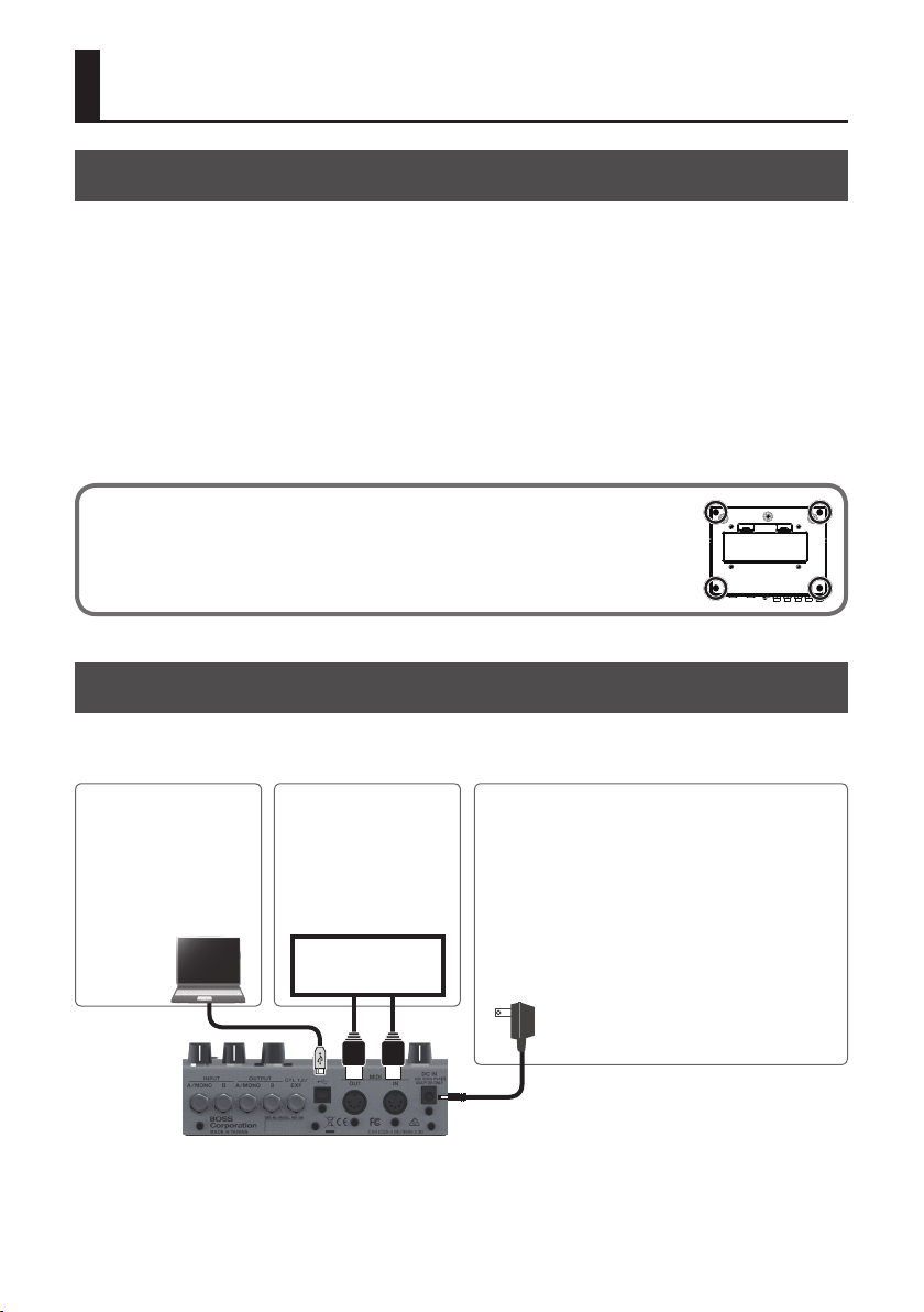
Connecting the Equipment
* To prevent malfunction and equipment failure, always turn down the volume, and turn o all
the units before making any connections.
USB (O) port
Use a commercially available
USB 2.0 cable to connect this
port to your computer.
You can synchronize with a
DAW via MIDI.
MIDI IN, OUT connectors
Connect an external MIDI
device here.
You can synchronize with
an external MIDI device
via MIDI.
MIDI device
DC IN jack
Accepts connection of an AC Adaptor (PSA-S series; sold
separately). By using an AC Adaptor, you can play without
being concerned about how much battery power you have left.
* Use only the specied AC adaptor (PSA-S series; sold
separately), and connect it to an AC outlet of the correct
voltage. Do not use any other AC adaptor, since this may
cause malfunction.
* If the AC adaptor is connected while power is on, the power
supply is drawn from the AC adaptor.
2
Page 3
Getting Ready
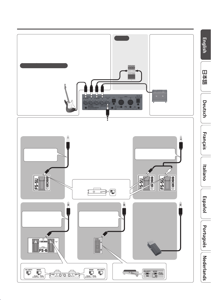
INPUT A/MONO, B jacks
Connect your electric guitar, or another instrument or eect unit, to
these jacks.
* Use the INPUT A/MONO jack and B jack when connecting a stereo-
output eects unit. Use only the INPUT A/MONO jack if you’re
using a mono source.
Turning the power on/o
The INPUT A/MONO jack doubles as the power switch. Power to the
unit is turned on when you plug into the INPUT A/MONO jack; the
power is turned o when the cable is unplugged.
When powering up:
Turn on the power to your amp
last.
When powering down:
Turn o the power to your amp
rst.
CTL 1, 2/EXP jack
You can control various parameters by connecting a footswitch (FS-5U, FS-5L, FS-6, FS-7: sold separately) or an expression pedal (such as
the EV-30, Roland EV-5; sold separately) to the CTL 1, 2/EXP jack (p. 25).
When Connecting an FS-5U
(or FS-5L)
1/4” phone type ,1/4”
phone type
POLARITY switch
MEMO
You can connect an
external eect unit and
use it in conjunction
with the MD-500’s
eects (p. 24).
INPUTOUTPUT
When Connecting Two FS-5Us
(or FS-5Ls)
Stereo 1/4” phone type
,
1/4” phone type x 2
OUTPUT A/MONO, B jacks
Connect these jacks to your
amp or monitor speakers.
If you’re using a mono setup,
use only the OUTPUT A/
MONO jack.
* Do not connect
headphones to the
OUTPUT A/MONO, B jacks.
Doing so may damage the
headphones.
CTL 1 CTL 2 CTL 1
When connecting expression
pedal
* Use only the specied
Stereo 1/4” phone type
,
Stereo 1/4” phone type
CTL 2 CTL 1
MODE/POLARITY switch
When Connecting an FS-7When Connecting an FS-6
Stereo 1/4” phone type
,
Stereo 1/4” phone type
MODE/POLARITY switch
expression pedal (EV-30,
Roland EV-5; sold separately).
By connecting any other
expression pedals, you risk
causing malfunction and/or
damage to the unit.
EXP
3
Page 4
Basic Operation
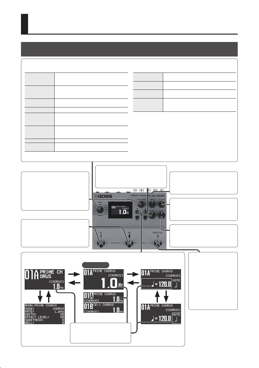
Adjusting the Eect
[MODE] knob
Selects the type of eect.
CHORUS
FLANGER
PHASER
CLASSIC-VIBE Models a Uni-vibe.
VIBRATO
TREMOLO
DIMENSION Models the Roland DIMENSION D (SDD-320).
RING MOD
[RATE/VALUE] knob
Adjusts the rate at which the eect
sound is modulated.
To make larger changes in the value,
turn the knob while pressing it.
A chorus unit that can simulate anything
from a vintage chorus unit to a chorus eect
powered by BOSS’s cutting-edge technology.
Generates a anging eect. Turn the TURBO
SW “ON” to create an even more intense
sound.
Generates a phase eect. This can also give
you the light sound of a vintage phaser.
A vibrato with a unique eect. This can also
simulate the scanner vibrato of a tonewheel
organ.
An eect that cyclically varies the volume.
This can also simulate the tremolo of a vintage
guitar amp.
Produces an unpitched sound with a metallic
character.
[PARAM 1] knob
Adjusts a parameter that is assigned to
each mode.
ROTARY
FILTER
SLICER
OVERTONE
A realistic simulation of a rotary speaker's
sound.
Lets you use the input to control the lter, or
program the lter's modulation cycle.
Repeatedly cuts the sound to produce a
variety of slice patterns.
Adds new overtones to create resonance and
depth that was not present in the original
sound.
[DEPTH] knob
Adjusts the depth to which the eect
sound is modulated.
[E. LEVEL] knob
Adjusts the volume of the eect sound.
[A] [B] switches
Switch banks/patches (p. 6).
[I] [H] buttons
Switch screens.
[H] [I]
4
Top screen
[H]
[I]
In simul mode (p. 23)
Turn the [RATE/VALUE] knob to
adjust the value.
Tempo
[H]
[I]
Note
Note length relative to
the tempo
[PARAM 2] knob
Adjusts a parameter that is assigned to
each mode.
[TAP/CTL] switch
You can press this switch
to vary the way in which
the eect is applied (p. 7).
By pressing this switch in
time with the tempo of
the song you’re playing
(tap input), you can easily
[H] [I]
set the modulation rate to
match your song.
Page 5
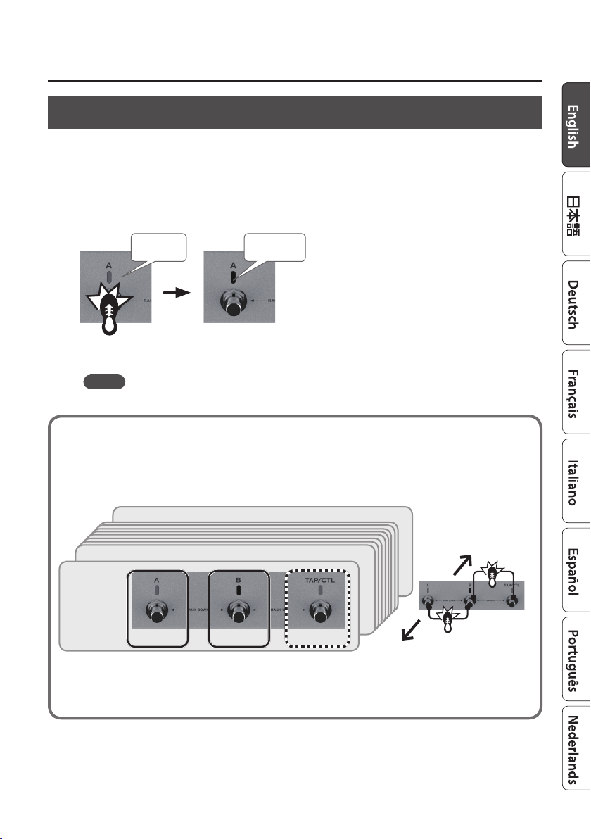
Turning Eect On/O
Patch A eect
Each time you press the [A] switch, the eect alternately turns on (lit blue) / o (unlit).
Patch B eect
Each time you press the [B] switch, the eect alternately turns on (lit blue) / o (unlit).
Blue: on Unlit: o
Press once
MEMO
You can also make settings so that patches A and B are used simultaneously (p. 22).
Patches and Banks
Settings for MODE, DEPTH, and EFFECT LEVEL are collectively called a “patch.” You can select
patches using [A], [B], and [TAP/CTL] switches (p. 22). A combination of patches A, B, and C is
called a “ bank.”
Basic Operation
BANK 99
BANK 02
BANK 01
Patch 01A Patch 01B Patch 01C
* If you want to use the [TAP/CTL] switch to select patch C, refer to “Assigning the Functions of the [A], [B], and [TAP/CTL]
Switches” (p. 22).
Bank down
Bank up
5
Page 6
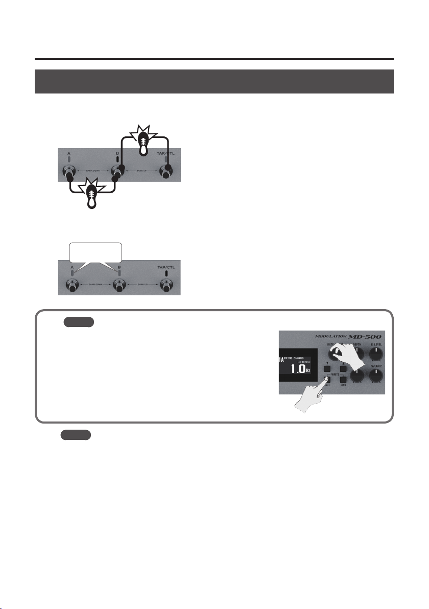
Basic Operation
Switching Banks/Patches
1. Switch banks (01–99).
Bank up (press the [B] and [TAP/CTL] switches simultaneously)
Bank down (press the [A] and [B] switches simultaneously)
2. Press a blinking switch ([A] or [B]) to switch patches.
Blinking blue
MEMO
You can recall a dierent patch by turning the [RATE/VALUE]
knob while you hold down the [EXIT] button.
MEMO
You can change the functions that are controlled by the [A], [B], and [TAP/CTL] switches; for
example, you can make the [A] switch turn eect on/o.
6
Page 7
Basic Operation
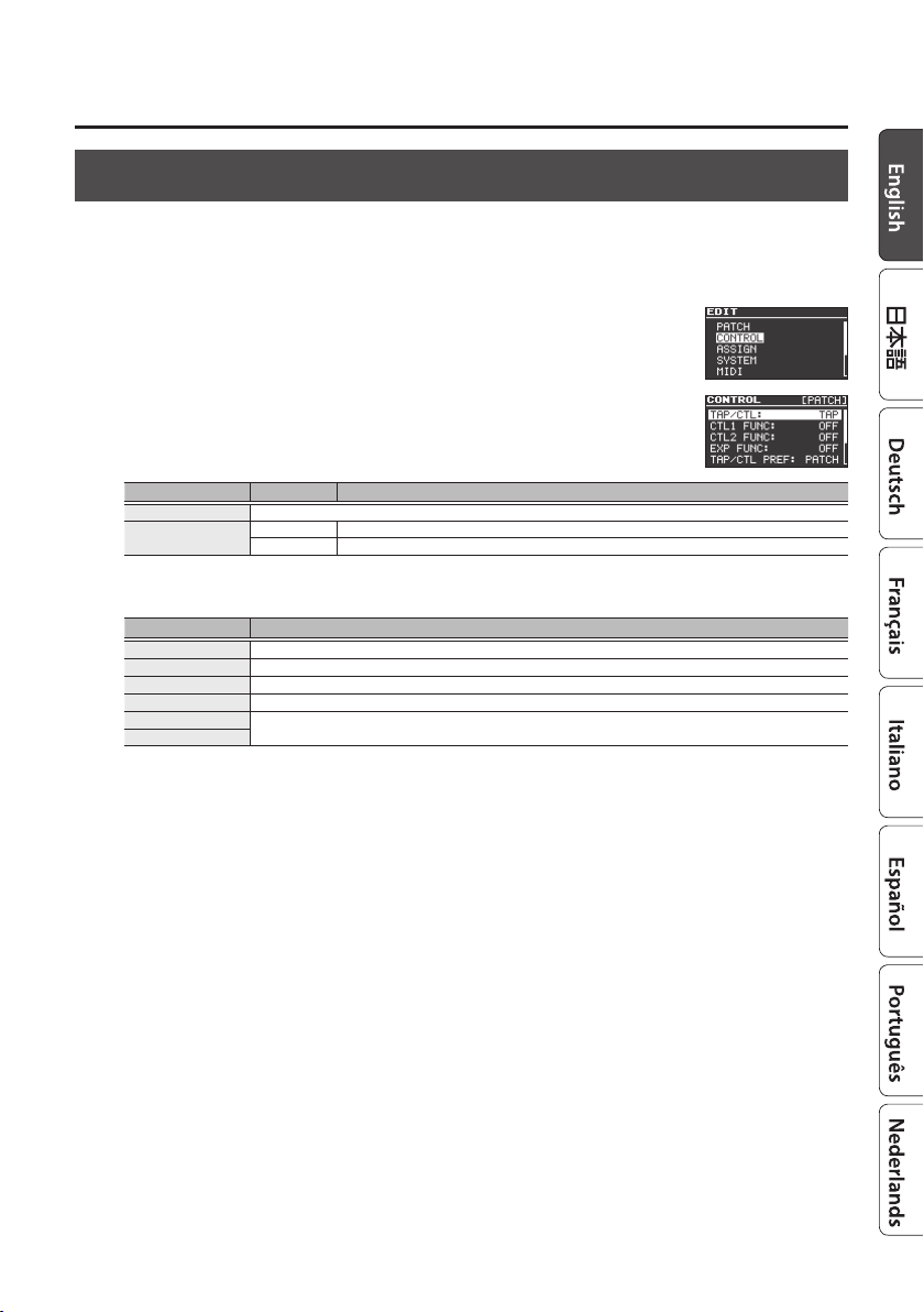
Using the [TAP/CTL] Switch to Control the Eect
By default, the [TAP/CTL] switch is used for tap input, but you can change the setting and use this
switch to vary the way in which the eect is applied.
1. Press the [EDIT] button.
2. Use the [
H
] [I] buttons to select “CONTROL” and then press the
[EDIT] button.
3. Use the [
H
] [I] buttons to select a parameter, and use the [RATE/
VALUE] knob to edit the value.
Parameter Value Explanation
TAP/CTL Species the function of the [TAP/CTL] switch.
TAP/CTL PREF
PATC H Dierent settings can be made for each patch.
SYSTEM The same settings are shared by all patches.
TAP/CTL Settings
Value Explanation
OFF No assignment.
TAP Lets you specify the modulation rate by tap input.
RESET When you press the pedal, the LFO’s phase returns to the value of INIT PHASE (p. 10).
MOMENT Outputs the eect sound only while you hold down the switch.
BANK UP
BANK DOWN
4. Press the [EXIT] button to return to the top screen.
Change banks.
7
Page 8

Editing a Patch
You can edit a variety of patch-related parameters.
1. Press the [EDIT] button.
2. Use the [
[EDIT] button.
3. Use the [
VALUE] knob to edit the value.
H
] [I] buttons to select “PATCH,” and then press the
H
] [I] buttons to select a parameter, and use the [RATE/
4. Press the [EXIT] button to return to the top screen.
* Save the edited patch as described in the procedure on “Saving a Patch” (p. 9).
Basic [EDIT] operations
Use the [H] [I] buttons to move the cursor
Use the [RATE/VALUE] knob to edit the value
[EDIT] button
[EDIT] button
[EXIT] button
Use the [H] [I] buttons
to move the cursor
8
Page 9
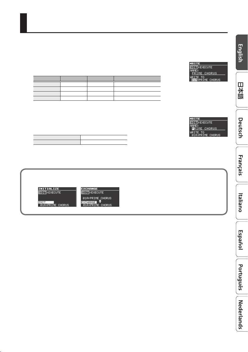
Saving a Patch
Here’s how to save a patch that you’ve edited.
1. Press the [EXIT] button and [EDIT] button simultaneously.
2. Use the [RATE/VALUE] knob to select the save-destination
number.
Bank [A] switch [B] switch [ TAP/C TL] switch
Bank 01 01A 01B 01C
Bank 02 02A 02B 02C
: : : :
Bank 99 99A 99B 99C
* Patch C can be selected only if FSW MODE (p. 22) is set to “A/B/C.”
3. Press the [
H
] button to select the patch name.
4. Edit the patch name.
[H] [I] buttons
[RATE/VALUE] knob Edit the character
Move the cursor
5. Press the [EDIT] button to save the patch.
If you decide to cancel, press the [EXIT] button.
By moving the cursor to “WRITE TO” and turning the [RATE/VALUE] knob, you can initialize a
patch (INIT) or exchange patches (EXCHANGE).
9
Page 10

Parameter List
PATCH
Parameters Common to All Modes
Parameter Value Explanation
MODE Selects the type of eect (p. 4). The same function as the [MODE] knob.
EFFECT LEVEL (*1) 0–100 Adjusts the volume of the eect sound.
DIRECT LEVEL 0–100 Adjusts the volume of the direct sound.
INIT PHASE (*2) 0–345 deg Adjusts the LFO’s phase.
TEMPO HOLD (*3) OFF, ON
Species the insert position when using the insert loop function with an external eect unit (p. 24).
INSERT SW
OUTPUT GAIN -6–+6 dB Adjusts the output level.
*1: Except when MODE is “OVERTONE”
*2: Except when MODE is “DIMENSION,” “FILTER (T-WAH G/B, PATTERN FILTER),” “SLICER” or “OVERTONE”
*3: Except when MODE is “DIMENSION,” “RING MOD,” “FILTER (T-WAH G/B),” or “OVERTONE”
OFF The insert loop function is not used.
PRE The inser t loop is connected before the patch.
POST The insert loop is connected after the patch.
Parameters for Each Mode
CHORUS
Parameter Value Explanation
TYPE
PRIME
RAT E 0.01–20.00 Hz Adjusts the rate of the chorus.
BPM 6.0–600.0
NOTE
DEPTH 0–100 Adjusts the depth of the chorus.
PRE-DELAY 0.0–40.0 ms
WAVEFORM 1–10 Adjusts the sense of modulation for the chorus.
SWEETNESS 0–100 Higher values produce a more enveloping sound.
BELL 0–100 Higher values produce a more brilliant sound.
LOW LEVEL -50–+50 Adjusts the low frequency range tone.
LOW FREQ 20.0–800 Hz Species the frequency adjusted by the LOW LEVEL setting.
HIGH LEVEL -50–+50 Adjusts the high frequency range tone.
HIGH FREQ 630–16.0 kHz Species the frequency adjusted by the HIGH LEVEL setting.
LOW CUT FLAT, 20–800 Hz
HIGH CUT 630 Hz–16.0 kHz, FLAT
OUTPUT MODE MONO, STEREO Species whether the output is mono (MONO) or stereo (STEREO).
Selects the type of chorus.
PRIME A chorus sound unique to the MD-500.
CE-1 CHORUS The chorus sound of the CE-1.
CE-1 VIBRATO The vibrato sound of the CE-1.
TRI-CHO
`–Œ
Species whether the tempo (BPM) changes or is maintained when you switch
patches. Maintaining the tempo lets you maintain the RATE setting. However,
if the NOTE setting (such as ¸ or ˙) of the newly selected patch is dierent, the
RATE also changes.
Models the SONGBIRD TSC-1380S, a three-phase chorus unit that took the world
by storm in the ‘80s.
Species the tempo.
The range of this setting depends on the RATE or NOTE value.
Adjusts the rate of the chorus, specied as a note value relative to BPM.
Adjusts the time from when the direct sound is output until when the eect
sound is output.
This sets the frequency at which the low cut lter begins to take eect. When
FLAT is selected, the low cut lter will have no eect.
This sets the frequency at which the high cut lter begins to take eect. When
FLAT is selected, the high cut lter will have no eect.
10
Page 11

Parameter List
Parameter Value Explanation
CE-1 CHORUS, CE-1 VIBRATO
RAT E 0.01–20.00 Hz Adjusts the rate of the chorus.
BPM 6.0–600.0
NOTE
DEPTH 0–100 Adjusts the depth of the chorus.
LOW LEVEL -50–+50 Adjusts the low frequency range tone.
LOW FREQ 20.0–800 Hz Species the frequency adjusted by the LOW LEVEL setting.
HIGH LEVEL -50–+50 Adjusts the high frequency range tone.
HIGH FREQ 630–16.0 kHz Species the frequency adjusted by the HIGH LEVEL setting.
PREAMP SW OFF, ON Species whether the CE-1’s preamp is simulated (ON) or not simulated (OFF).
PREAMP GAIN 1–100 Adjusts the gain of the preamp. Higher settings will produce distortion.
PREAMP LEVEL 0–100 Adjusts the volume of the preamp.
OUTPUT MODE
TRI-CHO
RATE (*1) 0.01–20.00 Hz Adjusts the rate of the chorus.
BPM (*1) 6.0–600.0
NOTE (*1)
LFO MODE
INTENSITY1 (*2) 0–100
INTENSITY3 (*2) 0–100
BRIGHT OFF, ON
LOW LEVEL -50–+50 Adjusts the low frequency range tone.
LOW FREQ 20.0–800 Hz Species the frequency adjusted by the LOW LEVEL setting.
HIGH LEVEL -50–+50 Adjusts the high frequency range tone.
HIGH FREQ 630–16.0 kHz Species the frequency adjusted by the HIGH LEVEL setting.
OUTPUT MODE MONO, STEREO Species whether the output is mono (MONO) or stereo (STEREO).
*1: Unavailable if LFO MODE is “PRESET”
*2: Shown if LFO MODE is “MANUAL” or “P+M”
`–Œ
Species the output of the chorus.
MONO Mono output.
STEREO
`–Œ
Selects the LFO mode.
PRESET The RATE is xed (4.98 Hz).
MANUAL RATE adjusts the rate of the chorus.
P+M The PRESET and MANUAL LFOs are summed.
Species the tempo.
The range of this setting depends on the RATE or NOTE value.
Adjusts the rate of the chorus, specied as a note value relative to BPM.
Direct sound is output from the OUTPUT A/MONO jack, and eect sound is
output from the B jack.
Species the tempo.
The range of this setting depends on the RATE or NOTE value.
Adjusts the rate of the chorus, specied as a note value relative to BPM.
Adjust the depth of the three-phase chorus.INTENSITY2 (*2) 0–100
Species whether the high-frequency region of the eect sound is boosted (ON)
or not boosted (OFF).
11
Page 12

Parameter List
FLANGER
Parameter Value Explanation
TYPE
RAT E 0.01–20.00 Hz Adjusts the speed of modulation.
BPM 6.0–600.0
NOTE
DEPTH 0–100 Adjusts the depth of modulation.
RESONANCE 0–100 Adjusts the amount of resonance (feedback).
MANUAL 0–100 Adjusts the center frequency at which the eect is applied.
TURBO OFF, ON If this is “ON,” a more intense eect is produced.
LOW DAMP -100–0 Adjusts the amount of feedback for the low-frequency region.
HIGH DAMP -100–0 Adjusts the amount of feedback for the high-frequency region.
LOW CUT FLAT, 20–800 Hz
HIGH CUT 630 Hz–16.0 kHz, FLAT
SEPARATION (*1) 0–180 deg Adjusts the spread. Higher settings increase the left/right spread.
STEP RATE
WAVEFORM 1–10 Selects the type of wave.
INPUT SENS 0–100
POLARITY UP, DOWN
OUTPUT MODE MONO, STEREO Species whether the output is mono (MONO) or stereo (STEREO).
*1: Unavailable if OUTPUT MODE is “MONO”
Selects the type of anger.
PRIME G For guitar
PRIME B For bass
Species the tempo.
`–Œ
OFF, ª–
`
The range of this setting depends on the RATE or NOTE value.
Adjusts the speed of modulation, specied as a note value relative to BPM.
This sets the frequency at which the low cut lter begins to take eect. When
FLAT is selected, the low cut lter will have no eect.
This sets the frequency at which the high cut lter begins to take eect. When
FLAT is selected, the high cut lter will have no eect.
Adjusts the rate of the step function which varies the rotation in a step-wise
manner. Higher settings make the change occur in smaller steps. Turn this "OFF"
if you don't want to use the step function.
The width of the sweep changes according to the input. Higher settings extend
the sweep.
Species whether the sweep extends upward (UP) or downward (DOWN) when
INPUT SENS is raised.
PHASER
Parameter Value Explanation
TYPE
PRIME G, PRIME B
RAT E 0.01–20.00 Hz Adjusts the speed of rotation.
BPM 6.0–600.0
NOTE
DEPTH 0–100 Adjusts the depth of the rotation eect.
RESONANCE 0–100 Adjusts the amount of resonance (feedback).
MANUAL 0–100 Adjusts the center frequency at which the rotation eect is applied.
LOW DAMP -100–0 Adjusts the amount of feedback for the low-frequency region.
HIGH DAMP -100–0 Adjusts the amount of feedback for the high-frequency region.
LOW CUT FLAT, 20–800 Hz
HIGH CUT 630 Hz–16.0 kHz, FLAT
SEPARATION 0–180 deg Adjusts the spread. Higher settings increase the left/right spread.
WAVEFORM 1–10 Selects the type of wave.
INPUT SENS 0–100
POLARITY UP, DOWN
STAGE 2, 4, 8, 16, 24 Selects the structure of the phaser.
12
Selects the type of phaser.
PRIME G For guitar
PRIME B For bass
SCRIPT M odels the MXR Phase 90 which was manufactured during the ‘70s.
Species the tempo.
`–Œ
The range of this setting depends on the RATE or NOTE value.
Adjusts the speed of rotation, specied as a note value relative to BPM.
This sets the frequency at which the low cut lter begins to take eect. When
FLAT is selected, the low cut lter will have no eect.
This sets the frequency at which the high cut lter begins to take eect. When
FLAT is selected, the high cut lter will have no eect.
The width of the sweep changes according to the input. Higher settings extend
the sweep.
Species whether the sweep extends upward (UP) or downward (DOWN) when
INPUT SENS is raised.
Page 13

Parameter List
Parameter Value Explanation
STEP RATE
Bi-PHASE OFF, ON
OUTPUT MODE MONO, STEREO Species whether the output is mono (MONO) or stereo (STEREO).
SCRIPT
RAT E 0.01–20.00 Hz Adjusts the speed of rotation.
BPM 6.0–600.0
NOTE
DEPTH 0–100 Adjusts the depth of the rotation eect.
OFF, ª–
`–Œ
`
Adjusts the rate of the step function which varies the rotation in a step-wise
manner. Higher settings make the change occur in smaller steps. Turn this “OFF”
if you don’t want to use the step function.
Species whether the two phase shift circuits are connected in series (ON) or
not (OFF).
Species the tempo.
The range of this setting depends on the RATE or NOTE value.
Adjusts the speed of rotation, specied as a note value relative to BPM.
CLASSIC-VIBE
Parameter Value Explanation
TYPE
RAT E 0.01–20.00 Hz Adjusts the rate at which the eect is applied.
BPM 6.0–600.0
NOTE
DEPTH 0–100 Adjusts the depth at which the eect is applied.
Selects the type of output.
CHORUS Direct sound and eect sound are mixed and output.
VIBRATO Only eect sound is output.
Species the tempo.
The range of this setting depends on the RATE or NOTE value.
`–Œ
Adjusts the rate at which the eect is applied, specied as a note value relative
to BPM.
VIBRATO
Parameter Value Explanation
TYPE
PRIME
RAT E 0.01–20.00 Hz Adjusts the rate of vibrato.
BPM 6.0–600.0
NOTE
DEPTH 0–100 Adjusts the depth at which vibrato is applied.
COLOR 0–100 Higher settings produce a more complex modulation.
TRIGGER OFF, ON Turns the vibrato on/o.
RISE TIME 0–100
ENVELOPE SENS 0–100
WAVEFORM 1–10 Selects the type of wave.
INPUT SENS 0–100
SCANNER
SCAN SPEED 0.01–20.00 Hz Adjusts the speed of vibrato.
BPM 6.0–600.0
NOTE
MODE
Selects the type of vibrato.
PRIME A vibrato unique to the MD-500. A wide range of settings are possible.
SCANNER Simulates the scanner vibrato of a tonewheel organ.
Species the tempo.
`–Œ
`–Œ
Selects the SCANNER mode.
V1–V3 Applies vibrato. Higher values produce a deeper eect.
C1–C3
The range of this setting depends on the RATE or NOTE value.
Adjusts the rate of vibrato, specied as a note value relative to BPM.
Species the time from when trigger turns on until the specied vibrato eect
is obtained.
Adjusts the time over which the vibrato depth reaches the maximum according
to the input.
The vibrato depth changes according to the input. If this is set to “0,” vibrato is
applied at a xed depth regardless of the input. With higher values, less vibrato is
applied for louder input.
Species the tempo.
The range of this setting depends on the SCAN SPEED or NOTE value.
Adjusts the speed of vibrato, specied as a note value relative to BPM.
Applies chorus. Higher values produce a deeper eect.
Mixes eect sound with direct sound, adding depth to the sound.
13
Page 14

Parameter List
TREMOLO
Parameter Value Explanation
TYPE
PRIME T, PRIME P
RAT E 0.01–20.00 Hz Adjusts the rate of the tremolo.
BPM 6.0–600.0
NOTE
DEPTH 0–100 Adjusts the tremolo depth.
TRIGGER OFF, ON Turns the tremolo on/o.
RISE TIME 0–100
ENVELOPE SENS 0–100
WAVEFORM 1–100 Selec ts the type of wave.
INPUT SENS 0–100
TWIN, DELUXE
SPEED 0.01–20.00 Hz Adjusts the speed of the tremolo.
BPM 6.0–600.0
NOTE
INTENSITY 0–100 Adjusts the tremolo depth.
Selects the type of tremolo.
PRIME T A tremolo unique to the MD-500. A wide range of settings are possible.
PRIME P
TWIN Models the tremolo of the Fender Twin Reverb.
DELUXE Models the tremolo of the Fender Deluxe Reverb.
`–Œ
`–Œ
Alternates the volume of the left and right channels; when played in stereo, this
produces the impression that the sound is moving back and forth between the
left and right speakers (pan).
* This does not produce the intended eect unless you use stereo output.
Species the tempo.
The range of this setting depends on the RATE or NOTE value.
Adjusts the speed of the tremolo, specied as a note value relative to the BPM.
Species the time from when trigger turns on until the specied tremolo eect
is obtained.
Adjusts the time over which the tremolo depth reaches the maximum according
to the input.
The tremolo depth changes according to the input. If this is set to “0,” tremolo is
applied at a xed depth regardless of the input. With higher values, less tremolo
is applied for louder input.
Species the tempo.
The range of this setting depends on the SPEED or NOTE value.
Adjusts the speed of the tremolo, specied as a note value relative to the BPM.
DIMENSION
Parameter Value Explanation
DIMENSION MODE
MODE 1–4 SW OFF, ON
MODE 5 SW OFF, ON A mode that is unique to the MD-500 and is not found on the SDD-320.
OUTPUT MODE MONO, STEREO Species whether the output is mono (MONO) or stereo (STEREO).
Selects the mode of the Roland DIMENSION D (SDD-320).
1–4, USER
Models the mode switches of the Roland DIMENSION D (SDD-320). If this is set to
“USER,” you can freely combine the various mode switches.
Turn each mode switch on/o.
Each switch can be turned on simultaneously.
RING MOD
Parameter Value Explanation
FREQUENCY 82.4–3136.0 Hz Adjusts the oscillation frequency of the internal oscillator.
FREQUENCY MOD RATE 0.01–20.00 Hz Adjusts the rate at which the internal oscillator is modulated.
FREQUENCY MOD DEPTH 0–100 Adjusts the depth to which the internal oscillator is modulated.
INTELLIGENT OFF, GUITAR, BASS
14
Varies the oscillator frequency according to the pitch of the input sound,
producing a sound with a dierent sense of pitch than usual.
“GUITAR” is for guitar, and “BASS” is for bass.
* This eect will not produce the expected eect unless the pitch of the guitar
sound is correctly detected. We recommend that you use it with single notes.
Page 15

Parameter List
ROTARY
Parameter Value Explanation
SPEED SELECT SLOW, FAST Switches the speaker rotation speed between SLOW (slow) and FAST (fast).
SLOW RATE 0.01–20.00 Hz Adjusts the speed of rotation when SPEED SELECT is set to SLOW.
FAST RATE 0.01–20.00 Hz Adjusts the speed of rotation when SPEED SELECT is set to FAST.
RISE TIME 1–100
FALL TIME 1–100
MIC DISTANCE 0–100 Adjusts the distance between the horn/rotor and the mic.
ROTOR/HORN 100:0–0:100 Adjusts the volume balance between the horn and rotor.
DRIVE 0–100 Adjusts the amount of distortion in the preamp.
Adjusts the transition time over which the rotation speed changes when SPEED
SELECT is switched from SLOW to FAST.
Adjusts the transition time over which the rotation speed changes when SPEED
SELECT is switched from FAST to SLOW.
FILTER
Parameter Value Explanation
TYPE
A-WAH G, A-WAH B
RAT E 0.01–20.00 Hz Adjusts the rate of the wah.
BPM 6.0–600.0
NOTE
FILTER MODE
DEPTH 0–100 Adjusts the wah depth.
FREQUENCY 0–100 Adjusts the center frequency of the wah eect.
RESONANCE 0–100
WAVEFORM
T-WAH G, T-WAH B
FILTER MODE
POLARITY
SENS 0–100
FREQUENCY 0–100 Adjusts the center frequency of the wah eect.
RESONANCE 0–100 Adjusts how the wah eect is applied in the region of the center frequency.
DECAY 0–100 Adjusts the rate at which the lter is moved.
Selects the type of wah eect and lter.
A-WAH G
A-WAH B Automatically produces a wah eect by cyclically modulating the lter (for bass).
T-WAH G
T-WAH B
PAT TERN Lets you freely program how the lter changes.
`–Œ
Selects the wah mode.
LPF Low pass lter. Passes only the low-frequency region.
HPF High pass lter. Passes only the high-frequency region.
BPF Band pass lter. Passes only the specied frequency region.
SIN, TRI, SQR, SAW-UP,
SAW-DOWN, RAMP
Selects the lter mode.
LPF Low pass lter. Passes only the low-frequency region.
HPF High pass lter. Passes only the high-frequency region.
BPF Band pass lter. Passes only the specied frequency region.
Selects the direction in which the lter changes according to the input.
DOWN The lter moves toward a lower frequency.
UP The lter moves toward a higher frequency.
Automatically produces a wah eect by cyclically modulating the lter
(for guitar).
Produces a wah eect by modulating the lter according to the volume of the
input signal (for guitar).
Produces a wah eect by modulating the lter according to the volume of the
input signal (for bass).
Species the tempo.
The range of this setting depends on the RATE or NOTE value.
Adjusts the rate of the wah, specied as a note value relative to the BPM.
Adjusts how the wah eect is applied in the region of the center frequency.
Higher values boost the lter eect, producing a strongly distinctive character. A
value of “50” produces the typical wah sound.
Selects the type of wave.
Species the sensitivity with which the lter moves in the direction specied by
the POLARITY setting. Higher values increase the response; with a setting of “0,”
the wah eect does not respond to your picking.
15
Page 16

Parameter List
Parameter Value Explanation
PAT TERN FILTER
RAT E 0.01–20.00 Hz Adjusts the rate of the lter.
BPM 6.0–600.0
NOTE
PAT TERN PAT1–PAT10, USER
STEP NUMBER 8, 12, 16, 24 Selects the number of steps into which the sound is divided.
FILTER MODE
RESONANCE 0–100 Adjusts the resonance.
TRANSITION 0–100 Adjusts the time (smoothness) of the transition between steps.
STEP1–STEP24 FREQ (*1) 0–100 Adjusts the frequency of each step.
*1: Shown if PAT TERN is “USER”
`–Œ
Selects the lter mode.
LPF Low pass lter. Passes only the low-frequency region.
HPF High pass lter. Passes only the high-frequency region.
BPF Band pass lter. Passes only the specied frequency region.
Species the tempo.
The range of this setting depends on the RATE or NOTE value.
Adjusts the rate of the lter, specied as a note value relative to the BPM.
Selects the pattern.
PAT1–10: Selec ts a preset pattern.
USER: Lets you create an original pattern.
SLICER
Parameter Value Explanation
RAT E 0.01–20.00 Hz Adjusts the rate at which the sound is sliced.
BPM 6.0–600.0
NOTE
PAT TERN P1–30, H1–H20, USER
FX TYPE (*1)
STEP NUMBER (*1) 8, 12, 16, 24
STEP1–STEP24 LENGTH (*1) 0–100
STEP1–STEP24 LEVEL (*1) 0–100 Adjusts the volume of each step.
STEP1–STEP24 BAND (*1) THRU, BAND1–BAND6
STEP1–STEP24 EFFECT (*1) 0–100
ATT ACK 0–100 Adjusts the volume of the attacks for the slice pattern.
DUTY (*2) 1–99 Adjusts the duration of the sound for the slice pattern.
OUTPUT MODE
*1: Shown if PAT TERN is “USER”
*2: Unavailable if PAT TERN is set to “USER.”
`–Œ
Selects the eect type.
OFF Eect o
PITCH Pitch change
FLANGER Flanger
PHASER Phaser
SWEEP Sweep lter
FILTER Filter
RING Ring modulator
MONO, FIXED, RANDOM,
PngPong, AUTO
Species the tempo.
The range of this setting depends on the RATE or NOTE value.
Adjusts the rate at which the sound is sliced, specied as a note value relative
to the BPM.
Selects the slice pattern at which the sound is sliced.
P1–30, H1–H20: Selects a preset pattern.
USER: Lets you create an original pattern.
Selects the number of steps that play back as a pattern.
For example, if this is “8,” one measure is equally divided into eight steps for
playback.
Adjusts the length (duration) of each step.
0: No sound is heard.
1–99: The sound is heard for the duration specied here.
100: The sound is connected with the next step.
Species how the bandwidth of each step is limited.
THRU: The bandwidth is not limited.
BAND1–BAND6: Smaller values allow a higher bandwidth to pass.
Adjusts the volume of the eect sound for each step.
If FX TYPE is set to "PITCH," this adjusts the pitch (-12–+12).
Selects how output occurs.
16
Page 17

Parameter List
OVERTONE
Parameter Value Explanation
TYPE
OVERTONE
LOWER LEVEL 0–100 Adjusts the volume of the overtones one octave below.
UPPER LEVEL 0–100 Adjusts the volume of the overtones one octave above.
UNISON LEVEL 0–100
DETUNE 0–100 Adjusts the depth to which the entire eect sound is modulated.
LOW -50–+50 Adjusts the low frequency range tone.
HIGH -50–+50 Adjusts the high frequency range tone.
DETUNE
PITCH 1
PITCH 2
EFFECT LEVEL 1
EFFECT LEVEL 2
Selects the type of overtones.
OVERTONE Thickens the sound by adding overtones.
DETUNE Thickens the sound by adding slightly pitch-shifted sound.
Adjusts the volume of added sound whose pitch is slightly shifted relative to the
direct sound.
-50–+50 Adjusts the pitch (1-cent units).
0–100 Adjusts the volume of the eect sound.
17
Page 18

Parameter List
CONTROL
You can specify the functions of the [TAP/CTL] switch and of a footswitch or expression pedal
connected to the CTL 1,2/EXP jack.
5 “Using the [TAP/CTL] Switch to Control the Eect” (p. 7)
5 “Assigning a Function to an External Pedal” (p. 25)
ASSIGN
ASSIGN INPUT SENS
Parameter Value Explanation
ASGN INPUT SENS 0–100 Adjusts the input sensitivity when “INPUT” is selected for SRC.
ASSIGN 1–8
Parameter Value Explanation
SW OFF, ON Turns the ASSIGN 1–8 on/o.
SRC (SOURCE)
Species the controller (source).
TAP/CTL [TAP/CTL] switch.
EXP PDL
(EXP PEDAL)
CTL1, 2 PDL External footswitch connected to the CTL 1,2/EXP jack.
INT PDL
WAVE PDL
External expression pedal (EV-30, EV-5 etc.; sold separately) connected to the
CTL 1,2/EXP jack.
Internal pedal
The virtual expression pedal will begin operating when started
by the specied trigger (TRIGGER), modifying the parameter
specied by “ TARGET.”
For details on the parameters that can be assigned to the internal
pedal, refer to “TIME” and “CURVE” (p. 19)
Wave pedal
The virtual expression pedal will cyclically modify the parameter specied by
“TARGET” in a xed wave form.
INPUT
(INPUT LEVEL)
CC#1–31, CC#64–95 Controller number from an external MIDI device
Species the operation of the controller.
MODE (SOURCE MODE)
TRG (TARGET) This selects the parameter to be changed.
MIN (TARGET MIN)
MAX (TARGET MAX)
MOMENT
TOGGLE
Species the range of change for the parameter. The values will depend on the parameter that’s assigned by
“TARGET.”
The assigned target parameter will change according to the input level.
* If you want to adjust the input sensitivity, set the SENS (INPUT SENS).
The value will normally be OFF (minimum value), and will be ON
(maximum value) only while the control is being operated.
* If you want to use the internal pedal or wave pedal, set to “MOMENT.”
The value will toggle between OFF (minimum) and ON (maximum) each time the
control is operated.
18
Page 19

Parameter Value Explanation
ACT LOW 0–126
ACT HIGH 0–127
–
WAVE RATE (*1)
WAVE FORM (*1) SAW, TRI, SIN
TRIGGER
(INT PEDAL TRIGGER)
(*2)
TIME
(INT PEDAL TIME)
(*2)
CURVE
(INT PEDAL CURVE)
(*2)
0–100,
* If, due to the tempo, the time is longer than the range of allowable settings, it is then synchronized to a
period either 1/2 or 1/4 of that time.
Species how the motion of the internal pedal will be triggered.
PAT CNG
(PATCH CHANGE)
EXP LOW
EXP MID
EXP HIGH
CTL1, 2 PDL
CC#1–#31
CC#64–#95
0–100
LINEAR,
SLOW (SLOW RISE),
FAST (FAST RISE)
Within the operating range of the source, this species the range that will
control the target parameter.
The target parameter will be controlled within the range specied. Normally, you
should leave ACT LOW at “0” and ACT HIGH at “127.”
Species the time for one cycle of the wave pedal.
Select one of the following to specify the change produced by the wave pedal.
SAW
This is activated when a patch is selected.
This is activated when an external expression pedal connected to the CTL 1,2/
EXP jack is set to the minimum position.
This is activated when the external expression pedal connected to the CTL 1,2/
EXP jack is moved through the middle position.
This is activated when the external expression pedal connected to the CTL 1,2/
EXP jack is set to the maximum position.
This is activated when an external footswitch connected to the CTL 1,2/EXP jack
is operated.
This is activated when a control change is received.
This species the time over which the internal pedal will move from the toeraised position to the toe-down position.
Select one of the following curves to specify the change produced by the
internal pedal.
LINEAR SLOW FAST
Parameter List
TRI
SIN
*1: SRC=WAVE PDL only
*2: SRC=INT PDL only
19
Page 20

Parameter List
BANK
You can specify how patches A and B are connected and output when using simul mode.
5 “Using Two Patches Simultaneously (Simul Mode)” (p. 23)
SYSTEM
Parameter Value Explanation
CONTRAST 1–16 Adjusting the contrast of the display
INSERT LOOP OFF, ON Species whether the insert loop function (p. 24) is used (ON) or not used (OFF).
BANK MODE
BANK EXTENT MIN 01–99 Sets the lower limit for the banks.
BANK EXTENT MAX 01–99 Sets the upper limit for the banks.
KNOB LOCK OFF, ON Species whether knob operations are disabled (ON) or not disabled (OFF).
KNOB MODE IMMEDIATE, HOOK
BYPASS BUFFERED, TRUE Species how the bypass sound is output (buered bypass or true bypass).
PEDAL ACT PUSH, RELEASE
FSW MODE Species how the footswitch is used (p. 22).
USB MODE Species the USB operating mode (p. 27).
Species the timing at which the patch is changed when you change banks.
WAIT
IMMEDIATE Operation immediately switches to the next patch when you switch banks.
Switching the bank only changes the indication of the screen, and does not
switch the patch at that point. When you press the [A] or [B] switch, the bank
and number are nalized, and operation switches to the next patch.
When you move a knob, this setting species whether control data for that
knob position is always output (IMMEDIATE) or is output only after the knob
position has passed through the current value of the parameter (HOOK).
Species whether the operation occurs when you press the [A], [B], or [TAP/CTL]
switch or when you release the switch.
MIDI
Parameter Value Explanation
Rx CHANNEL Ch.1–16, OFF
Tx CHANNEL Ch.1–16, Rx, OFF
PC IN OFF, ON Species whether program changes are received.
PC OUT OFF, ON Species whether program changes are transmitted.
BANK SEL OUT MSB, M+L
CC IN OFF, ON Species whether control changes are received.
CC OUT OFF, ON Species whether control changes are transmitted.
Species the receive channel.
If this is “OFF,” MIDI messages are not received.
Species the transmit channel.
If this is “OFF,” MIDI messages are not transmitted.
Species the bank select message that is transmitted simultaneously with the
program change.
If you select MSB, only MSB (CC#0) is transmitted. If you select M+L, both MSB
and LSB (CC#32) are transmitted.
20
Page 21

Parameter Value Explanation
RATE CC
DEPTH CC [DEPTH] knob
E.LEVEL CC [E. LEVEL] knob
PARAM 1 CC [PARAM 1] knob
PARAM 2 CC [PARAM 2] knob
EFFECT SW
EFFECT A SW
EFFECT B SW
CTL1 CC External CTL1 switch
CTL2 CC External CTL2 switch
EXP CC External EXP pedal
SYNC
REALTIME SRC
MIDI IN->OUT
USB IN->OUT
DEVICE ID 1–32
OFF, CC#1–31, 64–95
Selects the tempo clock input that is used for synchronization.
INTERNAL Synchronizes to the internal tempo.
EXT (USB) Synchronizes to the tempo from the USB port.
EXT (MIDI) Synchronizes to the tempo from the MIDI IN connector.
AUTO
Selects the source of the realtime messages that are transmitted from the MIDI OUT connector or the USB
port.
INT Internal realtime messages are the source.
USB Realtime messages from the USB port are the source.
MIDI Realtime messages from the MIDI IN connector are the source.
Species the connector to which MIDI messages received from the MIDI IN connector and the USB port are
output.
OFF MIDI messages are not output.
USB MIDI messages are output to the USB port.
MIDI MIDI messages are output to the MIDI OUT connector.
U+M MIDI messages are output to the USB por t and the MIDI OUT connector.
[RATE] knob
Species the controller
number that switches
between eect-on and
bypass.
Normally synchronizes to the internal tempo, but if MIDI clock is being input
from the MIDI IN connector or the USB port, the tempo is synchronized to MIDI
clock (AUTO).
If the MD-500 is a slave device, choose the “AUTO” setting.
Sets the MIDI Device ID used for transmitting and receiving System Exclusive
messages.
Parameter List
Species the controller number of the
corresponding knobs or switches.
The parameters that can be controlled dier
depending on the mode.
MEMO
For details on MIDI, refer to “MIDI
Implementation” (PDF).
http://www.boss.info/manuals/
MIDI PC MAP
Parameter Value Explanation
BNK-PC# 1:001–3:128 01A–99C Species the program number that corresponds to each patch number.
21
Page 22

Convenient Functions
Assigning the Functions of the [A], [B], and [TAP/CTL] Switches
1. Press the [EDIT] button.
2. Use the [
H
] [I] buttons to select “SYSTEM” and then press the
[EDIT] button.
3. Use the [
H
] [I] buttons to select “FSW MODE,” and use the [RATE/
VALUE] knob to select the mode.
Mode Explanation
NORMAL
A/B/C
A/B SIMUL
SW DN/UP
Use the [A] and [B] switches to select patch A or patch B, and use the [TAP/CTL]
switch for tap input.
Use the [TAP/CTL] switch to select patch C.
* In this case, you can’t use the [TAP/CTL] switch to change how the eect is
applied.
Patches A and B can be used simultaneously (p. 23). Press the unlit [A] or [B]
switch to make both light.
Use the [A] switch to turn eect on/o, and use the [B] switch and [TAP/CTL]
switch to change patches.
4. Press the [EXIT] button to return to the top screen.
22
Page 23

Convenient Functions
Using Two Patches Simultaneously (Simul Mode)
If FSW MODE is set to “A/B SIMUL,” you can use two patches A and B simultaneously (simul mode).
1. Set FSW MODE to “A/B SIMUL” (p. 22).
2. Press the unlit [A] or [B] switch to make them both light.
Now you can use two patches simultaneously.
MEMO
5 The patch that’s selected in the screen (selected by the [I] [H] buttons) is the patch that
your editing will aect.
5 The TAP/CTL (p. 7) and external footswitch setting (p. 25) apply to both patches A and B.
The lit/blinking state of the [TAP/CTL] switch follows the setting of the patch that’s selected
in the screen.
Simul mode settings (BANK)
Here’s how to specify how patches A and B are connected and output when in simul mode.
1. Press the [EDIT] button.
2. Use the [
button.
3. Use the [
VALUE] knob to edit the value.
Parameter Value Explanation
CONNECTION
OUTPUT MODE (*1)
INSERT SW
SYNC (*3) OFF, ON
*1: Shown if CONNECTION is “PARALLEL”
*2: Shown if CONNECTION is “SERIES”
*3: Not available for modes that do not have RATE or BPM
H
] [I] buttons to select “BANK,” and then press the [EDIT]
H
] [I] buttons to select a parameter, and use the [RATE/
Species how patches A and B are connected.
SERIES
PARALLEL Patches A and B are connected in parallel.
Species how sound is output from the OUTPUT A/MONO and B jacks.
MIX Patches A and B are mixed and output.
A/B
Species the connection position at which an external eect unit is inserted by
the insert loop function (p. 24).
OFF Not connected.
PRE Connected before patches A and B.
POST Connected after patches A and B.
MIDDLE (*2) Connected between patches A and B.
Patches A and B are connected in series, in the order A0B.
Sound that is input to the INPUT A/MONO jack passes through
patch A and is output to the OUTPUT A/MONO jack.
Sound that is input to the INPUT B jack passes through patch B
and is output to the OUTPUT B jack.
Selects whether the tempo of patch B is synchronized to the
tempo of patch A (ON) or is not synchronized (OFF).
NOTE can be adjusted for each patch.
Selected patch
4. Press the [EXIT] button to return to the top screen.
23
Page 24

Inserting an External Eect Unit
You can connect an external eect unit between the OUTPUT A jack and INPUT B jack, and use it in conjunction with the MD-500’s eect
(insert loop function).
You can also change the connection order of the eects.
(Example)
AMP
MD-500
[MODE]
CHORUS
Guitar
INPUTOUTPUT
Guitar
Setting the Insert Loop Function
Turning the insert loop function on
1. Press the [EDIT] button.
2. Use the [
[EDIT] button.
3. Use the [
[RATE/VALUE] knob to turn the setting “ON.”
4. Press the [EXIT] button to return to the top screen.
Specifying the connection position of the external eect unit
1. Press the [EDIT] button.
2. Use the [
[EDIT] button.
3. Use the [
VALUE] knob to edit the value.
Value Explanation
PRE Connect before the MD-500's eect.
POST Connect after the MD-500's eect.
H
] [I] buttons to select “SYSTEM,” and then press the
H
] [I] buttons to select “INSERT LOOP,” and use the
H
] [I] buttons to select “PATCH,” and then press the
H
] [I] buttons to select “INSERT SW,” and use the [RATE/
AMP
4. Press the [EXIT] button to return to the top screen.
* Save the edited patch as described in “Saving a Patch” (p. 9).
MEMO
You can also use the insert loop function in simul mode (p. 23).
24
Page 25

Assigning a Function to an External Pedal
You can assign a function to a footswitch (sold separately: FS-5U, FS-5L, FS-6, FS-7) or expression
pedal (sold separately: EV-30, Roland EV-5 etc.) connected to the CTL 1,2/EXP jack.
1. Press the [EDIT] button.
2. Use the [
H
] [I] buttons to select “CONTROL,” and then press the
[EDIT] button.
3. Use the [
H
] [I] buttons to select a parameter, and use the [RATE/
VALUE] knob to edit the value.
Parameter Value Explanation
CTL 1/2 FUNC Species the function of a footswitch connected to the CTL 1,2/EXP jack.
EXP FUNC Species the function of an expression pedal connected to the CTL 1,2/EXP jack.
TRG MIN
TRG MAX
CTL 1/2 PREF
EXP PREF
Specify the minimum value (MIN) and maximum value (MAX) of the parameter that is controlled by the
expression pedal. The values depend on the parameter that is assigned in EXP FUNC.
PATC H Dierent settings can be made for each patch.
SYSTEM The same settings are shared by all patches.
CTL1 FUNC and CTL2 FUNC Settings
Value Explanation
OFF No assignment.
TAP Lets you specify the modulation rate by tap input.
RESET Pressing the pedal returns the LFO phase to the INIT PHASE (p. 10) value.
MOMENT Outputs the eect sound only while you hold down the switch.
BANK UP
BANK DOWN
Change banks.
EXP FUNC Settings
Value Explanation
OFF No function is assigned. Select this if you’re using the ASSIGN1–8 setting (p. 18).
RAT E Adjusts the rate at which the eect sound is modulated.
DEPTH Adjusts the depth to which the eect sound is modulated.
E.LEVEL Adjusts the volume of the eect sound.
PARAM1/2 Adjust the parameters that are assigned to the [PARAM 1] knob and the [PARAM 2] knob.
4. Press the [EXIT] button to return to the top screen.
25
Page 26

Synchronizing with a DAW or External MIDI Device
You can synchronize your MD-500 performance with a computer or an external MIDI device by
sending and receiving MIDI messages.
For example, an external MIDI device or DAW could switch patches on the MD-500 or control its
tempo.
Connection Example
DAW
External MIDI device
MIDI Messages That Can Be Transmitted and Received
Patch changes
Bank select (CC#0, #32) and program change
Synchronization
Tempo clock (F8)
Must be ON
Patch data
System exclusive messages
Other messages
Switch, knob MIDI message Value R emarks
[RATE/VALUE] knob Controller Number 17
[DEPTH] knob Controller Number 18
[E. LEVEL] knob Controller Number 19
[PARAM 1] knob Controller Number 20
[PARAM 2] knob Controller Number 21
CTL 1 switch Controller Number 80
CTL 2 Switch Controller Number 81
EXP pedal Controller Number 16 0–127 –
Eect on, Bypass Controller Number 27 ON, OFF
Eect A on, Bypass Controller Number 28 ON, OFF ON = Eect (patch A) on, OFF = Bypass
Eect B on, Bypass Controller Number 29 ON, OFF ON = Eect (patch B) on, OFF = Bypass
26
0–127 –
0, 127
Transmits “127” when pressed, “0” when
released
ON = Eect on, OFF = Bypass
In simul mode, this turns the selected
patch on/o.
Page 27

Synchronizing with a DAW or External MIDI Device
MIDI Routing
For details on how to set the MIDI parameters, refer to “Basic [EDIT] operations” (p. 8).
Main Setting Items
Item Parameter Explanation
Synchronization source SYNC
Realtime messages REALTIME SRC
MIDI message output
destination
MIDI IN->OUT
USB IN->OUT
Species whether the synchronization source is the MD-500
(INTERNAL), USB, or an external device connected via
MIDI.
Species whether realtime messages generated by the MD-500 are transmitted, and
whether realtime messages received via the MIDI IN connector or the USB port are
transmitted.
Species the MIDI messages that are transmitted from
the MIDI OUT connector.
Species the MIDI messages that are transmitted from
the USB port.
If you experience problems connecting with your DAW
Normally, you don’t need to install a driver in order to connect the MD-500 to your computer.
However, if some problem occurs, or if the performance is poor, using the BOSS original driver
may solve the problem.
In this case, setting “USB MODE” to “VENDOR” on the MD-500, install the
driver on your personal computer.
For details on downloading and installing the BOSS original driver, refer
to the BOSS website. For further details, refer to the Readme.htm le that
comes with the download.
&
http://www.boss.info/support/
The program you need to use, and the steps you need to take to install the USB driver will
dier depending on your computer setup, so please carefully read and refer to the Readme.
htm le that comes with the download.
27
Page 28

Restoring the Factory Default Settings
Here’s how to reset the settings to their factory state. If you like, you can also reset the system
settings or just a specic range of patches.
1. Press the [EDIT] button.
2. Use the [
the [EDIT] button.
H
] [I] buttons to select “FACTORY RESET,” and then press
3. Use “FROM” and “TO” to specify the range that you want to reset.
Parameter Value Explanation
FROM
TO
SYSTEM System parameter settings.
01A–99C Settings for Patches.
BANK01–99 Settings for Banks (Patch A–C, BANK parameters).
4. Press the [EDIT] button.
A conrmation message appears.
5. Press the [EDIT] button to reset the settings.
If you decide to cancel without resetting, press the [EXIT] button.
Transmitting Data to an External MIDI Device
You can use Exclusive messages to set another MD-500 to the same settings or to save eect sound
settings to MIDI sequencers and other such devices. This transmission of data is referred to as bulk
dump.
1. Press the [EDIT] button.
2. Use the [
press the [EDIT] button.
3. Use “FROM” and “TO” to specify the range that you want to reset.
Parameter Value Explanation
FROM
TO
H
] [I] buttons to select “MIDI BULK DUMP,” and then
SYSTEM System parameter settings.
01A–99C Settings for Patches.
BANK01–99 Settings for Banks (Patch A–C, BANK parameters).
TEMP Current eect settings in the panel display.
4. Press the [EDIT] button.
The bulk dump is executed.
28
Page 29

Troubleshooting
Problem Items to check Action
Power does not turn on
No sound is output
Footswitch does not change sounds as
you expect
Is your guitar correctly connected to the
INPUT A/MONO jack?
Could the batteries be low? Install fresh batteries.
Is the specied PSA-S series AC adaptor
connected correctly?
Could the insert loop function be
assigned?
Is the SYSTEM: FSW MODE (p. 22) setting
correct?
Check the connection once again.
Check the connection once again.
If the insert loop function is on, there will
be no sound unless the external eect
unit is correctly connected and its power
is on (p. 24).
The FSW MODE (p. 22) setting determines
what happens when you press the [A], [B],
and [TAP/CTL] switches. Check the setting.
Main Specications
BOSS MD-500: Modulation
Power Supply
Current Draw 225 mA
Battery Life for Continuous
Use
Dimensions
Weight (including batteries)
Accessories Owner’s manual, Leaet “USING THE UNIT SAFELY,” Alkaline Batteries (AA LR6) x 4
Options (sold separately)
* 0 dBu = 0.775 Vrms
* This document explains the specications of the product at the time that the document was issued. For the latest information, refer to the
Roland website.
Alkaline battery (AA, LR6) x 4
AC adaptor
Alkaline batteries (AA, LR6): Approximately 4.5 hours
* This gure will vary depending on the actual conditions of use.
170 (W) x 138 (D) x 62 (H) mm
6-3/4 (W) x 5-7/16 (D) x 2-1/2 (H) inches
1.0 kg
2 lbs 4 oz
AC adaptor: PSA-S series
Footswitch: FS-5U, FS-5L
Dual Footswitch: FS-6, FS-7
Expression pedal: FV-500H, FV-500L, EV-30, Roland EV-5
29
Page 30

USING THE UNIT SAFELY
Keep small items out of the reach of children
To prevent accidental ingestion of the parts listed
below, always keep them out of the reach of small
children.
• Included Parts
Rubber feet (p. 2)
IMPORTANT NOTES
Power Supply: Use of Batteries
• Batteries should always be installed or replaced before
connecting any other devices. This way, you can prevent
malfunction and damage.
• If operating this unit on batteries, please use alkaline batteries.
Repairs and Data
• Before sending the unit away for repairs, be sure to make
a backup of the data stored within it; or you may prefer to
write down the needed information. Although we will do our
utmost to preserve the data stored in your unit when we carry
out repairs, in some cases, such as when the memory section
is physically damaged, restoration of the stored content may
be impossible. Roland assumes no liability concerning the
restoration of any stored content that has been lost.
Additional Precautions
• Any data stored within the unit can be lost as the result of
equipment failure, incorrect operation, etc. To protect yourself
against the irretrievable loss of data, try to make a habit of
creating regular backups of the data you’ve stored in the unit.
• Roland assumes no liability concerning the restoration of any
stored content that has been lost.
• Never strike or apply strong pressure to the display.
• Do not use connection cables that contain a built-in resistor.
Intellectual Property Right
• This product contains eParts integrated software platform of
eSOL Co.,Ltd. eParts is a trademark of eSOL Co., Ltd. in Japan.
• Roland, BOSS, and SLICER are either registered trademarks or
trademarks of Roland Corporation in the United States and/or
other countries.
• Company names and product names appearing in this
document are registered trademarks or trademarks of their
respective owners.
• The product names mentioned in this document are registered
trademarks or trademarks of their respective owners. In this
manual, these names are used because it is the most practical
way of describing the sounds that are simulated using COSM
technology.
30
 Loading...