

Page 1
Owner’s Manual
Contents
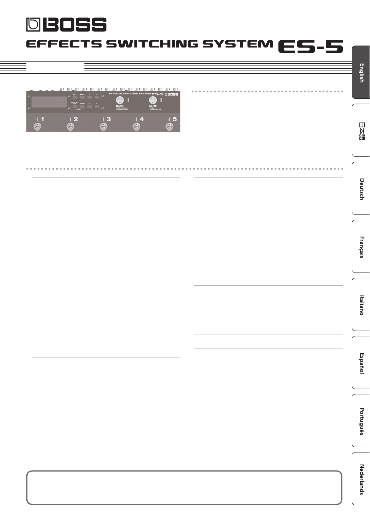
Main features
The ES-5 is a switching system that lets you connect eect pedals
and other eect units, and then store and recall up to 200 dierent
combinations of them.
It also provides a wide variety of external control functions for
controlling your amp and eects in real time.
Panel Descriptions . . . . . . . . . . . . . . . . . . . . . . . . . . . . . . . . . . . . . . . . 2
Rear Panel (Connecting Your Equipment) . . . . . . . . . . . . . . . . . . . 2
Top Panel . . . . . . . . . . . . . . . . . . . . . . . . . . . . . . . . . . . . . . . . . . . . . . . 4
Attaching the Rubber Feet . . . . . . . . . . . . . . . . . . . . . . . . . . . . . . . . 5
Turning the Power On and O . . . . . . . . . . . . . . . . . . . . . . . . . . . . 5
Switching the Play Screen . . . . . . . . . . . . . . . . . . . . . . . . . . . . . . . . 5
Saving/Recalling a Combination of Eect Units
(Memory Mode)
Patch Structure . . . . . . . . . . . . . . . . . . . . . . . . . . . . . . . . . . . . . . . . . . 6
Switching Between Memory and Manual Modes . . . . . . . . . . . . 6
Saving a Patch (Patch Write) . . . . . . . . . . . . . . . . . . . . . . . . . . . . . . 6
Recalling a Patch (Patch Change) . . . . . . . . . . . . . . . . . . . . . . . . . . 6
. . . . . . . . . . . . . . . . . . . . . . . . . . . . . . . . . . . . . . . . . . 6
Creating a Patch . . . . . . . . . . . . . . . . . . . . . . . . . . . . . . . . . . . . . . . . . . 7
Block Diagram . . . . . . . . . . . . . . . . . . . . . . . . . . . . . . . . . . . . . . . . . . 7
Tips for Creating Patches (Sounds) . . . . . . . . . . . . . . . . . . . . . . . . . 7
Changing the Eect Loop Settings . . . . . . . . . . . . . . . . . . . . . . . . . 8
Changing the Eect Loop Connection Order. . . . . . . . . . . 8
Making a Parallel Connection . . . . . . . . . . . . . . . . . . . . . . . . 8
Specifying Carryover . . . . . . . . . . . . . . . . . . . . . . . . . . . . . . . 8
Editing the Settings of a Patch (Memory Edit Mode) . . . . . . . . . 9
Basic Operation . . . . . . . . . . . . . . . . . . . . . . . . . . . . . . . . . . . . 9
Parameter List . . . . . . . . . . . . . . . . . . . . . . . . . . . . . . . . . . . . . 9
Advanced Applications . . . . . . . . . . . . . . . . . . . . . . . . . . . . . . . . . . . 15
Adjusting the Level of Each Patch . . . . . . . . . . . . . . . . . . . . . . . . . . 15
Switching the Amp’s Channels . . . . . . . . . . . . . . . . . . . . . . . . . . . . 15
Changing the BOSS DD-7’s Delay Time for Each Patch . . . . . . . . 16
Using the External Footswitch (BOSS FS-7’s B Switch) to Turn
Delay On/O . . . . . . . . . . . . . . . . . . . . . . . . . . . . . . . . . . . . . . . . . . . . 16
Using the External Footswitch (BOSS FS-7’s A Switch) to
Change the Delay Time . . . . . . . . . . . . . . . . . . . . . . . . . . . . . . . . . . . 17
Applying Phaser Only While the Currently Selected Number
Switch Is Held Down . . . . . . . . . . . . . . . . . . . . . . . . . . . . . . . . . . . . . 18
Switching a MIDI-Equipped Eect Unit’s Memory When a
Patch Is Changed . . . . . . . . . . . . . . . . . . . . . . . . . . . . . . . . . . . . . . . . 18
Using the Expression Pedal to Control a MIDI-Equipped Eect
Unit . . . . . . . . . . . . . . . . . . . . . . . . . . . . . . . . . . . . . . . . . . . . . . . . . . . . 19
Connecting a Wah or Fuzz (Input Buer O ) . . . . . . . . . . . . . . . . 19
Appendix . . . . . . . . . . . . . . . . . . . . . . . . . . . . . . . . . . . . . . . . . . . . . . . . . 20
Troubleshooting . . . . . . . . . . . . . . . . . . . . . . . . . . . . . . . . . . . . . . . . 20
Error Messages . . . . . . . . . . . . . . . . . . . . . . . . . . . . . . . . . . . . . . . . . . 20
Main Specications . . . . . . . . . . . . . . . . . . . . . . . . . . . . . . . . . . . . . . 21
USING THE UNIT SAFELY . . . . . . . . . . . . . . . . . . . . . . . . . . . . . . . . . . 21
IMPORTANT NOTES . . . . . . . . . . . . . . . . . . . . . . . . . . . . . . . . . . . . . . . 21
Making Global Settings (System Setting) . . . . . . . . . . . . . . . . . 12
List of Parameters . . . . . . . . . . . . . . . . . . . . . . . . . . . . . . . . . . . . . . . 12
Patch/Data Operations (Utility) . . . . . . . . . . . . . . . . . . . . . . . . . . . 13
Copying a Patch (Patch Copy) . . . . . . . . . . . . . . . . . . . . . . . . . . . . . 13
Exchanging Patches (Patch Exchange). . . . . . . . . . . . . . . . . . . . . . 13
Initializing a Patch (Patch Init) . . . . . . . . . . . . . . . . . . . . . . . . . . . . . 13
Copying a Bank (Bank Copy) . . . . . . . . . . . . . . . . . . . . . . . . . . . . . . 13
Exchanging Banks (Bank Exchange) . . . . . . . . . . . . . . . . . . . . . . . . 13
Copying a Group (Group Copy) . . . . . . . . . . . . . . . . . . . . . . . . . . . . 13
Exchanging Groups (Group Exchange) . . . . . . . . . . . . . . . . . . . . . 13
Transmitting Data to an External MIDI Device (Bulk Dump) . . . 13
Restoring the Factory Settings (Factory Reset) . . . . . . . . . . . . . . . 14
Before using this unit, carefully read “USING THE UNIT SAFELY” and “IMPORTANT NOTES” (leaet “USING THE UNIT SAFELY” and Owner’s Manual (p.
21)). After reading, keep the document(s) including those sections where it will be available for immediate reference.
Copyright © 2016 ROLAND CORPORATION
Page 2
Panel Descriptions
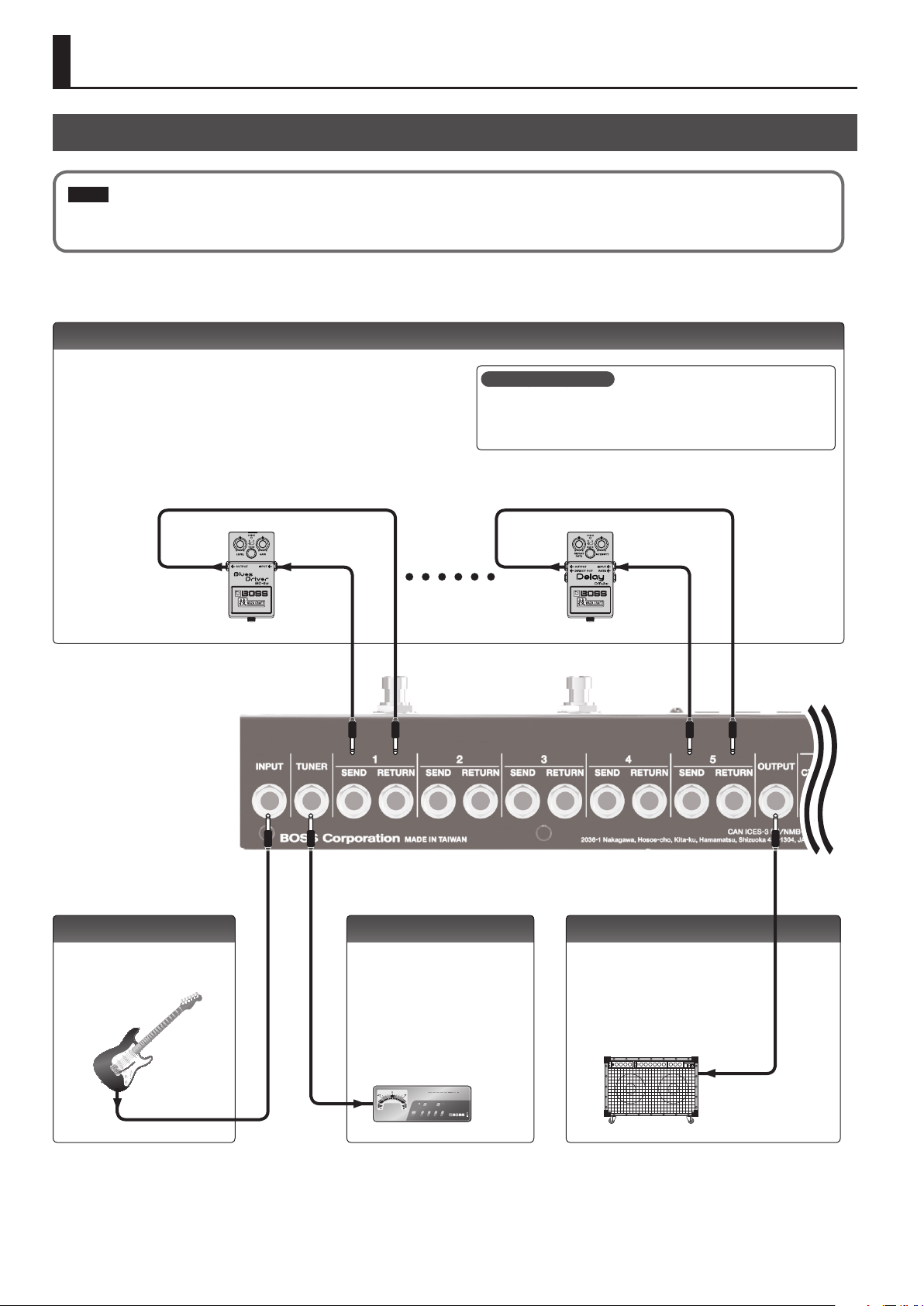
Rear Panel (Connecting Your Equipment)
NOTE
To prevent malfunction and equipment failure, always turn down the volume, and turn o all the units before making any connections.
SEND 1–5, RETURN 1–5 jacks
These jacks provide eect loops.
Signals are sent from SEND 1–5 jacks to each eect unit, and the signals from each
eect unit are received at the RETURN 1–5 jacks.
Connect the SEND 1–5 jacks to the INPUT jack of each eect unit, and connect the
OUTPUT jack of each eect unit to the RETURN 1–5 jacks.
SENDRETURN SENDRETURN
What is an eect loop?
This is a connection in which an eect device is connected via send and
return jacks. The ES-5 provides ve eect loops, 1–5.
INPUT jack
Connect your guitar or bass to this
jack.
2
TUNER jack
This jack is for connecting an external
tuner.
The signal that is input from the INPUT
jack is output from this jack even if
mute is on.
OUTPUT jack
This is the output jack.
Pressing the [MUTE] switch mutes the
output from the OUTPUT jack.
Page 3

Panel Descriptions
EXT CTL jacks
CTL 1/2, 3/4 jacks
These are control jacks for latch or
momentary operation.
You can use them to control various things
such as switching amp channels or turning
reverb on/o.
If you’re using an eect device that’s
equipped with a footswitch jack, connect
that jack here.
Each of these jacks can accommodate
a stereo 1/4” plug (TRS) to make the
appropriate connection to the device
you’re controlling.
* If 1/4” plug cables are connected, only
CTL 1 and CTL 3 are available.
TIP RING
RETURN
CTL 1
CTL 3
CTL 2
CTL 4
SEND
MIDI connectors
Connect an external MIDI device here to transmit and
receive MIDI messages.
The operation of the MIDI OUT/THRU connectors
depends on the system settings (p. 12).
MIDI device
DC IN jack
Connect the included AC
adaptor here.
The power turns on when
you plug the connected
AC adaptor into an AC
outlet.
CTL IN jack
These let you control eect units or amps that are connected to the EXT CTL
jacks.
To use this as EXP jack
Connect an expression pedal (such as the Roland
EV-5).
To use this as CTL 1/2 jack
Connect a footswitch.
FS-5U x 2
Mode/Polarity switch
FS-5U
FS-6
FS-7
Stereo 1/4” phone type
.
/
1/4” phone type
RINGTIP
CTL 1 CTL 2
NOTE
5 This instrument is equipped with balanced
5 Use only the specied expression pedal (FV-500H, FV-500L, Roland
FS-5U x 1
1/4” phone type
.
/
1/4” phone type
CTL 1
(TRS) type jacks. Wiring diagrams for these
jacks are shown below. Make connections
after rst checking the wiring diagrams of other equipment you intend
to connect.
EV-5; sold separately). By connecting any other expression pedals, you
risk causing malfunction and/or damage to the unit.
FS-6
Stereo 1/4” phone type
.
/
Stereo 1/4” phone type
CTL 2 CTL 1
FS-7
Stereo 1/4” phone type
.
/
Stereo 1/4” phone type
CTL 2
CTL 1
3
Page 4

Panel Descriptions
Top Panel
[EDIT] button
Press this to make patch settings or system
settings.
[DISPLAY/EXIT] button
Press this to switch the play screen, to cancel an
operation, or to return to the previous screen.
Lock function
When you press the [DISPLAY/EXIT] button and [ENTER] button simultaneously to activate
Lock function, all buttons will be disabled.
This prevents settings from being changed when you inadvertently press a button.
The Lock function turns o when you press the two buttons simultaneously once again.
Display
The ES-5 shows various information here.
[WRITE] button
Press this to save patch settings.
[ENTER] button
Press this to conrm an operation.
What is memory mode?
In this mode, you can select “patches,” where each patch is a combination of eect loops and various
settings.
You can select from 200 patches by using the buttons or switches to specify the group, bank, and
number.
What is manual mode?
In this mode you can turn the eect loops (1–5) on/o individually.
[–] [+] buttons
Use these to edit the value of a setting.
* Hold down one button while pressing the
other button to make the value change
rapidly.
[K] [J] buttons
Use these to move the cursor or to select a
category or parameter.
LOCKED!
Number switches [1]–[5]
Use these to select a patch number. The indicator of the
currently selected number is lit blue.
In manual mode, these switches turn each eect loop (1–5)
on/o individually. When an eect loop is on, its number
indicator is lit red.
MEMO
You can also assign a dierent function to each switch (p.
10).
4
[BANK] switch
In memory mode, use this switch to change banks. Each time you press the switch, you’ll cycle
through the banks in the order of 102030405010...
If you hold down this switch for two seconds or longer, you’ll switch between memory mode
(indicator lit blue) and manual mode (indicator lit red).
If you like, you can make this indicator blink in time with the tempo (p. 12).
* You can also change the way in which banks are switched (p. 12).
[MUTE] switch
Mutes the sound that is output from the ES-5. If mute is on, the indicator is lit blue.
Hold down the switch for two seconds or longer to enter the bypass state (indicator lit red); the
input is output without change.
Page 5
Panel Descriptions
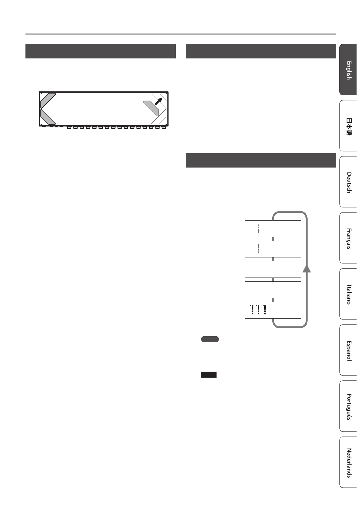
Attaching the Rubber Feet
You can attach the rubber feet (included) if necessary.
Attach the rubber feet in alignment with the marks on the bottom
of the unit.
* When turning the unit over, be careful so as to protect the buttons
and switches from damage. Also, handle the unit carefully; do not
drop it.
* If the rubber feet are not attached correctly, the unit may be
deformed when you press the switches.
Turning the Power On and O
Once everything is properly connected (p. 2), be sure to follow the
procedure below to turn on their power. If you turn on equipment in
the wrong order, you risk causing malfunction or equipment failure.
When powering up: Turn on the power to your guitar amp
When powering down: Turn o the power to your guitar amp
last.
rst.
Switching the Play Screen
The screen that appears when you turn on the power is called the
“play screen,” and the state in which the play screen is shown is
called “play mode.”
There are ve types of play screen as shown in the following
illustration, and you can use the [DISPLAY/EXIT] button to switch
between them.
111 BOSS ES-5
Patch name screen
Master BPM
Ì=120
&
Loop On/O screen
Loop structure screen
CTL out screen
Patch number screen
MEMO
Even in play mode, you can use the [K] [J] buttons and [–] [+]
buttons to edit the settings.
To save your edited settings, use the patch write (p. 6) operation.
NOTE
The explanations in this manual include illustrations that depict
what should typically be shown by the display. Note, however,
that your unit may incorporate a newer, enhanced version of the
system (e.g., includes newer sounds), so what you actually see in
the display may not always match what appears in the manual.
111 BOSS ES-5
5 * 3 * 1
_
O-5-4-3-2-1-I _
C1 |C2 |C3 |C4
ON|OFF| Ì |120 _
BOSS ES-5
_
Ì=120
5
Page 6
Saving/Recalling a Combination of Eect Units (Memory Mode)
“Memory mode” is the mode in which you can save combinations of eect loops (patches) in the ES-5, and recall those saved settings.
In contrast to memory mode, “manual mode” is the mode in which you can use the switches to turn each eect loop on/o manually.
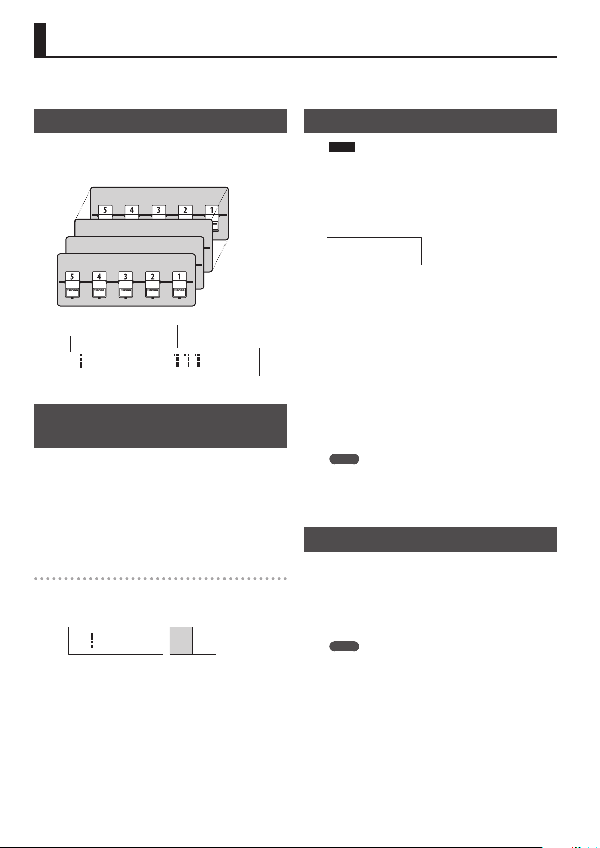
Patch Structure
A “patch” consists of a combination of eect loops (each eect loop’s
on/o status and connection order) and parameter settings.
Patches are organized by group (1–8), bank (1–5), and number (1–5).
You can store 200 patches.
Patch 855
Patch 113
Patch 112
Patch 111
Group
Bank
Number
111 BOSS ES-5
Ì=120
(Group/Bank/Number)
Group
Bank
Number
BOSS ES-5
Ì=120
Switching Between Memory and Manual Modes
Saving a Patch (Patch Write)
NOTE
5 The patch you created is lost if you turn o the power or switch
patches before performing the patch write operation.
5 When you perform the patch write operation, the patch that was
in the save-destination is lost.
1. Press the [WRITE] button.
111
Patch name
2. Use the [
save-destination group/bank/patch number.
* You can also use the [BANK] switch and number switches [1]–[5]
3. Press the [ENTER] button.
4. Use the [
patch name.
* If you decide to cancel the patch write operation, press the
5. Press the [WRITE] button or the [ENTER] button.
The display indicates “Executing...,” and then the previous display
reappears when patch write is completed.
K
] [J] buttons and [–] [+] buttons to select the
to select the bank number and patch number.
K
] [J] buttons and [–] [+] buttons to assign a
[DISPLAY/EXIT] button several times.
1. Hold down the [BANK] switch for two seconds or longer.
Each time you press this switch, you alternate between memory
mode and manual mode.
5 In memory mode, the BANK (MEMORY/MANUAL) indicator is lit
blue.
5 In manual mode, the BANK (MEMORY/MANUAL) indicator is lit
red.
In manual mode
Pressing the number switches [1]–[5] turns each eect loop on/o.
5 The number indicator is lit red if the corresponding eect loop is
on, and unlit if that eect loop is o.
111 BOSS ES-5
5 * 3 * 1
_
1, 3, 5 On
2, 4 O
MEMO
5 You can write a patch from either memory mode or manual
mode.
5 When you write a patch, the ES-5 switches to memory mode.
Recalling a Patch (Patch Change)
1. Use the [
group.
2. Use the [BANK] switch to select a bank.
3. Use the number switches [1]–[5] to select a patch.
K
] [J] buttons and [–] [+] buttons to select a
MEMO
5 In the patch name screen and patch number screen of Play
mode, you can use the [K] [J] buttons and [–] [+] buttons to
select a patch.
5 You can choose whether pressing the [BANK] switch cycles
through banks 1–5, or whether banks 1–5 are selected by
pressing the [BANK] switch and then pressing one of the number
switches [1]–[5].
For details on how to make this setting, refer to “Making Global
Settings (System Setting)” (p. 12).
5 You can specify whether the next patch is selected as soon as you
use the [BANK] switch to change banks, or whether the patch is
not changed until you then press a number switch.
For details on how to make this setting, refer to “Making Global
Settings (System Setting)” (p. 12).
6
Page 7
Creating a Patch
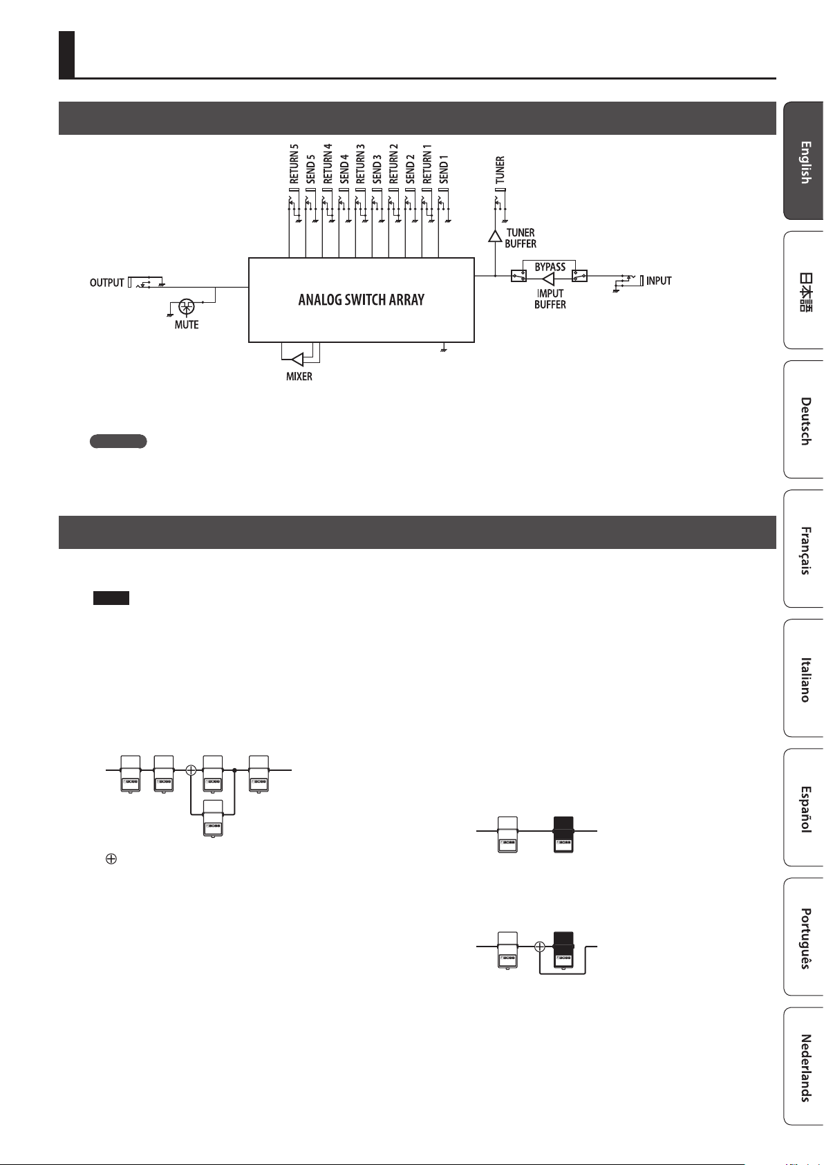
Block Diagram
The ES-5 uses an “analog switch array” that lets you freely change the connection order of your eect units.
It also contains an internal mixer, and lets you create a wide range of sounds by connecting eect units in parallel or using the “Carryover” function.
Carryover
This function cuts only the input while leaving the output connected when you change patches. For example, you can use this to allow just the
delay sound to remain when switching patches.
Tips for Creating Patches (Sounds)
Using the internal mixer is important in order to take advantage of the ES-5’s unique features, such as the ability to connect loops in parallel and use
the Carryover function. Understanding how to use the mixer will make it even more enjoyable to create patches (sounds).
NOTE
5 The same mixer is used for parallel connections and for Carryover. This means that depending on the settings, you might not be able to use a
parallel connection, or that Carryover might not work.
5 If you connect a loop in parallel or if you use the Carryover function, the mixer is congured appropriately for the parallel connections or Carryover
settings.
If you turn on the mixer without specifying parallel connections or Carryover, the mixer is congured immediately before the output.
Parallel connection
: Mixer
Using the Carryover function
This lets you preserve the sound (e.g., delay sound) when you switch
patches.
5 Before the patch change
Delay
5 After the patch change
The send to the delay loop is cut, and only the return is mixed
with the direct sound.
’
Delay sound
Delay
’
Direct sound
* To use the Carryover function, enable Carryover for the patch that
follows the patch change.
* Carryover might not work if the Loop Structure (p. 9) settings
dier before and after the patch change.
7
Page 8

Creating a Patch
Changing the Eect Loop Settings
In the Loop Structure screen you can make the following settings.
5 Change the connection order of the eect loops
5 Create a parallel connection
5 Specify Carryover
Loop Structure screen
The Loop Structure screen shows the following content.
O- -4-3-2-1-I _
I
INPUT
1– 5
Loop number
A loop for which Carryover is specied
–
O
OUTPUT
Changing the Eect Loop Connection Order
Before the change
Making a Parallel Connection
Example: Connect eect loops 2 and 3 in parallel
4. Use the [
point of the parallel connection, and press the [ENTER]
button.
Move the cursor between eect loops 2 and 4, and press the [ENTER]
button; the parallel loop is created.
* Depending on the settings, there might be cases in which parallel
5. Use the [
you want to change.
Move the cursor to eect loop 3.
6. Use the [–] button to move the loop number.
When you press the [–] button three times to move eect loop 3,
eect loops 2 and 3 are connected in parallel.
K
] [J] buttons to move the cursor to the merge
O-5-4-2-3-1-I
_
-
connection is not possible (p. 7).
J
] button to select the loop whose connection
O-5-4-2-3-1-I
_
-
Split pointMerge point
INPUTOUTPUT
Example: Change the order of eect loops 2 and 3
1. In play mode, press the [DISPLAY/EXIT] button several
times to access the Loop Structure screen.
O-5-4-3-2-1-I _
2. Use the [
connection you want to change.
Move the cursor to eect loop 2.
K
] [J] buttons to select the loop whose
O-5-4-3-2-1-I _
3. Use the [–] [+] buttons to move the loop number.
When you press the [–] button, eect loops 2 and 3 change places.
O-5-4-2-3-1-I _
O-5-4-2-1-I
3
_
Cancelling a Parallel Connection
Use the [K] [J] buttons to move the cursor to the merge point of
the parallel connection, and press the [ENTER] button; the parallel
connection is cancelled.
_
3
O-5-4-3-2-1-I _ O-5-4-2-1-I
Specifying Carryover
Example: You can specify Carryover for eect loop 5
O- -4-3-2-1-I _
K
] [J] buttons to select the loop for which you
7. Use the [
want to specify Carryover, and press the [ENTER] button.
Move the cursor to eect loop 5 and press the [ENTER] button;
Carryover is specied.
* Depending on the settings, there are cases in which Carryover
does not work (p. 7).
8
Page 9

Creating a Patch
Editing the Settings of a Patch (Memory Edit Mode)
MEMO
Once you’re in memory edit mode, you won’t be able to switch
between memory mode and manual mode.
Also, the number switches [1]–[5] will turn each eect loop on/
o.
Basic Operation
1. Recall the patch that you want to edit.
2. Press the [EDIT] button.
3. Use the [
press the [ENTER] button.
(Example)
4. Use the [
the [ENTER] button.
(Example)
5. Use the [
[+] buttons to specify its value.
6. To save the edited settings, write the patch.
To cancel without saving, press the [DISPLAY/EXIT] button several
times.
K
] [J] buttons to select “Patch” or “CTL/EXP,” and
Loop On/Off
[ENTER]
K
] [J] buttons to select a parameter, and press
Input Buffer
ON _
K
] [J] buttons to move the cursor, and use the [–]
Parameter List
Patch
Parameter Value/Explanation
Patch Name Up to 12 characters
You can turn each eect loop on/o. When on, a “
* You can also turn them on/o by pressing the number
Loop On/O
Loop Structure
Carryover
C1–4
Input Buer
Mixer Sw
Mixer Gain
Master BPM
switches [1]–[5].
5 4 3 2 1
You can make the following settings. For details on operation,
refer to “Changing the Eect Loop Settings” (p. 8).
5 Connection order of each eect loop
5 Parallel connection settings
5 Carryover setting
* Depending on the settings, there are cases in which parallel
connection is not possible, or in which Carryover does not
work.
O-5-4-2-1-I
3
_
Specify the control signals that are sent from the EXT CTL CTL 1/2,
3/4 jacks when you switch patches.
The available control signals depend on the Play Option/C1–4
setting (p. 12).
For LAT
OFF Sends “o”
ON Sends “on”
For PLS, INV
OFF
ON
For TP2–4
OFF Sends nothing
ª–˜
20–500
Turns the input buer on/o.
ON, OFF
Turns the mixer on/o.
If you connect a loop in parallel or use the Carryover function, the
mixer turns on automatically.
ON, OFF
This is the output gain of the mixer. It is available only if Mixer Sw
is ON.
* If Mixer Sw is ON, the signal is output through the ES-5’s op-
amp.
* If Input Buer is o and all eect loops are o, turning Mixer
Sw on might lower the volume.
-12 dB, -9 dB, -6 dB, -3 dB, 0 dB, +3 dB, +6 dB
Species the patch’s BPM.
20–500
” icon is shown.
Sends a short (100 ms) pulse when changing
between “o” and “on.”
* If the display of the ES-5 diers from the
state of the connected equipment, switch
the state of the connected equipment.
Sends tempo at the interval of the specied
note value according to the Master BPM value
* Depending on the Master BPM setting,
there are cases in which this cannot be
sent.
Sends the specied tempo (¸=)
9
Page 10

Creating a Patch
Parameter Value/Explanation
Patch MIDI 1–8
* When the Patch MIDI screen is displayed, pressing the [ENTER] button transmits all
of the MIDI messages that are assigned in Patch MIDI 1–8.
Ch
LSB
MSB
PC
Ctl1–2 CC#
Ctl1–2 Val
Species the transmit channel for MIDI messages.
OFF (not transmitted), 1–16
Species whether bank select messages are transmitted when
you switch patches.
* It is not possible to turn on only Bank LSB.
* Not transmitted if PC is OFF.
* It is not possible to transmit only bank select. Bank select is
always transmitted in conjunction with program change.
OFF Not transmitted.
0–127 The specied value is transmitted.
Species whether a program change is transmitted when you
switch patches.
OFF Not transmitted.
1–128 The specied value is transmitted.
Species whether a control change is transmitted when you
switch patches.
OFF Not transmitted.
CC#000–127 The specied control change is transmitted.
Species the value of the control change.
0–127
CTL/EXP
Parameter Value/Explanation
BANK, MUTE, NUMBER 1–5, CTL IN 1–2
* If the Preference (p. 12) parameter is set to SYS, the screen indicates (SYS).
Func
Min, Max
Mod
Specify the function of the [BANK] switch, [MUTE] switch, number
switches [1]–[5], and footswitches connected to the CTL IN jack.
* If Patch Slct Mod (p. 12) is set to MODE 2, BnkM/BnkD/BnkU
wait for the bank to be selected.
OFF Pressing the switch does nothing.
MemM
Mute [MUTE] switch
BnkM
GrpD, GrpU
BnkD, BnkU
MemD, MemU
Num1–5 Number switches [1]–[5]
Ctl1–4
BPM Tap the switch to control the master BPM.
Specify the values that are sent when the switch is pressed (Max)
and released (Min).
* These settings are available only when Func is Ctl1–4.
OFF Sends “o”
ON Sends “on”
Species the operation of the switch.
* These settings are available only when Func is Ctl1–4.
MOM
TGL
Switches between memory mode and manual
mode.
Change banks
5 10203040501...
5 Hold down for two seconds to switch
between memory/manual modes
Change groups
5 GrpD: 807060...108...
5 GrpU: 102030...801...
Change banks
5 BnkD: 50403020105...
5 BnkU: 10203040501...
Change patches
5 MemD: 8550111
5 MemU: 1110855
A control signal is sent from the
corresponding EXT CTL jack CTL 1/2, 3/4.
Normally o; on only while the switch is being
operated.
Alternates on/o each time the switch is
operated.
Parameter Value/Explanation
EXP IN
* If the Preference (p. 12) parameter is set to SYS, the screen indicates (SYS).
Func
Min, Max
Assign (A) 1–8
Sw
Src
Mod
Cate Selects the Target category.
Target Species the parameter to be controlled.
Min
Max
*1
Ch
*1
CC#
Act L
Act H
*2
Trig
*2
Tim
Specify the function of the expression pedal connected to the
CTL IN jack.
OFF Operating the pedal does nothing.
BPM Use the pedal to control Master BPM.
Specify the values that are sent when the pedal is advanced (Max)
and returned (Min).
* This can be set only if Func is BPM.
(Min) 20–500, (Max) 20–500
Turns the assignment on/o.
ON, OFF
Species the controller (source).
CTL1, 2 A footswitch connected to a CTL IN jack
Mute [MUTE] switch
Bank [Bank] switch
Num1–5 Number switches [1]–[5]
CNum Currently selected number switch
EXP
INT
WAV
CC000–127
Species the operation of the controller.
MOM
TGL
Species the range of change for the
parameter. The values will depend on
the parameter that’s assigned by Target.
Species the transmit channel for control changes.
1–16
Species the controller number that is transmitted.
000–127
Within the operating range of the source, this species the range
that will control the target parameter.
(L) 0–126
(H) 1–127
Species how the motion of the internal pedal will be triggered.
PAT When the patch is switched
ExpL, ExpM, ExpH
CTL1, 2 A footswitch connected to a CTL IN jack
Mute [MUTE] switch
Bank [BANK] switch
Num1–5 Number switches [1]–[5]
CNum Currently selected number switch
CC000–127
Species the time over which the internal pedal will move from
the released (heel) position to the depressed (toe) position.
0–100
An expression pedal connected to a CTL IN
jack.
Internal pedal
The virtual expression pedal
will begin operating when
started by the specied trigger
(Trig), modifying the parameter
specied by “ Target.”
Wave pedal
The virtual expression pedal will cyclically
modify the parameter specied by “Target” in
a xed wave form.
Control change number from an external MIDI
device
The value will normally be o (minimum
value), and will be on (maximum value) only
while the control is being operated.
The value will toggle between o (minimum)
and on (maximum) each time the control is
operated.
For details, refer to
“Target List” (p. 11).
The target parameter will be controlled within
the range specied. Normally, you should
leave Act L at “0” and Act H at “127.”
When an expression pedal connected to a CTL
IN jack (EXP) enters the following status
ExpL Minimum
Advance the pedal through the
ExpM
central value
ExpH Maximum
When the specied controller number is
received
10
Page 11

Parameter Value/Explanation
Select one of the following curves to specify the change
produced by the internal pedal.
*2
Crv
Species the time for one cycle of the wave pedal.
*3
Rate
Form
*3
*1 Shown if Cate is set to MIDI.
*2 Shown if Src is set to INT.
*3 Shown if Src is set to WAV.
ª–˜
, 0–100
Select one of the following to specify the change produced by
the wave pedal.
Target List
Target Min/Max Explanation
When Cate is set to LOOP
L1–5
When Cate is set to E.CTL
CTL1–4
When Cate is set to MODE
MemM
Mute
Byps
When Cate is set to MIDI
000–127
When Cate is set to BPM
MstBPM
Tap
When Cate is set to LED
Mute, Bank,
Num1–5
OFF, ON
OFF, ON
OFF, ON
OFF, ON
MEM, MAN
MEM, MAN
OFF, ON
OFF, ON
OFF, ON
OFF, ON
0–127
0–127
20–500
20–500
OFF, ON
OFF, ON
OFF, ON
OFF, ON
Eect loop on/o
Switches the setting of the jack.
Switches between memory mode and manual mode.
Mute on/o
Bypass on/o
The control change value is transmitted from the MIDI
OUT connector.
Master BPM
Uses tap operations to set the Master BPM.
Lights or turns o the indicator of the controller that is
set to Target.
Creating a Patch
If this is set to a note value, a time
corresponding to the “Master BPM” value
specied for each patch is assigned.
11
Page 12

Making Global Settings (System Setting)
Settings that are shared by the entire ES-5 are called “system settings.”
1. Press the [EDIT] button.
2. Use the [
category (Play Option–Others), and then press the [ENTER]
button.
K
] [J] buttons to select the system setting
Play Option
[ENTER]
Switch Mode
PUSH
List of Parameters
Parameter Value/Explanation
Category: Play Option
Switch Mode
Bank Chg Mode
C1–4
Bank Extent Min,
Max
Patch Chg Time
Patch Slct Mod
Beat Indicator
Species the timing at which the bank or patch is changed when
you operate the switch.
PUSH
RELEASE
Species how patches are switched.
* Regardless of the Bank Chg Mode setting, the group is
switched immediately.
WAIT
IMMEDIATE
Species the operation of the EXT CTL CTL 1/2, 3/4 jacks.
LAT (Latch) Latch operation
PLS
INV
TP2 (Tap 2)
TP3 (Tap 3)
TP4 (Tap 4)
Specify the lower and upper limit of the banks that can be
selected. Only the specied range of banks are available for
selection.
(Min) 1–5, (Max) 1–5
Species the mute time when switching patches.
0–10
Species how patches are switched.
MODE1
MODE2
If this is ON, the BANK (MEMORY/MANUAL) indicator blinks in
time with the Master BPM (p. 9) setting.
OFF, ON
The change happens when you press the
switch.
The change happens when you release the
switch.
Although the indication in the display is
updated to reect the change in the bank
when a [BANK] switch is pressed, the patch will
not change until a number switch has been
pressed.
The patch switches instantly when a [BANK]
switch or any of the number switch is pressed.
Send a pulse when changing patches
PLS
Patch change Patch change
INV
Patch change Patch change
Turns on/o twice at the Master BPM setting
when the patch changes
Turns on/o three times at the Master BPM
setting when the patch changes
Turns on/o four times at the Master BPM
setting when the patch changes
Each time the [BANK] switch is pressed, cycle
through 102030405010…
Press the [BANK] switch and then press a
number switch [1]–[5] to switch to banks 1–5.
3. Use the [
K
] [J] buttons to select a parameter, and then
press the [ENTER] button.
Switch Mode
PUSH _
4. Use the [–] [+] buttons to specify the value.
5. Press the [DISPLAY/EXIT] button several times to return to
the play screen.
Parameter Value/Explanation
Category: Preference
Input Buer
BANK, MUTE,
NUMBER 1–5,
CTL IN 1–2,
EXP IN
Category: MIDI Setting
MIDI Out Mode
Rx Ch
Dev ID
Sync
Clock Out
Category: PC Map
Bank 0/PC# 1/
Memory
|
Bank 1/PC#128/
Memory
Category: Others
LCD Contrast
Pol Exp
Pol C1, C2
Species whether the input buer uses the setting of each patch
or the system setting.
PAT The settings of each patch are used.
OFF, ON Turns the input buer on/o.
Specify whether the functions of the [BANK] switch, [MUTE]
switch, number switches [1]–[5], and CTL IN jack use the settings
of each patch or the system setting.
PAT The settings of each patch are used.
SYS The settings of system settings are used.
Selects the operation of the MIDI OUT/THRU connector.
OUT Operates as a MIDI OUT connector.
THRU
Species the MIDI channel on which MIDI messages are received.
1–16
Species the device ID used to transmit and receive exclusive
messages.
1–32
This setting determines the basis used for synchronizing the
timing for tempo and other time-based parameters.
* When synchronizing performances to the MIDI Clock signal
from an external MIDI device, timing problems in the
performance may occur due to errors in the MIDI Clock.
INT Synchronize with the ES-5’s internal clock.
AUTO
Species whether MIDI clock messages are transmitted.
ON, OFF
You can use the “program change table” to freely specify the
correspondence between program change messages received by
the ES-5 and the patches that are selected.
111–855
Adjust the contrast (brightness) of the display.
1–10
Specify the polarity of the CTL IN EXP jack.
ST
IN
Specify the polarity of the CTL IN CTL 1/2 jack.
ST If a BOSS footswitch is connected
IN
Operates as a MIDI THRU connector.
MIDI data received at MIDI IN is mixed with the
MIDI data of the ES-5, and output together.
Synchronize with MIDI clock received via MIDI.
However, automatically synchronize with the
ES-5’s internal clock if MIDI clock messages
cannot be received.
Specify the group/bank/number of the patch
that is selected when “bank select MSB +
program number” are received.
* Bank select LSB is ignored.
If a Roland or BOSS expression pedal is
connected
If pressing or releasing the connected
expression pedal produces the opposite result
from what is expected
If pressing or releasing the connected
footswitch produces the opposite result from
what is expected
12
Page 13

Patch/Data Operations (Utility)
1. Press the [EDIT] button.
2. Use the [
3. Use the [
K
] [J] buttons to select “Utility” and press the [ENTER] button.
K
] [J] buttons to select the desired item, and press the [ENTER] button.
Copying a Patch (Patch Copy)
Patch Copy
111 Ã 855 _
Select the copy-source and copy-destination patches, and press the [ENTER] button.
* The copy-destination patch is overwritten.
Exchanging Patches (Patch Exchange)
Patch Exchange
111 ÅÃ 855 _
Select the exchange-source and exchange-destination patches, and press the [ENTER] button.
Initializing a Patch (Patch Init)
Patch Init
111 _
Select a patch that you want to initialize, and press the [ENTER] button.
When the conrmation message appears, press the [ENTER] button once again.
Copying a Bank (Bank Copy)
Bank Copy
11 Ã 85 _
Select the copy-source and copy-destination bank, and press the [ENTER] button.
* All patches in the copy-destination bank are overwritten.
Exchanging Banks (Bank Exchange)
Bank Exchange
11 ÅÃ 85 _
Select the exchange-source and exchange-destination banks, and press the [ENTER] button.
Copying a Group (Group Copy)
Group Copy
1 Ã 8 _
Select the copy-source and copy-destination group, and press the [ENTER] button.
* All patches in the copy-destination group are overwritten.
Exchanging Groups (Group Exchange)
Group Exchange
1 ÅÃ 8 _
Select the exchange-source and exchange-destination groups, and press the [ENTER] button.
Transmitting Data to an External MIDI Device (Bulk Dump)
Bulk Dump
Frm:Sys To:855 _
Frm (From)
To
*1
Sys, 111–855
111–855, Sys (*1)
Shown if Frm is set to Sys.
With the ES-5, you can use Exclusive messages to set another ES-5 to the same settings or to save settings to MIDI sequencers and
other such devices. This transmission of data is referred to as bulk dump.
“System settings” + “settings of the selected patch” can be transmitted.
When Transmitting Data to Another ES-5
Make connections as shown in the illustration below, and set the
transmitting and receiving units to the same device ID (p. 12).
INOUT
When Saving to a MIDI Sequencer
Connect as shown in the gure below, and put the sequencer in
the state where it is ready to receive Exclusive messages.
INOUT
MIDI sequencer
Transmitting unit Receiving unit
Specify the highest patch whose data you want to transmit, and press the [ENTER] button.
Restoring saved data from a MIDI sequencer to the ES-5
Connect your MIDI sequencer’s MIDI OUT to the ES-5’s MIDI IN, select the same device ID as when transmitting the data to the MIDI
sequencer, and then transmit the data from the MIDI sequencer.
13
Page 14

Patch/Data Operations (Utility)
Restoring the Factory Settings (Factory Reset)
Factory Reset
Frm:Sys To:855 _
“System settings” + “settings of the selected patch” can be returned to their factory-set condition (Factory Reset).
* All data that is reset is lost.
Frm (From)
To
*1
Sys, 111–855
111–855, Sys (*1)
Shown if Frm is set to Sys.
Specify the highest patch that you want to reset, and press the [ENTER] button.
When the conrmation message appears, press the [ENTER] button once again.
14
Page 15

Advanced Applications
Adjusting the Level of Each Patch
Parameter Value Reference
Patch parameter
Mixer Sw ON
Mixer Gain -12 dB, -9 dB, -6 dB, -3 dB, 0 dB, +3 dB, +6 dB
AMP
Guitar AMP
OUTPUT
COMP OD PHASER DELAYDIST
Mixer
DELAY PHASER DIST OD COMP
p. 9
NOTE
5 If you’re not using a parallel loop connection or Carryover, the mixer is
placed immediately before the output.
5 If Input Buer is o and all eect loops are o, turning Mixer Sw on
might lower the volume.
Input
Buer
Guitar
INPUT
Switching the Amp’s Channels
Parameter Value Reference
Patch parameter
C1–4 ON, OFF p. 9
System setting
Play Option: C1–4 LAT, PLS p. 12
AMP
Guitar AMP
OUTPUT
Channel switching jack
Mixer
DELAY PHASER DIST OD COMP
* As appropriate for the amp you’re using, set Play Option: C1–4 to
“LAT” or “PLS.”
Input
Buer
Guitar
INPUT
COMP OD
DIST
PHASER DELAY
15
Page 16

Advanced Applications
Changing the BOSS DD-7’s Delay Time for Each Patch
Parameter Value Reference
Patch parameter
C1–4
System setting
Play Option: CTL1–4 TP2–TP4 p. 12
AMP
Guitar AMP
OUTPUT
COMP OD PHASER DD-7DIST
Mixer
ª–˜
, 20–500
DD-7
p. 9
PHASER DIST OD COMP
EXP/CTL
The tap signal sent by the ES-5 changes the delay time
* If you connect to the BOSS PH-3’s EXP/CTL jack, you can change
the Rate.
* Depending on the settings of C1–4, there might be cases in which
the delay time cannot follow.
Input
Buer
Guitar
INPUT
Using the External Footswitch (BOSS FS-7’s B Switch) to Turn Delay On/O
Parameter Value Reference
Patch parameter (CTL/EXP)
CTL IN 1 Func OFF
Assign 1
Guitar AMP
Sw ON
Src CTL1
Mod TGL
Cate, Target LOOP, L5
Min, Max OFF, ON
Act L, Act H 0, 127
AMP
OUTPUT
Mixer
p. 10
DELAY PHASER DIST OD COMP
FS-7 B switch: Delay On/O
* You can also add an assignment to make the indicator light (p. 11).
Input
Buer
INPUT
Guitar
16
Mono or TRS cable
COMP OD PHASER DELAYDIST
FS-7
Page 17

Advanced Applications
Using the External Footswitch (BOSS FS-7’s A Switch) to Change the Delay Time
Parameter Value Reference
Patch parameter (CTL/EXP)
CTL IN 2 Func OFF
Assign 1
System setting
Play Option: C1 TP2–TP4 p. 12
Sw ON
Src CTL2
Mod MOM
Cate, Target E.CTL, CTL1
Min, Max OFF, ON
Act L, Act H 0, 127
p. 10
A delay unit that supports tap tempo
AMP
Guitar AMP
COMP
OUTPUT
OD
Mixer
(e.g., BOSS DD-7)
DD-7
PHASER
PHASER
EXP/CTL
DIST OD COMP
FS-7 A switch: Tap Tempo
DD-7DIST
Mono or TRS cable
TRS cable
FS-7
Input
Buer
Guitar
INPUT
17
Page 18

Advanced Applications
Applying Phaser Only While the Currently Selected Number Switch Is Held Down
Parameter Value Reference
Patch parameter (CTL/EXP)
Assign 1
Sw ON
Src CNum
Mod MOM
Cate, Target LOOP, L4
Min, Max OFF, ON
Act L, Act H 0, 127
p. 10
Input
Buer
INPUT
Guitar
AMP
COMP
OUTPUT
Mixer
OD PHASER DELAYDIST
DELAY PHASER DIST OD COMP
Phaser On Phaser O
AMP
Switching a MIDI-Equipped Eect Unit’s Memory When a Patch Is Changed
Parameter Value Reference
Patch Parameter
Patch MIDI 1
Ch 1–16
LSB OFF, 0–127
MSB OFF, 0–127
PC 1–128
p. 10
* Set Ch (MIDI channel) to match the MIDI device that’s connected.
* If you want to switch more than 128 memories, use LSB and MSB
(bank select LSB, MSB) as well.
* The MIDI specication counts the PC (program change) starting
at 1, but some devices start at 0. In this case, the memory number
that is one less than the ES-5’s PC setting is selected.
Guitar
18
Guitar
AMP
OUTPUT
COMP OD PHASERDIST
MIDI-equipped eect unit
(e.g., BOSS DD-500)
Mixer
BOSS
DD-500
MIDI IN
PHASER DIST OD COMP
MIDI cable
AMP
DD-500
Input
Buer
Guitar
INPUT
Page 19

Using the Expression Pedal to Control a MIDI-Equipped Eect Unit
Advanced Applications
Parameter Value Reference
Patch parameter (CTL/EXP)
Assign 1
Guitar
Sw ON
Src EXP
Mod –
Cate MIDI
Ch 1–16
CC# 000–127
Min, Max 0, 127
Act L, Act H 0, 127
AMP
OUTPUT
Mixer
MIDI-equipped eect unit
(e.g., BOSS DD-500)
BOSS
DD-500
MIDI IN
PHASER
p. 10
DIST OD COMP
MIDI cable
AMP
* Set Ch (MIDI channel) and CC# (controller number) to match the
MIDI device that’s connected.
* By making multiple assignments, you can control multiple
parameters simultaneously.
Input
Buer
Guitar
INPUT
COMP
OD
DIST
PHASER
DD-500
Connecting a Wah or Fuzz (Input Buer O)
The sound of some wah or fuzz units may change if they are
connected after a buer.
In this case, turn the ES-5’s input buer (Input Buer) o.
DELAY PHASER DIST OD WAH
AMP
Guitar
AMP
OUTPUT
Mixer
Expression Pedal
Parameter Value Reference
Patch parameter
Input Buer OFF p. 9
Guitar
INPUT
(FUZZ)
Input
Buer
WAH OD PHASER DELAYDIST
(FUZZ)
19
Page 20

Appendix
Troubleshooting
Problem Items to check Action
No sound / volume too low
Oscillating sound occurs
Sound switches on its own
Patch does not change
Sound does not change when you
switch patches
Can’t change the settings of a
connected eect unit
Can’t specify Carryover / Can’t
specify parallel connection
Can’t use a controller to modify a
parameter
MIDI messages are not
transmitted/received
Eect not applied Could the eect switch be o? Check the on/o setting of each eect. –
Are the connection cables broken? Try using a dierent set of connection cables. –
Is the ES-5 correctly connected to the other devices? Check connections with the other devices. p. 2
Is the connected amp turned o, or the volume
lowered?
Could the volume pedal have lowered the level? Advance the volume pedal. –
Could mute be turned on? Press the [MUTE] switch to turn mute o. p. 4
Is each eects set correctly? Check the settings of each eects. –
Is the power to the external device connected to the
SEND 1–5 and RETURN 1–5 jacks o, or is the volume of
the device turned down?
Could you be using a connection cable that contains
a resistor?
Could you have turned Input Buer o and connected
an eect loop in parallel, or specied Carryover?
Could the gain value or the value of a volume-related
parameter be too high due to the settings of a
connected amp or eect unit?
Could an external MIDI device be set to modify the
parameters?
Is “INT” or “WAV” set as the Src in Assign?
Is something other than the Play screen shown in the
display?
Could you have changed the function of the [BANK]
switch or the number switches [1]–[5]?
Are the loop settings of each patch correct? Check the loop settings. p. 9
Is the EXT CTL jack connected?
Is the cable the correct type (mono, TRS)?
Could you already be using the mixer?
Could the loop be turned o? Turn the loop on. p. 6
Is the Preference setting set to anything other than
PAT?
Do the MIDI channel settings of both devices match? Make sure that the MIDI channels of both devices match.
Do the controller number settings of both devices
match?
Are the MIDI cables broken? Try another set of MIDI cables. –
Are the MIDI cables connected correctly? Connect MIDI IN and MIDI OUT. –
Do the MIDI channel settings match?
Check the settings of your amp/mixer system. –
Check the settings for the connected device. –
Use a connection cable that does not contain a resistor. –
Depending on the impedance of the signal, the volume may
diminish. Turn on Input Buer.
Lower these values. –
Check the assignment settings.
When the Src is set to “INT” or “WAV,” the eect parameter set as
the Assign Target changes automatically.
On the ES-5, patches can be selected only when the Play screen is
displayed. Press the [DISPLAY/EXIT] button several times to return
to the Play screen.
If the Func setting is set to OFF, change it to Bank, or Num1–5. p. 10
Check the cable type and connection. p. 3
There is only one internal mixer.
Turn o the mixer that you’re already using.
To change the settings for an individual patch, set the Preference
setting to PAT. To change a specic setting for all patches in
common, select a setting other than PAT.
Make sure that the controller number of both devices match.
Match the MIDI channel settings.
Receive channel of the ES-5: MIDI Setting 0 Rx Ch
Transmit channel of the ES-5: Patch MIDI 1–8 0 Ch
p. 9
p. 10
p. 5
p. 7
p. 9
p. 12
p. 10
p. 12
p. 12
p. 10
Error Messages
Display Problem Action
MIDI BUFFER FULL!
MIDI OFFLINE!
DATA WRITE ERROR! Writing to the memory for storage of user data failed.
LOCKED! The buttons are locked. Turn “Lock function” o. p. 4
NO MORE MIXER IS AVAILABLE! The internal mixer is already being used. Check the Loop Structure settings. p. 7, p. 9
SYSTEM ERROR! A problem has occurred in the system. Contact your dealer or a nearby Roland service center. –
MEMORY DAMAGED!
The data cannot be processed correctly due to the high
volume of MIDI messages.
Transmissions from the connected device have been
interrupted. This message also appears when the
power to the connected device has been turned o. It
does not indicate damage.
It is possible that the contents of memory have been
damaged.
20
Reduce the volume of MIDI messages transmitted to the ES-5.
Reduce the tempo of the transmitting MIDI device.
Check to make sure no cable is disconnected and that there are
no shorts.
The unit may be damaged. Consult the nearest Roland service
center.
Please execute a Factory Reset. If this does not resolve the
problem, contact your dealer or a nearby Roland service center.
–
–
–
–
Page 21

Main Specications
BOSS ES-5: Eects Switching System
Modes Memory mode/Manual mode
Loops 5
Patch Memory 200
Nominal Input Level INPUT, RETURN 1–5: -10 dBu
Maximum Input Level INPUT, RETURN 1–5: +13 dBu
Input Impedance INPUT: 1 MΩ (Buer: On)
Nominal Output Level SEND 1–5, OUTPUT, TUNER: -10 dBu
Maximum Output Level SEND 1–5, OUTPUT, TUNER: +13 dBu
Output Impedance OUTPUT, TUNER: 1 kΩ (Mixer: On)
Recommended Load Impedance 10 kΩ or greater
Controls
Display 16 characters, 2 lines (backlit LCD)
Indicator Number 1–5 indicator, BANK (MEMORY/MANUAL) indicator, MUTE indicator
Connectors
Power Supply AC adaptor
Current Draw 125 mA
Dimensions
Weight 1.3 kg / 2 lbs 14 oz
Accessories AC adaptor, Owner’s manual, Leaet “USING THE UNIT SAFELY,” Rubber foot x 4
Options (sold separately)
* 0 dBu= 0.775 Vrms
Number 1–5 switches, BANK switch, MUTE switch, EDIT button, WRITE button, – button, + button, DISPLAY/EXIT button,
ENTER button, K button, J button
INPUT jack, SEND 1–5 jacks, RETURN 1–5 jacks, OUTPUT jack, TUNER jack: 1/4-inch phone type
EXT CTL CTL 1/2, CTL 3/4 jacks, CTL IN EXP CTL 1/2 jack: 1/4-inch TRS phone type
MIDI connectors (IN, OUT/THRU)
DC IN jack
337 (W) x 97 (D) x 68 (H) mm
13-5/16 (W) x 3-7/8 (D) x 2-11/16 (H) inches
Footswitch: FS-5U, FS-5L, FS-6, FS-7
Expression pedal: FV-500L, FV-500H, Roland EV-5
USING THE UNIT SAFELY
USING THE UNIT SAFELY
WARNING
To completely turn o power to the unit, pull out the plug
from the outlet
When the power needs to be completely turned o, pull
out the plug from the outlet. For this reason, the outlet
into which you choose to connect the power cord’s
plug should be one that is within easy reach and readily
accessible.
Use only the supplied AC adaptor and the correct voltage
Be sure to use only the AC adaptor supplied with the
unit. Also, make sure the line voltage at the installation
matches the input voltage specied on the AC adaptor’s
body. Other AC adaptors may use a dierent polarity, or
be designed for a dierent voltage, so their use could result in
damage, malfunction, or electric shock.
IMPORTANT NOTES
Repairs and Data
• Before sending the unit away for repairs, be sure to make
a backup of the data stored within it; or you may prefer to
write down the needed information. Although we will do our
utmost to preserve the data stored in your unit when we carry
out repairs, in some cases, such as when the memory section
is physically damaged, restoration of the stored content may
be impossible. Roland assumes no liability concerning the
restoration of any stored content that has been lost.
Additional Precautions
• Any data stored within the unit can be lost as the result of
equipment failure, incorrect operation, etc. To protect yourself
against the irretrievable loss of data, try to make a habit of
creating regular backups of the data you’ve stored in the unit.
• Roland assumes no liability concerning the restoration of any
stored content that has been lost.
• Never strike or apply strong pressure to the display.
• Use only the specied expression pedal (FV-500H, FV-500L,
Roland EV-5; sold separately). By connecting any other
expression pedals, you risk causing malfunction and/or
damage to the unit.
• Do not use connection cables that contain a built-in resistor.
WARNING
CAUTION
Keep small items out of the reach of children
To prevent accidental ingestion of the parts listed below,
always keep them out of the reach of small children.
• Included Parts
Rubber feet (p. 5)
Handle the ground terminal carefully
If you remove the screw from the ground terminal, be
sure to replace it; don’t leave it lying around where it
could accidently be swallowed by small children. When
refastening the screw, make that it is rmly fastened, so
it won’t come loose.
• Depending on the circumstances of a particular setup, you
may experience a discomforting sensation, or perceive that
the surface feels gritty to the touch when you touch this
device, or the metal portions of other objects, such as guitars.
This is due to an innitesimal electrical charge, which is
absolutely harmless. However, if you are concerned about
this, connect the ground terminal (see gure) with an external
ground. When the unit is grounded, a slight hum may occur,
depending on the particulars of your installation. If you are
unsure of the connection method, contact the nearest Roland
Service Center, or an authorized Roland distributor, as listed
on the “Information” page.
Unsuitable places for connection
• Water pipes (may result in shock
or electrocution)
• Gas pipes (may result in re or
explosion)
• Telephone-line ground or lightning rod (may be dangerous
in the event of lightning)
21
Page 22

 Loading...