

Page 1
ELECTRIC
2019-03 GB
DUAL ACTION
LOG SPLITTER
8 TON
MODEL NO.: ED8T20
Owner’s Manual
ASSEMBLY & OPERATI NG INSTRUCTIONS
Purchase Date___________________ Serial NO.______________________
Dealer________________________________________________________
Boss Industrial, Inc. • 1208 N. Independence Blvd • Romeoville, IL 60446 • USA
Phone: (800) 780-BOSS (2677) • Fax (331) 472-2976
www.boss-industrial.com
Page 2

To The Owner
Thank You!
Thank you for purchasing a BOSS Log Splitter. It was carefully engineered to provide excellent performance when properly
operated and maintained.
Please read this entire manual prior to operating the equipment. It instructs you how to safely and easily set up, operate
and maintain your machine. Please be sure that you, and any other persons who will operate the machine, carefully
follow the recommended safety practices at all times. Failure to do so could result in personal injury or property damage.
All information in this manual is relative to the most recent product information available at the time of printing. Review
this manual frequently to familiarize yourself with the machine, its features and operation. We reserve the right to change
product specifications, designs and equipment without notice and without incurring obligation.
This unit is designed to use on a power supply that is 115 volts, 60 Hz, AC only (normal household current of 15 amp or 20
amp). If you have any problems or questions concerning the machine, phone an authorized service dealer or contact us
directly. Boss Industrial’s customer support phone number, website and mailing address can be found on this page. We
want to ensure your complete satisfaction at all times.
Throughout this manual, all references to right and left side of the machine are observed from the operating position.
Boss Industrial, Inc. is responsible for all equipment-related issues with regards to performance, power-rating,
specifications, warranty and service. Please refer to the Warranty terms included in this Owner’s/Operator’s Manual for
more information.
Read and thoroughly understand all instructions and safety information before assembling or operating this log
splitter. Failure to do so may cause serious injury or death. Do not allow familiarity with tools to make you
careless. Remember that a careless fraction of a second is sufficient to inflict seri o u s injury.
Customer Support
Please do NOT return the machine to the retailer or dealer without first contacting the Customer Support
Department.
If you have difficulty assembling this product or have any questions regarding the controls, operation, or maintenance of
this machine, you can seek help from the experts. Choose from the options below:
◊ Visit us on the web at www.boss-industrial.com
◊ Call a Customer Support Representative at (800) 780-2677 or send an email to: service@boss-industrial.com
◊ Write to Boss Industrial, Inc., 1208 N. Independence Blvd, Romeoville, IL 60446
Page 3

Table of Contents
Page(s)
Section I: Know Your Log Splitter...........................................................................................................................1-5
Log Splitter Overview.....................................................................................................................................1
Safety Decals..............................................................................................................................................1-3
Important Tips................................................................................................................................................3
Operator Zone................................................................................................................................................3
Electrical Safety........................... ....... ............................................ ...... ....... ..................................................4
Hydraulic Safety ............................................................................................................................................5
Section II: Pre-Operation I nstr uc tions.....................................................................................................................6-7
Unpacking .....................................................................................................................................................6
Assembling....................................................................................................................................................6
Getting Prepared.......................................................................................................................................... 7
Section III: Operation Instructions..............................................................................................................................8
Section IV: Maintenance.......................................................................................................................................9-10
Off Season Storage........................................................................................................................................9
Transportation................................................................................................................................................9
Maintenance..............................................................................................................................................9-10
Trouble Shooting..........................................................................................................................................10
Technical Specifications..........................................................................................................................................11
Exploded Diagram & Parts List.........
Warranty...................................................................................................................................................................15
Packing List..............................................................................................................................................................16
..................................................................................................................12-14
Page 4
(FIGURE 1)
Part I: Know Your Log Splitter
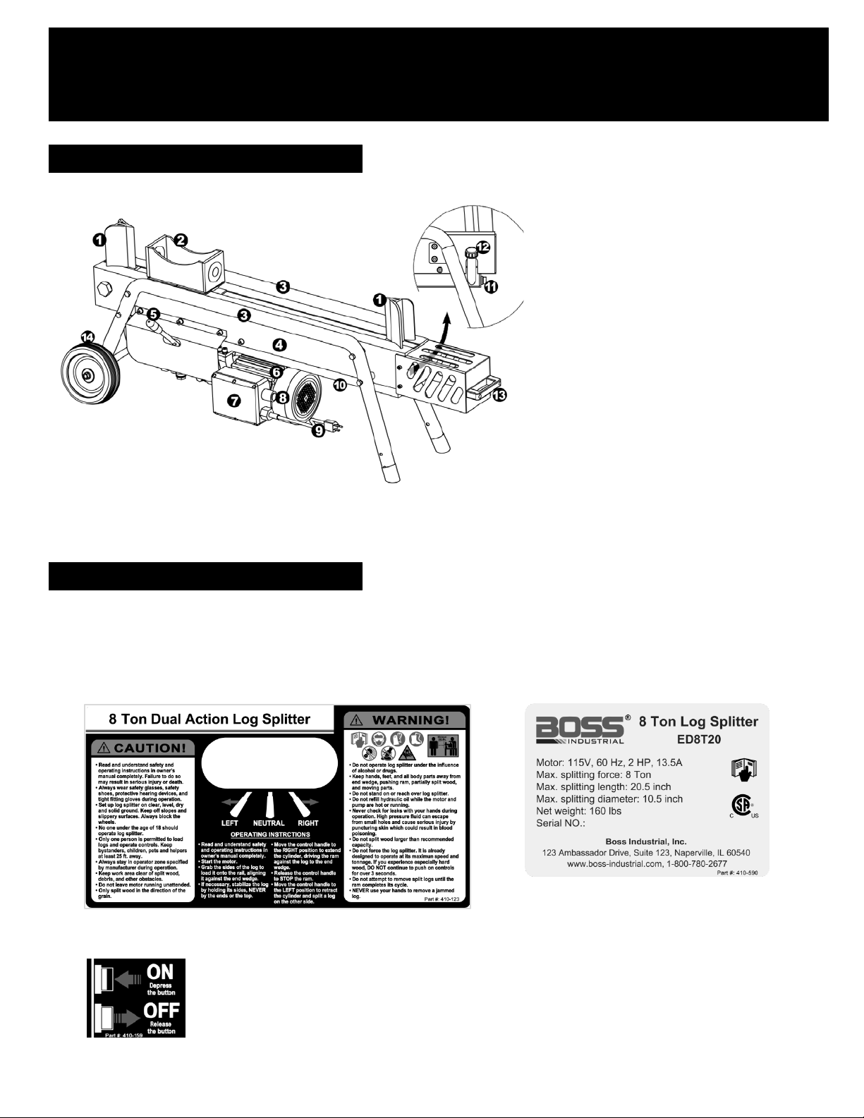
LOG SPLITTER OVERVIEW
SAF ETY DECALS
SECTION I: KNOW YOUR LO G SPLITTER
1. End wedge
2. Sliding ram
3. Log rail w/ legs
4. Machine body
5. Control handle
6. 115v, 2hp motor
7. Motor control box
8. Switch
9. Power cable with plug
10. Oil reservoir
11. Oil drain bolt
12. Dipstick w/ breather cap
13. Towing handle
14. Wheel
Make sure that all safety warning decals are in good condition and readable. Always replace missing or defaced decals.
Contact Boss Industrial, Inc. at 1-800-780-2677 for replacement decals.
1. Safety Warning / Operating Label (Part #: 410-123) 2. Serial NO. / Spec. Label (Part #: 410-590)
3. Switch Label (Part #: 410-159)
1
Page 5

2
4. Motor Label (Part #: 410-359) 5. Oil Tag (Part #: 410-602)
Study the following symbols used on this tool and learn their meaning. Proper interpretation of these symbols will
allow you to operate the tool better and safer.
Wet Conditions Alert Do not expose to rain or use in damp locations.
Read The Operator’s Manual
Eye, Face & Ear Protection
Safety Alert Precautions that involve your safety.
Wear Gloves
Wear Safety Footwear
Keep Bystanders Away Always keep bystanders at least 25 ft. (7.5 m) away.
Keep Hands Away Always keep hands away from the wedge and the ram.
To reduce the risk of injury, user must read and understand
operator’s manual before using this product.
Always wear safety goggles or safety glasses with side
shields, earplugs and a face shield when operating this
product.
Always wear nonslip, heavy-duty protective gloves when
operating this product.
Always wear nonslip safety footwear when operating this
product.
Pinch Point
Rotating & Moving Parts Alert
Electric Shock Alert
Never touch the cylinder bed, ram, or wedge during machine
operation.
Beware of rotating and moving parts, serious injury could
occur.
Never touch damaged or exposed wires while the machine is
connected to a power source.
Page 6

The following signal words and meanings are intended to explain the levels of risk associated with this product.
IMPORTANT TIPS
OPERATOR ZONE
(FIGURE 2)
Operator Zone
DANGER indicates a hazardous situation which, if not followed, will
result in serious injury or death.
WA RNING indicates a hazardous situation which, if not avoided, could
result in serious injury or death.
CAUTION indicates a hazardous situation which, if not avoided,
could result in minor or moderate i njury.
NOTICE is important information abo u t th e proper use of your
machine. Failure to follow this i n struction could result in damage to
your machine.
1. DO NOT discard packing materials until you have carefully inspected and satisfactorily operated the tool.
2. Make sure to replace the transportation seal plug at the oil filling port with the breather cap mounted on di p s tick.
Failure to do so may cause the pressure to build up in the reservoir which could dam age seals and void warranty.
3. Lubricate the wedge and upper side of the machine body for splitting smoothly.
4. Check the oil level before every operation.
5. Sharpen the wedges periodically.
6. USE only an electrical circuit having adequate capacity as recommended.
7. DO NOT continue to push on the control handle more than 3 seconds if the wedge can’t cut through an oversized
or extremely hard log. Force the tool will cause permanent damage and void warranty.
8. Try to split from another end or cut a small piece from the border instead of the center when you fail to cut
through a log.
9. Release the handle lever as the cylinder is almost extended or retracted fully. Keep holding the control lever as the
ram reaches to the farthest positions will cause the valve squeezed. You must turn off the motor to relieve the
pressure and restart the tool to operate.
10. DO NOT expose this machine to rain or use in a damp environment.
ONLY operate the log splitter from the operator zone as shown below. The operator has the safest and most efficient
access to the contro l valve and the beam in this location. Failure to operate the log splitter i n this position can result in
serious injury or death.
3
Page 7

Length
100'
10
10
10
— — —
ELECTRICAL SAFETY
(FIGURE 3)
1. This tool is powered by a precision built electric motor
. Use only an electrical circuit having ade qua te cap a cit y as
recommended by the manufacturer -- 115 volts, 60 Hz, AC only(normal household current). Do not operate this tool
on direct current (DC). If you choose to connect the tool to a generator, make sure the generator carrying the current
(Amperes) or power output (Watts) at least 50% more than motor rated power.
2. A substantial voltage drop will cause a loss of power and the motor will overheat. If the machine does not operate when
plugged into an outlet, double check the power supply.
3. For voltage, the wiring is as important as the motor’s horsepower rating. A line intended only for lights cannot properly
carry a power tool motor. Check the house wiring if you experience circuit breaker tripped or fuse blown even the
motor is plugged into a wall outlet directly, or switch to a 20 A circuit if this happens on a 15 A circuit.
4. This tool is intended for use on a circuit that has an outlet like the one shown below (FIGURE 3). Ensure that the outlet
has a grounding pin that is properly installed and grou nded in accor danc e with all loca l codes and ordi nanc e s
the risk of electric shock.
Check with a qualified electrician or service personnel if the grounding instructions are not
to reduce
completely understood, or if in doubt as to whether the tool is properly grounded.
5. Check that the switch, cable and plug are not damaged before each use to avoid electric shock or short circuit.
6. Use only 3-wire extension cords with 3-prong grounding plugs, and 3-pole receptacles that accept the tool's plug.
7. When using a power tool at a considerable distance from the power source, use an extension cord heavy enough to carry
the current that the tool will draw. An undersized extension cord will cause a drop in line voltage, resulting in a loss of
power and causing the motor to overheat.
8. Use the chart provided below to determine the minimum wire size required in an extension cord. Only round jacketed
cords listed by Underwriter's Laboratories (UL) should be used.
**Ampere rating (on tool faceplate)
0-2.0 2.1-3.4 3.5-5.0 5.1-7.0 1-12.0 12.1-16.0
Cord
Wire Size (A.W.G.)
25' 14 14 12 12 10 10
50' 12 12 10 10 — —
** Used on 14 gauge - 15 amp circuit,. Or 12 gauge - 20 amp circuit..
NOTE: AWG = American Wire Gauge
9. When working with the tool outdoors, use an extension cord that is designed for outside use. This is indicated by the
letters "WA" on the cord's jacket.
10. Keep the extension cord clear of the working area. Position the cord so that it will not get caught on lumber, tools or
other obstructions while you are working with a power tool. Failure to do so can result in serious injury.
11. “BLOWING” a fuse or tripping a circuit breaker is usually a warning that you are overloading the machine or have too
many devices taking power from the circuit, or both. DO NOT install a higher capacity fuse!
12. DO NOT leave the motor running unattended.
13. DO NOT expose the motor to rain or use / store in damp locations.
4
Page 8

HYDRAULIC SAFETY
The hydraulic system of your log splitter requires careful inspection along with the mechanical parts. Be sure to replace
1.
frayed, kinked, cracked or otherwise damaged hydraulic hoses or hydraulic components.
2. NEVER check for leaks of hydraulic fluid with your hand. Fluid escaping from a small hole can be almost invisible.
Escaping fluid under pressure can have sufficient force to penetrate skin causing serious personal injury or even death.
Leaks can be detected by passing a piece of cardboard over the suspected leak and looking for discoloration.
3. ALWAYS seek professional medical attention immediately if injured by escaping hydraulic fluid. Serious infection or
reaction can develop if proper medical treatment is not administered immediately.
4. ALWAYS be sure to relieve all pressure by shutting off the motor and moving the control handle back to stop position.
5. NEVER remove the vent plug from the hydraulic tank or reservoir while the log splitter is running. The tank could contain
hot oil under pressure which could result in serious injury.
6. NEVER adjust the hydraulic valve. The pressure relief valve on your log splitter is preset at the factory. Only a qualified
service technician should perform this adjustment.
7. NEVER operate your log splitter near a flame or spark. Hydraulic oil is flammable and can explode.
8. ALWAYS take a Class B fire extinguisher with you when operating this log splitter in dry areas as a precautionary
measure against possible flying sparks.
CALIFORNIA PROPOSITION 65
WARNING! Engine Exhaust, some of its constituents, and certain components contain
or emit chemicals known to State of California to cause cancer and birth defects or
other reproductive harm. For more information, please go to www.P65Warnings.ca.gov.
5
Page 9

UNPACKING & ASSEMBLING
(FIGURE 4)
SECTION II: PRE-OPERATIO N INSTRUCTIONS
This product has been shipped almost fully assembled.
• Carefully remove the log splitter and all accessories from the box. Make sure that all com ponents listed in the
packing List are included. See Page 16
• Inspect the tool carefully to make sure no breakage or damage occurred during shipping.
• DO NOT discard packing materials until you have carefully inspected and satisfactorily operated the tool.
• If any parts are damaged or missing, please call 1-800-780-2677 for assistance.
• Screw on the control handle lever onto the short lever on the valve. See FIGUR E 4
• Attach the safety shield. See FIGURE 4
• Replace the transportation seal plug at the oil filling port with the breather cap mounted on the dipstick.
See FIGURE 5
(FIGURE 5)
NOTES:
1. If any parts are dam aged or m issing, d o not operate this tool until the m issing parts are r epl aced. F ailure to do so
could result in possible serious personal injury.
2. Do not attempt to modify this tool or create accessories not recommended for use with this tool. Any such
alteration or modification is misuse and could result in a hazardous condition leading to possible serious personal
injury.
6
Page 10

GETTING PREPARED
(FIGURE 6)
• Check the oil level. See FIGURE 6
1) Remove the breather cap mounted on dipstick.
Wipe the dipstick and insert it all the way back
2)
into the oil filling tube.
3) Take out the dipstick and see if the oil level is
between the “OK” range.
4) Add oil (AW32) if the oil level is underneath the
bottom line until the proper level is reached.
• Place the log splitter on flat, dry, solid ground.
• Block two wheels to prevent your log splitter from
moving during operation.
• Lubricate the wedge and upper side of the machine
body.
the surface. See FIGURE 7
• Wear non-slip safety shoes, safety goggles, safety
gloves, protective hair covering and suitable work
clothing. Never wear jewelry, necktie and other
loose clothing.
• Logs should be cut with square ends. Never split logs
larger than 10.5 in. diameter or 20-1/2 in. long. Uneven
logs (e.g. knotted, curved, etc.) should not be used.
NOTES:
1. ALWAYS read the operator’s manual before operation.
2. NEVER allow children to operate this log splitt er. NEVER allow adults lacking pr oper instructio ns and under standing to
3. NEVER operate the log splitter when t ired or under the influence of alcohol, drugs or medication.
4. Always use eye protection which is marked to comply with ANSI Z87.1.
5. NEVER use this log splitter f or any purpose oth er than splitting wood. It is des igned f or this use onl y. An y other use can
6. Check that the s witch, p ow er cab le and plu g are n ot d am aged (no crac ks, et c.) to pre vent the r isk of electric s hock or a
7. Check that all nuts, bolts and hydraulic fittings are tight to be sure the equipment is in a safe working condition.
8. Ensure that the horizontal distance between the splitter and outlet is more than 5 feet.
9. Be familiar with al l c ontr o ls and pr op er operat io n. Kn o w ho w t o s t op the machine quickly in the event of any malfunct ion
7
This will allow the log to move smoothly on
operate this log splitter.
cause serious injury or death.
short circuit.
or emergency.
(FIGURE 7)
Page 11

(FIGURE 8)
• Plug the machine into a 3 pole outlet and start the
• Grab the round side of the log and place it firmly
against the wedge. See FIGURE 8
• Use your left hand to move the control handle left
• Stabilize the log usin g your right hand when nee ded.
• Release the control handle to stop splitting at any
• When you finish splitting, switch off and unp lug the
NOTES
1. NEVER place hands or feet between the extending wedge and the end plates.
2. NEVER straddle or step over the log splitter during operation.
3. NEVER reach or bend over the log splitter to pick up a log.
4. NEVER try to split two logs on top of each other.
5. NEVER try to cross split a log.
6. NEVER attempt to load your log splitter when the ram is in motion.
7. ALWAYS use your han d to oper at e th e c ontrol lever on the valve. N EV ER us e you r foot, a rope or any extens ion de v ic e.
8. ONLY operate your log splitter in daylight or under good artificial light.
9. ALWAYS keep the work area clean. Remove sp lit wood around your log splitter imm ediately so that you don’t stum ble
10. Only a single operator is a llowed to load and operate this log splitter. Ke ep bystanders, helpers, pets and childr en a
11. DO NOT f orce the tool. It is designed to operate within its max imum speed an d tonnage. No continuing to push on the
12. If the log is clipped or jamm ed on the wedg e, stop th e mac hine and k nock off the lo g with a ham mer or mallet (not with
13. DO NOT pull on the power supply cable to unplug the machine.
SECTION III: OPERATION INSTRUCTIONS
Motor.
or right to split the log.
Remove your hand immediately as the ram starts to
contact the log.
desired position and begin loading the next log.
DO NOT keep holding the control handle when the
ram reaches to the farthest positions.
power cable.
over it.
sufficient distance at least 25 feet from the machine.
control handle for m ore than 3 seconds. If you experi ence extremely hard wood , release the control ha ndle at once to
avoid permanent dam age which will vo id warr anty. If the motor stops, turn off the motor and then turn it back on again to
continue splitting.
your hands).
8
8
Page 12

OFF SEASON STORAGE
TRANSPORTATION
MAINTENANCE
(FIGURE 9)
Store unit in a clean, dry area. Make sure it’s switched off and unplugged.
NOTES
1. Allow the machine to cool 5 minutes after use before storing.
2. Protect power supply cable from heat, sunshine, aggressive liquids and sharp edges.
3. Do not store unit in unprotected areas outdoors. Never place near corrosive materials or in a damp environment.
4. Lean the machine against the wall if you store the machine upright. Make sure it won’t tip over.
This machine can fit in m ost pickup truck s or larger vehicles f or transportation. Ensure that the splitter is properly secured
before the vehicle is in motion.
NOTES
1. NEVER move this machine while the motor is running.
2. Be extra cautious when moving this machine on rugged and rough terrain.
3. Never allow anyone to ride on the machine while transporting.
4. Make sure the transportation seal plug is inserted into the oil filling tube during transportation.
SECTION IV: MAINTENANCE
Regular maintenance is the way to ensure the best performance and long life of your machine.
• Replace hydraulic oil every 100 hours of use. AW32 universal hydraulic oil is highly recommended.
1) Raise the wheel end of the splitter 10 in.
off the ground.
2) Place a container no less than 1.5 gallon
of capacity under the o il drain por t in the
front of the reservoir.
3) Using a 19mm wrench or an adjustable
wrench to remove the oil drain bolt. Also
disconnect the dipstick with breather cap
and safety shield to drain the oil easily.
4) Replace the oil drain bolt and tighten.
after the oil is completely drained.
5) Level the machine and refill the reservoir
tank with fresh oil via the oil filling tube
until the oil level reaches the max. line on
the dipstick. See FIGURE 6 on
9
See FIGURE 9
Page 7.
Page 13

6) Push the dipstick all the way in and operate the unit unloaded. Move the control handle to engage the ram close
Motor fails to start.
• Overload Protection Device disengaged to
• Switch off the motor and unplug the power
The log splitter won’t split
• Log is improperly positioned.
• Refer to Operation section for log loading.
Ram jerks, vibrates or
• Low oil level.
• Check oil level for possible oil refilling.
Oil leaks from points of
• Air is sealed in hydraulic system while
• Breather is blocked. Pull out the breather
TROUBLE SHOOTING
to the farthest positio ns back and forth for 12 cycles to repel the air.
7) Dispose old oil at an oil recycling center.
• Sharpen the wedge wh en it gets dull or nicked. Using a f ine-toothed file, smooth any burrs or crushed areas along the
cutting edge.
• Periodically clean the machine using an oiled rag to prevent rust.
• Do not at any time let brak e f luids, gas olin e, petrol eum based prod ucts , penetr ating lubricants , etc ., com e in cont act w ith
plastic parts. Chemicals can damage, weaken or destroy plastic which may result in serious personal injury.
• ALWAYS unplug from the power source while repairing or adjusting the splitter.
• Replace all damaged or worn parts immediately that must meet manufacturer’s specifications.
Most problems are easy to fix. Consult the trouble shooting Table below for common problems and their solutions.
unusual noise or vibrat ion i s genera ll y a warning of tr ouble. Ch eck for dam aged p arts and c lean , rep airs and / or replace
An
as
necessary. If you conti nue to experience prob lems, contact us at www.boss-industrial.com, call toll-f ree (800) 780 2677 or
send an email to service@boss-industrial.com for support.
Problem Possible Cause Remedy
logs.
does not move.
protect the log splitter from being damaged.
• The size or hardness of the log exceeds the
machine’s capacity.
• Wedge cutting edge is blunt.
• Insufficient hydraulic oil.
• Unauthorized adjustment was made on the
Maximum Pressure Set Screw. The pressure
was set lower.
• Extension cable of insufficient A.W.G.
• Ram is over held at the farthest positions
which
causes valve squeezed.
• Excessive air trapped in the hydraulic system.
• Log splitter is over forced.
• Hydraulic lines blocked .
• Hydraulic fluid too thick or too cold.
• Ram is overtightened to the bottom.
cable. Let motor cool down for 5 min and
restart. If this does not solve the problem,
call us for support.
• Reduce the log size before splitting
• Refer to “Sharpening The Wedge” in the
Maintenance section.
• Locate leak(s). Contact us for support.
• Contact us for support.
.
• Change an extension cable of higher
A.W.G.
• Turn off the motor and then restart to
release the pressure,
• Operate 12 cycles to repel air.
• Turn off and restart the unit. If this doesn’t
solve the problem, contact us for support.
• Change oil and clean or replace filter.
• Change wrong oil or warm up.
• Loosen the bolts mounted to the cylinder.
the hydraulic system
• Tank is overfilled.
• Transportation seal plug is not applied before
• Oil drain bolt is not tight.
• Hydraulic fitting(s) and/or seal(s) are worn.
operating.
moving the log splitter.
during operating.
• Put a container under the oil filling tube
until it stops spilling oil.
• Replace the transportation seal plug
before moving the log splitter.
• Tighten the oil drain bolt.
• Contact the dealer.
10
Page 14

TECHNICAL SPECIFICATIONS
Electrical requirements 115V, 60Hz
Power output 1500W
Rated current 13.5A
Motor speed 3400 RPM
Power cable SJTW 14 AWG (2.08mm²)
Max. splitting force* 8 ton
Max. splitting length 20.5 in
Splitting wedge height 5.25 in
Hydraulic pressure 3400 PSI
Cylinder bore * Stroke 2.5 in * 18.5 in
Feed 9 sec
Cycle time*
Retract 13 sec
Oil capacity (Included) 3 QT.
Machine dimensions (L×W×H) (in) 51.5x13.5x21
Machine net weight 160 lbs
*Tonnage and cycle time may vary dependent upon electricity supply, mechanical and
environmental conditions.
11
Page 15

EXPLODED DIAGRAM & PARTS LIST
Right
Left
Up
Back
Front
Down
12
Page 16

REF # PART # PART NAME SPECIFICATIONS QTY PER SECTION
1 310-874 Machine Body w/ End Plates 8T 1
2 710-614 Inner Hex Head Bolt ZP, M8*15 6
3 750-834 Spring Washer ZP, M8 6
4 750-638 Flat Washer ZP, M8 6
5 530-447 Ram 1
6 530-801 Upper Nylon Cushion 2
7 530-802 Lower Nylon Cushion 2
8 720-884 Lock Nut PH, M14 4
9 750-300 Flat Washer PH, M14 4
10 530-493 Hydraulic Cylinder Ø63*473 1
11 760-175 Clevis Pin ZP, M24*140 1
12 750-634 Flat Washer ZP, M24 1
13 720-845 Side bored nut ZP, M24 1
14 760-721 Split Pin ZP, Ø4*45 1
15 540-974 Reservoir Tank New 8T 1
16 540-276 Dipstick w/ Ventilator ABS Ventilator, Dipstick: Ø5*77 1
17 730-655 O Seal Ring Ø15*3.1 2
18 710-872 Oil Drain Bolt PH, M14*12 1
19 750-158 Copper Seal Washer M14 1
20 560-416 Hydraulic Hose for B-Cavity SA-19/B-14, 3/8 * 375 1
21 560-418 Hydraulic Hose for A-Cavity SA-19/B-14, 3/8 * 300 1
22 710-896 Oil Tube Screw PH, M14*30 2
23 750-158 Copper Seal Washer M14 2
24 710-991 Inner Hex Head Bolt PH, M8 *55 2
25 750-075 Spring Washer PH, M8 2
26 750-160 Flat Washer PH, M8 2
27 730-624 O Seal Ring Ø18*1.9 2
28 520-767 Hydraulic valve 8T 1
29 520-683 Short Lever Ø12.7*153.5 1
30 730-564 O Seal Ring Ø20*1.9 1
31 560-535 Connecting Oil Tube B-14/B-16, Ø10*182 1
32 750-565 Copper Seal Washer M16 1
33 710-838 Oil Tube Screw PH, M16*30 1
34 750-158 Copper Seal Washer M14 1
35 710-896 Oil Tube Screw PH, M14*30 1
36 730-624 O Seal Ring Ø18*1.9 1
37 710-895 Inner Hex Head Bolt PH, M8 * 20 4
38 730-624 O Seal Ring Ø18*1.9 4
39 550-203 Hydraulic pump 5.5 1
40 730-624 O Seal Ring Ø18*1.9 1
41 560-578 Oil Suction Tube B-14 x 2, Ø10*68 1
42 710-896 Oil Tube Screw PH, M14*30 2
43 750-158 Copper Seal Washer M14 2
44 730-088 O Seal Ring Ø24*2.4 1
45 540-038 Oil Filter Hex27 1
46 560-566 Oil Return Tube B-16 x 2, Ø10*80 1
47 710-838 Oil Tube Screw PH, M16*30 2
48 750-565 Copper Seal Washer M16 2
13
Page 17

REF # PART # PA RT NAME SPECIFICATIONS QTY PER SECTION
49 730-564 O Seal Ring Ø20*1.9 2
50 710-039 Inner Hex Head Bolt PH, M8 * 35 4
51 750-075 Spring Washer PH, M8 4
52 750-160 Flat Washer PH, M8 4
53 910-257 Motor Rear Cover 80 1
54 910-256 Electric Motor, Main Body 2 HP 1
55 920-011 Connecting Box (Bottom) 1
56 920-506 Connecting Box (Rubber Ring) 1
57 920-853 Connecting Box (Cover) 1
58 740-477 Cross Recess Pan Head Screw ZP, M4*10 6
59 920-943 Power Switch, Non-Homing 1
60 920-980 Capacitor 60uf 1
61 930-880 Cable Fastener 1
62 930-511 Cable Bushing 1
63 930-182 Power Cable STJW 3/C 14AWG, Ø2.08*1600 1
64 910-194 Fan 1
65 760-548 Circlip Ø16 1
66 910-154 Fan Cover Ø162 1
67 750-270 Flat Washer ZP, M4 3
68 740-477 Cross Recess Pan Head Screw ZP, M4*10 3
69 520-002 Control Handle Lever w/ Grip Ø12.7*220 (Female) 1
70 350-144 Position Shield (Right) 1
71 350-295 Position Shield (Left) 1
72 710-084 Inner Hex Head Bolt PH, M8 * 15 4
73 750-075 Spring Washer PH, M8 4
74 750-160 Flat Washer PH, M8 4
75 320-921 Joint Legs and Log Rail (Left) 1
76 320-920 Joint Legs and Log Rail (Right) 1
77 710-084 Inner Hex Head Bolt P H , M8 * 15 8
78 750-075 Spring Washer PH, M8 8
79 750-160 Flat Washer PH, M8 8
80 340-250 Axle Bushing Ø16*1.2*168 1
81 340-090 Wheel Axle Ø12.7*335 1
82 750-621 Flat Washer ZP, M12 2
83 330-214 Wheel 7”*1.8” 2
84 340-132 Bearing Spacer Ø 16*1.2*36.8 2
85 750-525 Flat washer ZP, M10 2
86 720-120 Lock Nut ZP, M10 2
87 320-825 Bumper 2
88 350-779 Safe Shield 1
89 710-879 Inner Hex Head Bolt PH, M8 * 12 4
90 750-075 Spring Washer PH, M8 4
91 750-160 Flat Washer PH, M8 4
92 320-511 Towing Handle 1
93 750-273 Flat washer ZP, M6 2
94 750-823 Spring Washer ZP, M6 2
95 740-327 Cross Recess Pan Head Screw ZP, M6*20 2
53-68 940-611 Whole Motor 2 HP 1
14
Page 18

WARRANTY
LIMITED WARRANTY STATEMENT
Boss Industrial, Inc., (“Boss Industrial”) warrants to the original retail purchaser that this BOSS brand outdoor product is
designed and made to the highest line standards applicable and agrees to repair or replace, at Boss Industrial’s,
discretion, any defective product in material and workmanship free of charge within these time periods from the date of
purchase under the limited warranty terms below.
• Two years for all models if used for personal, family, or household use;
• 180 days for any unit used for other purposes, such as rental or commercial.
This warranty extends to the original retail purchaser only and commences on the date of the original retail purchase.
Boss Industrial honors the return policy of registered retailors under the terms and conditions mutually specified and
agreed. Otherwise, any part of this product manufactured or supplied by Boss Industrial and found in the reasonable
judgment of Boss Industrial to be defective in material or workmanship will be repaired or replaced without charge for
parts and labor by Boss Industrial or its authorized service center. How to process a warranty claim? You must first call
the BOSS INDUSTRIAL service hotline 1 800 780 2677 or send email to service@boss-industrial.com. Proofs of purchase
will be required to substantiate any warranty claim. Our technical team will guide you in trouble shooting, repairing, or
returning a defective part or machine. Any unauthorized repair or return will invalidate this warranty. The expense of
delivering the replacement part or product to the dealer or Boss Industrial for warranty work and the expense of
returning it back to the owner after repair or replacement will be paid by the owner. Boss Industrial’s responsibility in
respect to claims is limited to making the required repairs or replacements and no claim of breach of warranty shall be
cause for cancellation or rescission of the contract of sale of any BOSS brand product. All warranty work must be
performed by Boss Industrial or its authorized service center.
This warranty is limited to one hundred eighty (180) days from the date of original retail purchase for any Boss Industrial
brand product that is used for rental or commercial purposes, or any other income-producing purpose.
This warranty does not cover any BOSS brand product that has been subject to misuse, negligence, or accident, or that
has been operated in any way contrary to the operating instructions as specified in this operator’s manual. This
warranty does not apply to any damage to the product that is the result of improper maintenance or to any product
that has been altered or modified. The warranty does not extend to repairs made necessary by normal wear or by the
use of parts or accessories which are either incompatible with the BOSS brand product or adversely affect its operation,
performance, or durability. In addition, this warranty does not cover:
A. Tune-ups – Switch, Capacitor, Cable fastener, Spark Plugs, Carburetors, Adjustments, Ignition, Filters, Handles
B. Wear items – Tires, nylon liners, rubber seals, rubber hoses, hydraulic oil
C. Gas Engines – as they are covered under the Engine Manufacturers’ Warranty.
Boss Industrial reserves the right to change or improve the design of any BOSS brand product without assuming any
obligation to modify any product previously manufactured.
ALL IMPLIED WARRANTIES ARE LIMITED IN DURATION TO THE STATED WARRANTY PERIOD. ACCORDINGLY, ANY SUCH
IMPLIED WARRANTIES INCLUDING MERCHANTABILITY, FITNESS FOR A PARTICULAR PURPOSE, OR OTHERWISE, ARE
DISCLAIMED IN THEIR ENTIRETY AFTER THE EXPIRATION OF THE APPROPRIATE TWO-YEAR, ONE-YEAR, OR NINETY-DAY
WARRANTY PERIOD. BOSS INDUSTRIAL’S OBLIGATION UNDER THIS WARRANTY IS STRICTLY AND EXCLUSIVELY LIMITED TO
THE REPAIR OR REPLACEMENT OF DEFECTIVE PARTS AND BOSS INDUSTRIAL DOES NOT ASSUME OR AUTHORIZE ANYONE
TO ASSUME FOR THEM ANY OTHER OBLIGATION. SOME STATES DO NOT ALLOW LIMITATIONS ON HOW LONG AN IMPLIED
WARRANTY LASTS, SO THE ABOVE LIMITATION MAY NOT APPLY TO YOU. BOSS INDUSTRIAL ASSUMES NO RESPONSIBILITY
FOR INCIDENTAL, CONSEQUENTIAL, OR OTHER DAMAGES INCLUDING, BUT NOT LIMITED TO, EXPENSE OF RETURNING THE
PRODUCT TO AN AUTHORIZED BOSS INDUSTRIAL SERVICE CENTER AND EXPENSE OF DELIVERING IT BACK TO THE OWNER,
MECHANIC’S TRAVEL TIME, TELEPHONE OR TELEGRAM CHARGES, RENTAL OF A LIKE PRODUCT DURING THE TIME
WARRANTY SERVICE IS BEING PERFORMED, TRAVEL, LOSS OR DAMAGE TO PERSONAL PROPERTY, LOSS OF REVENUE, LOSS
OF USE OF THE PRODUCT, LOSS OF TIME, OR INCONVENIENCE. SOME STATES DO NOT ALLOW THE EXCLUSION OR
LIMITATION OF INCIDENTAL OR CONSEQUENTIAL DAMAGES, SO THE ABOVE LIMITATION OR EXCLUSION MAY NOT APPLY
TO YOU.
This warranty gives you specific legal rights, and you may also have other rights which vary from state to state. This
warranty applies to all BOSS brand products manufactured by or for Boss Industrial and sold in the United States, Canada.
15
Page 19

(1) Log Splitter
(1) Control Handle Lever w/ Grip
(1) Safe Shield Assem bl y
PACKING LIST
(1) Operator’s Manual
(1) Dipstick w/ Breather Cap
16
Page 20

Boss Industrial, Inc. • 1208 N. Independence Blvd •
Romeoville, IL 60446 • USA
Phone: (800) 780-BOSS (2677) • Fax (331) 472-2976
www.boss-industrial.com
 Loading...