

Boss ES7T20, EC5T20 Owner's Manual

HORIZONTAL
Rev.2
ELECTRIC
7 TON LOG SPLITTER
MODEL NO.
ES7T20
Owner’s Manual
ASSEMBLY & OPERATI NG INSTRUCTIONS
Purchase Date___________________ Serial No.______________________
Dealer________________________________________________________
Boss Industrial, Inc. • 123 Ambassador Drive, Suite 123 • Naperville, IL 60540 • USA
Phone: (800) 780-BOSS (2677) • Fax (331) 472-2976
www.boss-industrial.com


To The Owner
Thank You!
Thank you for purchasing a BOSS Log Splitter. It was carefully engineered to provide excellent performance when properly
operated and maintained.
Please read this entire manual prior to operating the equipment. It instructs you how to safely and easily set up, operate
and maintain your machine. Please be sure that you, and any other persons who will operate the machine, carefully follow
the recommended safety practices at all times. Failure to do so could result in personal injury or property damage.
All information in this manual is relative to the most recent product information available at the time of printing. Review
this manual frequently to familiarize yourself with the machine, its features and operation. Please be aware that this
Operator’s Manual may cover a range of product specifications for various models. Characteristics and features discussed
and/or illustrated in this manual may not be applicable to all models. We reserve the right to change product specifications,
designs and equipment without notice and without incurring obligation.
The electric horizontal log splitter is designed to use on a power supply that is 115 volts, 60 Hz, AC only (normal household
current of 15 amp / 20 amp). If you have any problems or questions concerning the machine, phone an authorized service
dealer or contact us directly. Boss Industrial’s customer support phone number, website and mailing address can be found
on this page. We want to ensure your complete satisfaction at all times.
Boss Industrial reserves the right to discontinue, change, and improve its products at any time without notice or obligation
to the purchaser. The description and specifications contained in the manual were in effect at printing. Equipment
described within this manual may be optional. Some illustrations may not be applicable to your machine.
Throughout this manual, all references to right and left side of the machine are observed from the operating position.
Boss Industrial, Inc. is responsible for all equipment-related issues with regards to performance, power-rating,
specifications, warranty and service. Please refer to the Warranty terms included in this Owner’s/Operator’s Manual for
more information.
Customer Support
Please do NOT return the machine to the retailer or dealer without first contacting the Customer Support
Department.
If you have difficulty assembling this product or have any questions regarding the controls, operation, or maintenance of
this machine, you can seek help from the experts. Choose from the options below:
◊ Visit us on the web at www.boss-industrial.com
◊ Call a Customer Support Representative at (800) 780-2677 or (331) 457-5670
◊ Write to Boss Industrial, Inc., 123 Ambassador Drive, Suite 123, Naperville, IL 60540

Table of Contents
Page(s)
Important Safety Information ....................................................................................................................................1-6
Intended Use ...............................................................................................................................................1
Personal Protective Equipment ...................................................................................................................1
Safety Decals ...........................................................................................................................................1-4
Electrical Safet y ................. ..........................................................................................................................5
Log Splitter Overview ...................................................................................................................................6
General Safety .............................................................................................................................................7
Work Area ....................................................................................................................................................8
Operation of Log Splitter ..............................................................................................................................8
Maintenance Safety .....................................................................................................................................9
Hydraulic Safety .........................................................................................................................................10
Fire Prevention ...........................................................................................................................................10
Assembly Instructions ............................................................................................................................................11-12
Pre-Operation Instructions ..........................................................................................................................12
Operating Instructions ............................................................................................................................................13-14
Transportation .............................................................................................................................................14
Storage ........................................................................................................................................................14
Maintenance ...................... .....................................................................................................................................15-16
Troubleshooting ...........................................................................................................................................................17
Technical Specifications ..............................................................................................................................................18
Exploded Diagram & Parts List ...............................................................................................................................19-21
Warranty Information ...................................................................................................................................................22
Packing List .................................................................................................................................................................23

SAF ETY DECALS
PROTECTIVE EQUIPMENT
INTENDED USE
Page │ 1
WARNING: Read and thoroughly understand all instructions and safety information before assembling
or operating this log splitter. Failure to do so may cause serious injury or death. D o n o t allow anyone to
operate this log splitter who has n o t read this manual. As with all power equipment, a log splitter can be
dangerous if assembled or used im properly. Do not operate this log splitter if you have doubts or
questions concerning safe operation. Call our customer service department at 1-800-780-2677 to
address these concerns.
Si no entiende ingles, se prefiere que busque alguien que interprete las instrucciones para usted.
This safety alert symbol identifies important safety messages in this manual.
Failure to follow this important safety information may result in serious injury
or death.
INTENDED USE
NEVER use this log splitter for any purpose other than splitting wood. It is designed for this use only. Any other use can
cause serious injury or death.
PERSONAL PROTECTIVE EQUIPMENT
BEFORE operating this log splitter make sure that you wear safety gear such as goggles or safety glasses, steel toed
shoes and tight fitting gloves (without loose cuffs or draw strings). Always wear a protective hearing device when operating
this log splitter.
NEVER wear loose clothing or jewelry that can be caught by moving parts of the log splitter. Keep clothing and hair away
from all moving parts when operating this log splitter.
SAFETY DECALS
Make sure that all safety warning decals are in good condition and readable. Always replace missing or defaced decals.
Contact Boss Industrial, Inc. at 1-800-780-2677 for replacement decals.
Page | 1

Part #: 410-602
Part #: 410-561
159
Part #: 410-156 Part #: 410-359
Part #: 410-231
Part #: 410-
Part #: 410-265
Page | 2
Part #: 410-245
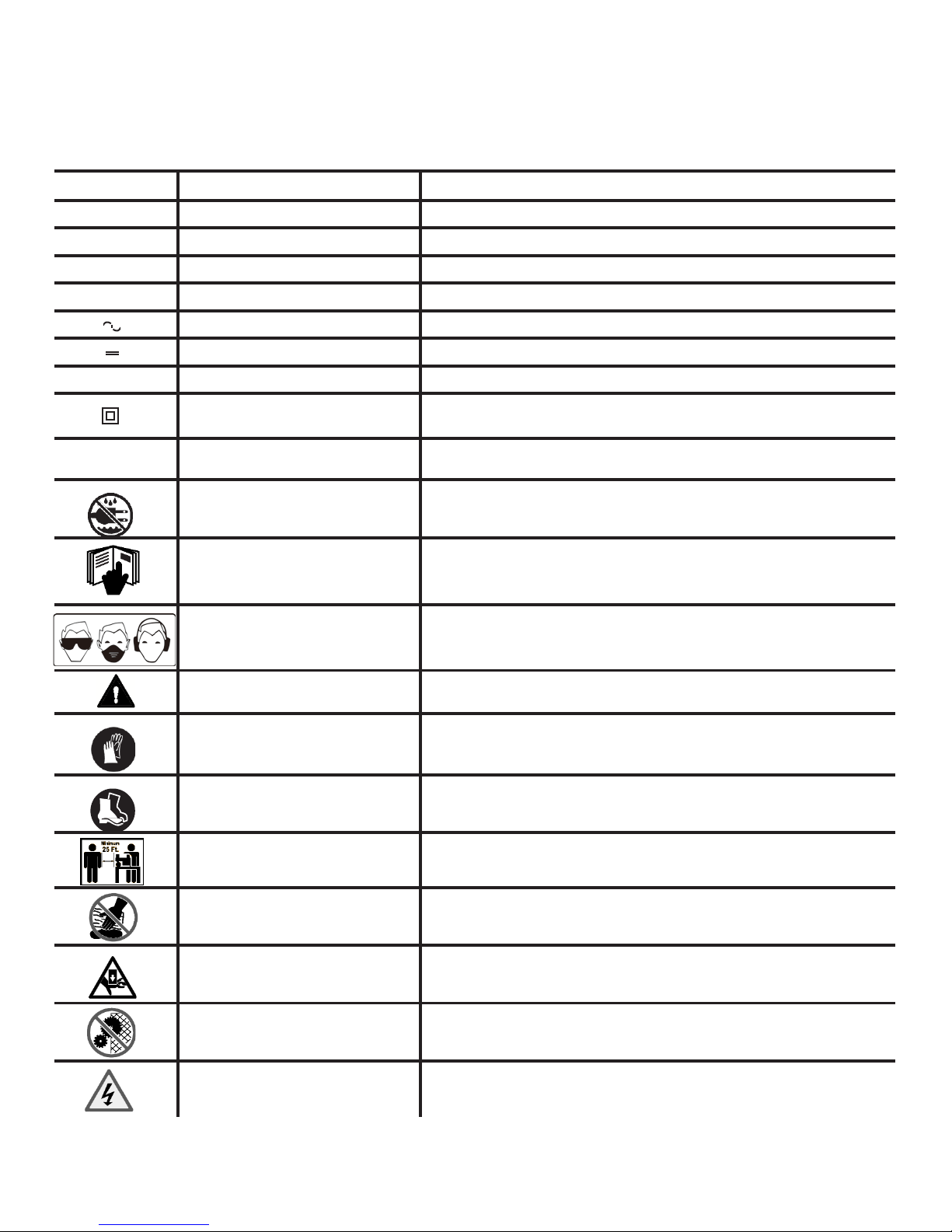
Some of the following symbols may be used on this tool. Please study them and learn their meaning. Proper
Page │ 3
interpretation of these symbols will allow you to operate the tool better and safer.
SYMBOL NAME DESIGNATION/EXPLANATION
V Volts Voltage
A Amperes Current
Hz Hertz Frequency (cycles per second)
W Watt Power
min Minutes Time
Alternating Current Type of current
Direct Current Type or a characteristic of current
no No Load Speed Rotational speed, at no load
Class II Construction Double-insulated construction
.../min Per Minute Revolutions, strokes, surface speed, orbits etc., per minute
Wet Conditions Alert Do not expose to rain or use in damp locations.
Read The Operator’s Manual
Eye, Face & Ear Protection
Safety Alert Precautions that involve your safety.
Wear Gloves
Wear Safety Footwear Always wear nonslip safety footwear when operating this product.
Keep Bystanders Away Always keep bystanders at least 25 ft. (7.5 m) away.
Keep Hands Away Always keep hands away from the wedge and the ram.
To reduce the risk of injury, user must read and understand
operator’s manual before using this product.
Always wear safety goggles or safety glasses with side shields,
earplugs and a face shield when operating this product.
Always wear nonslip, heavy-duty protective gloves when
operating this product.
Pinch Point
Rotating & Moving Parts Alert Beware of rotating and moving parts, serious injury could occur.
Electric Shock Alert
Page | 3
Never touch the cylinder bed, ram, or wedge during machine
operation.
Never touch damaged or exposed wires while the machine is
connected to a power source.

DANGER:
WARNING:
CAUTION:
damage.
The following signal words and meanings are intended to explain the levels of risk associated with this product.
SYMBOL SIGNAL MEANING
Indicates an imminently hazardous situation, which, if not avoided, will result
in death or serious injury.
Indicates a potentially hazardous situation, which, if not avoided, could result
in death or serious injury.
Indicates a potentially hazardous situation, which, if not avoided, may result in
CAUTION: (Without Safety Alert Symbol) Indicates a situation that may result in property
WARNING:
The operation of any power tool can result in foreign objects being thrown into your eyes, which can
result in severe eye d amage. Before beginning power tool operation, al ways wear safety gogg les or
safety glasses with side shields and, when needed, wear a full face shield and earplugs. We
recommend a W ide Vision Saf ety Mask f or use over eyeg lasses or sta ndard safet y glasses with s ide
shields. Always use eye protection which is marked to comply with ANSI Z87.1.
minor or moderate injury.
SAVE THESE INSTRUCTIONS
Page | 4
100'
12
12
10
10
10
—
GROUNDING INSTRUCTIONS
ELECTRICAL CONNECTION
ELECTRICAL SAFETY
Page │ 5
EXTENSION CORDS
Use only 3-wire extension cords that have 3-prong
grounding plugs and 3-pole receptacles that accept the
tool's plug. When using a power tool at a considerable
distance from the power source, use an extension cord
heavy enough to carry the current that the tool will draw. An
undersized extension cor d will cause a dro p in line voltage,
resulting in a loss of power and causing the motor to
overheat. Use the chart provided below to determine the
minimum wire size required in an extension cord. Only
round jacketed cords listed by Underwriter's Laboratories
(UL) should be used.
**Ampere rating (on tool faceplate)
Cord Length
25'
50'
**Used on 14 gauge - 15 amp circuit,. Or 12 gauge – 20 amp circuit
NOTE: AWG = American Wire Gauge
When working with the tool outdoors, use an extension
cord that is design ed for outside use. This is indicated by
the letters "WA" on the cord's jacket.
Before using an extension cord, inspect it for loose or
exposed wires and cut or worn insulation.
Keep the extension cord clear of the working area.
Position the cord so tha t it wil l not ge t caug ht on lum ber,
tools or other obstructions while you are working with a
power tool. Failure to do so can result in serious
personal injury.
0-2.0 2.1-3.4 3.5-5.0 5.1-7.0 7.1-12.0 12.1-16.0
Wire Size (A.W.G.)
14 14
14 14
14 12 12 12
12 12 10 10
WARNING:
WARNING:
Check extension cords before each use. If damaged
replace immediately. Never use tool with a damaged
cord since touching the damaged area could cause
electrical shock resulting in serious injury.
ELECTRICAL CONNECTION
This tool is powered b y a precision built electric motor. It
should be connected to a power supply that is 115 volts,
60 Hz, AC only (normal household current). Do not
operate this tool on direct current (DC). A substantial
voltage drop will caus e a loss of power and the moto r will
overheat. If the product does not operate when plugged
into an outlet, double check the power supply.
SPEED AND WIRING
The speed is not constant and decreases under a loa d or
with lower voltage . For voltage, the wiring in a shop is as
important as the motor ’s ho r s epo wer rat ing. A line i nte nded
only for lights cannot properly carry a power tool motor.
Wire that is heav y enough for a short distance wi ll be too
light for a greater distance. A line that can support one
power tool may not be able to support two or three tools.
In the event of a malfunction or breakdown, grounding
provides a path of least resistance for electric current to
reduce the r isk of electric shock. This tool is equipped with
an electric cord having an equipment-grounding
conductor and a grounding plug. The plug must be
plugged into a matching outlet that is properly installed
and grounded in accordance with all local codes and
GROUNDING INSTRUCTIONS
ordinances.
In the event of a malfunction or breakdown, grounding
Do not modify the plug provided. If it will not fit the outlet,
provides a path of least resistance for electric current to
have the proper outlet installed by a qualified electrician.
reduce the risk of electric shock. This tool is equipped with
Improper connection of the equipment-grounding
an electric cord having an equipment-gr ounding conduc tor
conductor can result in a risk of electric shock. The
and a grounding plug. The plug must be plugged into a
conductor with insulation having an outer surface that is
matching outlet that is properly installed and grounded in
green with or with
grounding conductor. If repair or replacement of the
accordance with all local codes and ordinances.
electric cord or plug is necessary, do not connect the
Do not modify the pl ug provided. If it will not fit t he outlet,
equipment-grounding conductor
have the proper outlet installed by a qualified electrician.
Check with a qualified elect ric ian or service personnel if the
Improper connection of t he equ ipment-grounding cond uc tor
grounding instructions are not completely understood, or
can result in a risk of electric shock. The conductor with
in doubt as to whether the tool is properly grounded.
insulation having an outer surface that is green with or with-
Repair or replace a damaged or worn cord immediately.
out yellow stripes is the equipment -grounding conductor . If
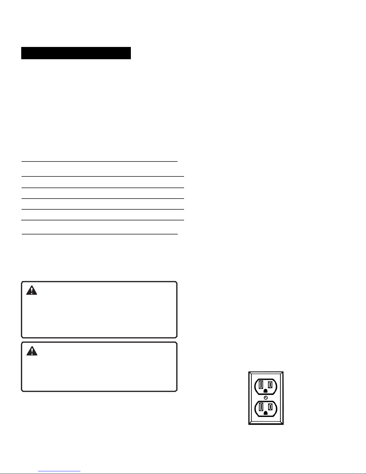
This tool is intended for use on a circuit that has an outlet
repair or replacement of the electric cord or plug is
like the one shown below. Ensure that the outlet has a
necessary, do not connect the equipment-grounding
grounding pin.
conductor to a live terminal.
Check with a qua lified e lec t r ician or s ervice personnel if the
grounding instructions ar e not completely understood, or if
in doubt as to whether the tool is properly grounded.
Repair or replace a damaged or worn cord
-
out yellow stripes is the equipment-
to a live terminal.
if
Page | 5
 Loading...