

Page 1
English
Deutsch
F
D
k
E
l
Itali
S
venska
Nederland
D
k
Itali
S
Deutsch
Nederland
English
F
E
l
s
ano
rançais
venska
spaño
s
ano
rançais
ans
spaño
SAFETY INFORMATION
Please read this owner’s guide
Please take the time to follow the instructions in this owner’s guide carefully. It will help you set up and operate your system
properly and enjoy all of its advanced features. Please save this owner’s guide for future reference.
WARNING: To reduce the risk of fire or electrical shock, do not expose the product to rain or moisture.
WARNING: The apparatus shall not be exposed to dripping or splashing, and objects filled with liquids, such as vases, shall not
be placed on the apparatus. As with any electronic product, use care not to spill liquids into any part of the system. Liquids can
cause a failure and/or a fire hazard
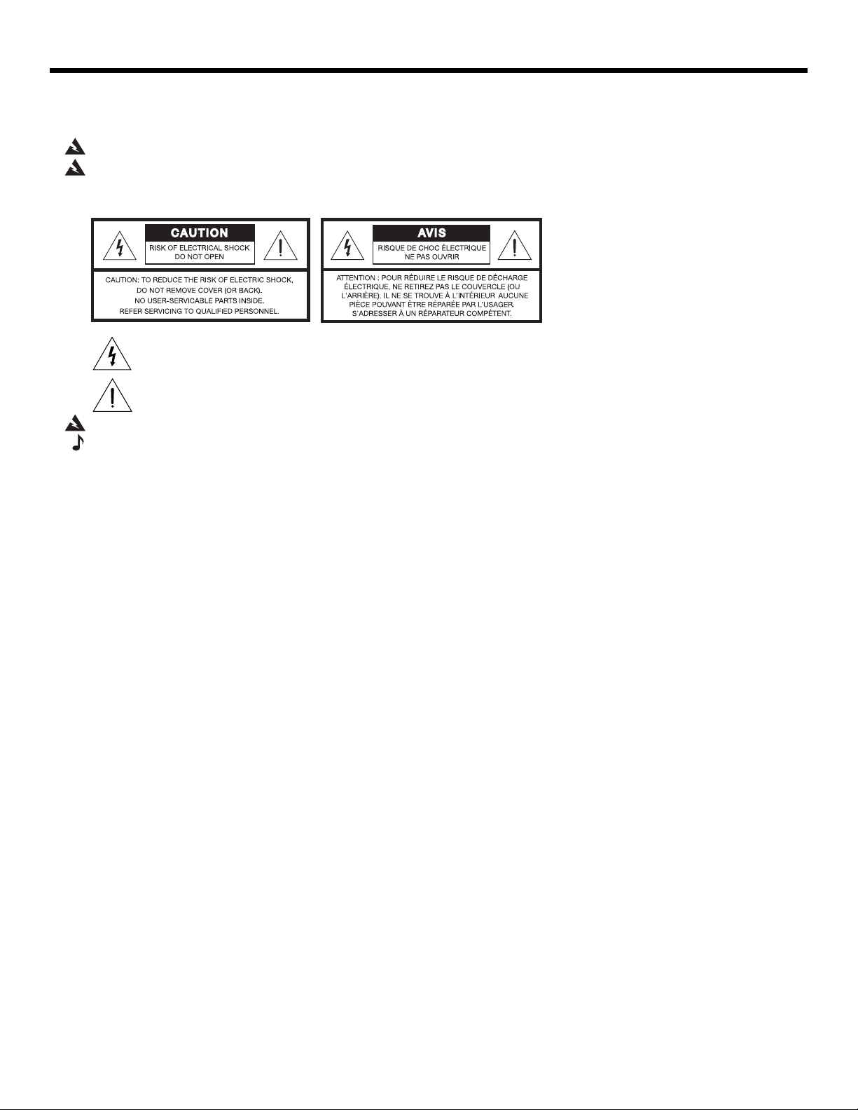
The lightning flash with arrowhead symbol, within an equilateral triangle, alerts the user to the presence of uninsulated
dangerous voltage within the system enclosure that may be of sufficient magnitude to constitute a risk of electric shock.
The exclamation point within an equilateral triangle alerts the user to the presence of important operating and maintenance instructions in this owner’s guide.
ans
WARNING: No naked flame sources, such as lighted candles, should be placed on the apparatus.
Note: The product label is located on the bottom of the product.
This product is intended to be used only with the power supply provided. Where the mains plug is used as the disconnect
device, such disconnect device shall remain readily operable
.
This product must be used indoors. It is neither designed or tested for use outdoors, in recreation vehicles, or on
boats.
Important safety instructions
1. Read these instructions – for all components before using this product.
2. Keep these instructions – for future reference.
3. Heed all warnings – on the product and in the owner’s guide.
4. Follow all instructions.
5. Do not use this apparatus near water or moisture – Do not use this product near a bathtub, washbowl, kitchen sink,
laundry tub, in a wet basement, near a swimming pool, or anywhere else that water or moisture are present.
6. Clean only with a dry cloth – and as directed by Bose Corporation. Unplug this product from the wall outlet before
cleaning.
7. Do not block any ventilation openings. Install in accordance with the manufacturer’s instructions – To ensure reliable
operation of the product and to protect it from overheating, put the product in a position and location that will not interfere
with its proper ventilation.
8. Do not install near any heat sources, such as radiators, heat registers, stoves or other apparatus (including
amplifiers) that produce heat.
9. Only use attachments/accessories specified by the manufacturer.
2
10. Unplug this apparatus during lightning storms or when unused for long periods of time – to prevent damage to this
product.
11. Refer all servicing to qualified service personnel. Servicing is required when the apparatus has been damaged in
any way: such as power supply cord or plug is damaged; liquid has been spilled or objects have fallen into the apparatus; the apparatus has been exposed to rain or moisture, does not operate normally, or has been dropped.
Page 2

English
Deutsch
F
D
k
E
l
Itali
S
Nederland
D
ans
k
Itali
S
Deutsch
Nederland
English
F
E
l
ans
spaño
ano
rançais
spaño
s
rançais
venska
ano
s
venska
CONTENTS
INTRODUCTION 4
The Bose® link AL8 Homewide Wireless Audio Link . . . . . . . . . . . . . . . . . . . . . . . . . . . . . . . . . . . . . . . . . . . . . . . . . . 4
Unpacking the carton . . . . . . . . . . . . . . . . . . . . . . . . . . . . . . . . . . . . . . . . . . . . . . . . . . . . . . . . . . . . . . . . . . . . . . . . . . 4
What distinguishes the two units . . . . . . . . . . . . . . . . . . . . . . . . . . . . . . . . . . . . . . . . . . . . . . . . . . . . . . . . . . . . 5
Choosing a place for each unit . . . . . . . . . . . . . . . . . . . . . . . . . . . . . . . . . . . . . . . . . . . . . . . . . . . . . . . . . . . . . . . . . . 5
SETUP 6
Making the connections . . . . . . . . . . . . . . . . . . . . . . . . . . . . . . . . . . . . . . . . . . . . . . . . . . . . . . . . . . . . . . . . . . . . . . . . 6
For the transmitter . . . . . . . . . . . . . . . . . . . . . . . . . . . . . . . . . . . . . . . . . . . . . . . . . . . . . . . . . . . . . . . . . . . . . . . 6
For the receiver . . . . . . . . . . . . . . . . . . . . . . . . . . . . . . . . . . . . . . . . . . . . . . . . . . . . . . . . . . . . . . . . . . . . . . . . . 7
Instructions for non-Bose or older Bose products . . . . . . . . . . . . . . . . . . . . . . . . . . . . . . . . . . . . . . . . . . . . . . . 7
Check the indicators and settings . . . . . . . . . . . . . . . . . . . . . . . . . . . . . . . . . . . . . . . . . . . . . . . . . . . . . . . . . . . . . . . . 8
The Status LED . . . . . . . . . . . . . . . . . . . . . . . . . . . . . . . . . . . . . . . . . . . . . . . . . . . . . . . . . . . . . . . . . . . . . . . . . . 8
The transmitter Channel button . . . . . . . . . . . . . . . . . . . . . . . . . . . . . . . . . . . . . . . . . . . . . . . . . . . . . . . . . . . . . 9
Your Bose
Your Bose link expansion room product . . . . . . . . . . . . . . . . . . . . . . . . . . . . . . . . . . . . . . . . . . . . . . . . . . . . . . 9
Your Bose link expansion room system . . . . . . . . . . . . . . . . . . . . . . . . . . . . . . . . . . . . . . . . . . . . . . . . . . . . . . . 9
Enjoy your wireless entertainment . . . . . . . . . . . . . . . . . . . . . . . . . . . . . . . . . . . . . . . . . . . . . . . . . . . . . . . . . . . . . . . . 9
®
link expansion room remote control . . . . . . . . . . . . . . . . . . . . . . . . . . . . . . . . . . . . . . . . . . . . . . . . 9
REFERENCE 10
Accessories . . . . . . . . . . . . . . . . . . . . . . . . . . . . . . . . . . . . . . . . . . . . . . . . . . . . . . . . . . . . . . . . . . . . . . . . . . . . . . . . . 10
Troubleshooting . . . . . . . . . . . . . . . . . . . . . . . . . . . . . . . . . . . . . . . . . . . . . . . . . . . . . . . . . . . . . . . . . . . . . . . . . . . . . . 10
Contacting Customer Service . . . . . . . . . . . . . . . . . . . . . . . . . . . . . . . . . . . . . . . . . . . . . . . . . . . . . . . . . . . . . . 11
Limited warranty . . . . . . . . . . . . . . . . . . . . . . . . . . . . . . . . . . . . . . . . . . . . . . . . . . . . . . . . . . . . . . . . . . . . . . . . . . . . . . 11
Technical Information . . . . . . . . . . . . . . . . . . . . . . . . . . . . . . . . . . . . . . . . . . . . . . . . . . . . . . . . . . . . . . . . . . . . . . . . . . 11
Information about products that generate electrical noise
U.S.A.
This equipment has been tested and found to comply with the limits for a Class B digital device, pursuant to Part 15 of the FCC rules.
These limits are designed to provide reasonable protection against harmful interference in a residential installation. This equipment
generates, uses, and can radiate radio frequency energy and, if not installed and used in accordance with the instructions, may cause
harmful interference to radio communications. However, this is no guarantee that interference will not occur in a particular installation.
If this equipment does cause harmful interference to radio or television reception, which can be determined by turning the equipment off
and on, you are encouraged to try to correct the interference by one or more of the following measures:
• Reorient or relocate the receiving antenna.
• Increase the separation between the equipment and receiver.
• Connect the equipment to an outlet on a different circuit than the one to which the receiver is connected.
• Consult the dealer or an experienced radio/TV technician for help.
Any modifications made to this equipment may void the user’s authority to operate this equipment.
Canada
This product complies with the Canadian ICES-003 Class B specification.
Operation is subject to the following two conditions: (1) this device may not cause interference and (2) this device must accept any
interference, including interference that may cause undesired operation of the device.
For Your Records
Serial numbers are located on the bottom of the AL8 transmitter and the receiver.
Serial numbers: Transmitter _____________________________________ Receiver _________________________________________________
Dealer name: ____________________________________________________________________________________________________________
Dealer phone: ________________________________________________ Purchase date: ____________________________________________
Bose recommends that you keep your sales slip and a copy of your product registration card together with this guide.
3
Page 3
English
Deutsch
F
D
k
E
l
Itali
S
venska
Nederland
D
k
Itali
S
Deutsch
Nederland
English
F
E
l
T
s
ano
rançais
venska
spaño
s
INTRODUCTION
The Bose® link AL8 Homewide Wireless Audio Link
Congratulations on your choice of Bose to provide an audio expansion solution free from the
need to run cumbersome wires between rooms.
The audio link consists of a transmitter and receiver. They deliver audio signals from your
LIFESTYLE
house to the system or speakers you have set up another area.
One transmitter can also send signals to as many as 8 receivers, making it simple to add on
to your system whenever you like.
Note: For future expansion possibilities, we recommend that you keep this owner’s guide as a
reference.
In combination with a Bose link remote control or the PERSONAL
link AL8 Homewide Wireless Audio Link gives you numerous options for expanding your
enjoyment.
Unpacking the carton
Carefully unpack the carton and save all packing materials for possible future use. They
provide the most secure way to transport the product.
®
18 or 28 Series II system or LIFESTYLE® 38 or 48 system in one area of your
ano
rançais
ans
spaño
®
music center II, the Bose®
ans
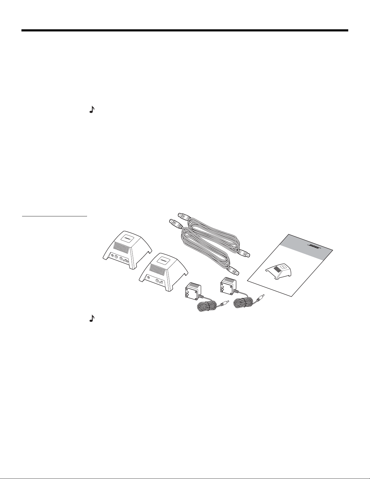
Figure 1
Carton contents
Check to be sure your system includes all of the parts shown (Figure 1). If any part appears
damaged, do not attempt to use it. Notify Bose or your authorized Bose dealer immediately.
For Bose contact information, refer to the address sheet included in the carton.
Bose link A
cables
ransmitter
Power
packs
Receiver
Owner’s
guide
Ooooooooo
Note: Now is a good time to find the serial numbers on the bottom of the transmitter and the
receiver. Copy them onto your product registration card and in the space provided on “For Your
Records” on page 3.
4
Page 4

English
Deutsch
F
D
k
E
l
Itali
S
Nederland
D
ans
k
Itali
S
Deutsch
Nederland
English
F
E
l
spaño
Figure 2
Connection panels on the
two units
ans
ano
rançais
spaño
s
rançais
venska
ano
s
venska
INTRODUCTION
What distinguishes the two units
The connection panel on each unit identifies it by name: TRANSMITTER or RECEIVER. Two
®
link jacks and a Channel button further distinguish the transmitter.
Bose
For compatibility, the two units have a matching Setup Code, set at the factory with both
switches in the “up” position (Figure 2). A Status LED lights when each unit is plugged in and
the two units are communicating.
Transmitter
Receiver
ose® link jacks
Note: For information on the meaning of the different Status LED lights, refer to “Check the indicators and settings” on page 8.
Choosing a place for each unit
Place the transmitter in the same room with the LIFESTYLE® system media center. Place the
receiver in the same room with your Bose link expansion product.
Note: Use of the audio link with products that are not Bose link compatible requires an adapter
cable. For further information, refer to “Instructions for non-Bose or older Bose products” on
page 7.
Considerations for positioning:
• Place each unit upright with all feet flat on a level surface, such as a floor, table, or shelf.
• Do not tip either unit on its side.
• Place each part within 7 feet (2 meters) of the product it serves and connects to (using the
supplied Bose link A cable).
• Keep the two units within 80 feet (24 meters) of each other (and the range of the Bose
remote control that works with them).
• Be aware that the strongest signal direction is above and around the transmitter,
not below it).
Channel switch
Status LED
Bose link jack
®
link
5
Page 5

English
Deutsch
F
D
k
E
l
Itali
S
venska
Nederland
D
k
Itali
S
Deutsch
Nederland
English
F
E
l
s
SETUP
Making the connections
You can connect one transmitter and up to 8 receivers per household.
The transmitter and receiver each use one of the two supplied Bose
7 feet (2 meters) long. Each unit also connects to power using one of the two supplied power
packs.
Note: Instructions for use with a non-Bose tuner/receiver vary slightly from those below. For
details, refer to “Instructions for non-Bose or older Bose products” on page 7..
For the transmitter
1. Connect one end of a Bose® link A cable to the jack labeled Bose® link INPUT on the
transmitter connection panel.
2. Connect the other end of the cable to the Bose link Speaker jack, below the Main
Speaker jack, on the LIFESTYLE
ano
rançais
venska
spaño
®
media center connection panel (Figure 3).
s
ano
rançais
ans
spaño
®
link A cables, which are
ans
Figure 3
Transmitter connecting to a
LIFESTYLE® media center
Figure 4
Transmitter and another
product connecting to a
LIFESTYLE
®
media center
AC
Power
Transmitter
Bose® link
INPUT
Status
LED
Bose link
A
cable
LIFESTYLE® media center
Main Speaker jack
Bose link Speaker jack
Note: If another product is already connected to the Bose link Speaker jack on the media
center, disconnect it there. You can use the wireless audio link to replace that wired connection.
Or, to continue using that connection, reconnect the cable to the jack labeled Bose link OUTPUT
on the transmitter connection panel (Figure 4).
Bose link
OUTPUT
6
Transmitter
Bose® link
INPUT
Other product connection
Transmitter connection
LIFESTYLE® media center
Bose link Speaker jack
3. Insert the small plug on the power pack cable into the AC Power jack on the transmitter
and plug the pack into a wall outlet.
The Status LED lights to verify this power connection.
Note: For information on the meaning of the different Status LED lights, refer to “Check the indicators and settings” on page 8.
Page 6

English
Deutsch
F
D
k
E
l
Itali
S
Nederland
D
ans
k
Itali
S
Deutsch
Nederland
English
F
E
l
ans
spaño
ano
rançais
spaño
s
rançais
venska
ano
s
venska
SETUP
For the receiver
1. Connect one end of the second Bose® link A cable into the jack labeled Bose® link
OUTPUT on the receiver.
2. Connect the other end of the cable to the Bose link Input jack on the expansion room
system, amplifier, or powered speaker (Figure 5).
Figure 5
Connection to
a Bose link amplifier, as an
example
AC
Power
Receiver
Bose® link
OUTPUT
Status
LED
LIFESTYLE® SA-3 amplifier
Bose link
A cable
Bose link Output jack
Bose link
Input jack
3. Insert the small plug on the power pack cable into the AC Power jack on the receiver and
plug the pack into a wall outlet.
The Status LED lights to verify this power connection.
Note: For information on the meaning of the different Status LED lights, refer to “Check the indicators and settings” on page 8.
Instructions for non-Bose or older Bose products
The Bose® link AL8 Homewide Wireless Audio Link also works with some products that are
not Bose link compatible.
You can use non-Bose products in the following ways:
• A tuner/receiver as sound source connected to the transmitter or in an expansion room
connected to the receiver
• Powered speakers connected to the receiver
You can use older Bose products as follows:
• Powered speakers, a radio, or system with its own volume and on/off controls and linelevel female RCA input jacks connected to the receiver.
Any of the above products require the use of an RCA to DIN adapter cable for connecting to
the transmitter, the receiver, or both. An adapter kit, which contains two of these cables, is
available from Bose.
Note: To order the adapter kit, contact Bose and request Part Number 275474-004. For Bose
contact information, refer to the address sheet included in the carton.
To use an adapter cable
The RCA connectors are color coded, red for right and white for left.
1. Insert the adapter cable DIN connector into the Bose
®
link jack on transmitter (INPUT) or
receiver (OUTPUT) jack, as appropriate.
2. Insert the adapter cable RCA connectors into the Audio Out jack on the connection panel
of the audio source or the Audio In jack on the expansion room product. Match left to left
and right to right.
7
Page 7

SETUP
English
Deutsch
F
D
k
E
l
Itali
S
Nederland
D
k
Itali
S
Deutsch
Nederland
English
F
E
l
venska
s
ano
rançais
venska
spaño
s
ano
rançais
ans
spaño
ans
Figure 6
Connections using that
adapter cable
Source Product
Audio Output
L
R
Transmitter
Adapter cable
Expansion Room Product
Bose
INPUT
®
link
Audio Input
L
R
Receiver
Bose® link
OUTPUT
Adapter cable
3. Complete the connections using the power pack:
– Insert the small plug on the power pack cable into the AC Power jack.
– Plug the pack into an AC wall outlet.
The Status LED lights to verify this power connection.
Note: For information on the meaning of the different Status LED lights, refer to “Check the indicators and settings” on page 8.
To control volume when a non-Bose product is the sound source:
• There is no need for an expansion room remote control
• Use the remote that came with the tuner/receiver in the room where it is connected to the
transmitter.
• Use the volume control on the system, radio, or powered speakers connected to the
receiver in the other room.
To control non-Bose or older Bose products in the expansion room
• Use a Bose link remote control or the PERSONAL music center II to select audio from the
LIFESTYLE system in the main room.
• Use the product remote or console control for local volume adjustments.
Check the indicators and settings
Before you use the audio link, you may want to check some of the indicators and settings
that make your expansion products work together smoothly.
The Status LED
On the connection panel of both the transmitter and the receiver, the Status LED indicates
how the two units are communicating, as shown in the table below.
Status LED Blinking Green Solid Green Blinking Orange Solid Orange
On the
transmitter
On the
receiver
Searching for
receiver
Searching for
transmitter
Receiver
located
Solid signal
received
Not
applicable
Weak signal
received
Powered on,
no communication
Weak or no signal
received
8
On the receiver, a blinking or solid orange light indicates a communications problem. Repositioning the transmitter or receiver, or both, may resolve the problem and cause both LEDs to
change to solid green. For further information, refer to “Troubleshooting” on page 10.
Page 8

English
Deutsch
F
D
k
E
l
Itali
S
Nederland
D
ans
k
Itali
S
Deutsch
Nederland
English
F
E
l
ans
spaño
ano
rançais
spaño
s
rançais
venska
ano
s
venska
SETUP
The transmitter Channel button
You can use the Channel button to narrow the selection of frequencies the transmitter uses.
At the factory, the transmitter is set for use of any frequency. This may cause noticeable
performance problems (slow or intermittent data transmissions) for a nearby wireless (WiFi)
network. To eliminate this problem, you can use the Channel button to reserve one
channel for use by your Wifi network.
To reserve a channel for use by your WiFi network
1. In the grouping below, locate the channel used by your nearby WiFi network :
NO WIFI NETWORK...6...11...1...2...3...4...5...7...8...9...10.
2. Count the number of forward moves it takes from the NO WIFI NETWORK setting to
reach the Wifi network channel. For example, if your Wife network uses channel 3, you
need to move forward 5 times to reserve channel 3 for Wifi network use only.
3. Press the Channel button for less than 3 seconds to move forward once. Repeat as many
times as needed to reach the channel you want to reserve. The Status LED will blink red
each time you do.
To start over, press and hold the Channel button for more than 3 seconds to return to All. The
Status LED blinks red three times to confirm that move.
If the WiFi network channel is unknown to you, use the Channel button to switch off one
channel at a time. Test the WiFi network to see which setting gives you the best effect.
You r B os e® link expansion room remote control
•Room code
®
If you have more than one LIFESTYLE
system expansion room, make sure the remote
used in each one has a unique room code.
•House code
The house code setting on the remote must match the setting on your LIFESTYLE
®
system.
It may not match if you changed the system house code due to interference with another
system.
For information on these house code and room code settings and how to change them, refer
to the owner’s guide that came with your remote.
Note: Setup codes for the transmitter and receiver, which must be identical to each other, do
NOT need to match House codes on the remote or LIFESTYLE
®
system.
Your Bose link expansion room product
•Room code
Make sure the system, amplifier, or powered speaker room code setting matches that of
the remote you are using in the expansion room.
For information on room code settings and how to change them, refer to the owner’s guide
that came with your Bose link product.
Enjoy your wireless entertainment
With the settings confirmed, your Bose link Bose® link AL8 Homewide Wireless Audio Link is
ready for use.
To explore and enjoy all of the capabilities provided by your expansion products, refer to the
owner’s guide provided with each product.
9
Page 9

English
Deutsch
F
D
k
E
l
Itali
S
venska
Nederland
D
k
Itali
S
Deutsch
Nederland
English
F
E
l
REFERENCE
Accessories
s
ano
rançais
venska
spaño
s
ano
rançais
ans
spaño
ans
Bose offers additional receivers as well as extension/expansion cables and adapter kits for
use with the Bose
For further information, contact your Bose
®
link AL8 Homewide Wireless Audio Link.
®
dealer or Bose Customer Service. For Bose
contact information, refer to the address sheet included in the carton
Troubleshooting
Problem What to do
No sound • For both the transmitter and the receiver, make sure:
– the audio source is plugged in, turned on, and working.
–the Bose
tions” on page 6.
– the small connector end of the power cord is inserted firmly into the AC Power jack on the
connection panel and the power pack is plugged securely into a working AC outlet.
– the Setup code switches on the connection panel of the transmitter and the receiver are set
identically. There are four options: 1 & 2 up; 1 & 2 down; 1 up & 2 down; 1 down and 2 up.
– the Status LEDs are lit a solid green to indicate solid communication between the two parts.
If not, refer to the next Problem in this table.
• For the expansion room products, make sure:
– the system, amplifier, or powered speaker is plugged in and turned on. On an SA-2 or SA-3
amplifier in that room, make sure the status LED is lit to indicate the amplifier is working.
– the Room code is set on the Bose
match the room codes on the amplifier or powered speaker and are unique to this expansion
room.
– the House code is set on the Bose link remote control or PERSONAL music center II to
match the house code of the LIFESTYLE
®
link A cable is securely connected at both ends. Refer to “Making the connec-
®
link remote control or PERSONAL® music center II to
®
system in the main room.
Above problem
persists and the
Status LED lights
are not green
Interference with
a WiFi network,
telephone, TV,
microwave oven,
or other electronic
device
Sound heard in the
expansion room is
not coming from
your media center
or audio source
Unexpected sound
from the media
center
• Move the receiver and transmitter closer together.
• Move the receiver, the transmitter or both so the transmission path between them does not
intersect with large metal objects (like a refrigerator), impervious construction materials (like
thick masonry) or other obstructions (like a pool of water).
• Check to see if the Status LEDs turn green as a result of the above efforts. For details, refer to
“Check the indicators and settings” on page 8.
• For interference with a Wifi network, use the Channel button on the connection panel of the
transmitter to alleviate the problem. For details, refer to “The transmitter Channel button” on
page 9.
• For interference with a telephone, TV, microwave oven, or other electronic device:
– Move the transmitter or receiver farther from the device
– Do not use the audio link and the problem device at the same time
Change the Setup code switches on both the transmitter and the receiver, making sure they are
identical. This may prevent signals from another AL8 transmitter in the vicinity from reaching your
receiver.
There are four possible switch combinations: 1 & 2 up (as set at the factory); 1 & 2 down; 1 up & 2
down; 1 down & 2 up.
Change the House code settings in both your LIFESTYLE
®
system and any remote controls you
are using with it.
This may prevent another nearby LIFESTYLE
For further information on House codes and how to change them, refer tothe owner’s guides that
came with your LIFESTYLE
®
system and Bose link remote controls.
®
system from affecting the operation of your system.
10
Page 10

English
Deutsch
F
D
k
E
l
Itali
S
Nederland
D
ans
k
Itali
S
Deutsch
Nederland
English
F
E
l
ans
spaño
Contacting Customer Service
For additional help in solving problems, contact Bose® Customer Service. Refer to the
address sheet included in the carton.
Limited warranty
This system is covered by a transferable limited warranty.
Details of the limited warranty are provided on the Product Registration Card that came with
your system. Please fill out the information section on the card and mail it to Bose. Failure to
do so, however, will not affect your limited warranty rights.
Te c h n i c a l I n f o r m a t i o n
Power rating
9.5V , 1.0A
Frequency band
2.4000 MHz to 2.4835 MHz
ano
rançais
spaño
rançais
s
venska
ano
s
venska
REFERENCE
Transmitter Audio Input Level
2 Vrms (fixed)
Receiver Audio Output Level
2 Vrms (fixed)
Dimensions
Transmitter: 3"H x 6"W x 6"D (7.6 x 15.2 x 15.2 cm)
Receiver: 3"H x 6"W x 6"D (7.6 x 15.2 x 15.2 cm)
Weight
Transmitter: 1 lb (0.5 kg)
Receiver: 1 lb (0.5 kg)
11
 Loading...