

Page 1

CONTENTS
Contents.............................................................................................................................................1
Safety Information.............................................................................................................................2
Electrostatic Discharge Sensitive (ESDS) Device Handling .........................................................2
Theory of Operation..........................................................................................................................3
Figure 1: PS1 signal flow Diagram....................................................................................................3
Theory of Operation.................................................................................................................... 4-26
Figure 2. Personalized Amplification System
Figure 3. Powerstand Input and Output Connections .......................................................................5
Figure 4. R1 Remote Control ............................................................................................................5
Figure 5. DSP Functional Block Diagram .........................................................................................7
Figure 6. DC Power Supply Block Diagram ......................................................................................7
Table 1. Adjustable Controls: Gain range and nominal settings ...................................................... 12
Table 2. Nominal and Peak Signal Levels .......................................................................................13
Table 3. LED Trigger Levels ............................................................................................................14
Figure 7. Nominal Bass Configuration, 2 Bass Modules ................................................................14
Figure 8. Light Bass configuration ..................................................................................................15
Figure 9. External power stand, total of 4 bass modules ................................................................15
Figure 10. “Heavy” Bass, total of 8 bass modules ..........................................................................16
Table 4. Ideal and actual bass EQ gains.........................................................................................16
Table 5. EQ lookup table for all operational modes.........................................................................17
Table 6. Peripheral pins on the microcontroller ...............................................................................22
Figure 11. PS1 Tone Control Range ...............................................................................................24
Test Procedures ........................................................................................................................ 27-31
PS1 Power Stand Tests...................................................................................................................27
Line Array Tests...............................................................................................................................30
Bass Module Tests ..........................................................................................................................31
Appendix .................................................................................................................................... 32-48
PS1 Power Stand Software Update Procedure ............................................................................32
PS1 Power Stand Test Cables .................................................................................................. 33-34
1. Amplifier Output Test Cable .......................................................................................................33
2. XLR Microphone Input Test Cable .............................................................................................34
3. Line Input 1/4” Phono Jack Test Cable ......................................................................................34
4. Insert Jack Test Cable.................................................................................................................34
5. L1 Line Array Test Cables...........................................................................................................35
6. Bass Module Test Cable .............................................................................................................35
IC Diagrams ............................................................................................................................... 36-48
TM
Components ...........................................................4
CAUTION: The Bose® Personalized Amplification SystemTM contains
no user-serviceable parts. To prevent warranty infractions,
refer servicing to warranty service stations or factory service.
PROPRIETARY INFORMATION
THIS DOCUMENT CONTAINS PROPRIETARY INFORMATION OF
BOSE CORPORATION WHICH IS BEING FURNISHED ONLY FOR
THE PURPOSE OF SERVICING THE IDENTIFIED BOSE PRODUCT
BY AN AUTHORIZED BOSE SERVICE CENTER OR OWNER OF
THE BOSE PRODUCT, AND SHALL NOT BE REPRODUCED OR
USED FOR ANY OTHER PURPOSE.
1
Page 2

SAFETY INFORMATION
1. Parts that have special safety characteristics are identified by the symbol on schematics
or by special notes on the parts list. Use only replacement parts that have critical characteristics
recommended by the manufacturer.
2. Make leakage current or resistance measurements to determine that exposed parts are
acceptably insulated from the supply circuit before returning the unit to the customer.
Use the following checks to perform these measurements:
A. Leakage Current Hot Check-With the unit completely reassembled, plug the AC line cord
directly into a 120V AC outlet. (Do not use an isolation transformer during this test.) Use a
leakage current tester or a metering system that complies with American National Standards
Institute (ANSI) C101.1 "Leakage Current for Appliances" and Underwriters Laboratories (UL)
6500 / IEC 60056 paragraph 9.1.1. With the unit AC switch first in the ON position and then in
OFF position, measure from a known earth ground (metal waterpipe, conduit, etc.) to all exposed metal parts of the unit (antennas, handle bracket, metal cabinet, screwheads, metallic
overlays, control shafts, etc.), especially any exposed metal parts that offer an electrical return
path to the chassis. Any current measured must not exceed 0.5 milliamp. Reverse the unit
power cord plug in the outlet and repeat test. ANY MEASUREMENTS NOT WITHIN THE LIMITS SPECIFIED HEREIN INDICATE A POTENTIAL SHOCK HAZARD THAT MUST BE ELIMINATED BEFORE RETURNING THE UNIT TO THE CUSTOMER.
B. Insulation Resistance Test Cold Check-(1) Unplug the power supply and connect a jumper
wire between the two prongs of the plug. (2) Turn on the power switch of the unit. (3) Measure
the resistance with an ohmmeter between the jumpered AC plug and each exposed metallic
cabinet part on the unit. When testing 3 wire products, the resistance measured to the product
enclosure should be between 2 and infinite MOhms. Also, the resistance measured to exposed
input/output connectors should be between 4 and infinite MOhms. When testing 2 wire products,
the resistance measured to exposed input/output connectors should be between 4 and infinite
MOhms. If it is not within the limits specified, there is the possibility of a shock hazard, and the
unit must be repaired and rechecked before it is returned to the customer.
ELECTROSTATIC DISCHARGE SENSITIVE (ESDS)
DEVICE HANDLING
This unit contains ESDS devices. We recommend the following precautions when repairing,
replacing or transporting ESDS devices:
• Perform work at an electrically grounded work station.
• Wear wrist straps that connect to the station or heel straps that connect to conductive
floor mats.
• Avoid touching the leads or contacts of ESDS devices or PC boards even if properly
grounded. Handle boards by the edges only.
• Transport or store ESDS devices in ESD protective bags, bins, or totes. Do not insert
unprotected devices into materials such as plastic, polystyrene foam, clear plastic bags,
bubble wrap or plastic trays.
2
Page 3

THEORY OF OPERATION
Figure 1: PS1 signal flow Diagram
3
Page 4

1. Power Stand PS1
1.1 Overview
THEORY OF OPERATION
The Personalized Amplification
TM
System is essentially a Natural Amplification sound system,
with the following components:
PS1 Powerstand, L1 line array, R1 remote control, B1 bass loudspeaker, AC power cord, remote
control cable, loudspeaker cable (refer to figure 2 below).
R1 remote
control
PS1 power stand
Remote
control cable
AC power cord
B1 bass module 4-wire cable (blue)
Upper and Lower L1 Cylindrical
Radiator™ loudspeaker
B1 bass module
Figure 2. Personalized Amplification System Components
The system has the following features:
• All signal processing performed with DSP
• Remote control
• The ability to receive analog signal input and SPDIF digital signal input
• The ability to output analog signal and SPDIF digital signal.
• Channel volume control
• Master volume control
• Mixer
• Tone control
• 100 sets of parameter equalizer
• System equalizer for compensating speaker characteristic
• Noisegate
• Limiter
• Clip indicator
• DSP software update and 100 sets of preset coefficients update
• Power protection and amplification protection
4
Page 5

THEORY OF OPERATION
The system delivers 250W of output power for each of the three amplifiers housed in the power
stand. The system uses a 110V / 230V AC power supply, and has a 1M ohm input impedance at
the audio Ch1/Ch2 line input connector and 1.25k ohm input impedance at the audio Ch1/Ch2
MIC connector. Input signal headroom is 2.1Vrms max. A user could operate the system from
the input panel and the remote (refer to figures 3 and 4).
Channel 1/2
U
nbal
U
nbal
Channel 3/4
Power amp patch, bass, remote and AC power connections
TRS
Bal/U
nbal
Figure 3. Powerstand Input and Output Connections
A
C
ommercia
udi
®
o Produc
917D
l
t
CH1
-12 +12 -12 +12
0
-12 +12
0
-12 +12 -12 +12
0 12
R1 remote control
Figure 4. R1 Remote Control
5
HIGH
MID
LOW
LEVEL
MASTER
0 12
CH2
00
0
-12 +12
0
0 12
SIG / OLSIG / OL
Page 6

THEORY OF OPERATION
Note: Refer to PS1 Power Stand schematic sheets in the service manual, reference number
264018-SM, for the following information. The information inside the brackets [ ] is the
component’s grid location on the schematic sheet.
The PS1 Power Stand combines the traditional functions of a mixer, digital controller (system
EQ and limiter), power amplifier and mechanical speaker stand. Figure 1 on page 3 shows the
signal flow through the power stand.
The power stand consists of five parts: a switching power supply, 3 channels of amplification on
a common PCB, and input panel PCB, DSP PCB, and MCU PCB. The power supply connects to
the MCU PCB via a the 8 pin connector CN409 [microprocessor PCB sheet 2, A1], four channels of analog inputs on the panel are connected to the DSP PCB via a 6 pin connector CN104
[DSP PCB sheet 1, B1], analog output signals on the DSP panel are connected to input panel
via a 3 pin connector CN115 [input panel PCB sheet 2, D1]. SPDIF IN on the input panel is
connected to the DSP PCB via a 2 pin connector CN112 [DSP PCB sheet 2, B4], SPDIF OUT
on the DSP PCB is connected to input panel via a 2 pin connector CN113 [DSP PCB sheet 2,
C8].
For Channel 1 or 2 the signal is input either through the balanced XLR connector or through the
¼” unbalanced connector. The ¼” connector has a very high impedance (900k ohms) to allow
direct connection of passive guitars or bass guitars. The signal is then amplified by the adjustable pre-amplifier. After the pre-amplifier, the signal can be accessed at the balanced XLR line
level output.
Next the signal is routed through a digitally controlled analog volume control. Then, the signal is
routed through the insert loop connector. If there is no plug in the insert jack, the signal will be
routed through. Otherwise the signal will be routed to the “ring” of the connector and is expected
to return from the “tip”. The signal is then digitized in the A/D converters and processed in
software. Software provides the following functions.
• Channel 1&2: measuring level for LED
• Channel 1&2: noise gate
• Channel 1&2: preset EQ
• Channel 1&2: channel volume
• Sum channels 1 to 4
• Master Volume Control
• System EQ and crossover (for L1 and B1)
• Limiter & soft clipper (for L1 and B1 amplifiers)
Signal Processing
Signal processing is mainly implemented by the DSP and includes the following functions:
• Noisegate & limiter
• Tone control & volume control
• Parameter equalize & System equalizer
• Clip calculate
The signal flow chart is as follows (refer to figure 1):
6
Page 7

THEORY OF OPERATION
t
DSP Processing Block Diag
Remote
Ch1/2 Preset
Ch1 In
Ch2 In
L
S-DATA Out
(to SPDIF)
R
Ch 3 In
Ch 4 In
User EQ Preset EQNoiseGate
User EQ Preset EQNoiseGate
Sys. EQ+X-Over, Hi
Limiter
Knee=+1.5dBV
Sys. EQ+X-Over, Lo Limiter
Master Vol. Range: -80 to +22dB (+10 @ 12:00)
Hi Out
Bass Ou
Figure 5. DSP Functional Block Diagram
Power supplies
To ensure that the system operates normally, the system must be supplied with seven different
voltage levels, +3.3V, +5V, +15V, -15V, +24V, +27V, and -27V. Refer to the block diagram below.
Figure 6. DC Power Supply Block Diagram
7
Page 8

THEORY OF OPERATION
110V AC is changed to about 300V DC, after passing through the EMI filter and the Diode
Bridge. Then, the voltage signal is divided two ways: one DC voltage goes through the switch
control & auxiliary circuit1 again, enters into the transformer primary1. The transformer1 has five
secondary windings, the first outputs +24V DC (for the input panel), the second outputs +15V
DC (for A/D, D/A buffer circuit), the third outputs –15V DC (for A/D, D/A buffer circuit), the fourth
outputs +5V DC (for MCU and other ICs), the fifth outputs +3.3V DC (for DSP, A/D & D/A IC).
Another DC voltage goes through the switch control & auxiliary circuit2 and enters into transformer primary2. The transformer1 has two secondary, the first outputs -27V DC (for AMP), the
second outputs +27V DC (for AMP).
Operation of the all voltage switching regulator is more complicated. The load of +3.3V is the
heaviest, so we get this +3.3V as feedback a signal and send it to the switch control & auxiliary
circuit1. When the system works, if +3.3V happens to waver, switch control & auxiliary circuit1
will change ‘open’ and ‘close’ time of switch circuit to regulate the transformer primary1, accordingly, the voltage of transformer1 secondary will keep stable. Of course, in this way, the effect of
stabilization for +3.3V is best, and that for other voltage is worse.
The regulation of the power supply for AMP is like this: we get the +27V as feedback signal and
send it to switch control & auxiliary circuit2. When system works, if +27V happens to waver,
switch control & auxiliary circuit2 will change ‘open’ and ‘close’ time of switch circuit to regulate
the transformer primary2, accordingly, the voltage of transformer2 secondary will keep stable.
When the system works, +5V can supply 100mA to MCU PCB, +3.3V can supply 260mA to
DSP PCB, +15V can supply 200mA to DSP PCB, -15V can supply 150mA to DSP PCB, and the
+24V can supply 50mA to the Input Panel PCB.
Microcontroller
A microcontroller on the MCU PCB is used for the following control functions:
• Relay DSP information to Remote
• Relay Remote information to DSP
• Control channel volume IC
• Check channel preset switch
• Check bass send state
• Check power & amplification protection
• Check the number of bass speaker
• Indicate current system working status with a three color LED
These functions are explained in detail on the next page.
8
Page 9

THEORY OF OPERATION
Relay DSP information to Remote
The DSP needs to transfer the clip state, channel volume data (cause the table for channel
volume in the DSP), and the system working status to the MCU. The communication adopts
software simulation UART, with two I/O pins as RX and TX. The communication rate is 4800bps,
add a start bit and stop, so every sending byte has 10 bits. Data is sent according to frame
format: frame head | every data | check sum. DSP will transfer a frame every 100ms, and every
sending will take about 15ms.
The MCU needs to transfer the clip state to the Remote. The communication adopts hardware
UART. Communication rate is 9600bps, Data is sent according to the MIDI protocol: MIDI channel number | MIDI parameter type | MIDI parameter value. The DSP will transfer a frame data
every 100ms, and every sending will take about 3.5ms.
Relay Remote information to DSP
The remote needs to transfer the Ch1EQHi, Ch2EQHi, Ch1EQMi, Ch2EQMi, Ch1EQLo,
Ch2EQLo, Ch1Volume, Ch1Volume, and the MasterVolume to MCU. The communication adopts
hardware UART. Communication rate is 9600bps, Data is send according to MIDI protocol: MIDI
channel number | MIDI parameter type | MIDI parameter value. DSP will transfer a frame data
every 100ms, and every sending will take about 30ms.
The MCU needs to transfer the Ch1EQHi, Ch2EQHi, Ch1EQMi, Ch2EQMi, Ch1EQLo,
Ch2EQLo, Ch1Volume, Ch1Volume, MasterVolume, Ch1Preset, Ch2Preset, BassChk, and the
CheckSum to the DSP. The communication adopts software simulation UART, with two I/O pin
as RX and TX. Communication rate is 4800bps, add start bit and stop, so every sending byte
has 10 bits. Data is send according to frame format: every data | check sum. DSP will transfer a
frame every 100ms, and every sending will take about 30ms.
Control channel volume IC
Because the design requires that the channel signal could change from –40dB to 0dB, we use a
volume control IC. There are three pins used to control the volume control IC: CLK, DATA, STB.
CLK, DATA and the STB time sequence is implemented by software.
Check channel preset switch
In the audio processing, there is a parameter equalizer, and the system supplies 100 sets of
coefficients for this function. A user could choose a different coefficient to get different sound
effects. This channel preset switch is a user interface to provide the function for choosing a
different coefficient.
Check bass send state
There is a bass-line out plug on the input panel. Through this plug, the system can connect to
additional power stands to drive additional bass modules. The bass send state only has two
logic states “0” or “1”, indicating unconnected and connected. Different states will choose different coefficients for the limiter and the system equalizer.
Check power & amplification protection
When the power supply and amplification have a problem, the system will indicate this to the
user by an LED on the input panel. The power & amplification protection signal also only has two
logic states “0” or “1”, indicating unprotected and protected.
9
Page 10

THEORY OF OPERATION
Bass module sensing circuitry
On the bass connector, there are four pins. 1+ and 1- outputs bass signal, 2+ and 2- is used to
check the number of bass modules connected to the power stand. When there is no bass
module connected, the resistance value between 2+ and 2- is greater than 10k ohms, when one
bass module is connected to the power stand, the resistance between 2+ and 2- is equal to 10k
ohms, when two bass modules are connected, the resistance value between 2+ and 2- is equal
to 5k ohms, when there are more than two bass loudspeakers, the resistance value between 2+
and 2- is less than 5k ohms. Once the system detects how many, if any bass modules are
connected to the power stand, it will adjust the output level and the EQ accordingly to provide
the proper outputs for that configuration.
System Status LED
On the input panel PCB, there is a three color LED. The different colors of this LED represent
different operating conditions for the power stand.
• Green: operating normally
• Green blink fast: updating software or preset
• Green blink slowly: software update success
• Red blink slowly: software update failure
• Orange: power or amplification protection enabled (fault condition)
Codec
In the system, there are five codec ICs: U386 (for Ch1 & Ch2 A/D), U385 (for Ch3 & Ch4 A/D),
U387 (for line & bass D/A) [DSP PCB sheet 1, B/C/D5], U431 (for SPDIF IN) [DSP PCB sheet 2,
D3], U435 (for SPDIF OUT) [DSP PCB sheet 2, B6].
U386, U385, U387, U431, and U435 include the following functions:
• U386: Two channels of 24-bit ADC, one for Ch1 analog input and one for Ch2 analog input.
The ADC will input signal levels in levels in excess of 2Vrms. Master mode.
• U385: Two channels of 24-bit ADC, one for Ch1 analog input and one for Ch2 analog input.
The ADC will input signal levels in levels in excess of 2Vrms. Slave mode.
• U387: Two channels of 24-bit DAC, one for Line analog output and one for Bass analog
output. Maximum output signal level is 2Vrms. Slave mode.
• U431: Two channels of 24-bit digital audio interface receiver.8:2 S/PDIF Input MUX, AES/
SPDIF input pins selectable in hardware mode.
• U435: Two channels of 24-bit digital audio transmitter. Output Ch1/Ch2 input signal. Slave
mode.
• A crystal oscillator which establishes the ADC/DAC/SPDIF OUT sampling rate, in this case,
it is 12.288MHz / 256 = 48KHz.
• SPDIF IN sampling rate is the same as playing frequency, generally 44.1KHz.
• U386, U385, U387, U431, U435: Standalone Hardware mode.
• Word rate clock for the audio data on the SDOUT pin. Frequency will be the sample rate.
• Serial bit clock for audio data on the SDOUT pin.
• a serial bit stream containing the 24-bit audio data.
• U386, U385: 3-wire serial digital output port, U387: 3-wire serial digital input port,
• U431: 3-wire serial digital output port, U435: 3-wire serial digital input port. I
data output/input these ports.
In addition, the timing of the data flow into and out of the DSP is driven by the codec.
The serial ports on the DSP run asynchronously to the 30MHz clock which drives the
DSP.
2
S format digital
10
Page 11

THEORY OF OPERATION
DSP
The DSP, U461 [DSP PCB sheet 3, B4] is an Analog Devices 21065L general purpose floating
point digital signal processor. There are two of these DSP ICs used in the system. Each is
capable of about 40MIPs of performance. The DSPs are mainly used to process sound effects.
They provide:
• Two channels noise gate
• Two channels tone control
• Two channels clip calculate
• Two channels parameter equalizer
• Four channels mixer
• Two channels system equalizer
• Two channels limiter
The DSPs have no internal ROM, at boot time they load themselves from the external FLASH
U462 [C7]. This boot process is more or less automatic, no intervention from the microcontroller
is required.
The signal required to connect the DSPs to the boot FLASH include:
• An external data address bus (24 bits, of which 18 are used)
• An external data bus (32 bits, of which 8 are used)
• Bus control signals
Finally the signals are brought out through a D/A stereo converter. The “left” channel contains
the signal for the L1, the “right” channel the signal for the bass module. The L1 signal is routed
to power amps 1 and 2, the B1 signal to power amp 3. The B1 signal is also available as a
balanced signal at the “Bass Line Out” TRS connector.
Each power amp has an external input that replaces the signal from the D/A converter when a
plug is inserted. In addition there is an “All Amps In” input that replaces the input signal to all 3
power amps when inserted. Individual inputs take precedence over the “All Amps Input”. Each
power amp output is available through a Neutrik
nally the outputs of power amp 1 and 2 are routed to a Molex connector in the base of the
power stand which connects to the L1s when inserted. Power Amp 1 gets routed to the upper L1
and power amp 2 to the lower L1.
®
Speakon® connector at pins 1+ and 1-. Inter-
11
Page 12

1.2 Gain Specifications
THEORY OF OPERATION
1.2.1 Purpose and Philosophy
The purpose of this specification is to define all relevant gain levels in the Bose
Amplification System™ Power Stand and to specify procedures, for how these gains can be
measured.
We’ll do this primarily by specifying a “nominal” level at each point. The “nominal” level represents the desired operating point. This is the level where we anticipate that the bulk of operation
occurs. Wherever warranted we will also do a headroom analysis in order to specify or derive
the maximum acceptable level before a stage clips or overloads.
The gain structure is designed in a way so that there is one point that handles the main system
constraint. This point is the digital limiter inside the DSP. If all levels are “nominal” the system
should just reach full output, the digital limiter should just be starting to work and all other
analog signals (except for the power amp, off course) should still have reasonable amounts of
headroom. This design allows controlling the high-signal behavior of the system completely in
software through the digital limiter and still offers good signal-to-noise properties.
1.2.2 Gains and Signal Levels
First, we need to define some reference levels for all the adjustable controls in the system. For
the “nominal” signal levels, we assume certain settings in those controls, and define the gain of
each adjustable section.
®
Personalized
Control Gain Range Nominal Comment
TRIM –
Microphone
PreAmp
TRIM –Line
PreAmp
Ch1, Ch2
Volume
(Remote)
Master
Volume
(Remote)
Next we define all the nominal signal levels for full power output. All signal levels are specified in
dBV unbalanced unless otherwise noted. All levels in front of the DSP can be measured as such
directly. The post-DSP peak output levels can only be observed when the limiter is switched off.
+8dB to +50dB
(XLR Balanced Input)
-12dB to +30dB (1/4”
Unbalanced Input)
-40dB to 0dB -10 dB @
-80dB to +22dB +10 dB @
Table 1. Adjustable Controls: Gain range and nominal settings
+21dB @
Pot center
+1dB @
Pot center
Pot center
Pot center
Center vs. Max/Min dependent on
Pot taper.
Center vs. Max/Min dependent on
available Pot tapers.
Adjustment range is restricted and
log taper is implemented by a lookup table, in order to make this a
usable control.
Adjustment range is defined and log
taper is implemented by a look-up
table, in order to make this a usable
control.
12
Page 13
THEORY OF OPERATION
Point Nominal Peak Comment
Line In, Trim
@ Max
Line In, Trim
@ 12:00
Line In, Trim
@ min
Mic., Trim @
max
Mic., Trim @
12:00
Mic., Trim @
min
Ch1, Ch2
Line out XLR
Dig. Vol.
Control, input
Dig. Vol.
Control,
output
Insert Send -10 dBV +8dBV,
Insert Return -10 dBV +6dBV Assumes FX device in loop is set for unity gain
A/D input -10 dBV +4.5dBV Assumes max voltage at the A/D = +6dBV=0dBFS,
D/A output 0 dBV +4.5dBV
Bass Out 0 dBV 0/+4.5dBV
Amp In 0 dBV 0 dBV Nominal levels throughout the system are
Amp Out 30 dBV 30 dBV This is maximum output at clip level ~250W
-30dBV unbal
-1dBV dBV
un-bal
+12dBV un-
bal
-50 dBV
balanced
-21 dBV
balanced
-8 dBV
balanced
+6 dBV
balanced
0 dBV +18dBV
-10 dBV +18dBV The nominal gain setting here is -10dB for the
- 12 dBV Ch1 / Ch2 Vol. + Master @ 12:00. Maximum input
limited by input INA163 output clipping.
+17 dBV Ch1 / Ch2 Vol. + Master @ 12:00. Maximum input
limited by input INA163 output clipping.
+18 dBV Ch1 / Ch2 Vol. + Master @ 12:00. Maximum input
limited by input Buffer.
-32 dBV
balanced
-3 dBV
Balanced
+10dBV
balanced
+24 dBV
balanced
+18dBV
(debug)
0dBV
(normal)
+6/10.5bal
Table 2. Nominal and Peak Signal Levels
This nominal = the output level of a Shure SM58
microphone that is exposed to 104 dBSPL.
This nominal = the output level of an AKG C4000
microphone that is exposed to 120 dBSPL.
volume control +20 max out assumes Volume @
Max. (+10 max)
Peak @ 12:00 / Max Volume. Nominal is
conservative but should also work well for cheap
stomp boxes
Peak limited by A/D input overload.
D/A output filter gain = -1.5dB
The total excess gain in the DSP will be 16 dB, with
a nominal setting of +10dB. Again we assume
0dBFS = +6dBV. It is the responsibility of the digital
limiter to ensure that power amp does not clip, i.e.
that the output will not exceed 0 dBV
Limiter engaged (normal operation) / Debug
Bass Out can be used Balanced / Un-balanced
referenced to full output power, so nominal & peak
are the same
@ 4 ohms
The minimum input level that would allow the system to reach full output (with all gain controls
all the way up) is -72 dBV. This is the output level of a Shure SM58 being exposed to about 78
dB SPL and should be sufficient for almost any application.
This gain scaling puts the main responsibility for the high-signal performance of the system on
the digital limiters. The limiters need to make sure that the output never exceeds 0dBV. The extra
6 dB headroom in the DSP can be used to compensate for gain variance in the power amp and
to allow the DSP to overdrive the power amps for very short periods of time. It may turn out,
that, for certain instruments, this will be required to achieve maximum SPL at acceptable sound
quality.
13
Page 14
THEORY OF OPERATION
1.2.3 LED Trigger Level
The system has also two signal/clip LED indicators. The signal LED should turn on as soon as
the level reaches -30 dB versus nominal level and the clip LED should light at +6 dB versus
nominal level.
Control Signal Clip Comment
Input
LED
Remote
LED
1.3 Auto-detection, Operational Modes and Debug Mode
1.3.1 Rational and Operational Modes
The system can be set up in a variety of different bass configurations. There is some concern,
for example, that a system consisting of a power stand, 2 line arrays and 2 bass modules may
not produce enough bass output for (e.g.) bass players or a kick drum. To this end we have
provided the “Bass Send” output on the power stand that can be connected to the “All Amps In”
input of a second power stand. That second power stand does NOT have any line arrays connected but can drive between 1 and 6 additional bass modules. Figures 7-10 show typical
configurations.
-30 dBV +6 dBV At Mic/Line PreAmp Output. All levels unbalanced (at internal
measurement points)
-40 dBV -4 dBV At A/D input. This corresponds to -46 dBFS and -10 dBFS
respectively. There is 10 dB headroom between the clip
indicator coming on and the point where the A/D would
actually clip
Table 3. LED Trigger Levels
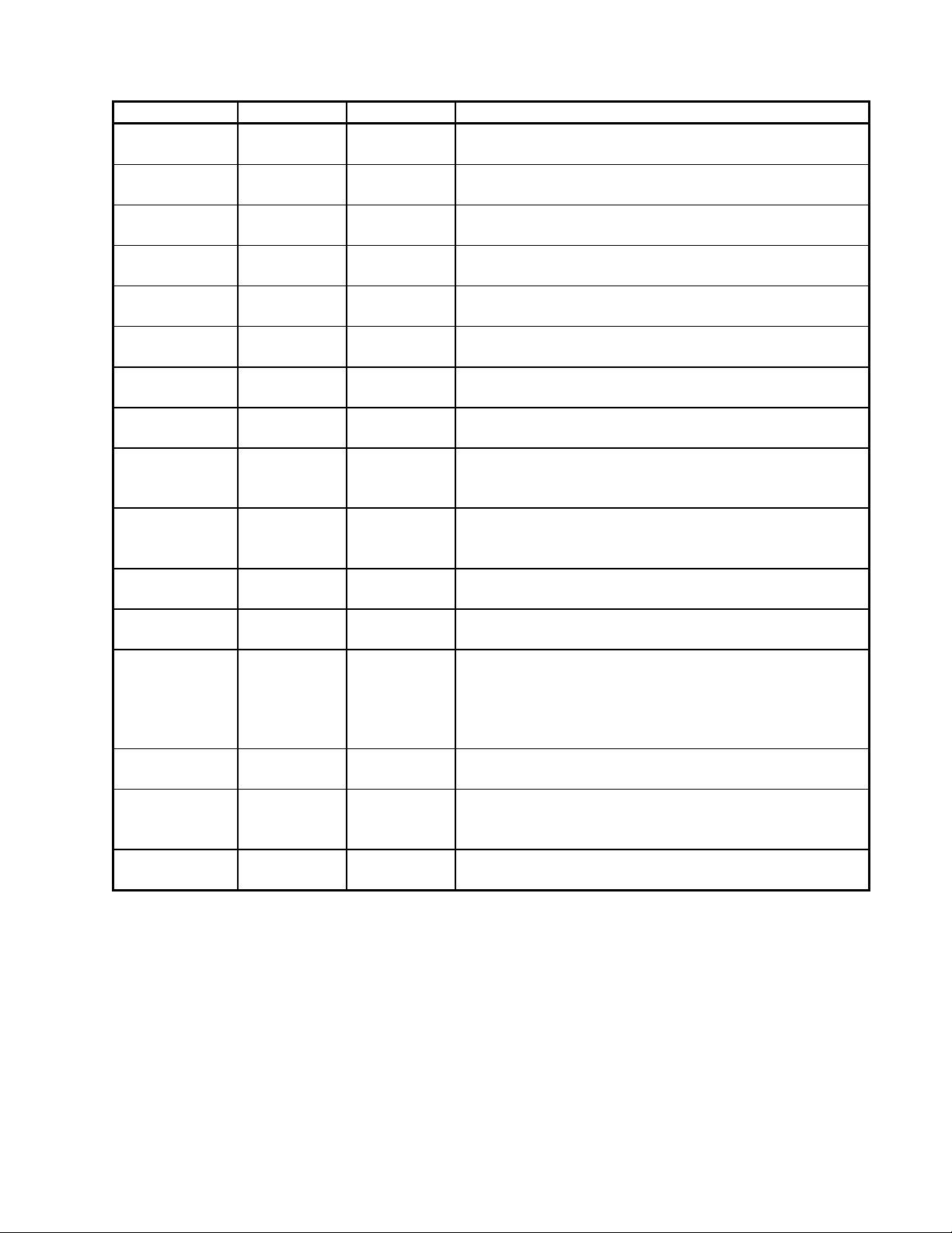
Nominal
Figure 7. Nominal Bass Configuration, 2 Bass Modules
14
Page 15
THEORY OF OPERATION
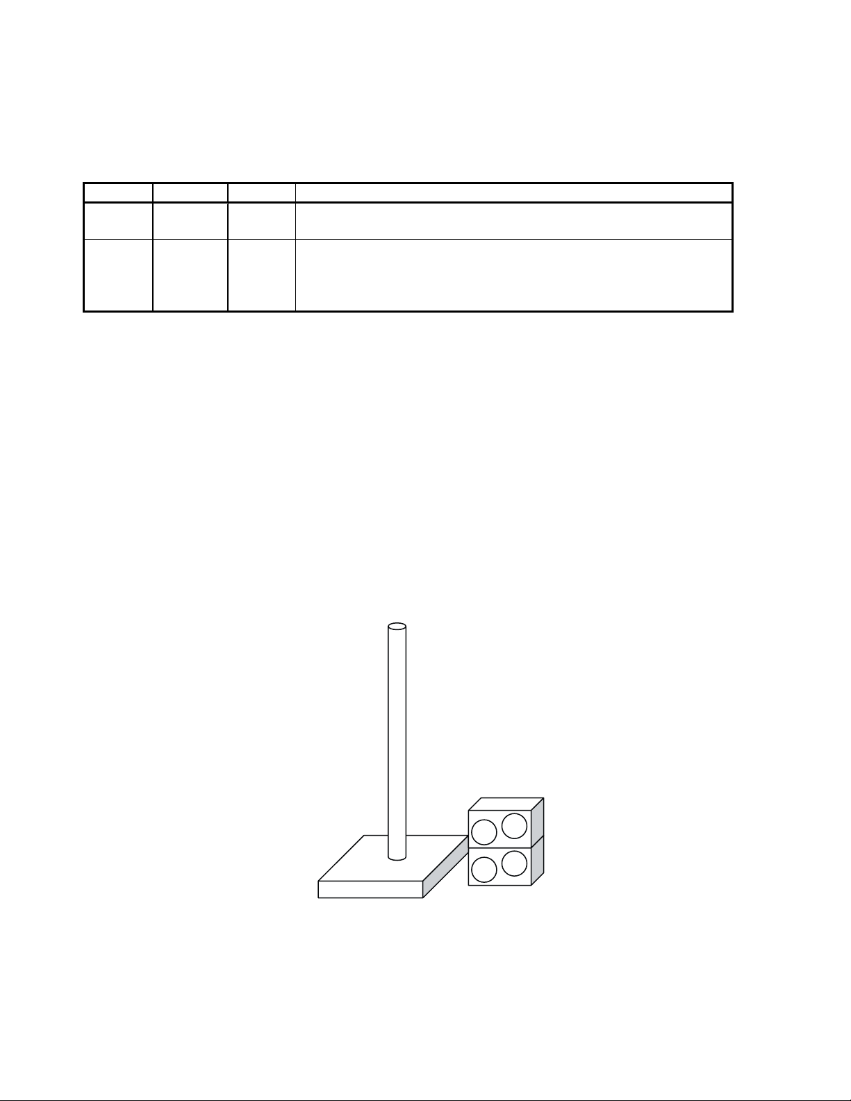
Light Bass
Figure 8. Light Bass configuration
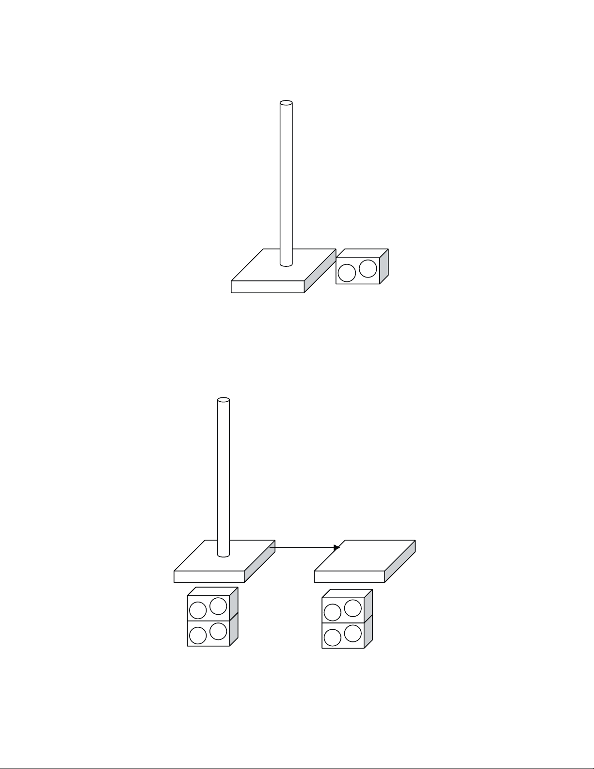
External Power Stand
External Power Stand
With 2 Bass Modules
With 2 Bass Modules
Bass
Bass
Send
Send
All Amps
All Amps
In
In
Figure 9. External power stand, total of 4 bass modules
15
Page 16

THEORY OF OPERATION
External Power Stand
With 6 Bass Modules
Bass
Send
Figure 10. “Heavy” Bass, total of 8 bass modules
Ideally, at low levels all bass configurations should produce the same spectral balance, and the
main difference between the “light” system and the “heavy” system should be that the “heavy”
system can produce 18dB more SPL before the limiter kicks in.
If we label the system with 2 bass modules “nominal” and assign it a relative level of 0dB, we
would have to apply the following gains to achieve equal spectral balance.
All Amps
In
Total number
of bass modules
2 0 dB 0 dB
1 +6dB +6dB
4 - 6 dB -6 dB
6 -9.5 dB -6 dB
8 -12 dB -6 dB
Table 4. Ideal and actual bass EQ gains
Unfortunately, the first power stand (which provides the EQ and gain for all bass signals) has no
way of knowing how many bass modules are connected to the second external power stand and
currently there is no user interface that would allow the user to specify that in any way. Therefore, we have chosen to implement a constant drop of -6 dB whenever something is connected
to the bass send output. This will work perfectly for the first 3 cases in Table 5, but lead to excessive bass in the last 2 cases. The amount of excess bass is 3.5dB for 6 bass modules and 6dB
for 8 bass modules. Given the fact that the user probably wants lot of bass in these configurations, the excess bass is deemed acceptable.
Ideal EQ Gain Actual EQ Gain Comments
16
Page 17

THEORY OF OPERATION
EQ
1.3.2 Implementation
The power stands detects:
a) The number of bass modules B1 connected to “Amp3 out”. This is done by measuring the
impedance between pins 2+ and 2- of the “Amp 3 out” connector. The B1 bass module has a
10k ohm resistor between those to pins.
b) The insertion of a 1/4" jack into the “Bass Line Out”. A normalling connection of this jack is
connected directly to a flag pin on the DSP.
Depending on these detections, the PS1 will change system EQ and limiter settings. This information is collected by the DSP and determines EQ and limiter settings through a lookup table:
Number
of Bass
Modules
0 infinity No 0 0 No bass module:
1 10k ohm No 1 1 L1: crossover at 180 Hz
2 5k ohm No 2 1 L1: crossover at 180 Hz
0 Infinity Yes 3 2 This mode is for use with external
1 10k ohm Yes 4 1 Undefined state, user may be using
2 5k ohm Yes 5 1 This is the nominal case with an
?? 0 Either 6 0 Debug Mode: all EQ and limiters
Impedance,
Amp3
2+ - 2-
Bass
Send
connected
Bass
EQ
Comment
LA
L1: Select highpass at 110Hz
B1: 40-110Hz flat bandpass
B1: “nominal EQ” +6 dB
B1: “nominal EQ”
powered sub.
L1: crossover at 180 Hz
B1: flat 40Hz to 180Hz
an external 3rd party device with a
single B1
L1: crossover at 180 Hz
B1: “nominal EQ”
additional external power stand
connected
L1: crossover at 180 Hz
B1: “nominal EQ” -6 dB
are by-passed.
Table 5. EQ lookup table for all operational modes
1.3.3 Debug Mode
Debug mode is entered when a resistance of 1k ohm or less is detected between pins 2- and 2+
at the “Amp3 Out” connector. In debug mode, all system EQ’s are set to “flat” and the internal
limiters are bypassed. Most measurements should be done in debug mode.
A simple way to switch between the different modes is to create a “dummy” cable that brings out
pins 2- and 2+ to a banana plug. The modes can be switched by applying different numbers of
10k ohm resistors or a short between the leads of the banana plug. Pins 1+ and 1- of the
“dummy” cable can still be routed to a Speakon
®
connector to attach B1 bass modules.
17
Page 18

THEORY OF OPERATION
1.4 Power Supply Electronics
The PS1 is powered by a total of four distinct switch-mode power supplies. All of these are fed
approximately 340VDC from the single input filter PC Board which contains numerous EMI
filtering components, in addition to a bridge rectifier and storage capacitors C607 and C608
[FCC Filter PCB sheet1, C4]. NTC thermistors TH601 & TH602 [C2] provide added resistance
at start-up to lower the inrush current.
Three identical board assemblies provide a separate ±27VDC to each of the power amplifier
channels. These are regulated with a transformer-coupled, two-FET forward converter topology.
Isolation is provided by the main transformer T503 [27 Volt Power Supply PCB sheet 1, C4], and
by the gate-drive transformer T502 [A3]. In addition to the internal over-current protection provided in the controller IC, there is an external input which shuts down an individual channel’s
power supply if a fault is sensed by the respective amplifier channel.
The fourth SMPS PC Board assembly, known as the Auxiliary Power Supply, provides all of the
other low-voltage, low-power DC voltages required by the remainder of the PS1’s electronics.
These are ±15V, +24V, +5V and +3.3V. They are regulated with a direct-coupled, single-FET
flyback converter topology. Isolation is provided by the main flyback transformer T601 [Auxiliary
Power Supply PCB sheet 1, C2], and by two opto-couplers IC602 and IC606 [B3]. Feedback for
regulation is derived from the 3.3V digital and +15V analog outputs. Regulation of the other
outputs depends on close coupling of transformer T601’s secondaries.
The +24V output is used to power the cooling fans [sheet 2, D3], which are in turn driven in
proportion to the output signal level. +24V is also used to provide phantom power for the microphone inputs. +5 and +3.3V outputs are used primarily to power the DSP, A/D & D/A converters,
microcontrollers, remote control communications, etc. The ±15V outputs power the numerous
OpAmps and other analog circuitry.
1.5 Audio Signal Path
1.5.1 General Notes - All Analog Inputs and Outputs
All user-accessible inputs and outputs are protected from RF interference (EMI) and static
discharge (ESD) by rail-rail diode clamps, spark gaps, and RC filtering. Extensive filtering is also
applied to speaker, power and Remote connections to prevent transmitted or received interference. All Analog inputs and outputs are configured as non-inverting, i.e. all ins and outs are in
phase with each other. Standard polarity conventions apply; XLR connectors are wired pin 2
pos, pin 3 neg.
The remote control does not carry any analog signals, rather it transmits MIDI code bidirectionally over an 8-conductor MIDI cable.
1.5.2 Preamplifier
The INA163 low-noise instrumentation amplifier forms the core of the PreAmp section. Gain of
both the Mic and Line inputs is determined by the impedance between the RG pins 12 and 3,
which consists of Trim control VR101/102 [input panel PCB sheet 1, A3 and C3] and R133/
R168. The balanced microphone input is protected from EMI, ESD and DC voltages (including
phantom power) by a rail-rail diode clamp, spark gaps, and numerous R’s and C’s. The unbalanced Line input is buffered by FET-input OpAmp U101A [D2] / U103A [B2] to maintain the
very high input impedance which is often required by instruments with magnetic pickups. R105
and 107 attenuate the Line input to an appropriate level as it is fed into the INA163.
18
Page 19

THEORY OF OPERATION
Input “combo-jacks” J101 and J102 [C1, A1] are configured so that outputs from buffer amps
U101A & U103A are shorted to ground when a ¼” plug is not inserted into J101 or J102 – this
eliminates the OpAmps’s noise contribution when the Mic input is in use, or when the channel is
not being used. U101B and U103B provide “DC servo” feedback to the INA163’s to effectively
null out any DC that would appear on their outputs.
Phantom Power
Condenser microphones are popular for many applications; they require a balanced external
power source applied equally to pins 2 & 3 of the XLR-type microphone connector. In addition
to an on/off switch and pilot LED, additional circuitry is provided to enable the +24VDC Phantom
power supplies to ramp up and down at a relatively slow rate, thereby preventing turn-on and
turn-off pops and clicks.
1.5.3 Line Out
The Ch1 and Ch2 XLR balanced Line Outputs are driven by OpAmps U106 and U107 [A6, C6].
These stages translate the internal PreAmp output signal to a differential balanced output.
1.5.4 Digitally Controlled Analog Volume
Ch1 and Ch2 Volume controls are implemented though a Toshiba TCA9459F chip, U302 [microprocessor PCB sheet 1, C3]. This chip contains a resistor ladder and a series of analog switches
that attenuate the input according to serial commands from the microcontroller. Attenuation of
0dB to -89dB (plus “off”) is available in steps of 1dB, but the PS1’s software contains a look-up
table to access a subset of these steps. This optimizes the feel of the control over the range of
0 to -40dB. The range is restricted to prevent the user from inadvertently turning the signal path
completely off.
1.5.5 Channel Insert
J105 and J106 [input panel PCB sheet 1, B5] are stereo ¼” jacks configured with the output
(“Send”) connected to the Ring terminal, and the input (“Return”) connected to the tip. Usually,
this would be used with a special “insert Y-cord” to route the Ch1 or Ch2 signal to an external
effects device such as a reverb, chorus, etc. If a 2-conductor (mono) ¼” plug is fully inserted,
the signal will be routed directly into the A/D converter, bypassing all of Ch1 or Ch2’s PreAmp
and Channel Volume control circuitry.
1.5.6 Channel 3 & 4 Inputs
The input signals are received through J107 [C8] /J108 [A8]. These are unbalanced 1/4" jacks
which short the input to ground if nothing is inserted. The signal is attenuated by VR103/VR104,
AC coupled, buffered and amplified through U108A/U108B and then routed to the A/D converter
U385 [DSP PCB sheet 1, D5] (Crystal CS5361). Because there is no active circuitry between
the inputs and the level controls, judicious setting of the controls can allow Ch3 and Ch4 to
accept very high input levels.
1.5.7 Analog to Digital Converters (Analog)
The PS1 has two stereo A/D converters Crystal CS5361. U386 [C5] receives channels 1 and 2,
U385 receives channels 3 and 4. Each channel signal is received on the DSP board through
CN104 [B1]. Each signal is AC-coupled, buffered and balanced through op-amp pairs (U381A/B
– U384A/B). All eight resulting signals are clipped with diode pairs and routed to the A/D chips.
19
Page 20

THEORY OF OPERATION
1.5.8 Digital to Analog Converter (Analog)
The stereo D/A converter U387 [B5] is of type Crystal CS4392. It has two symmetrical outputs
that get turned into an unbalanced signal through difference amplifier U388A [D7] /U388B [B7].
These OpAmp sections also form additional 2-pole low-pass filters that help remove out-of-band
components from the audio output. The “left” output contains the signal for L1 Cylindrical Radiator™ loudspeaker and the “right” output contains the signal for the B1 bass module. These get
routed through CN115 back to the input panel board.
1.5.9 Power Amp Inputs and Bass Line Out
J113 Bass Line Out jack [input panel PCB sheet 2, D3] provides a TRS balanced & buffered
version of the “right” / bass output from the D/A. This is used primarily for driving another PS1,
which in turn powers 2-6 additional B1 Bass Modules (see 1.3.1 figure 10, “Heavy Bass” configuration). Both + and – signals are resistor-isolated so that either balanced or unbalanced ¼”
phone connections may be used.
An “All-Amps-In” connector J112 [C1] allows a single input to drive all 3 amplifiers equally. This
will most often be driven from the Bass Line Out of another PS1 as mentioned above. J112’s
switching configuration allows both high and low frequency channels to drive the appropriate
channels when the All-Amps-In connector isn’t in use, and allows the addition of a buffer U112A
[B3] to maintain a greater than 10k ohm input impedance when the connector is used.
J114, 115 and 116 [C/D4] allow each power amplifier to be driven separately; this would generally only be used in special applications where a single “slave” PS1 is used to add bass from two
different “master” PS1’s.
1.5.10 Power Amplifiers
Note: Refer to the Digital Amplifier PCB schematic sheets for the following information.
Each of the PS1’s 3 amplifier channels is implemented with a 2-chip Class-D solution from
Philips. The three identical channels are located on one PCB assembly, but they are kept
independent by separate power supply, I/O and control connections. Each TDA8929T PWM
controller (U803, U806 and U809) [sheets 2, 3 and 4, C4] interfaces directly to two TDA8927J
(U801, U802, U804, U805, U807 and U808) power output stages. Normally, only one 8927 is
used, but in our case, the two halves of each 8927 are operated in parallel (doubling the available output current), and the two paralleled chips are driven out of phase to achieve the bridged
output configuration. Current sharing between the two halves of the 8927 chips is achieved by a
separate output LC filter for each section. The direct interface allows excess current in any one
of the output stages to immediately shut down all drive signals from the 8929 controller chip.
Numerous bypassing and filtering elements are added to the power amplifier to mitigate the
effects of the high currents at the nominal switching frequency of about 300 kHz.
In addition to the overcurrent shutdown path (amp shuts down power supply), there is other
outboard circuitry added to shut down an amplifier channel if the corresponding power supply
voltage is too low (usually due to extreme overdrive), and also another path to shut down a
channel’s power amp and power supply if excess DC voltage appears at the output.
20
Page 21

THEORY OF OPERATION
1.6 Digital Audio
1.6.1 Overview
The PS1 contains a DSP Analog Devices 21065L, U461 [DSP PCB sheet 3, B4] and a one time
programmable micro-controller U342 [microprocessor PCB sheet 2, C3]. The microcontroller
essentially interfaces to all peripherals and communicates the information from/to the peripherals to the DSP which contains most of the intelligence of the system. In addition the
microcontroller acts as a watchdog for the DSP, i.e. it will reset the DSP if the DSP chip hangs
up.
1.6.2 Audio Clocking
The audio signal processing is done at 48 kHz which gets created by an internal 12.288 MHz
(= 256*48kHz) oscillator. XTAL431 [DSP PCB sheet 2, B3] and distributed through U434 [B5].
The PS1 can receive SPDIF through the DATA In connector, but this data is received asynchronously to the actual audio data. This is different from most other Bose
master clock is derived from a digital input (if it exists).
®
products, where the
Digital audio is transported through an I
2
S interface (Serial data, Bit clock, Left/Right clock).
U386 [DSP PCB sheet 1, C5] (channel 1/2 A/D) generates the bit clock and the Left/Right clock.
These clocks get buffered through U433 [DSP PCB sheet 2, C5] and routed to U385 [DSP PCB
sheet 1, D4] (channel 3/4 A/D), U387 [B4] (D/A), SPORT 1 (serial port 1) of the DSP, and the
SPDIF transmitter U435 [DSP PCB sheet 2, B7] (Crystal 8046).
1.6.3 Digital to Analog and Analog to Digital Converters (Digital)
Both A/D converters (U385/U386) and the D/A (U387) are hardware configured. U386 is configured as a master and U385 as a slave. The DSP can reset the A/D through FLAG3 and the D/A
through FLAG2. The data is received by the DSP on SPORT1 (serial port 1) channel A (U385)
and channel B (U386). The DSP transmits the audio data again on SPORT1 (serial port 1)
channel A (to the D/A, U387) and channel B (SPDIF transmitter, U435).
1.6.4 SPDIF Interface
The SPDIF output provides the unprocessed audio received from channel 1 and 2. It is basically
a digital copy of the input signals to U386. The audio is sent by the DSP through channel B on
SPORT1 in I2S mode and received by U435, a Crystal 8046 SPDIF transmitter. U435 can be
reset by the DSP through FLAG1. U435 generates proper SPDIF signals and these get routed
through a transformer T431, through CN113 back to the Data Out connector on the panel board.
The “Data In” SPDIF input is NOT designed to receive actual audio, but to receive data that is
disguised as a SPDIF bit stream. The SPDIF input is clocked independent from the rest of the
system. The signal is received on the “Data In” connector on the panel board and routed through
CN112 to the DSP board and received by Crystal 8416 SPDIF receiver (U431), which performs
clock and data recovery. The data is transferred through an I2S interface to the DSP and received through SPORT0 on channel A. The DSP evaluates the data asynchronously. The DSP
can reset U431 through FLAG0 and can monitor the whether the U431 has valid audio through
FLAG8.
21
Page 22

THEORY OF OPERATION
1.7 Digital Signal Processor
1.7.1 Architecture
The DSP is an Analog Devices ADSP21065L processor. It boots from an EEPROM
SST20LE020, U462 [DSP PCB sheet 3, C7]. U462 accessed through boot memory space and
through external memory space 3. Either BMS or MS3 on the DSP will chip enable U462 and
then a standard write/read enable interface is used to address U462. The DSP is reset by the
microcontroller through RESET. Chip clock is locally provided through XTAL461 [A2] at 30 MHz
resulting in a 60 MHz internal clock speed.
1.7.2 Interface to Microcontroller
Besides the audio peripherals described in the previous section, the DSP only interface to the
microcontroller. The DSP receives data on FLAG4 (P10 on the micro), transmits data on FLAG5
(P11 on the micro) and FLAG11/P12 provide clocking. RESET/P13 provides the reset for the
DSP and the watchdog functionality. The interface signals are routed through CN341 [microprocessor PCB sheet 2, C8] between DSP and microcontroller board.
1.7.3 Internal LED
The DSP displays a “heartbeat” signal to an internal LED on the DSP board though FLAG10.
1.8 Microcontroller
1.8.1 Overview
The microcontroller is clocked by X341 [D3] (12 MHz) and provides interfaces between nearly all
peripherals.
Pins Interface Type
P24-P27 Preset switch CH 1, single digit static
P20-P23 Preset switch CH 2, tens digit static
P4-P7 Preset switch CH 1, sing le digit static
P0-P3 Preset switch CH 1, t ens digit static
P10-P13 DSP Interface SPI
P14-P15 Remote Modified MIDI
P37/ADC7 B1 detection from AMP3 Out Analog
P34 Power Amp Protection/Trouble Static
P33 Power Supply Protection Static
P30-P32 Interface to volume control chip I2C
P44-P45 Power LED (red/green) static
P43 Bass Sent detection from “Bass Line Out” static
Table 6. Peripheral pins on the microcontroller
1.8.2 Interface to Remote
Relay of DSP information to the Remote. The DSP in the power stand needs to transfer the clip
state, channel volume data (cause the table for channel volume in the DSP), system working
status to MCU. The communication adopts software simulation UART, with two I/O pins as RX
and TX. Communication rate is 4800bps, add start bit and stop, so every sending byte has 10
bits. Data is send according to frame format: frame head | every data | check sum. DSP will
transfer a frame every 100ms, and every sending will take about 15ms.
22
Page 23

THEORY OF OPERATION
The MCU needs to transfer the clip state information to the remote control. The communication
protocol adopts hardware UART. The communication rate is 9600bps, Data is sent according to
MIDI protocol: MIDI channel number | MIDI parameter type | MIDI parameter value. DSP will
transfer a frame data every 100ms, and every sending will take about 3.5ms.
Relay of Remote information to the Power Stand DSP. The remote needs to transfer the
Ch1EQHi, Ch2EQHi, Ch1EQMi, Ch2EQMi, Ch1EQLo, Ch2EQLo, Ch1Volume, Ch1Volume, and
MasterVolume information to the power stand MCU PCB. The communication adopts hardware
UART. The communication rate is 9600bps, Data is sent according to the MIDI protocol: MIDI
channel number | MIDI parameter type | MIDI parameter value. DSP will transfer a frame data
every 100ms, and every sending will take about 30ms.
The power stand MCU PCB needs to transfer the Ch1EQHi, Ch2EQHi, Ch1EQMi, Ch2EQMi,
Ch1EQLo, Ch2EQLo, Ch1Volume, Ch1Volume, MasterVolume, Ch1Preset, Ch2Preset,
BassChk, and CheckSum information to the DSP. The communication adopts software simulation UART, with two I/O pins as RX and TX. Communication rate is 4800bps, add start bit and
stop, so every sending byte has 10 bits. Data is sent according to frame format: every data |
check sum. DSP will transfer a frame every 100ms, and every sending will take about 30ms.
1.9 Software and User Interface
The Bose
which is mostly implemented in software. In this chapter we describe how most of the functions
are implemented.
1.9.1 Gain Staging
Gain staging is the process of properly adjusting the gain of the system. The goal is to set the
gains as high as possible (to optimized signal/noise) without overdriving or clipping any electronic components. In contrast to home-audio products, musical instrument and microphones
have a large variation of output gains and gain staging is typically required.
On Channel 1 and 2, the user needs to set the trim control on the power stand so that the
overload LED just turns red for the loudest anticipated input signals and then back up a little.
This is done purely in analog and the goal is to not overload the preamplifier.
Next the user should adjust the channel volume on the remote so that the LED on the remote
does not turn red. The LEDs are calibrated so that for sine wave input, nothing connected to the
insert loop, and the channel volume at the 12 o’clock setting both LEDs turn red at the same
level.
1.9.2 Channel Volume
The microcontroller polls the remote in regular intervals, about 10 times per second. The
microcontroller then maps the settings to a range from -40 to 0 dB and programs the volume
control chip U302 through its digital control interface. The volume control should span a range of
40 dB with a linear (in dB) range from -30dB to -10dB from all the way down to 12 o’clock and a
range from -10dB to 0dB for 12 o’clock to “all the way up” setting.
®
Personalized Amplification System™ family of products has a simple user interface
1.9.3 Tone Controls
The microcontroller polls the remote in regular intervals. The microcontroller transfers the tone
control settings to the DSP which implements them for each channel as shown in Figure 11.
23
Page 24

THEORY OF OPERATION
PS1 tone controls
PS1 tone controls
PS1 tone controls
15
15
15
10
10
10
5
5
5
0
0
0
dBV/V
dBV/V
dBV/V
-5
-5
-5
-10
-10
-10
-15
-15
-15
-20
-20
-20
2
2
2
10
10
10
Frequency (hertz)
Frequency (hertz)
Frequency (hertz)
3
3
3
10
10
10
Figure 11. PS1 Tone Control Range
4
4
4
10
10
10
1.9.4 Master Volume
The microcontroller polls the remote in regular intervals. The microcontroller transfers the master volume setting to the DSP which implements them for each channel as shown in Figure 5.
The master volume should mute the system if all the way down and then ramp up to a nominal
value of 0dB at the center position. From the center position to “all the way up” the master
volume increases the gain by another 12 dB.
1.9.5 Preset Switching
The microcontroller polls the preset switches on the panel board in regular intervals and transfers the values to the DSP. If the DSP detects a change in the setting, it will mute the respective
channel, load the new filter coefficients according to a lookup table, clear the filter state coefficients and un-mute the channel again. This takes about 1 to 2 seconds.
Presets are basically a spectral correction (like an EQ) to the signal. Preset “00” corresponds to
flat. An easy preset to check is 97 which is a 1 kHz band pass filter (“telephone” sound). In
addition to the spectral EQ, there is also a noise gate available.
1.9.6 Bass Line Out Detection
The microcontroller polls the normalling switch on the Bass Line Out connector in regular intervals and transfers its state to the DSP. If the DSP detects a change in the state, it will mute the
entire power stand, latch in new system EQ coefficients through a lookup table, clear the system
EQ state variables and un-mute the power stand. This takes about 1 to 2 seconds.
1.9.7 Bass Module Detection
The microcontroller measures the resistance between the pins 2- and 2+ of the Amp3 Out
connector in regular intervals and transfers the setting to the DSP. If the DSP detects a big
enough change in the setting, it will mute the entire power stand, latch in new system EQ coefficients through a lookup table, clear the system EQ state variables and un-mute the power stand.
This takes about 1 to 2 seconds.
24
Page 25

THEORY OF OPERATION
1.10 Power Cycling
1.10.1 Power Up
When power is first applied, 110V AC is applied to the primary side of the transformer1, and at
the secondary side of the transformer1 will charge up +24V, +15V, -15V, +5V, +3.3V. And after 7
ms, they become stable almost at the same time. But +27V/-27 for amplification is late other
voltage about 6ms.
Power-up time complies with the following sequence:
• With +3.3V, +5V, +15V, -15V, the ADC/DAC/buffer circuit/MCU starts to work
• After power on 15ms, amplifier starts to work
• DSP uses RC reset. After about 300ms, DSP starts to work
• After DSP starts to work, DSP first resets ADC, then digital receiver, and then digital
transmitter, then DAC. Every reset time is 100ms
• After power on about 700ms, latest DAC’s reset is completed
At this point, normal signal processing commences. But in order to get correct remote value
& preset number & number of bass, DSP mutes input signal, and it should no more than
1.5 seconds from the time power is applied until the time audio appears at the speaker output.
1.10.2 Power Down
Upon power-down the muting circuitry comprised of Q810, Q811, DZ805, R895 and C959
[digital amplifier PCB sheet 3, D2] is responsible to mute any noise coming out from the output
of U387 CS4392 Digital-to-Analog converter.
The principle is to detect the voltage VDDA falling below 22 volts. This will cut off the DZ805
Zener diode and Q810 NPN transistor. This in turn will turn on Q811 NPN transistor and pull the
voltage of U806 pin 6 from 5 volt to 0 volt. This action will shut down the class-D amplifier U804
and U805 so that any noise will be muted.
1.11 Software and Preset / EQ Updates
The PS1 software and Preset /EQ files can be updated via the Data In jack J109 [input panel
PCB sheet 2, A1] on the PS1 input panel. Refer to the software update procedures in the appendix of this troubleshooting guide.
2. Remote R1
The Remote is a wired remote, connected to the PS1 power stand via an 8 pin MIDI cable.
There are a total of nine knobs on the remote, their functions is as follow:
• Knob for tone regulation
• Knob for channel volume control
• Knob for master volume control
• Two LEDs to indicate clip
The communication between the remote control and the PS1 power stand uses the MIDI protocol, operating at 9600baud. The remote control is non-repairable.
25
Page 26

THEORY OF OPERATION
3. Cylindrical Radiator™ Loudspeaker L1
The L1 Cylindrical Radiator speaker array consists of two sections, an upper and lower section,
with 12 drivers each for a total of 24 drivers. The lower array section plugs directly into the cavity
in the center of the PS1 power stand. Electrical connections are made via Molex connectors in
the PS1 and the bottom of the lower array section. The upper section of the line array plugs
directly into the top of the bottom section, aligned by a bayonet pin. Electrical connection is
made by another Molex connector to the top of the lower array section. The result is that there
are no cables needed to connect the line array sections to the PS1 power stand.
There is no crossover or protection circuitry in either section of the line array. All protection and
EQ is performed in the PS1 power stand. The drivers of both sections are replaceable, as are
the grilles and the Bose
4. Bass Module B1
The B1 bass module is a dedicated passive unit that houses two 5 1/4” drivers. The input is via
two 4-pole Neutrik® Speakon® connectors on the rear panel. Both of these inputs are paralleled,
allowing you to jumper multiple bass modules together. There are no crossover or protection
ciricuit components located on the input panel. All EQ and protection is performed in the PS1
power stand.
®
logo.
Pins 1+ and 1- of the input connector are used to apply the input signal to the bass module. Pins
2+ and 2- are connected to a 10k ohm resistor on the bass module rear panel PCB. This allows
the PS1 power stand to detect how many bass modules are connected to it from the Bass/Amp3
Out connector.
If the PS1 sees a 10k resistance, it knows that there is only one bass module connected and
adjusts the output level and EQ accordingly. If the PS1 sees 5k ohm resistance, it knows that
there are 2 bass modules connected, and again, adjusts the output level and EQ accordingly.
If the PS1 sees an infinite resistance, it knows that there is no bass module connected and
adjusts accordingly.
The woofers in the bass module are replaceable. The input panel, grille and Bose logo are also
replaceable.
26
Page 27

TEST PROCEDURES
PS1 Power Stand Tests
Equipment Required
• dB Meter
• Digital Multi-meter
• Audio Signal Generator
• Distortion Meter
• 3 - 4 Ohm, 250 Watt Load Resistors
• Test cables, see Appendix
Overall PS1 System Tests
Notes:
1. Connect 4 Ohm load resistors to the
channel 1, 2 and 3 outputs on the PS1
power stand using the test cables described
in the appendix of this troubleshooting guide.
2. Do not connect the R1 remote control for
the following tests. This has the same effect
as setting all of the controls on the remote to
the midpoint.
3. On the front panel of the PS1, set the
Channel 1 and Channel 2 Preset Select
switches to 00. This will put the PS1 into
debug mode for the following tests. In this
mode the crossover, the compressor and the
EQ are disabled. The DSP will pass a flat
response. The level controls and the clip
indicators still operate in this mode.
1.3 Using a balanced XLR male input cable,
apply a 1 kHz, -30dBV signal to the channel
1 input.
1.4 Reference a dB meter to the input level.
Measure the gain output at the Amp 1 OUT
jack. It should be +48.5 dB
1.5 Move the shorting plug from the Amp 2
IN jack to the Amp 1 IN jack and repeat
steps 1.1 to 1.4 for the channel 2 Mic input.
2. Channel 1 and 2 Mic Input Frequency
Reponse and Distortion Tests
2.1 Place a 1/4” mono shorting plug into the
Amp 2 IN and Amp 3 IN jacks on the right
hand side of the input/output panel. This will
disable the channel 2 and 3 amplifiers while
testing the channel 1 amplifier.
2.2 On the left hand side of the input/output
panel, set the channel 1 Mic Trim control to
the 6 setting. Ensure that the Line In +20dB
gain and the Phantom Power push buttons
are not pushed in.
2.3 Using a balanced XLR male input cable,
apply a 1 kHz, -30dBV signal to the channel
1 input.
+ 3dB.
1. Channel 1 and 2 Mic Input Gain Tests
1.1 Place a 1/4” mono shorting plug into the
Amp 2 IN and Amp 3 IN jacks on the right
hand side of the input/output panel. This will
disable the channel 2 and 3 amplifiers while
testing the channel 1 amplifier.
1.2 On the left hand side of the input/output
panel, set the channel 1 Mic Trim control to
the 6 setting. Ensure that the Line In +20dB
gain and the Phantom Power push buttons
are not pushed in.
2.4 Use an 80kHz low-pass filter on your
measuring equipment. Reference a dB meter
to the input level. Measure the frequency
response at the Amp 1 OUT jack. It should
be 0dB + 3dB from 30Hz to 15kHz.
2.5 Measure the Total Harmonic Distortion
(THD) level at the Amp 1 OUT jack. It should
be 0.25% max at 1kHz and 1.5% max at
15kHz.
2.6 Move the shorting plug from the Amp 2
IN jack to the Amp 1 IN jack and repeat
steps 2.1 to 2.5 for the channel 2 Mic input.
27
Page 28

TEST PROCEDURES
3. Channel 1 and 2 Mic Input Signal to
Noise Ratio (Dynamic Range) Tests
3.1 Place a 1/4” mono shorting plug into the
Amp 2 IN and Amp 3 IN jacks on the right
hand side of the input/output panel. This will
disable the channel 2 and 3 amplifiers while
testing the channel 1 amplifier.
3.2 On the left hand side of the input/output
panel, set the channel 1 Mic Trim control to
the 6 setting. Ensure that the Line In +20dB
gain and the Phantom Power push buttons
are not pushed in.
3.3 Using a balanced XLR male input cable,
apply a 1 kHz, -30dBV signal to the channel
1 input.
3.4 Reference a dB meter to the output level
at the Amp 1 OUT jack. Remove the input
signal and measure the A-Weighted output
level. It should be -80dB minimum.
3.5 Move the shorting plug from the Amp 2
IN jack to the Amp 1 IN jack and repeat
steps 3.1 to 3.4 for the channel 2 Mic input.
4. Channel 1 and 2 Line Input Gain Tests
4.1 Place a 1/4” mono shorting plug into the
Amp 2 IN and Amp 3 IN jacks on the right
hand side of the input/output panel. This will
disable the channel 2 and 3 amplifiers while
testing the channel 1 amplifier.
4.2 On the left hand side of the input/output
panel, set the channel 1 Mic Trim control to
the 6 setting. Ensure that the Line In +20dB
gain and the Phantom Power push buttons
are not pushed in.
4.4 Reference a dB meter to the input level.
Measure the gain output at the Amp 1 OUT
jack. It should be +28.5 dB + 4dB.
4.5 Move the shorting plug from the Amp 2
IN jack to the Amp 1 IN jack and repeat
steps 4.1 to 4.4 for the channel 2 Line input.
5. Channel 1 and 2 Line Input Frequency
Reponse and Distortion Tests
5.1 Place a 1/4” mono shorting plug into the
Amp 2 IN and Amp 3 IN jacks on the right
hand side of the input/output panel. This will
disable the channel 2 and 3 amplifiers while
testing the channel 1 amplifier.
5.2 On the left hand side of the input/output
panel, set the channel 1 Mic Trim control to
the 6 setting. Ensure that the Line In +20dB
gain and the Phantom Power push buttons
are not pushed in.
5.3 Using an unbalanced 1/4” phono jack
input cable, apply a 1 kHz, -10dBV signal to
the channel 1 input.
5.4 Use an 80kHz low-pass filter on your
measuring equipment. Reference a dB
meter to the input level. Measure the frequency response at the Amp 1 OUT jack.
It should be 0dB + 3dB from 30Hz to 15kHz.
5.5 Measure the Total Harmonic Distortion
(THD) level at the Amp 1 OUT jack. It should
be 0.25% max at 1kHz and 1.5% max at
15kHz.
5.6 Move the shorting plug from the Amp 2
IN jack to the Amp 1 IN jack and repeat
steps 2.1 to 2.5 for the channel 2 Line input.
4.3 Using an unbalanced 1/4” phono jack
input cable, apply a 1 kHz, -10dBV signal to
the channel 1 input.
28
Page 29

TEST PROCEDURES
6. Channel 1 and 2 Line Input Signal to
Noise Ratio (Dynamic Range) Tests
6.1 Place a 1/4” mono shorting plug into the
Amp 2 IN and Amp 3 IN jacks on the right
hand side of the input/output panel. This will
disable the channel 2 and 3 amplifiers while
testing the channel 1 amplifier.
6.2 On the left hand side of the input/output
panel, set the channel 1 Mic Trim control to
the 6 setting. Ensure that the Line In +20dB
gain and the Phantom Power push buttons
are not pushed in.
6.3 Using an unbalanced 1/4” phono jack
input cable, apply a 1 kHz, -10dBV signal to
the channel 1 input.
6.4 Reference a dB meter to the output level
at the Amp 1 OUT jack. Remove the input
signal and measure the A-Weighted output
level. It should be -80dB minimum.
6.5 Move the shorting plug from the Amp 2
IN jack to the Amp 1 IN jack and repeat
steps 6.1 to 6.4 for the channel 2 Line input.
8. Channel 3 and 4 Line Input Frequency
Reponse and Distortion Tests
8.1 Place a 1/4” mono shorting plug into the
Amp 1 IN and Amp 2 IN jacks on the right
hand side of the input/output panel. This will
disable the channel 1 and 2 amplifiers while
testing the channel 3 amplifier.
8.2 On the left hand side of the input/output
panel, set the channel 4 Mic Trim control to
the 6 setting.
8.3 Using an unbalanced 1/4” phono jack
input cable, apply a 1 kHz, -20dBV signal to
the channel 1 input.
8.4 Use an 80kHz low-pass filter on your
measuring equipment. Reference a dB
meter to the input level. Measure the frequency response at the Amp 1 OUT jack.
It should be 0dB + 3dB from 30Hz to 15kHz.
8.5 Measure the Total Harmonic Distortion
(THD) level at the Amp 1 OUT jack. It should
be 0.25% max at 1kHz and 1.5% max at
15kHz.
7. Channel 3 and 4 Line Input Gain Tests
7.1 Place a 1/4” mono shorting plug into the
Amp 1 IN and Amp 2 IN jacks on the right
hand side of the input/output panel. This will
disable the channel 1 and 2 amplifiers while
testing the channel 3 amplifier.
7.2 On the left hand side of the input/output
panel, set the channel 3 Level control to the
6 setting.
7.3 Using an unbalanced 1/4” phono jack
input cable, apply a 1 kHz, -20dBV signal to
the channel 1 input.
7.4 Reference a dB meter to the input level.
Measure the gain output at the Bass/Amp 3
OUT jack. It should be +40.1dB
7.5 Repeat steps 7.1 to 7.4 for the channel 4
Line input.
+ 3dB.
8.6 Repeat steps 8.1 to 8.5 for the channel
4 Line input.
9. Channel 3 and 4 Line Input Signal to
Noise Ratio (Dynamic Range) Tests
9.1 Place a 1/4” mono shorting plug into the
Amp 1 IN and Amp 2 IN jacks on the right
hand side of the input/output panel. This will
disable the channel 1 and 2 amplifiers while
testing the channel 3 amplifier.
9.2 On the left hand side of the input/output
panel, set the channel 3 Level control to the
6 setting.
9.3 Using an unbalanced 1/4” phono jack
input cable, apply a 1 kHz, -10dBV signal to
the channel 1 input.
29
Page 30

TEST PROCEDURES
9.4 Reference a dB meter to the output level
at the Bass/Amp 3 OUT jack. Remove the
input signal and measure the A-Weighted
output level. It should be -80dB minimum.
9.5 Repeat steps 9.1 to 9.4 for the channel 4
Line input.
Line Array Tests
Connect the Line Array section you are
testing to an amplifier using the test cables
described in the appendix of this troubleshooting guidel.
1. Air Leak Test
1.1 Apply a 100 Hz, 10 Vrms sine wave to
the unit under test.
1.2 Listen carefully for air leaks from around
the end cap, the transducers and the grille.
Air leaks will be heard as a hissing or sputtering sound. All repairs must be hidden.
Test duration should be 5 seconds minimum.
2. Transducer Rub and Tick Test
2.1 Remove the transducer you wish to test
using the disassembly procedures in this
manual. Do not unplug the wires at the
transducer assembly terminals.
Note: To distinguish between normal suspension noise and rubs or ticks, displace the
cone slightly with your fingers. If the noise
stays the same, it is normal suspension
noise and the driver is good. Suspension
noise will not be heard with program material.
3. Transducer Phase Test
3.1 Apply a DC voltage of 10V, positive
applied to the positive terminal of the line
array test cable and GND applied to the
GND terminal.
3.2 Notice carefully that all driver cones
should move outward when the DC voltage
is applied.
3.3 Rewire any incorrectly connected transducers.
4. Line Array Sweep Test
4.1 Connect the line array section under test
to the output of an amplifier being driven by
an audio signal generator. Use the line array
test cables described in the appendix of this
troubleshooting guide.
4.2 Apply a 10Hz, 10Vrms sine wave to the
input.
2.2 Connect a signal generator directly to the
terminals of the transducer assembly under
test.
2.3 Apply a 20 Hz, 5 Vrms signal to the
transducer assembly.
2.4 Listen carefully for any extraneous
noises such as rubbing, scraping or ticking.
4.3 While listening to the output of the
system, sweep the input frequency slowly
from 20Hz to 20kHz. Test duration should be
10 seconds minimum.
4.4 Listen carefully for any extraneous
noises such as buzzing and ticking.
30
Page 31

TEST PROCEDURES
Bass Module Tests
Connect the Bass Module under test to an
amplifier using the test cables described in
the appendix of this troubleshooting guide.
1. Air Leak Test
1.1 Apply a 100 Hz, 10 Vrms sine wave to
the unit under test.
1.2 Listen carefully for air leaks from around
the end cap, the transducers and the grille.
Air leaks will be heard as a hissing or sputtering sound. All repairs must be hidden.
Test duration should be 5 seconds minimum.
2. Transducer Rub and Tick Test
2.1 Remove the transducer you wish to test
using the disassembly procedures in this
manual. Do not unplug the wires at the
transducer assembly terminals.
2.2 Connect the transducer to an amplifier
that is driven by an audio signal generator.
Connect directly to the terminals of the
transducer assembly under test.
2.3 Apply a 10 Hz, 10 Vrms signal to the
transducer assembly.
2.4 Listen carefully for any extraneous
noises such as rubbing, scraping or ticking.
Note: To distinguish between normal suspension noise and rubs or ticks, displace the
cone slightly with your fingers. If the noise
stays the same, it is normal suspension
noise and the driver is good. Suspension
noise will not be heard with program material.
3. Transducer Phase Test
3.1 Momentarily apply a DC voltage of 10V,
positive applied to the positive terminal of
the test cable and GND connected to the
GND terminal. The bass module test cable
is described in the appendix of this troubleshooting guide.
3.2 With the DC voltage applied, both of the
driver cones should move outward.
3.3 Rewire any incorrectly wired driver.
4. Bass Module Sweep Test
4.1 Connect the B1 bass module to an
amplifier that is driven by an audio signal
generator. Use the bass module test cable
described in the appendix of this service
manual.
4.2 Apply a 10Hz, 10Vrms sine wave to the
input of the bass module.
4.3 While listening to the output of the bass
module, sweep the input frequency slowly
from 10Hz to 400Hz. Test duration should be
5 seconds minimum.
4.4 Listen carefully for any extraneous
noises such as buzzing and ticking.
Note: To distinguish between normal suspension noise and rubs or ticks, displace the
cone slightly with your fingers. If the noise
stays the same, it is normal suspension
noise and the driver is good. Suspension
noise will not be heard with program material.
31
Page 32

APPENDIX
PS1 Power Stand Software Update Procedure
Required Equipment:
1- CD player with a S/PDIF digital output (do not use a Bose® Lifestyle® media center)
1- PS1 Power Stand update CD (see the instructions for creating this disc below)
1- S/PDIF video cable, part number 183200, or an audio cable with RCA connectors
1- PS1 Power Stand AC line cord, part number 273790
PS1 Power Stand Update CD Procedure:
• Go to the Bose Technical Service web page at http://intranet.bose.com/tsg (Bose internal
repair centers) or http:serviceops.bose.com (external Bose affiliated repair centers).
• Navigate to the Personal Amplification System web page. The link is located on the
Pro Products web page.
• Scroll down the Personal Amplification System web page to the PS1 Power Stand software
link. You should see two files, one to update the PS1 firmware and another file to update the
PS1 presets. Download the files to your computer’s desktop.
• Using a CD burner and your CD burner software, burn the files onto a blank CD-R or CD-RW
disc. Each file must be burned onto its own disc for the updates to work properly. Once these
discs are successfully created, label the discs with the software revisions.
Update Procedure:
• Plug the CD player into an AC mains outlet.
• Connect the S/PDIF cable to the Audio Outputs/Digital jack on the back of the CD player.
• Connect the other end of the S/PDIF cable to the DATA IN jack on the PS1 Power Stand’s
input panel. This jack is located in the middle of the panel. It’s an RCA jack with a white center.
• Connect the PS1 Power Stand’s AC line cord to AC mains. Turn on the PS1. Wait for the
power LED to light steady green.
• Turn on the CD player. Load the software update CD into the CD player. Press the PLAY CD/
DVD button on the remote control. The update process should begin.
• Wait about 5 seconds while the disc is playing. The green power LED on the PS1 Power Stand
should blink rapidly, about 10 times per second. After about 10 seconds, the LED should begin
to blink slower, about twice a second.
• The update process is complete. Repeat the above steps for the EQ preset disc. Power down
the PS1 Power Stand. Disconnect the S/PDIF cable from the DATA IN jack.
• Verify proper operation of the PS1 Power Stand using the test procedures in this troubleshoot-
ing guide before returning the unit to the customer.
Troubleshooting:
Problems with this update procedure are indicated by the PS1 Power Stand’s power LED.
Typical indicators are:
• LED stays a steady green.
• LED blinks slowly red
In either case, simply repeat the process above. Make sure you wait 5 seconds after power
up of the PS1 Power Stand before playing the update disc. Ensure all of the cables are properly
connected.
32
Page 33

APPENDIX
PS1 Power Stand Test Cables
Note: In order to be able to properly test the PS1 Power Stand, you will need to make up a few
test cables.
1. Amplifier Output Test Cable:
Parts needed:
®
1- Neutrik
NL4FX Speakon® X-Line/4 Pole connector.
4 - Dual banana jacks
2 - 10k ohm, 1/4 Watt resistors
16 or 18 AWG twisted pair wire, 6 feet
18 AWG twisted pair wire, 2 feet
This cable is used to connect the Amp 1 OUT, Amp 2 OUT or Bass/Amp3 OUT jacks to the load
resistors used in the test procedures. The connector used is a Neutrik NL4FX Speakon X-Line /
4 Pole type. This connector has 4 terminals labeled 1+, 1-, 2+ and 2-. Terminals 1+ and 1- are
used to connect to the load resistors. Use 18 or 16 AWG wire for these terminals. Use twisted
pair wires to avoid inducing noise into the cable during use.
The 2+ and 2- terminals will be used to sense the loads connected to the Speakon connector
when used with the Bass/Amp3 OUT jack. The load on this jack automatically sensed in order to
properly tailor the EQ and output level for the connection of one or two bass modules. It does
this by sensing the resistive value across terminals 2+ and 2-. The bass modules have a 10k
ohm resistor across these terminals. When only one bass module is connected, the PS1 sees
the 10k resistance and sets the EQ and output level accordingly. When two bass modules are
connected, it sees 5k and sets the EQ and output level accordingly. For the test cable, you will
use 18 AWG twisted pair wire to a dual banana jack.
It is also useful to have 3 spare banana jacks, one with a short across it and 2 with a 10k Ohm,
1/4 Watt resistor each to simulate a bass module connected to the terminals. The Amp 1 OUT
and Amp 2 OUT jacks do not sense this load.
GND
Amplifier output
to load resistor
16-18AWG twisted pair wire
1+1-
Neutrik Speakon
4 pole connector
(back shown)
2-2+
18AWG twisted pair wire
Dual banana jack
Dual banana jack
GND
Bass module
sensing output
Amplifier Output Test Cable Wiring Diagram
33
Page 34

APPENDIX
PS1 Power Stand Test Cables (continued)
2. XLR Microphone Input Test Cable
Parts needed:
1 - XLR male connector
1 - Dual banana jack
18 AWG shielded twisted pair wire, 6 feet
This cable is used to test the channel 1 and 2 microphone inputs on the PS1 Power Stand.
These input jacks are dual purpose jacks that will accept either XLR or 1/4” TRS phono jack
balanced inputs.
Connect the dual banana jack’s positive (+) connection to pin 2 of the XLR jack. Connect the
dual banana jack negative (-) connection to pin 3 of the XLR jack. Connect the cable shield to
pin 1 of the XLR jack.
3. Line Input 1/4” Phono Jack Test Cable
Parts needed:
1 - Mono 1/4” phono jack
1 - Dual banana jack
18 AWG shielded twisted pair wire, 6 feet
This cable is used to test the channel 1 and 2 line inputs on the PS1 Power Stand.
Connect the dual banana jack’s positive (+) connection to the tip connection of the 1/4” phono
jack. Connect the dual banana jack negative (-) connection to the ring connection of the 1/4”
phono jack.
4. Insert Jack Test Cable
This cable is used to test the channel 1 and 2 insert jacks on the PS1 Power Stand. When you
plug it into the channel 1 or channel 2 insert jack, you will be able to separate the sections of the
electronics. Refer to the PS1 Power Stand block diagram on page 3. The RETURN dual banana
jack will give you the output of the circuitry up to the output of the 2 channel digital volume
control. The SEND dual banana jack will allow you to input a signal to test the circuitry after the
insert jack, which is the input to the A/D
converter and DSP.
Parts needed:
1 - Tip/Ring/Sleeve (stereo) 1/4” phono jack
2 - Dual banana jacks
Shielded stereo cable, 6 feet
For each of the shielded stereo pairs of wires, connect the dual banana jack’s positive (+)
connection to the center conductor. Connect the dual banana jack’s negative (-) connection to
the shield wires. Use an Ohmmeter to determine which of the center conductors is connected to
the ring of the 1/4 inch TRS phono jack. Using a permanent black magic marker, label this dual
banana connector SEND. Determine which of the center conductors is connected to the tip of
the 1/4 inch TRS phono jack. Label this dual banana connector RETURN. The sleeve portion of
the jack is the common ground where the shields are connected.
TIP RING SLEEVE
34
Page 35

APPENDIX
123 54
678910
Molex Connector Rear View
5. L1 Line Array Test Cables
These two cables will allow you to test the upper and lower line array sections without a PS1
power stand. Use these cables for the line array test procedures in this service manual.
Lower Line Array Section Test Cable
Parts needed:
1 - 10 pin Molex male connector, Molex part
number 39-00-0039 (F)
4 - Molex crimp-on pins for above connector,
Molex part number 39-00-0039
1 - dual banana jack
12 feet of 16 or 18AWG twisted pair wire
Cut the 12 foot length of twisted pair wire in half. Strip all of the
wires back about 1/4 inch. Crimp the molex pins onto the wires. The positive (+) side of the
twisted pair wires will go into pins 3 and 8 of the Molex connector. The negative (-) side of the
twisted pair wires will go into pins 4 and 9 of the Molex connector. Connect the wires that go to
pins 3 and 8 of the Molex connector to the positive (+) side of the dual banana jack. Connect the
wires that go to pins 4 and 9 of the Molex connector to the negative (-) side of the dual banana
jack.
Upper Line Array Section Test Cable
34
Parts needed:
1 - 4 pin Molex male connector, Molex part number 39-01-2041
4 - Molex crimp-on pins for above connector, Molex part number
39-00-0041 (M)
1 - dual banana jack
12 feet of 16 or 18AWG twisted pair wire
12
Molex Connector
Rear View
Cut the 12 foot length of twisted pair wire in half. Strip all of the wires back
about 1/4 inch. Crimp the molex pins onto the wires. The positive (+) side of the twisted pair
wires will go into pins 2 and 4 of the Molex connector. The negative (-) side of the twisted pair
wires will go into pins 1 and 3 of the Molex connector. Connect the wires that go to pins 2 and 4
of the Molex connector to the positive (+) side of the dual banana jack. Connect the wires that
go to pins 1 and 3 of the Molex connector to the negative (-) side of the dual banana jack.
6. Bass Module Test Cable
Parts needed:
1 - Neutrik Speakon NL4FX connector
Bass Module Test Cable
GND
1 - dual banana jack
6 feet of 16 or 18AWG twisted pair wire
16-18AWG twisted pair wire
Strip all of the wires back about 1/4 inch.
Connect the dual banana jack’s positive (+)
connection to the 1+ connection of the
Speakon connector. Connect the dual
banana jack negative (-) connection to the
1- connection of the Speakon connector.
35
1+1-
Neutrik Speakon
4 pole connector
(back shown)
2-2+
Dual banana jack
Page 36

s
A
A12
A15
A16NCVDDWE#
APPENDIX
A17
4 3 2 1 32 31 30
5
A7
6
A6
7
A5
8
A4
A3
A2
A1
A0
DQ0
32-lead PLCC
9
10
11
12
13
Top View
14 15 16 17 18 19 20
SS
V
DQ1
DQ2
DQ3
29LE020 EEPROM Pinout Diagram
PIN D
ESCRIPTION
Symbol Pin Name Functio
A
17-A7
A
6-A0
DQ
7
CE# Chip Enable To activate the device when CE# is low.
OE# Output Enable To gate the data output buffers.
WE# Write Enable To control the Write operations.
V
DD
V
SS
NC No Connection Unconnected pins.
Row Address Inputs To provide memory addresses. Row addresses define a page for a Write cycle.
Column Address Inputs Column Addresses are toggled to load page data
-DQ0Data Input/output To output data during Read cycles and receive input data during Write cycles.
Power Supply To provide: 5.0V supply (4.5-5.5V) for SST29EE020
Ground
29
A14
28
A13
27
A8
26
A9
25
A11
24
OE#
23
A10
22
CE#
21
DQ7
DQ4
DQ5
DQ6
ns
Data is internally latched during a Write cycle.
The outputs are in tri-state when OE# or CE# is high.
3.0V supply (3.0-3.6V) for SST29LE020
2.7V supply (2.7-3.6V) for SST29VE020
1
2
-
+
3
45
1. Output1
8
2. Inverting input1
3. Non-inverting input 1
7
4. -Vcc
5. Non-inverting input 2
6
-
+
6. Inverting input 2
7. Output 2
8. +Vcc
TLO72, Dual Op-Amp
29LE020 EEPROM Pinout Table
F
UNC
TIONAL
B
LO
CK
D
IAGRAM
SuperFlash
17
- A
X-Decoder
0
Address Buffer & Latches
Memory
Y-Decoder and Page Latche
CE#
OE#
Control Logic
I/O Buffers and Data Latches
WE#
DQ7 - DQ
0
29LE020 EEPROM Block Diagram
36
Page 37

APPENDIX
A
B
Y
1
A1
2
B1
3
Y1
4
A2
5
B2
Y2
6
7
GND
Vcc
B4
A4
Y4
B3
A3
Y3
14
13
12
11
10
9
8
74HC00, Quad 2 Input Nand Gate
PIN CONFIGURATION
14
V
13
4B
12
4A
11
4Y
10
3B
9
3A
87
3Y
GND
1
1A
2
1B
3
1Y
4
2A
5
2B
6
2Y
74LV08 Quad AND Gate
Pin Assignment s for SOIC and DIP
LOGIC SYMBOL
1
CC
2
4
5
9
10
12
13
1A
1B
2A
2B
3A
3B
4A
4B
1Y
3
2Y
6
3Y
8
4Y
11
74LCX125 Quad Buffer
1
GND
1A
1B
1Y
2A
2B
2Y
DIR
A
A
A
A
A
A
A
A
GND
2
3
4
5
6
7
1
0
2
3
1
4
2
5
3
6
4
7
5
8
6
9
7
10
14
13
12
11
10
9
8
20
V
CC
19
OE
18
B
0
17
B
1
16
B
2
15
B
3
14
B
4
13
B
5
B
12
6
B
11
7
Top V iew
CD4093BC Quad NAND Gate
V
CC
PIN DESCRIPTION
4B
4A
4Y
3B
3A
3Y
PIN NUMBER SYMBOL NAME AND FUNCTION
1, 4, 9, 12 1A ± 4A Data inputs
2, 5, 10, 13 1B ± 4B Data inputs
3, 6, 8, 11 1Y ± 4Y Data Outputs
7 GND Ground (0 V)
14 V
CC
Positive supply voltage
74LV32 Quad AND Gate
PIN DESCRIPTION
PIN NUMBER SYMBOL FUNCTION
1 DIR Direction
2, 3, 4, 5,
6, 7, 8, 9
10 GND Ground (0 V)
18, 17, 16, 15,
14, 13, 12, 11
19 OE Output enable input (active LOW)
20 V
A0 to A7Data inputs/outputs
B0 to B7Data inputs/outputs
CC
Positive supply voltage
74LV245 Octal Bus Transciever
37
Page 38

PWM
PWM
RSF0
RCLK0
DR0A
DR0B
TCLK0
DT0A
DT0B
RFS1
RCLK1
DR1A
DR1B
TCLK1
DT1A
DT1B
EVENT1
EVENT0
CLKIN
XTAL
SDCLK1
SDCLK0
DMAR1
DMAR2
SDWE
SDCKE
SDA10
DMAG1
DMAG2
TFS0
TFS1
DQM
VDD
GND
VDD
GND
GND
VDD
VDD
GND
BR1
BR2
VDD
VDD
GND
GND
VDD
HBR
GND
RAS
CAS
VDD
GND
HBG
NC
IRQ2
208
207
1
2
PIN 1
IDENTIFIER
3
4
5
6
7
8
9
10
11
12
13
14
15
16
17
18
19
20
21
22
23
24
25
26
27
28
29
30
31
32
33
34
35
36
37
38
39
40
41
42
43
44
45
46
47
48
49
50
51
52
535455565758596061
VDD
BMSTR
APPENDIX
208-LEAD MQFP PIN
CONNECT
BUS
DATA
DMA
(PX)
48
40
PM DATA BUS
DM DATA BUS
DATA BUS
MUX
MULTIPROCESSOR
INTERFACE
HOST PORT
4
32
VDD
VDD
IRQ1
IRQ0
NCNCFLAG3
FLAG2
GND
206
205
204
203
202
201
200
199
SBTS
62636465666768
RD
WR
VDD
GND
GND
GND
CS
FLAG1
198
REDY
FLAG0
197
SW
VDD
VDD
ADDR0
ADDR1
ADDR2
ADDR3
GND
196
CPA
ADDR4
195
194
193
192
191
190
189
71
72
70
69
MS0
MS1
VDD
VDD
ACK
GND
GND
ADDR5
ADDR6
ADDR7
GND
GND
188
187
186
185
184
OO
ADSP-21065L
TOP VIEW
(Not to Scale)
73747576777879
MS2
MS3
VDD
GND
FLAG11
NC = NO CONNECT
VDD
ADDR8
ADDR9
ADDR10
ADDR11
GND
183
182
181
178
180
179
80
8182838486878889908591
GND
FLAG9
FLAG8
DATA0
DATA1
FLAG10
GND
177
DATA2
VDD
176
VDD
ADDR12
ADDR13
175
174
DATA3
DATA4
VDD
ADDR14
173
172
GND
DATA5
ADDR15
ADDR16
171
170
DATA6
DATA7
VDD
ADDR18
ADDR19
ADDR20
ADDR17
GND
GND
169
168
167
165
164
163
166
92939496979899
95
VDD
VDD
GND
DATA8
DATA9
DATA10
ADDR21
162
GND
DATA11
ADDR22
ADDR23
161
160
100
101
DATA12
DATA13
RESET
GND
159
158
157
156
VDD
155
GND
154
GND
153
BMS
152
BSEL
151
TCK
150
GND
149
TMS
148
TDI
147
TRST
146
TDO
145
EMU
144
ID0
143
ID1
142
NC
141
VDD
140
VDD
139
GND
138
FLAG4
137
FLAG5
136
FLAG6
135
GND
134
FLAG7
133
DATA31
132
DATA30
131
VDD
130
VDD
129
GND
128
DATA29
127
DATA28
126
DATA27
125
GND
124
VDD
123
DATA26
122
DATA25
121
DATA24
120
VDD
119
GND
118
DATA23
117
DATA22
116
DATA21
115
NC
114
GND
113
DATA20
112
DATA19
111
DATA18
110
VDD
109
DATA17
108
DATA16
107
DATA15
106
GND
105
VDD
104
102
103
NC
NC
DATA14
I/O PROCESSOR
SHIFTER
ALUMULTIPLIER
DATA BUFFERS
STATUS, TIMER
CONTROL,
&
SPORT 1
(2 Rx, 2Tx)
(I
(I
2
2
S)
S)
REGISTER
16 40 BIT
FILE
BARREL
(MEMORY MAPPED)
REGISTERS
IOP
CONTROLLER
SPORT 0
(2 Rx, 2Tx)
8 4 32
8 4 24
32
24
DM ADDRESS BUS
PM ADDRESS BUS
SEQUENCER
IOA
17
IOD
48
ADDR BUS
INTERFACE
SDRAM
MUX
24
DAG1
DAG2
PROGRAM
ADDR
ADDR
DATA DATA
DATA
ADDR
ADDR
DATA
BLOCK 1
EXTERNAL
PORT
Functional Block Diagram
CORE PROCESSOR
INSTRUCTION
32 48 BIT
CACHE
PROCESSOR PORT I/O PORT
DUAL-PORTED SRAM
DUAL-PORTED BLOCKS
TWO INDEPENDENT
BLOCK 0
EMULATION
JTAG
TEST &
7
208-LEAD MQFP PIN CONFIGURATION
Pin Pin Pin P in Pin Pin Pin Pin Pin Pin
No. Name No. Name No. Name No. Name No. Name
1 VDD 43 CAS 85 VDD 127 DATA28 169 ADDR17
2 RFS0 44 SDWE 86 DATA3 128 DATA29 170 ADDR16
3 GND 45 VDD 87 DATA4 129 GND 171 ADDR15
4 RCLK0 46 DQM 88 DATA5 130 VDD 172 VDD
5 DR0A 47 SDCKE 89 GND 131 VDD 173 ADDR14
6 DR0B 48 SDA10 90 DATA6 132 DATA30 174 ADDR13
7 TFS0 49 GND 91 DATA7 133 DATA31 175 ADDR12
8 TCLK0 50 DMAG 1 92 DATA8 134 FLAG7 176 VDD
9 VDD 51 DMAG 2 93 VDD 135 GND 177 GND
10 GND 52 HBG 94 GND 136 FLAG6 178 ADDR11
11 DT0A 53 BMSTR 95 VDD 137 FLAG5 179 ADDR10
12 DT0B 54 VDD 96 DATA9 138 FLAG4 180 ADDR9
13 RFS1 55 CS 97 DATA10 139 GND 181 GND
14 GND 56 SBTS 98 DATA11 140 VDD 182 VDD
15 RCLK1 57 GND 99 GND 141 VDD 183 ADDR8
16 DR1A 58 WR 100 DATA12 142 NC 184 ADDR7
17 DR1B 59 RD 101 DATA13 143 ID1 185 ADDR6
18 TFS1 60 GND 102 NC 144 ID0 186 GND
19 TCLK1 61 VDD 103 NC 145 EMU 187 GND
20 VDD 62 GND 104 DATA14 146 TDO 188 ADDR5
21 VDD 63 REDY 105 VDD 147 TRST 189 ADDR4
22 DT1A 64 SW 106 GND 148 TDI 190 ADDR3
23 DT1B 65 CPA 107 DATA15 149 TMS 191 VDD
24 PWM_EVENT1 66 VDD 108 DATA16 150 GND 192 VDD
25 GND 67 VDD 109 DATA17 151 TCK 193 ADDR2
26 PWM_EVENT0 68 GND 110 VDD 152 BSEL 194 ADDR1
27 BR1 69 ACK 111 DATA18 153 BMS 195 ADDR0
28 BR2 70 MS0 112 DATA19 154 GND 196 GND
29 VDD 71 MS 1 113 DATA20 155 GND 197 FLAG0
30 CLKIN 72 GND 114 GND 156 VDD 198 FLAG1
31 XTAL 73 GND 115 NC 157 RESET 199 FLAG2
32 VDD 74 MS 2 116 DATA21 158 VDD 200 VDD
33 GND 75 MS 3 117 DATA22 159 GND 201 FLAG3
34 SDCLK1 76 FLAG11 118 DATA23 160 ADDR23 202 NC
35 GND 77 VDD 119 GND 161 ADDR22 203 NC
36 VDD 78 FLAG10 120 VDD 162 ADDR21 204 GND
37 SDCLK0 79 FLAG9 121 DATA24 163 VDD 205 IRQ 0
38 DMAR 1 80 FLAG8 122 DATA25 164 ADDR20 206 IRQ 1
39 DMAR 2 81 GND 123 DATA26 165 ADDR19 207 IRQ2
40 HBR 82 DATA0 124 VDD 166 ADDR18 208 NC
41 GND 83 DATA1 125 GND 167 GND
42 RAS 84 DATA2 126 DATA27 168 GND
ADSP-21065 Digital Signal Processor (DSP)
38
Page 39

Dual-In-Line Package
APPENDIX
CLUDRQ1Q
L000Q
L101Q
KX0Q1Qn(No change)
nb1
nb1
n
Connection Diagram
and Truth Table
XX10 0
U
Level change
e
X
Don't care case
CD4015BC Static Shift Register
Pin Assignments for SOIC and DIP
Top Vi ew
CD4093BC Quad Nand Gate
B
C
E
546
231
ncC(-)A (+)
CNY17G-2 Optocoupler
CS4392-KZ Digital to Analog Converter (DAC)
1
V
O
1
1
V
O
2
NC
3
GS1
4
V
IN-
5
V
IN+
6
V-
7
NC
SO-14
NC = No Internal Connection
1
4
Ð
V
V
O
NC
GS2
V+
Ref
V
O
Sense
IN
2
R
G
+
V
IN
A1
3
12
5
3k
3k
A2
14 11 6
V
2
O
14
13
12
11
10
9
8
INA163
6k 6k
A3
6k 6k
V+ VÐ
INA163 Low Noise Op-Amp
39
Sense
8
9
Ref
10
G = 1 +
V
O
6000
R
G
Page 40

APPENDIX
e
or
1
AMP 2
2
AMP 1
3
4
8
1
7
6
5
1
2
4
3
Anode
2
Cathod
3
Emitter
4
Collect
NJM78L05 Op-Amp
S
11
0
10
S
1
LOGIC
LEVEL
CONVERSION
S
9
2
6E
8 7
GND V
TOP VIEW
1
IN/OUT
IN/OUT
V
GND
A4
A6
2
A
3
A7
4
5
A5
6
E
7
EE
8
CHANNEL
COM OUT/IN
CHANNEL
PC817A Photocoupler
CHANNEL IN/OUT
V
CC
16
BINARY
TO
1 OF 8
DECODER
WITH
ENABLE
EE
16
V
CC
15
A2
14
A1
CHANNEL
IN/OUT
13
A0
A3
12
S0
11
ADDRESS
S1
10
SELECT
9
S2
A
7A6A5A4A3A2A1A0
131415121524
TG
TG
TG
TG
TG
TG
TG
TG
Functional Dia gram
TRUTH TABLE
INPUT STATES
2
L LLL A0
LLLH A1
LLHL A2
LLHH A3
LHLL A4
LHLH A5
LHHL A6
L HHH A7
H X X X None
X = Don't Care
S
1
S
0
CHANNELSENABLE S
A
COMMON
3
OUT/IN
ÒONÓ
CD74HC4051 Analog Multiplexer
40
Page 41

A
P0.1
P0.0
SDAT/P4.3
SCLK/P4.2
V
DD/VDD
VSS/V
X
OUT
X
VPP/TEST
P4.1
P4.0
SS
IN
P4.4
P0.2
P0.3
P0.4
P0.5
P0.6
P0.7
4443424140393837363534
1
2
3
NOTE:
4
5
6
7
8
9
10
11
S3P8475
(44-QFP)
Top-View
1213141516171819202122
P2.0/INT0
P2.1/INT1
P2.2/INT2
P2.3/INT3
P2.4/INT4
P2.5/INT5
RESET
RESET /RESET
The bolds indicate an OTP pin name.
P1.0/T0(CAP/PWM)
P1.1/T1CK
P1.2/T1(CAP/PWM)
P1.3/BUZ
33
32
31
30
29
28
27
26
25
24
23
REF
P4.5
AV
P2.6/INT6
P2.7/INT7
P1.4/RxD
P1.5/TxD
P3.7/ADC7
P3.6/ADC6
P3.5/ADC5
P3.4/ADC4
P3.3/ADC3
P3.2/ADC2
P3.1/ADC1
P3.0/ADC0
AV
SS
APPENDIX
BLOCK DIAGRAM
Basic
Timer
X
IN
X
OUT
T0(CAP)
T0(PWM)
T1(CAP)
T1(PWM)
DC0-ADC7
P1.4/RxD
P1.5/TxD
P1.3/BUZ
OSC
Timer 0
Timer 1
ADC
UART
BUZ
P0.0-P0.7
Port 0
Port I/O and Interrupt
8/16-Kbyte
ROM
BUZ, RxD, TxD
Control
SAM87RC CPU
P1.0-P1.5
T0, T1CK, T1,
Port 1
272-byte
Register
File
Port 2
Port 3
Port 4
P2.0-P2.7
INT0-INT7
P3.0-P3.7
ADC0-ADC7
P4.0-P4.3
P4.4-P4.5
Pin
Name
P0.0–P0.7 I/O Nibble-programmable I/O port for Schmitt trigger
Pin
Pin Description Circuit
Type
input or push-pull, open-drain output. Pull-up
Number
E
Pin
Number
2-1,
43-38
Share
Pins
resistors are assignable by software.
P1.0–P1.5 I/O Bit-programmable I/O port for Schmitt trigger input
or push-pull output. Pull-up resistors are assignable
by software. Port 1 pin can also by used as
D
37-32
T0, T1CK,
T1, BUZ,
RxD, TxD
alternative function (T0, T1CK, T1, BUZ, RxD, TxD)
P2.0–P2.7 I/O Bit-programmable I/O port for Schmitt trigger input
or push-pull output. Pull-up resistors are assignable
D
13-20
INT0-
INT7
by software. Port 2 pins can also be used as
external interrupt.
P3.0–P3.7 I/O Bit-programmable I/O port for Schmitt trigger input
or push-pull output. Pull-up resistors are assignable
F
24-31
ADC0-
ADC7
by software. Port 3 pins can also be used as A/D
converter by software.
P4.0–P4.3 I/O Bit-programmable I/O port for Schmitt trigger input
or push-pull, open-drain output. Pull-up resistors are
E
11-10,
4-3
assingable by software.
P4.4–P4.5 O Push-pull output only C 44, 21 –
X
IN, XOUT
RESET
TEST I Test signal input pin (for factory use only; muse be
AV
REF,
AV
SS
V
DD, VSS
– Crystal or ceramic oscillator signal for system clock. –
I System reset signal input pin. B
connected to V
)
SS
– A/D converter reference voltage input and ground –
– Voltage input pin and ground –
–
8, 7
12
9
22, 23
5, 6
–
–
–
–
–
–
–
T0 I/O Timer 0 capture input or PWM output pin D
T1CK I Timer 1 external clock input pin D
37
36
P1.0
P1.1
T1 I/O Timer 1 capture input or PWM output pin D 35 P1.2
BUZ O 200Hz-20kHz frequency output for buzzer sound D
RxD I/O UART receive and transmit input or output D
TxD O UART transmit output D
INT0-INT7 I External interrupt input E
ADC0-
I A/D converter input F
34
33
32
13-20
24-31
P1.3
P1.4
P1.5
P2.0-P2.7
P3.0-P3.7
ADC7
S3P8475 Microproccessor
41
Page 42

TC9459F
APPENDIX
1
NC
NC
NC
CK
2
3
4
5
6
7
8
9
10
11
12 13
L-OUT
L-ch R-ch
L-IN
L-LD1
L-LD2
L-A-GND
CS1
GND
24VSS
23
22
21
20
19
18
17
16
15
14
VDD
R-OUT
NC
R-IN
R-LD1
R-LD2
R-A-GND
NC
CS2
NC
STB
DATA
TC9459F Volume Control IC
42
Page 43

APPENDIX
1
TO-92 (TO-226)
Pin 1. Reference
2
3
2. Anode
3. Cathode
UC2842 PWM Controller Pinout Diagram
TL431CLP (TO-92)
BLOCK DIAGRAM
Note 1: Toggle flip flop used only in 1844 and 1845.
UC2842 PWM Controller Block Diagram
43
Page 44

APPENDIX
CS5361 AD Converter Pinout and Table
44
Page 45

APPENDIX
CS8406 Digital Audio Interface Transmitter
45
Page 46

APPENDIX
CS8416 Digital Audio Interface Receiver
46
Page 47

APPENDIX
TDA8929T Digital Amplifier Controller
47
Page 48

APPENDIX
TDA8927J Digital Power Amplifier
48
Page 49

Personalized Amplification System
Troubleshooting Guide
TM
©2004 Bose Corporation
Troubleshooting Guide
Reference Number 264018-TG Rev. 00
Page 50

SPECIFICATIONS AND FEATURES SUBJECT TO CHANGE WITHOUT NOTICE
Bose Corporation
The Mountain
Framingham Massachusetts USA 01701
P/N: 264018-TG Rev. 00 10/2004 (P)
http://serviceops.bose.com
 Loading...