

Page 1
Panaray® MB4 Modular Bass
Loudspeaker System
©2006 Bose Corporation
Service Manual
Reference Number 259321-SM Rev. 01
Electronic Copy Only
Page 2

Contents
Warranty.............................................................................................................................................2
Specifications....................................................................................................................................3
Product Description..........................................................................................................................3
Part List Notes...................................................................................................................................3
Packaging Part List, Panaray® MB4 Bass Loudspeaker (see Figure 1) ......................................4
Figure 1. Panaray MB4 Bass Loudspeaker Packaging View ...........................................................4
Main Part List, Panaray MB4 Bass Loudspeaker System (see Figure 2).....................................5
Figure 2. Panaray MB4 Bass Loudspeaker Exploded View .............................................................5
Disassembly Procedures .................................................................................................................6
Test Procedures ................................................................................................................................7
Figure 3. Panaray MB4 Test Setup Diagram....................................................................................7
Part List, Panaray MB4 Bass Loudspeaker Protection Circuit Board (see Figure 3) .................8
Figure 4. MB4 Bass Loudspeaker Protection Board Layout.............................................................8
Figure 5. Panaray MB4 Bass Loudspeaker Wiring Diagram............................................................9
Service Manual Revision History...................................................................................................10
IMPORTANT SAFETY NOTICE: Do not attempt to remove the inserts holding the bass module
handle in place. These are held in place with a thread locking adhesive and ensure the integrity
of the mounting system. Any attempt to disassemble these parts will void the warranty. For this
reason the handle, end caps an inserts are not available as service parts.
®
CAUTION: The Bose
contains no user-serviceable parts. To prevent warranty infractions,
refer servicing to warranty service stations or factory service.
THIS DOCUMENT CONTAINS PROPRIETARY INFORMATION OF
BOSE CORPORATION WHICH IS BEING FURNISHED ONLY FOR
THE PURPOSE OF SERVICING THE IDENTIFIED BOSE PRODUCT
BY AN AUTHORIZED BOSE SERVICE CENTER OR OWNER OF
THE BOSE PRODUCT, AND SHALL NOT BE REPRODUCED OR
USED FOR ANY OTHER PURPOSE.
Panaray MB4 Modular Bass Loudspeaker System
PROPRIETARY INFORMATION
Warranty
The Bose Panaray MB4 Modular Bass Loudspeaker System is covered by a limited 5-year
transferable limited warranty.
2
Page 3

Specifications
External Dimensions: 26.7 x 10.2 x 18.1 in. (677 x 260 x 459 mm)
Weight: Single Speaker: 55 lb (25 kg)
Packed System: 62 lb (28 kg)
Sensitivity: 87 dB SPL, 40 - 300 Hz (1W, 1m free space)
System Protection: PTC, Lamp
Impedance: 8 Ohms nominal, 6.2 Ohms minimum
Power Handling: 200 Watts continuous per IEC-268 for 96 hours
Product Description
The Bose® Panaray® MB4 Modular Bass Loudspeaker System is a modular, low frequency
loudspeaker component that can be used in small, medium and large venues. It has a long-term
power rating of 200W. It uses four 5.25 inch bass drivers and has a bandwidth that extends
from 40 to 300 Hz. Its output, bandwidth and physical size makes it a useful unit quantity of
bass for use in singles and in multiples as a building block for any professional system.
The Bose Panaray MB4 Modular Bass Loudspeaker System has two standard colors: black and
white. The Panaray MB4 Modlular Bass Loudspeaker can be installed using an accessory wall
mount bracket.
Part List Notes
1. This part is not normally available from Customer Service. Approval from the Field Service
Manager is required before ordering.
2. The individual parts located on the PCBs are listed in the Electrical Part List.
3. This part is critical for safety purposes. Failure to use a substitute replacement with the
same safety characteristics as the recommended replacement part might create shock, fire
and/or other hazards.
4. This part is referenced for informational purposes only. It is not stocked as a repair part. Refer
to the next higher assembly for a replacement part.
3
Page 4
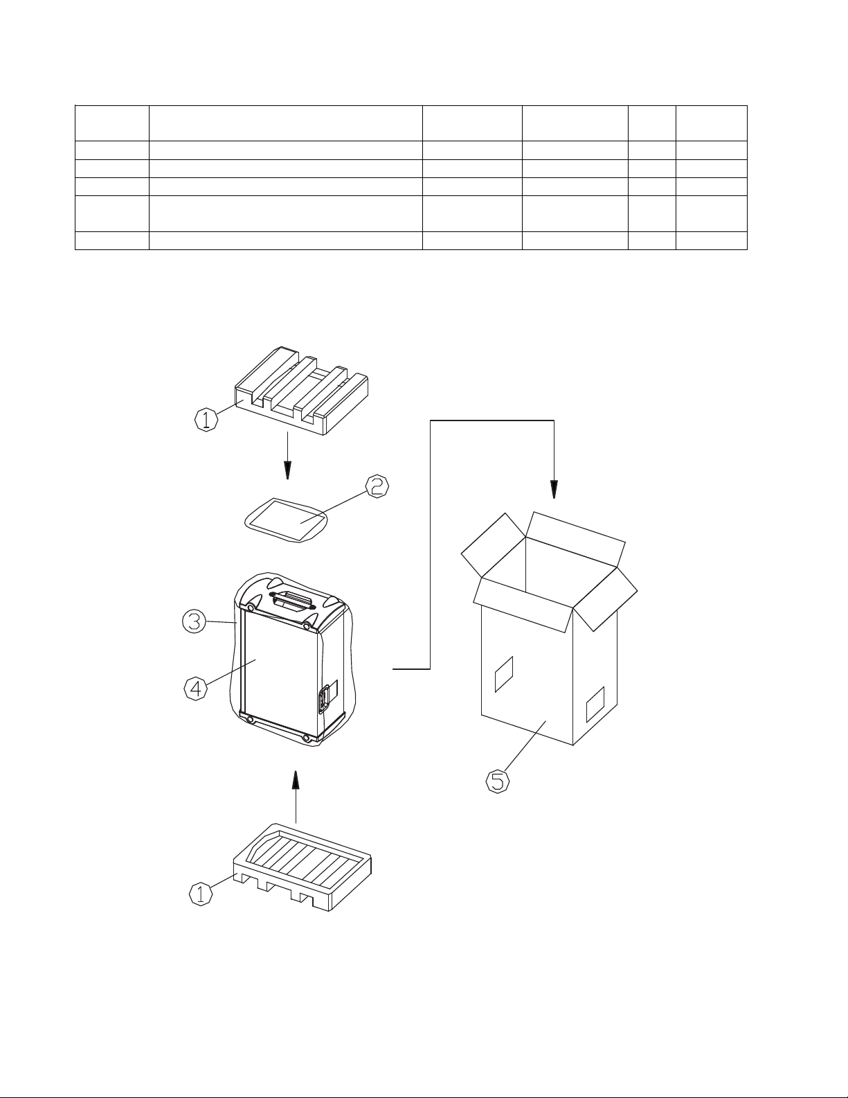
Packaging Part List
Item
Description Bose® Part
Vendor Part
Qty. Note
Panaray® MB4 Bass Loudspeaker (see Figure 1)
Number
1 PACKING FOAM 259317 145A-7570-0 2
2 OWNER’S MANUAL 259162 4301-5189-1 1
3 POLYBAG, 12” x 16” x 49” N/A 1497-4552- 0 1
4 MB4 BASS MODULE, BLACK
MB4 BASS MODULE, WHITE
5 CARTON 259316 145A-7590-0 1
Number
027054
027055
Number
FM000C
FM001C
1
Figure 1. Panaray MB4 Bass Loudspeaker Packaging View
4
Page 5

Main Part List
6
1
Part Number Item
Description
Qty Note
Panaray® MB4 Bass Loudspeaker System (see Figure 2)
Number
1 LOCKWASHER, LOGO - - 1
2 SPRING, LOGO - - 1
3 CUP WASHER, LOGO - - 1
4 GRILLE GASKET - - 1
5 GRILLE ASSY (WITH ITEMS 1, 2, 3 & 4) 298571 298572 1
6 SCREW, GRILLE, M4x28 298573 298573 4
7 PROTECTION CKT ASSY 298574 298575 1
8 TERMINAL PANEL 259193-1 259193-1 1
9 CONNECTOR, NEUTRIK 298548 298548 2
10 SCREW, NEUTRIK CONN, M3x12 - - 4
11 SCREW, TERMINAL PANEL, M4x16 - - 4
12 GASKET, WOOFER 298576 298576 4
13 WOOFER ASSEMBLY 298577 298577 4
14 SCREW, WOOFER, M4x16 - - 16
15 LOGO ASSY (WITH ITEMS 1, 2 & 3) 298578-001 298578-002 1
16 SCRIM FOR WHITE VERSION SPKR - - 1
Black White
Figure 2. Panaray
®
MB4 Bass Loudspeaker Exploded View
5
Page 6

Disassembly Procedures
61
Note: Refer to the figure below for the
following procedures.
1. Terminal Panel Removal
1.1 Using a Phillips-head screwdriver,
remove the four screws (11) that secure the
terminal panel (8) to the loudspeaker cabinet.
1.2 Gently pull the terminal panel away from
the cabinet. Be careful not to mark the
surface of the terminal panel or the cabinet.
1.3 Unplug the wiring harness from the PCB.
2. Grille Assembly Removal
2.1 Using an M4 torx-head screwdriver,
remove the four screws (6) that secure the
grille assembly (5) to the plastic end caps.
2.2 Gently pull the grille assembly (5) off of
the cabinet.
3. Woofer Assembly Removal
3.1 Perform procedure 2.
3.2 Using a Phillips-head screwdriver,
remove the four screws (14) that secure
the woofer assembly (13) that you wish to
remove to the loudspeaker cabinet.
3.3 Lift the woofer assembly out of the
cabinet and unplug the wires from the
woofer terminals.
Note: Be sure to replace the woofer gasket
(12) when you replace the woofer assembly.
4. Logo Removal
4.1 Perform procedure 2.
4.2 Clip off the lock washer (1) from the logo
assembly. Hold the spring (2) while clipping
the lock washer as the spring may fly off.
4.3 Pull the logo (15), cup washer (3),
spring and lock washer away from the grille.
6
Page 7

P
ower AmAm
plifieier
INPUT
OUTPUT
Audio
Audio
Signal
Generator
Generato
Test Procedures
Signa
owe
INPU
Figure 3. Panaray® MB4 Test Setup Diagram
1. Air Leak Test
1.1 Set up the system for test as shown in
Figure 3.
1.2 Apply a 100 Hz, 10 Vrms sine wave to
the input connectors.
1.3 Listen carefully for any air leaks from
around the end cap, drivers and the baffle.
Air leaks will be heard as a hissing or sputtering sound. All repairs must be hidden.
Test duration should be 5 seconds minimum.
2. Rub and Tick Test
pli
OUTPU
3. Phase Test
If the noise stays the same, it is normal
suspension noise and the driver is fine.
Suspension noise will not be heard with
program material.
3.1 Apply 10 VDC to the loudspeaker input
connector. Apply the positive to pin “1+” and
the negative to pin “1-” of the Neutrik
®
connector.
3.2 When applying the DC voltage level,
observe the driver cones. They should all
move outward when the DC level is applied.
2.1 Perform disassembly procedure 3. It is
not necessary to unplug the wires at the
driver assembly terminals.
2.2 Connect a signal generator directly to
the terminals of the driver under test.
2.3 Apply a 10 Hz, 10 Vrms sine wave to the
driver assembly.
2.4 Listen carefully for any extraneous
noises, such as rubbing, scraping or ticking.
Note: To distinguish between normal suspension noise and rubs or ticks, displace the
cone slightly with your fingers.
3.3 Rewire any incorrectly wired driver.
4. System Sweep Test
4.1 Set up the system for test as shown in
Figure 3.
4.2 Apply a 10 Hz, 10 Vrms sine wave to the
loudspeaker input connector.
4.3 While listening to the output of the
system, sweep the input frequency slowly
from 10 Hz to 400 Hz.
4.4 Listen carefully for any extraneous
noises such as buzzing or ticking.
7
Page 8

Part List
Item
Description Part Number Qty. Note
Panaray® MB4 Bass Loudspeaker Protection Circuit Board (see Figure 4)
Number
1 LAMP, GREEN DOT 298554 2
2 POLYSWITCH, RXE075 298555-075 1
Figure 4. MB4 Bass Loudspeaker Protection Board Layout
8
Page 9

PTC
LAMP
protective
lamp
polyswitch
PCB
Y
ELLOW
WOOFER 4
WOOFER 3
BLACK
BLUE
WOOFER 2
WOOFER 1
RED
BLACK
BLUE
PC
protective
LAM
PT
lam
WOOFER
RE
polyswitc
BL
ELL
BL
BL
WOOFER
WOOFER
WOOFER
Figure 5. Panaray
®
MB4 Bass Loudspeaker Wiring Diagram
9
Page 10

Service Manual Revision History
Date Revision
Description of Change Change Driven
Pages
Level
1/02 00 Document released at revision 00. Service manual
10/06 01 Added RoHS compliant part numbers. RoHS initiative 4, 5
By
release
Affected
All
10
Page 11

SPECIFICATIONS AND FEATURES SUBJECT TO CHANGE WITHOUT NOTICE
Bose Corporation
The Mountain
Framingham Massachusetts USA 01701
P/N: 259321-SM Rev. 01 10/2006 (P)
http://serviceops.bose.com
 Loading...