

Page 1
Panaray® MA12 Modular Line Array
Loudspeaker System
©2006 Bose Corporation
Service Manual
Reference Number 263639-SM Rev. 01
Electronic Copy Only
Page 2

Contents
Warranty.............................................................................................................................................2
Specifications....................................................................................................................................3
Product Description..........................................................................................................................3
Accessories Used with the MA12 Loudspeaker System...............................................................3
Part List Notes...................................................................................................................................3
Packaging Part List, Panaray® MA12 Loudspeaker System (see Figure 1) .................................4
Figure 1. Panaray MA12 Loudspeaker Packaging View ..................................................................4
Main Part List, Panaray MA12 Loudspeaker System (see Figure 2) ............................................5
Figure 2. Panaray MA12 Loudspeaker System Exploded View .......................................................6
Part List, Panaray MA12 Loudspeaker Protection Circuit Board (see Figure 3).........................7
Figure 3. MA12 Protection Circuit Board Layout Diagram................................................................7
Figure 4. Panaray MA12 Loudspeaker Wiring Diagram...................................................................8
Disassembly Procedures .................................................................................................................9
Test Procedures ..............................................................................................................................10
Figure 5. Panaray MA12 Test Setup Diagram ................................................................................10
Service Manual Revision History...................................................................................................11
®
CAUTION: The Bose
contains no user-serviceable parts. To prevent warranty infractions,
refer servicing to warranty service stations or factory service.
THIS DOCUMENT CONTAINS PROPRIETARY INFORMATION OF
BOSE CORPORATION WHICH IS BEING FURNISHED ONLY FOR
THE PURPOSE OF SERVICING THE IDENTIFIED BOSE PRODUCT
BY AN AUTHORIZED BOSE SERVICE CENTER OR OWNER OF
THE BOSE PRODUCT, AND SHALL NOT BE REPRODUCED OR
USED FOR ANY OTHER PURPOSE.
Panaray MA12 Modular Line Array Loudspeaker System
PROPRIETARY INFORMATION
Warranty
The Bose Panaray MA12 Modular Line Array Loudspeaker System is covered by a limited
5-year transferable limited warranty.
2
Page 3
Specifications
Description
Product Code
External Dimensions: 38.5 x 4.2 x 5.1 in. (978 x 107 x 130 mm)
Weight: Single Speaker: 22 lb. (10 kg)
Packed System: 24 lb. (11 kg)
Sensitivity: 88dB SPL, 120 Hz - 15 kHz (1W/1m free space)
System Protection: PTC, lamp
Impedance: 8 Ohms nominal, 7.5 Ohms minimum
Power Handling: 300 Watts continuous per IEC-268-5, 120 Hz high pass,
96 hours. Recommended amplifier power 150-300 Watts
Product Description
The Bose® Panaray® MA12 Modular Line Array Loudspeaker System is a modular system used
for mid/high frequency sound reproduction. It is a vented enclosure design using 12 full range
drivers housed in a closely spaced line.
The loudspeaker provides a means for mechanical attachment of two units to form a rigid single
line source by using the CB-MA12 coupling bracket (see table below). Each loudspeaker has
two Neutrik® connectors and one barrier style terminal so that multiple units can be connected
as a system in series and parallel.
The Bose Panaray MA12 Loudspeaker can be used with the Bose Panaray MB4 Modular Bass
Loudspeaker for dynamic full range reproduction.
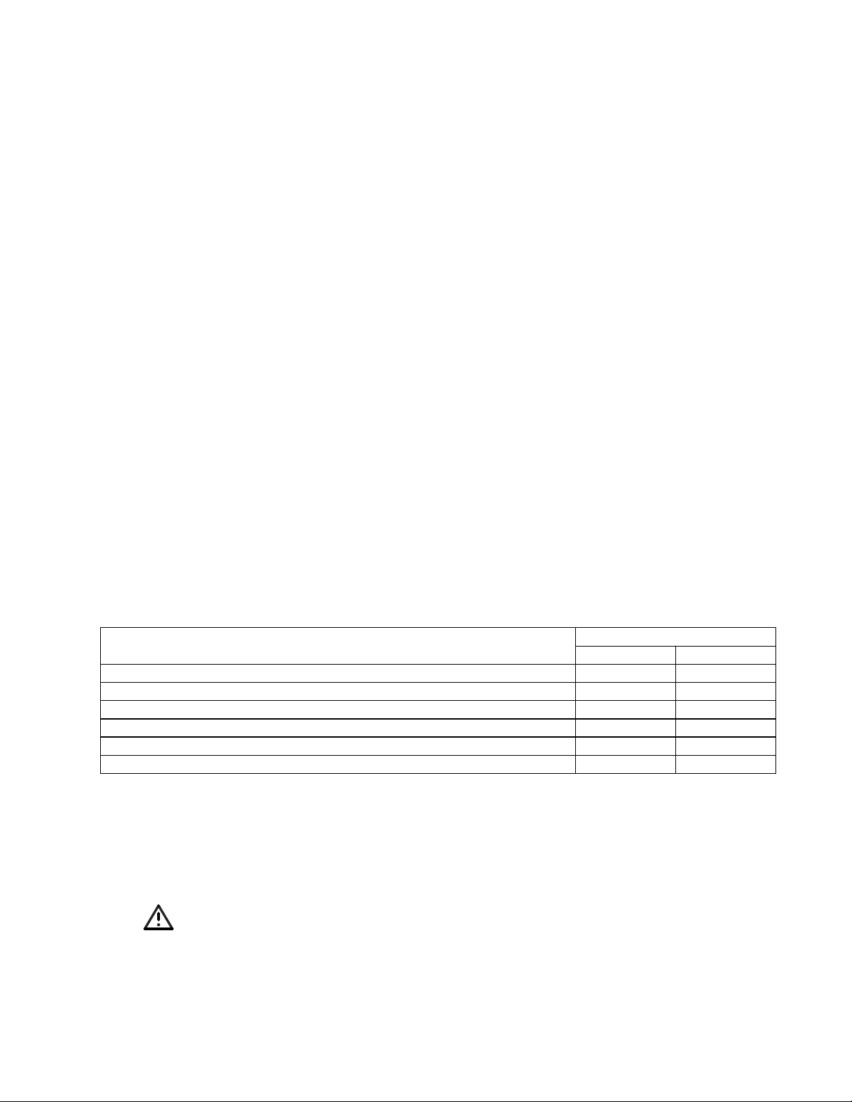
Accessories Used with the MA12 Loudspeaker System
WB-MA12 wall mount bracket (0º – 10º pitch) 028333 028334
WBP-MA12 wall mount bracket (0º – 10º pitch, +/- 90º yaw) 028673 028674
CB-MA12 coupling bracket 028337 028338
PSA-12 stand adapter 029229 CVT-12 70V/100V transformer (non-RoHS complaint) 029388 029389
CVT-12 70V/100V transformer (RoHS complaint) 040190 040191
Black White
Part List Notes
1. This part is not normally available from Customer Service. Approval from the Field Service
Manager is required before ordering.
2. The individual parts located on the PCBs are listed in the Electrical Part List.
3. This part is critical for safety purposes. Failure to use a substitute replacement with the
same safety characteristics as the recommended replacement part might create shock, fire
and/or other hazards.
4. This part is referenced for informational purposes only. It is not stocked as a repair part. Refer
to the next higher assembly for a replacement part.
3
Page 4
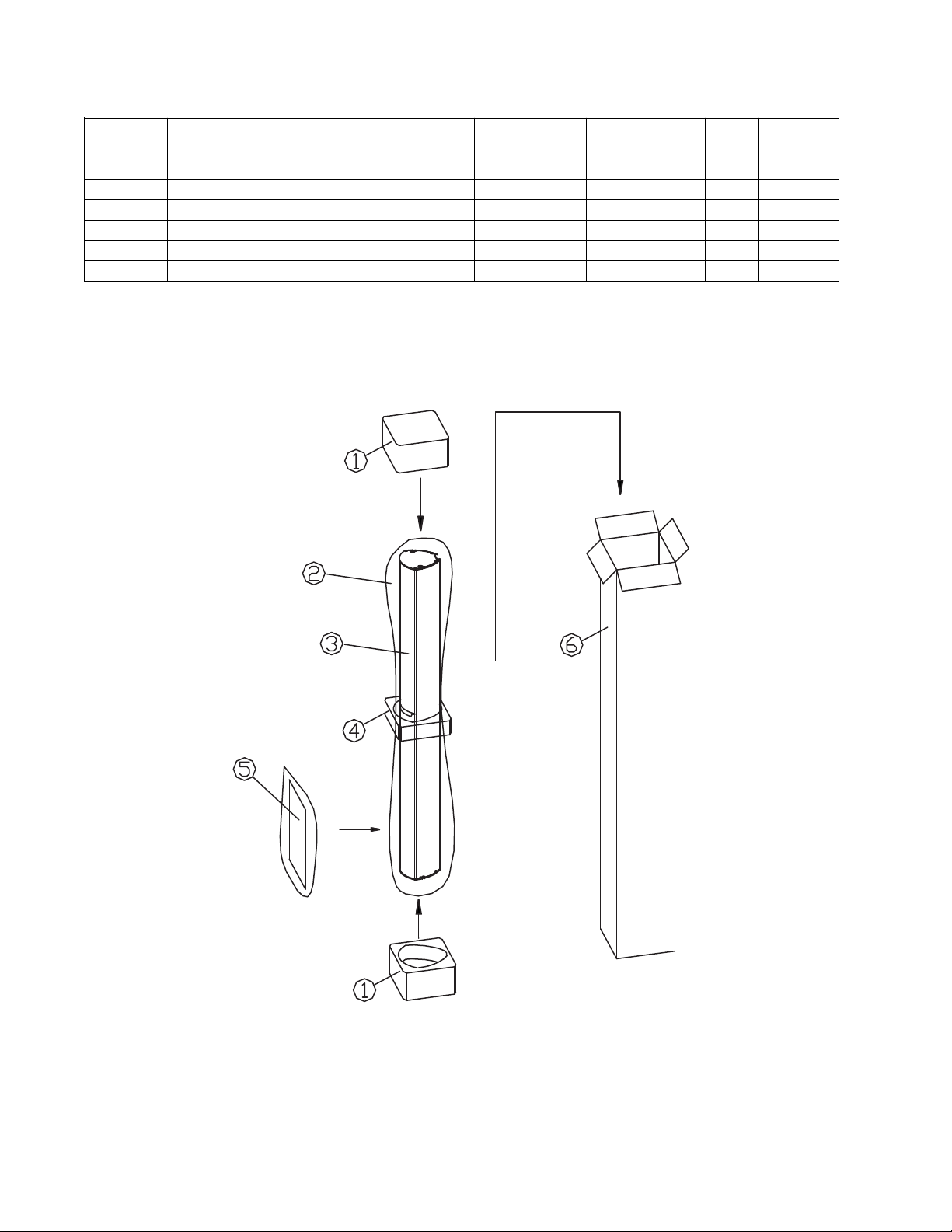
Packaging Part List
Item
Description Bose® Part
Vendor Part
Qty. Note
ESOB
Panaray® MA12 Loudspeaker System (see Figure 1)
Number
1 PACKING, END CAP 263624 1490-7393-0 2
2 POLYBAG N/A 1497-5102-0 1
3 MA12 LOUDSPEAKER REF REF 1
4 PACKING, CENTER 263625 1490-7433-1 1
5 OWNER’S MANUAL 263626 4301-5191-0 1
6 CARTON 263572 145A7780-0 1
Number
Number
Figure 1. Panaray MA12 Loudspeaker Packaging View
4
Page 5

Main Part List
Part Number Item
Description
Qty Note
3
1
2
6
5
4
7
8
9
01
11
2
1
31
4
1
61
5
1
Panaray® MA12 Loudspeaker System (see Figure 2)
Number
1 SCREW, CONNECTOR, M3x13 - - 4 4
2 CONNECTOR, NEUTRIK 298548 298548 2
3 GASKET, ENDCAP 259133 259133 2
4 SCREW, ENDCAP, M3.5x13 - - 12 4
5 ENDCAP 259132-001 259132-002 2
6 GASKET, DRIVER 298549 298549 12
7 DRIVER, 2.25” 298550 298550 12
8 SCREW, BAFFLE, M4.5x12 - - 16 4
9 SCREW, DRIVER, M3.5x8 - - 48 4
10 U-CHANNEL, GRILLE - - 2M 4
12 LOGO, BOSE 298552-001 298552-002 1
11 GRILLE 298551-001 298551-002 1
13 U-CHANNEL FOR GRILLE COVER - - .35M
14 GRILLE TRIM - - 2 4
15 BARRIER TERMINAL - - 1 4
16 SCREW, BARRIER TERMINAL,
M3x14
- CVT-12 TRANSFORMER
(ACCESSORY ITEM)
Black White
- - 2 4
040190 040191 1
4
3
Figure 2. Panaray® MA12 Loudspeaker System Exploded View
5
Page 6

Part List
Item
Description Part Number Qty. Note
Panaray® MA12 Loudspeaker Protection Circuit Board (see Figure 3)
Number
PCB ASSY, PROTECTION CKT 298553 1
1 LAMP, GREEN DOT 298554 2
2 POLYSWITCH, RXE075 298555-075 1
Figure 3. MA12 Protection Circuit Board Layout Diagram
6
Page 7

PTC
LAMP
Screw
Terminal
LAM
P
Screw
Terminal
Figure 4. Panaray
®
MA12 Loudspeaker Wiring Diagram
7
Page 8

Disassembly Procedures
3
1
2
6
5
4
7
8
9
01
11
2
1
31
4
1
61
5
1
Note: Refer to the figure below for the
following procedures.
1. End Cap Removal
1.1 Using a Phillips-head screwdriver,
remove the six screws (4) that secure the
steel end cap (5) to the housing and grille
trim.
1.2 Gently pull the end cap away from the
housing.
Re-assembly Note: When replacing the end
cap, ensure that it is fully seated against the
housing for an airtight seal. Replace all six
screws to prevent air leaks.
2. Grille Assembly Removal
2.1 Remove the two screws at the front of
each end cap.
2.3 Gently pull the grille assembly away
from the housing. Be careful not to mark
the surface of the grille or the housing.
3. Driver Removal
3.1 Perform procedure 2.
3.2 Using a Phillips-head screwdriver,
remove the sixteen screws (8) that secure
the baffle to the housing.
3.3 Lift the baffle with the six drivers (7) out
of the housing.
3.4 Unplug the driver cable wires from the
driver you wish to remove.
3.5 Using a Phillips-head screwdriver,
remove the four screws (9) that secure the
driver to the baffle. Lift out the driver.
2.2 Take the grille trim (14) along with the Urubber channel (13) away from the end of
the grille (11).
3
8
Page 9

Test Procedures
Audio Signal
Generator
Power Amplifier
INPUT OUTPUT
Figure 5. Panaray® MA12 Test Setup Diagram
1. Air Leak Test
1.1 Set up the system for test as shown in
Figure 5.
1.2 Apply a 100 Hz, 10 Vrms sine wave to
the input connectors.
1.3 Listen carefully for any air leaks from
around the end cap, drivers and the baffle.
Air leaks will be heard as a hissing or sputtering sound. All repairs must be hidden.
Test duration should be 5 seconds minimum.
2. Rub and Tick Test
2.1 Perform disassembly procedure 3. It is
not necessary to unplug the wires at the
driver assembly terminals.
2.2 Connect a signal generator directly to
the terminals of the driver under test.
If the noise stays the same, it is normal
suspension noise and the driver is fine.
Suspension noise will not be heard with
program material.
3. Phase Test
3.1 Momentarily apply 10 VDC to the loud-
speaker input connector. Apply the positive
to pin “1+” and the negative to pin “1-” of the
®
Neutrik
connector.
3.2 When applying the DC voltage level,
observe the driver cones. They should all
move outward when the DC level is applied.
3.3 Rewire any incorrectly wired driver.
4. System Sweep Test
4.1 Set up the system for test as shown in
Figure 5.
2.3 Apply a 20 Hz, 5 Vrms sine wave to the
driver assembly.
2.4 Listen carefully for any extraneous
noises, such as rubbing, scraping or ticking.
Note: To distinguish between normal suspension noise and rubs or ticks, displace the
cone slightly with your fingers.
4.2 Apply a 10 Hz, 10 Vrms sine wave to the
loudspeaker input connector.
4.3 While listening to the output of the
system, sweep the input frequency slowly
from 10 Hz to 20 kHz.
4.4 Listen carefully for any extraneous
noises such as buzzing or ticking.
9
Page 10

Service Manual Revision History
Date Revision
Description of Change Change Driven
Pages
Level
1/02 00 Document released at revision 00. Service manual
10/06 01 Added RoHS compliant part numbers. RoHS initiative 4, 6
By
release
Affected
All
10
Page 11

SPECIFICATIONS AND FEATURES SUBJECT TO CHANGE WITHOUT NOTICE
Bose Corporation
The Mountain
Framingham Massachusetts USA 01701
P/N: 263639-SM Rev. 01 10/2006 (P)
http://serviceops.bose.com
 Loading...