

Bose LIFESTYLE 535, LIFESTYLE 525 series II, Lifestyle 520, Lifestyle 510, Lifestyle 535 Series II Setup Manual
Page 1
LIFESTYLE® 535/525 series II
home entertainment systems
LIFESTYLE® 520/510
home theater systems
Setup Guide | Guía de instalación | Guide d’installation
Page 2
Safety Information
Please read this guide
Please take the time to follow the instructions in this owner’s guide carefully. It will help you set up and operate your
system properly and enjoy its advanced features. Please save this guide for future reference.
All Bose
®
products must be used in accordance with local, state, federal, and industry regulations.
7KHOLJKWQLQJÀDVKZLWKDUURZKHDGV\PEROZLWKLQDQHTXLODWHUDOWULDQJOHDOHUWVWKHXVHUWRWKHSUHVHQFHRI
XQLQVXODWHGGDQJHURXVYROWDJHZLWKLQWKHV\VWHPHQFORVXUHWKDWPD\EHRIVXI¿FLHQWPDJQLWXGHWR
constitute a risk of electric shock.
7KHH[FODPDWLRQSRLQWZLWKLQDQHTXLODWHUDOWULDQJOHDVPDUNHGRQWKHV\VWHPLVLQWHQGHGWRDOHUWWKHXVHU
to the presence of important operating and maintenance instructions in this owner’s guide.
WARNING: Contains small parts which may be a choking hazard. Not suitable for children under age 3.
WARNINGS:
7RUHGXFHWKHULVNRI¿UHRUHOHFWULFDOVKRFNGRQRWH[SRVHWKHSURGXFWWRUDLQRUPRLVWXUH
'RQRWH[SRVHWKLVDSSDUDWXVWRGULSSLQJRUVSODVKLQJDQGGRQRWSODFHREMHFWV¿OOHGZLWKOLTXLGVVXFK
DVYDVHVRQRUQHDUWKHDSSDUDWXV$VZLWKDQ\HOHFWURQLFSURGXFWVXVHFDUHQRWWRVSLOOOLTXLGVLQWR
DQ\SDUWRIWKHV\VWHP/LTXLGVFDQFDXVHDIDLOXUHDQGRUD¿UHKD]DUG
To prevent electric shock, match the wide blade of the line cord plug to the wide slot of the AC (mains)
receptacle. Insert fully.
'RQRWSODFHDQ\QDNHGÀDPHVRXUFHVVXFKDVOLJKWHGFDQGOHVRQRUQHDUWKHDSSDUDWXV
CAUTIONS:
0DNHQRPRGL¿FDWLRQVWRWKHV\VWHPRUDFFHVVRULHV8QDXWKRUL]HGDOWHUDWLRQVPD\FRPSURPLVHVDIHW\
regulatory compliance, and system performance.
Long-term exposure to loud music may cause hearing damage. It is best to avoid extreme volume
when using headphones, especially for extended periods.
7KHWHUPV+'0,DQGWKH+'0,/RJRDUHWUDGHPDUNVRUUHJLVWHUHGWUDGHPDUNVRI+'0,/LFHQVLQJ//&LQWKH8QLWHG
States and other countries.
%RVH&RUSRUDWLRQ1RSDUWRIWKLVZRUNPD\EHUHSURGXFHGPRGL¿HGGLVWULEXWHGRURWKHUZLVHXVHGZLWKRXW
written permission.
2 - English
Page 3
Safety Information
NOTES:
The product label is located on the bottom or the back of the product.
Where the mains plug or appliance coupler is used as the disconnect device, such disconnect device shall
remain readily operable.
The product must be used indoors. It is neither designed nor tested for use outdoors, in recreation vehicles, or
on boats.
This product is intended to be used only with the power supply provided.
The speaker wire and interconnect cables included with the system are not approved for in-wall installation.
3OHDVHFKHFN\RXUORFDOEXLOGLQJFRGHVIRUWKHFRUUHFWW\SHRIZLUHDQGFDEOHUHTXLUHGIRULQZDOOLQVWDOODWLRQ
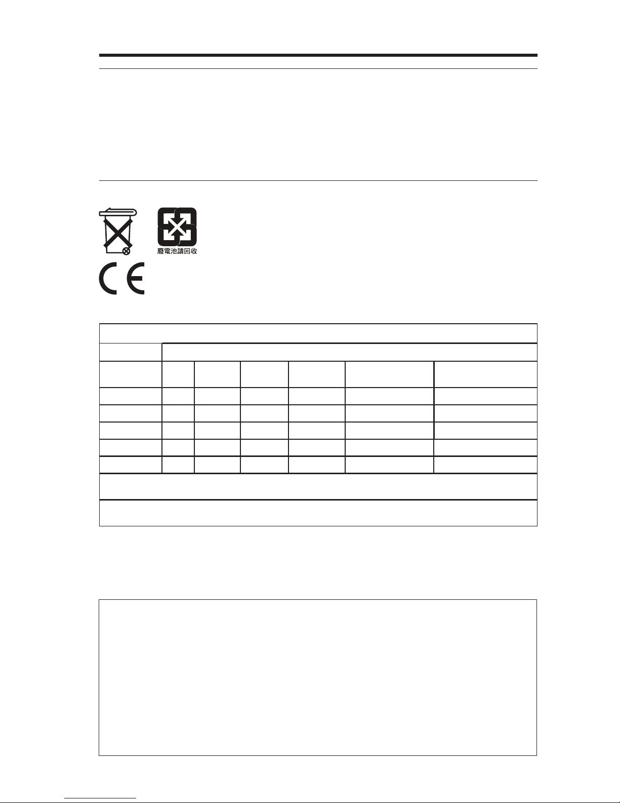
Please dispose of used batteries properly
, following any local regulations.
Do not incinerate.
Bose®&RUSRUDWLRQKHUHE\GHFODUHVWKDWWKLVSURGXFWLVLQFRPSOLDQFHZLWKWKHHVVHQWLDOUHTXLUHPHQWV
DQGRWKHUUHOHYDQWSURYLVLRQVRI'LUHFWLYH(&DQGDOORWKHUDSSOLFDEOH(8GLUHFWLYHUHTXLUHPHQWV7KHFRPSOHWHGHFODUDWLRQRIFRQIRUPLW\FDQEHIRXQGDWZZZ%RVHFRPFRPSOLDQFH
Names and Contents of Toxic or Hazardous Substances or Elements
Part Name
Lead
(Pb)
PCBs X 0 0 0 0 0
Metal parts X 0 0 0 0 0
Plastic parts 0 0 0 0 0 0
Speakers X 0 0 0 0 0
Cables X 0 0 0 0 0
0: Indicates that this toxic or hazardous substance contained in all of the homogeneous materials for this part is below the limit
UHTXLUHPHQWLQ6-7
X: Indicates that this toxic or hazardous substance contained in at least one of the homogeneous materials used for this part is
DERYHWKHOLPLWUHTXLUHPHQWLQ6-7
Mercury
(Hg)
Toxic or Hazardous Substances and Elements
Cadmium
(Cd)
Hexavalent
(CR(VI))
Polybrominated
Biphenyl (PBB)
Polybrominated
diphenylether (PBDE)
Please complete and retain for your records.
The serial and model numbers can be found on the bottom panel of the product.
Lifestyle
Control console serial number: _____________________________________________________
Acoustimass
Speaker array serial number:_______________________________________________________
Purchase date: ___________________________________________________________________
Please keep your receipt together with this Setup Guide and the Operating Guide.
®
model:__________________________________________________________________
®
serial number: _______________________________________________________
English - 3
Page 4

Safety Information
Important Safety Instructions
1. Read these instructions.
2. Keep these instructions.
3. Heed all warnings.
4. Follow all instructions.
Do not use this apparatus near water.
Clean only with a dry cloth.
7. Do not block any ventilation openings. Install in accordance with the manufacturer’s instructions.
8. Do not install near any heat sources such as radiators, heat registers, stoves, or other apparatus (including
DPSOL¿HUVWKDWSURGXFHKHDW
9. Do not defeat the safety purpose of the polarized or grounding-type plug. A polarized plug has two blades
with one wider than the other. A grounding type plug has two blades and a third grounding prong. The wide
EODGHRUWKHWKLUGSURQJDUHSURYLGHGIRU\RXUVDIHW\,IWKHSURYLGHGSOXJGRHVQRW¿WLQWR\RXURXWOHWFRQVXOW
an electrician for replacement of the obsolete outlet.
10. Protect the power cord from being walked on or pinched particularly at plugs, convenience receptacles, and
the point where they exit from the apparatus.
11. 2QO\XVHDWWDFKPHQWVDFFHVVRULHVVSHFL¿HGE\WKHPDQXIDFWXUHU
12.
13. 8QSOXJWKLVDSSDUDWXVGXULQJOLJKWQLQJVWRUPVRUZKHQXQXVHGIRUORQJSHULRGVRIWLPH
14. 5HIHUDOOVHUYLFLQJWRTXDOL¿HGSHUVRQQHO6HUYLFLQJLVUHTXLUHGZKHQWKHDSSDUDWXVKDVEHHQGDPDJHGLQD
ZD\VXFKDVSRZHUVXSSO\FRUGRUSOXJLVGDPDJHGOLTXLGKDVEHHQVSLOOHGRUREMHFWVKDYHIDOOHQLQWRWKH
apparatus, the apparatus has been exposed to rain or moisture, does not operate normally, or has been
dropped.
8VHRQO\ZLWKWKHFDUWVWDQGWULSRGEUDFNHWRUWDEOHVSHFL¿HGE\WKHPDQXIDFWXUHURUVROGZLWKWKH
DSSDUDWXV:KHQDFDUWLVXVHGXVHFDXWLRQZKHQPRYLQJWKHFDUWDSSDUDWXVFRPELQDWLRQWRDYRLG
injury from tip-over
Additional safety information
See the additional instructions on the Important Safety Instructions sheet (North America only) enclosed in the
shipping carton.
4 - English
Page 5

Contents
Welcome
ank You............................................................................................................ 6
Unpacking ........................................................................................................... 6
System Setup
Control console box........................................................................................... 7
Acoustimass
Speaker box ........................................................................................................ 12
Interactive box ................................................................................................... 17
Other Box 4 items.............................................................................................. 19
Applying rubber feet ......................................................................................... 20
If you have setup problems ............................................................................. 21
Contacting customer service .......................................................................... 21
®
module box ............................................................................... 10
English - 5
Page 6

Welcome
ank You
Thank you for choosing a Bose® LIFESTYLE® system for your home. This guide
provides step-by-step instructions for setting up your new system. There are two
phases to the setup process:
Physical setup phase: Placing the system components and connecting them
together.
Interactive setup phase: Completing your setup following the interactive steps on
your TV screen provided by the UNIFY
®
intelligent integration system.
Unpacking
The parts of your new system are packaged in four numbered boxes plus a small
box containing the appropriate power cords:
1
s
Control console box
2
s Acoustimass
3
s Speaker box
4
s Interactive box
s
Power cord box (used with boxes 1 and 2)
Starting with Box 1, unpack each box and set up its contents before unpacking the
next one.
Be sure to save all of the packing materials. These provide the safest means for
any necessary shipping or transporting.
®
module box
If any part appears damaged, do not attempt to use it. Notify Bose or your
authorized Bose dealer immediately. For Bose contact information, refer to
the address sheet included in Box 4.
6 - English
Page 7
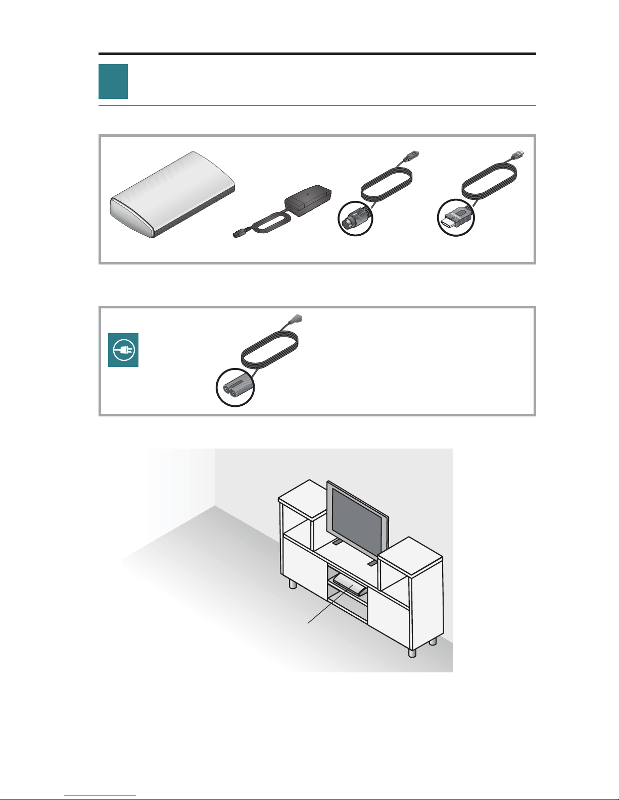
1
Control console box
What you need from box 1:
From box 1:
Control console
What you need from the power cord box:
From the power cord box:
Power supply Audio input cable HDMI
System Setup
®
cable
Power cord
A. Place the control console on a flat, stable surface near your TV.
Control console
Note: Until your system is completely installed, it may be helpful to keep the control
console positioned for easy access to its rear connection panel.
English - 7
Page 8
System Setup
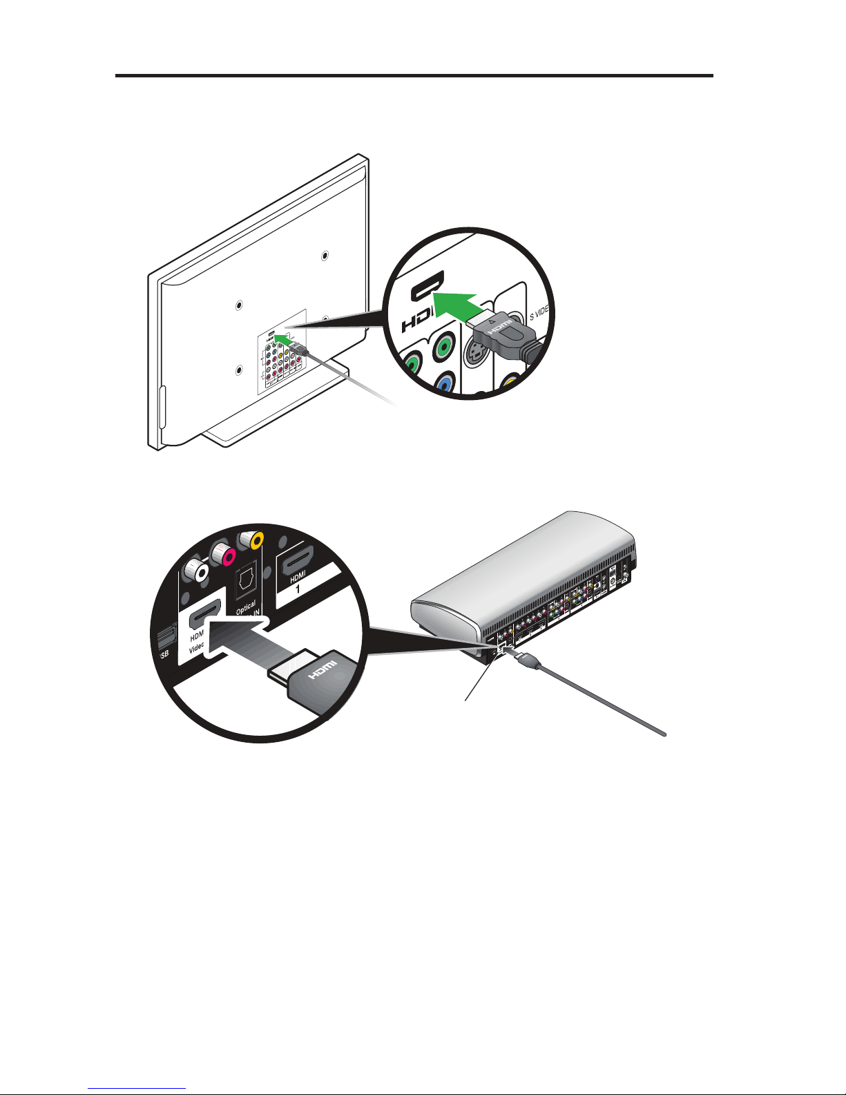
B. Plug one end of the HDMI® cable into an HDMI INPUT connector on your TV.
If an HDMI cable is already connected to an HDMI input on your TV, you can
use this one. Just disconnect the other end.
C. Plug the other end of the HDMI cable you are using into the connector labeled
HDMI OUT Video to TV on the control console.
HDMI OUT
Video to TV
8 - English
Page 9
System Setup
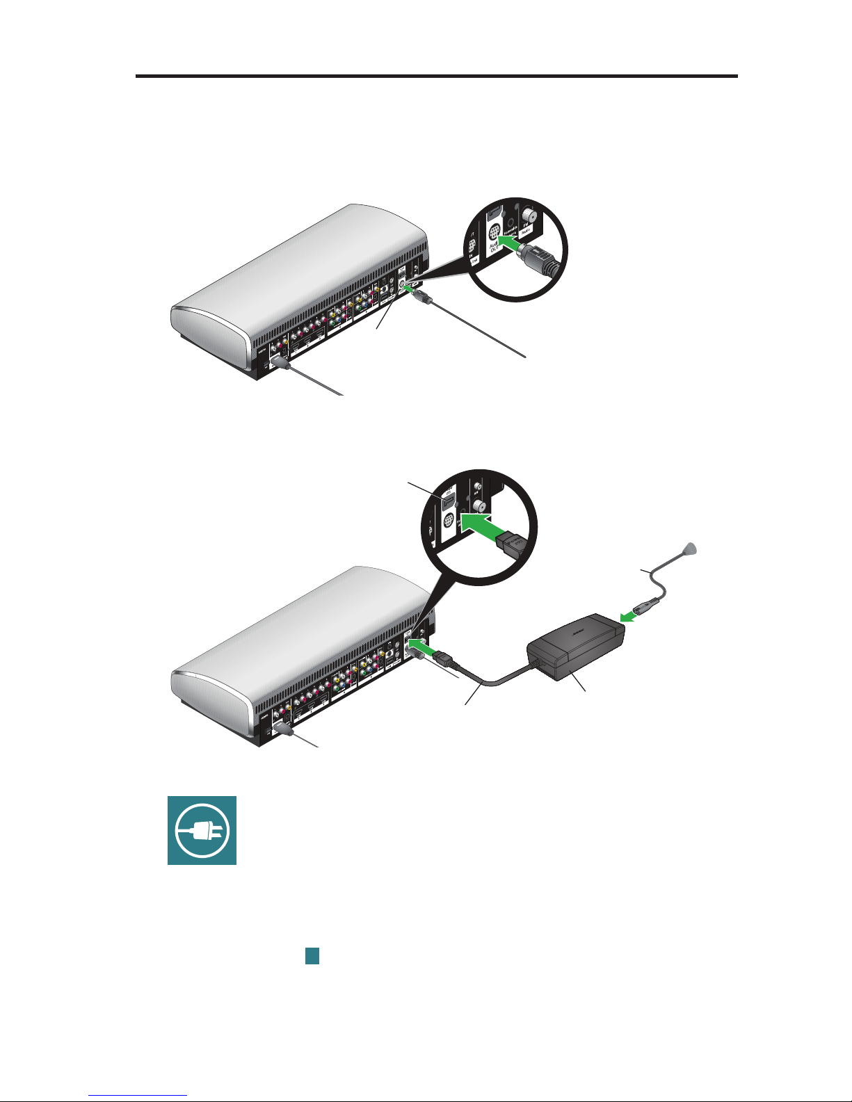
D. Plug one end of the audio input cable into the control console connector
labeled Audio OUT. Make sure the flat surface with the arrow on the plug
faces up.
Leave the other end of the cable on the floor. You will be asked to connect it
while setting up the contents of the next box.
Audio OUT
E. Plug the power supply output cord into the control console Power connector.
Power
Power supply
output cord
F. Remove a power cord from the power cord box.
AC power cord
Power supply
G. Plug one end of the power cord into the power supply.
the plug in as far as it can go.
H. Plug the other end of the power cord into a live AC (mains) power outlet.
I. Continue with Box
2
on the next page.
Make sure you push
English - 9
Page 10
System Setup
2
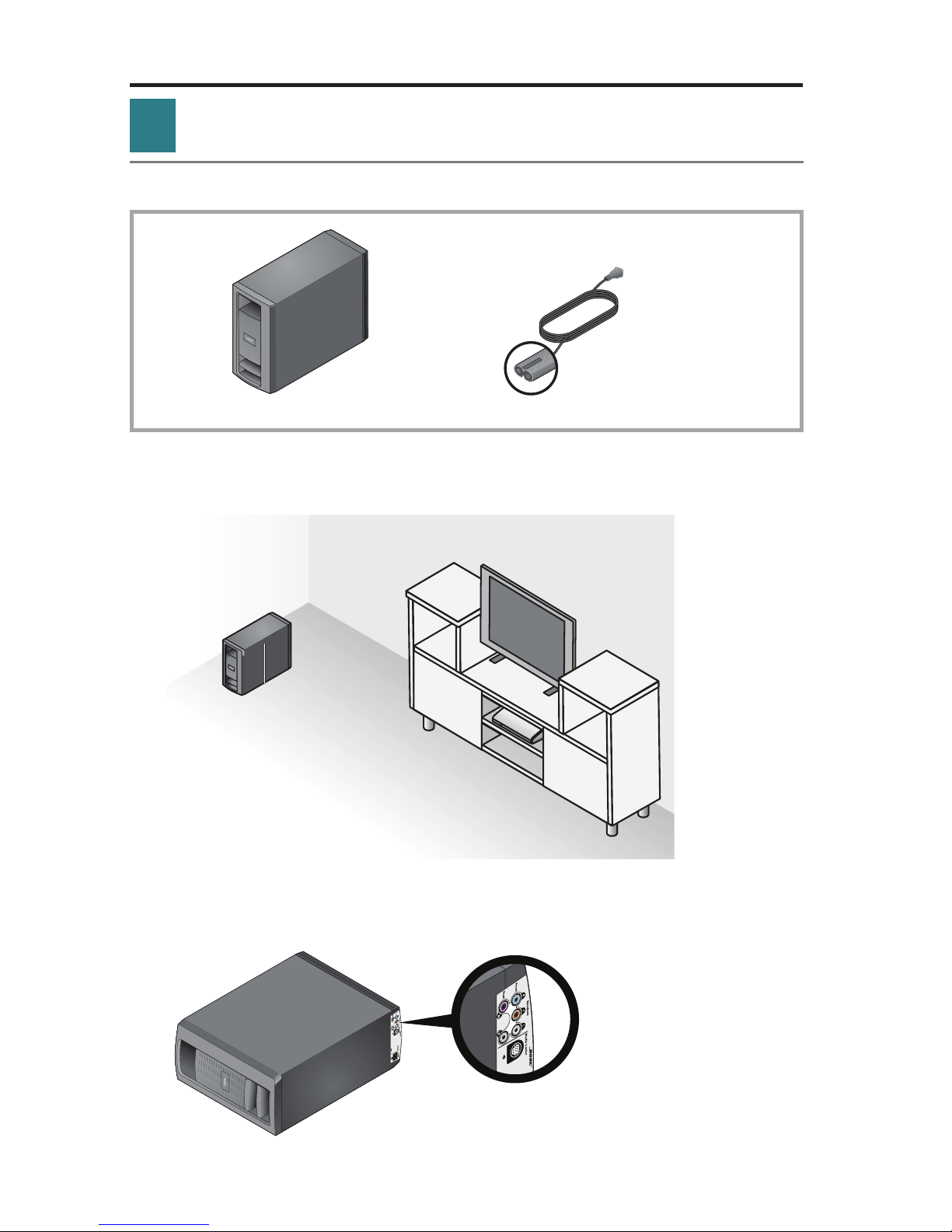
Acoustimass® module box
What you need for the following steps:
From box 2:
Acoustimass module
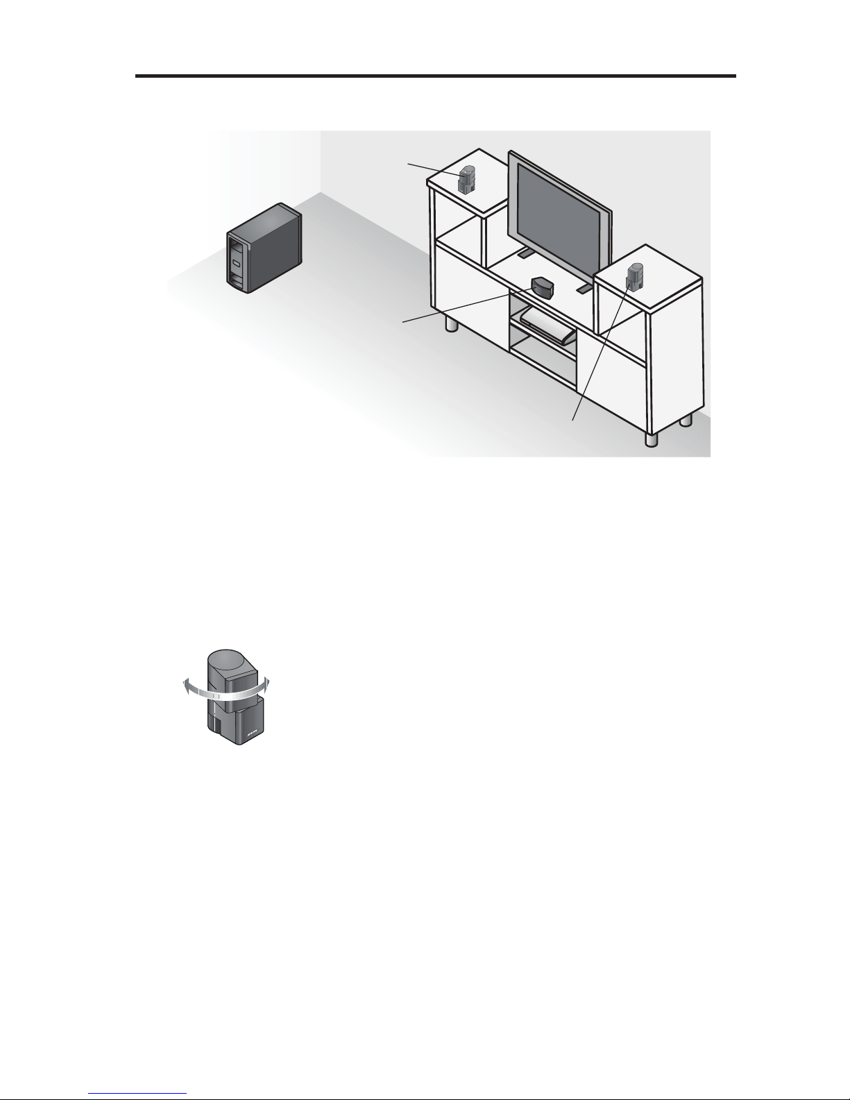
A. Place the Acoustimass module on the floor at the same end of the room
as the TV. Make sure there is a live AC (mains) power outlet nearby.
From the power
cord box:
Power cord
Acoustimass
module
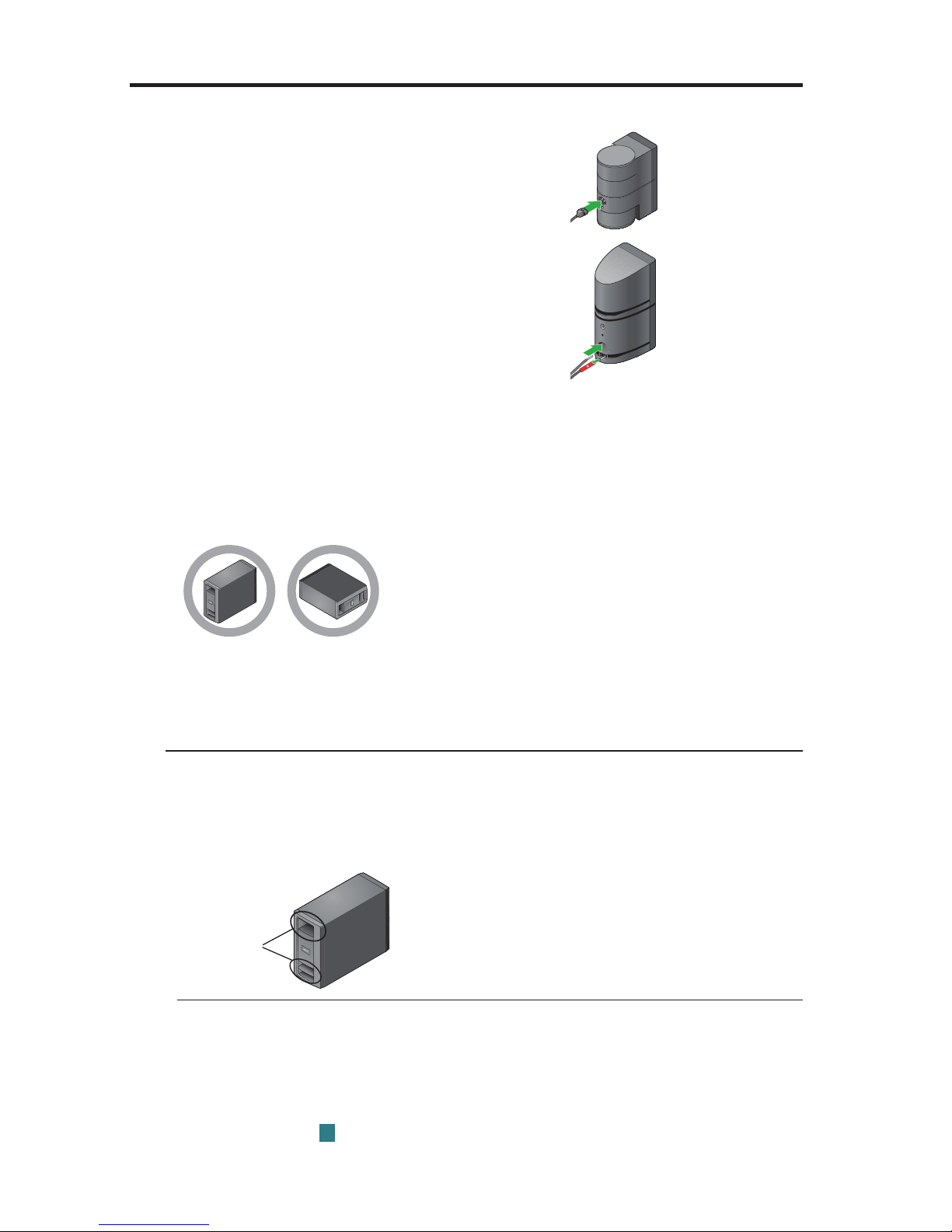
B. Lay the module on its side and locate the connector panel.
Connector
panel
10 - English
Page 11
System Setup
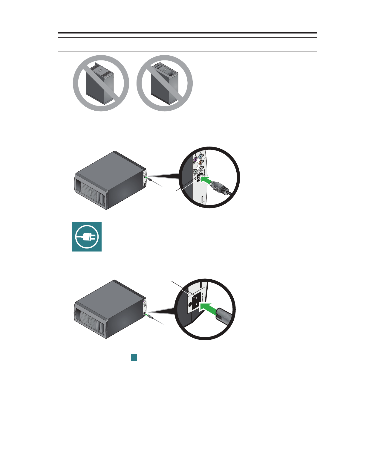
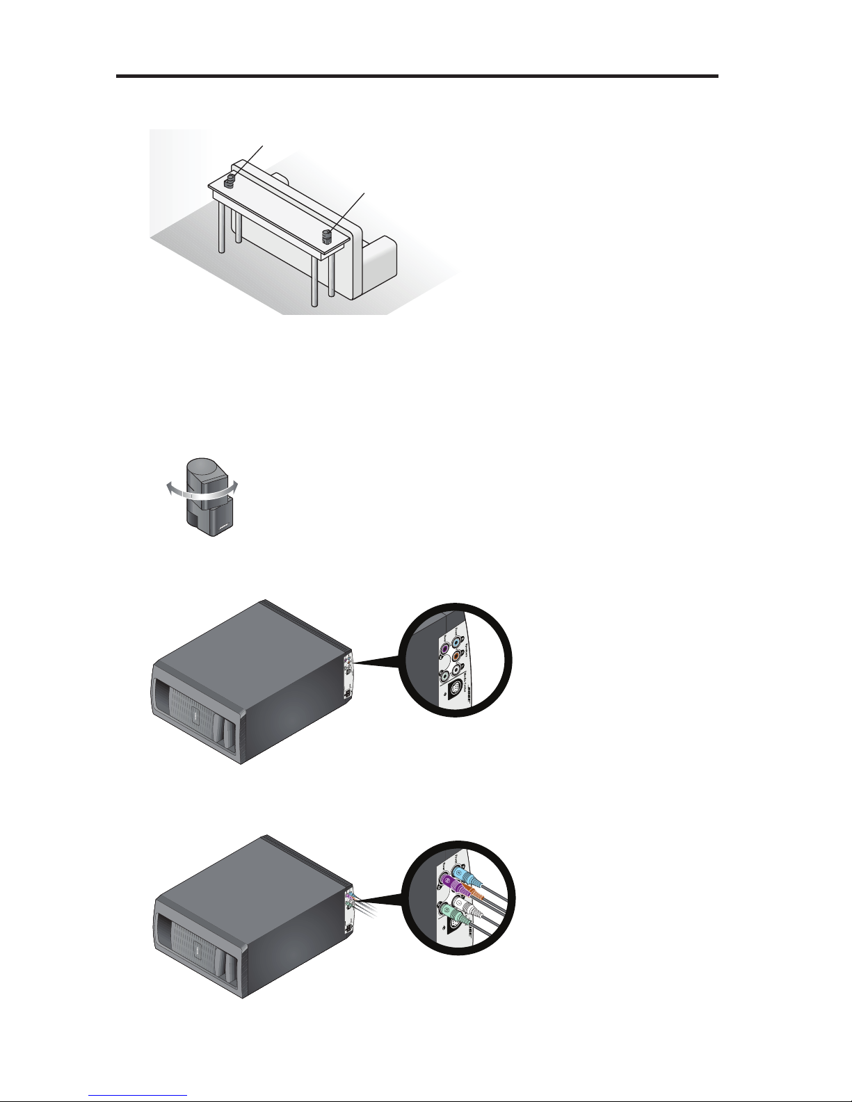
CAUTION: DO NOT stand the Acoustimass® module on its front or back end.
C. Plug the free end of the audio input cable into the Media Center connector
on the Acoustimass module.
Make sure the flat surface with the arrow faces the front of the module.
Media
center
D. Remove a power cord from the power cord box.
E. Plug one end of the power cord into the AC Power connector on the
Acoustimass module. Make sure you push the plug in as far as it can go.
AC power
F. Plug the other end of the power cord into a live AC (mains) power outlet.
G. Continue with Box
3
on the next page.
English - 11
Page 12
System Setup
3
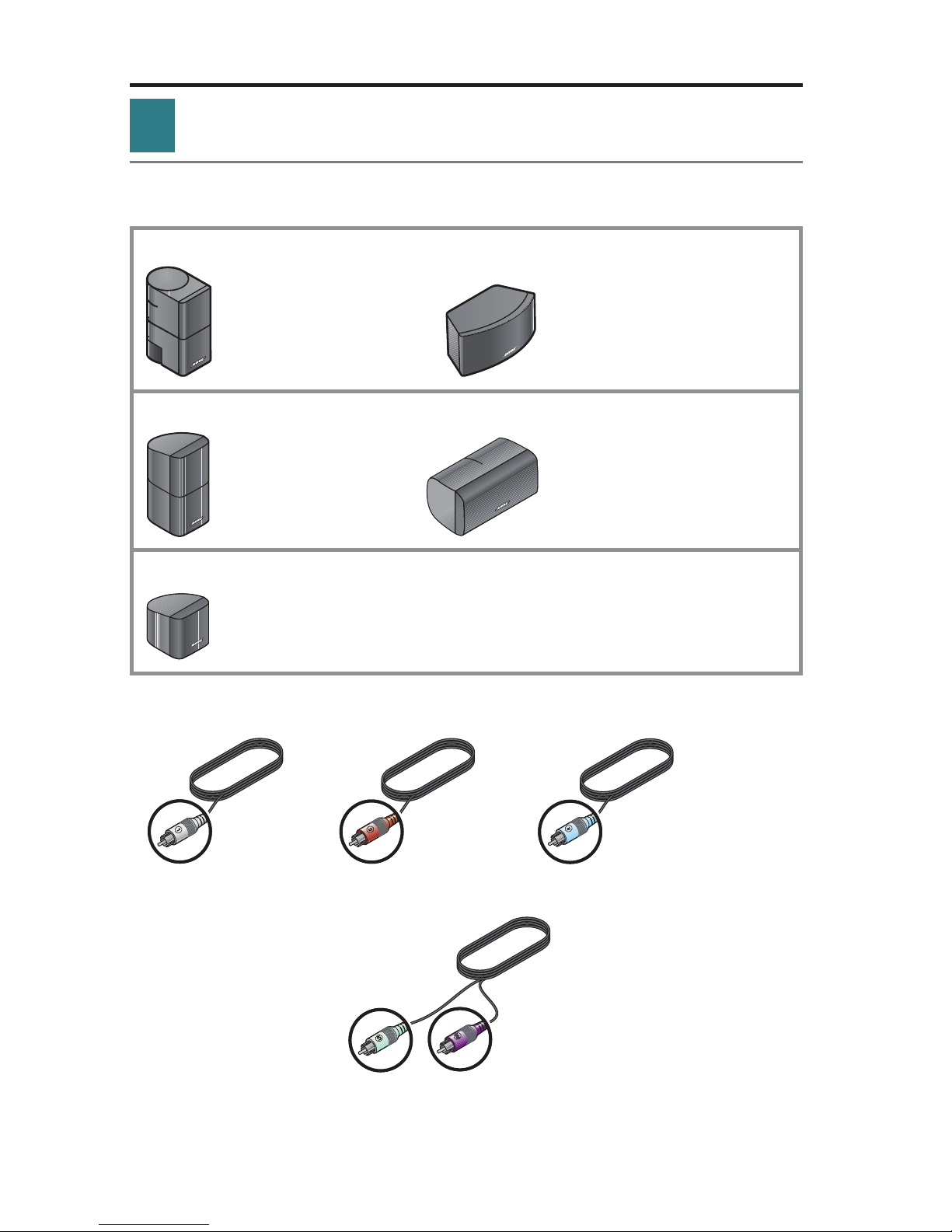
Speaker box
What you need for the following steps:
System speakers (one set of the three types shown)
Jewel Cube
®
speakers
(4) Left or right, front (1) Center front
or rear speaker speaker
Direct/Reflecting® cube speaker arrays
(4) Left or right, front (1) Center front
or rear speaker speaker
Virtually Invisible
(5) Left or right, front or rear, and center front speaker
®
single cube speakers
Front speaker cables
Left front (L) White Center front (C) Brown Right front (R) Light blue
Rear speaker cables
Left rear (LR)
Light green
Right rear (RR)
Purple
Note: You can place system speakers on wall brackets or floor stands. To purchase
®
these accessories, contact your local Bose
dealer or visit www.Bose.com.
12 - English
Page 13
System Setup
A. Place the center front speaker on a stable and level surface directly above or
below the center of your TV screen as in the following example.
Left front (L)
Center front (C)
Right front (R)
B. Place one speaker to the left and one to the right of the TV.
– Keep each speaker within 3 ft (1 m) of the TV screen to prevent too much
separation of the sound from the picture. Vary this distance to suit your
room conditions and personal preference.
– If placing the speakers in an enclosed bookcase shelf, position them at the
front edge of the shelf.
– Rotate the cubes so that one cube of each speaker points forward into the
room and the other points at a side wall to create reflected sound.
English - 13
Page 14
System Setup
C. Place the rear speakers toward the back of the room behind the viewers at ear
height (when seated) or higher, if possible.
Left rear (LR)
Right rear (RR)
– Make sure the 50 ft (15.2 m) rear speaker cables will reach from the speak-
ers to the Acoustimass
®
module.
– Aim the speakers away from the listeners to prevent them from pinpointing
the exact location of the sound source.
– Rotate the cubes so that one cube of each speaker points forward into the
room and the other points at a side wall to create reflected sound.
D. Locate the colored connectors on the bottom panel of the
Acoustimass
®
module.
Connector
panel
E. Plug the speaker cables into the Acoustimass module connectors. Be sure to
match each cable plug to each connector by the color code.
14 - English
Page 15
System Setup
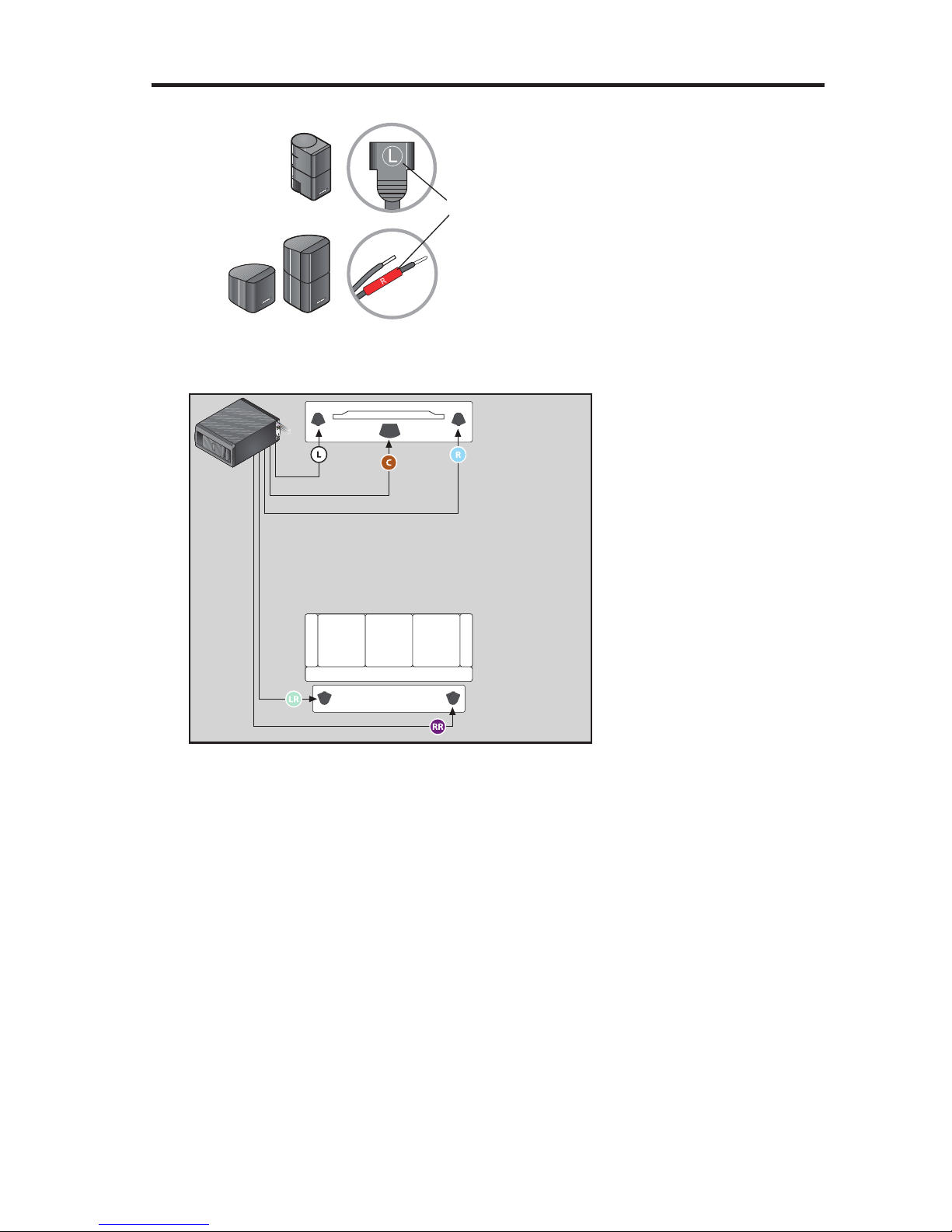
F. Locate the speaker position markings on the free ends of the speaker cables.
Speaker position marking
(L, C, R, LR, or RR)
G. Using the speaker position markings, run each cable out to its respective
speaker as in the following setup example of a room.
Front speakers
Rear speakers
English - 15
Page 16
System Setup
H. Connect the speaker cable to the type of speaker you have.
For Jewel Cube
Insert the plug into the speaker connector.
®
speakers:
For Direct/Reflecting® and
Virtually Invisible
®
single
cube speakers:
Press the button and insert the wires. Connect
the red-collared wire to the red connector.
Connect the other wire to the black connector.
Notes:
s The rear speaker cables for Direct/Reflecting
®
and Virtually Invisible® single
cube speakers are webbed together. You can pull them apart as needed.
s Put the Acoustimass
®
module in its final position:
– Upright (BEST) or on either side (ALTERNATE).
– With the front opening facing into the room.
– At least 18 in (45 cm) from any TV to avoid magnetic interference with the TV
image. Move it farther away if you still notice interference.
CAUTION:
s Do not put electronic media, such as video or audio tapes, on or next
to the Acoustimass
surrounding the module may erase some or all of the recorded material.
s DO NOT BLOCK the ventilation openings on the module. This can cause it
to overheat.
Ventilation
openings
I. Congratulations! At this point you have set up the control console, the
Acoustimass
®
module, and the speakers. You are now ready to turn on
your system and enter the interactive phase of the setup process using
the UNIFY
®
intelligent integration system.
Continue with Box
16 - English
®
module for long periods of time. The magnetic field
4
on the next page.
Page 17
System Setup
4
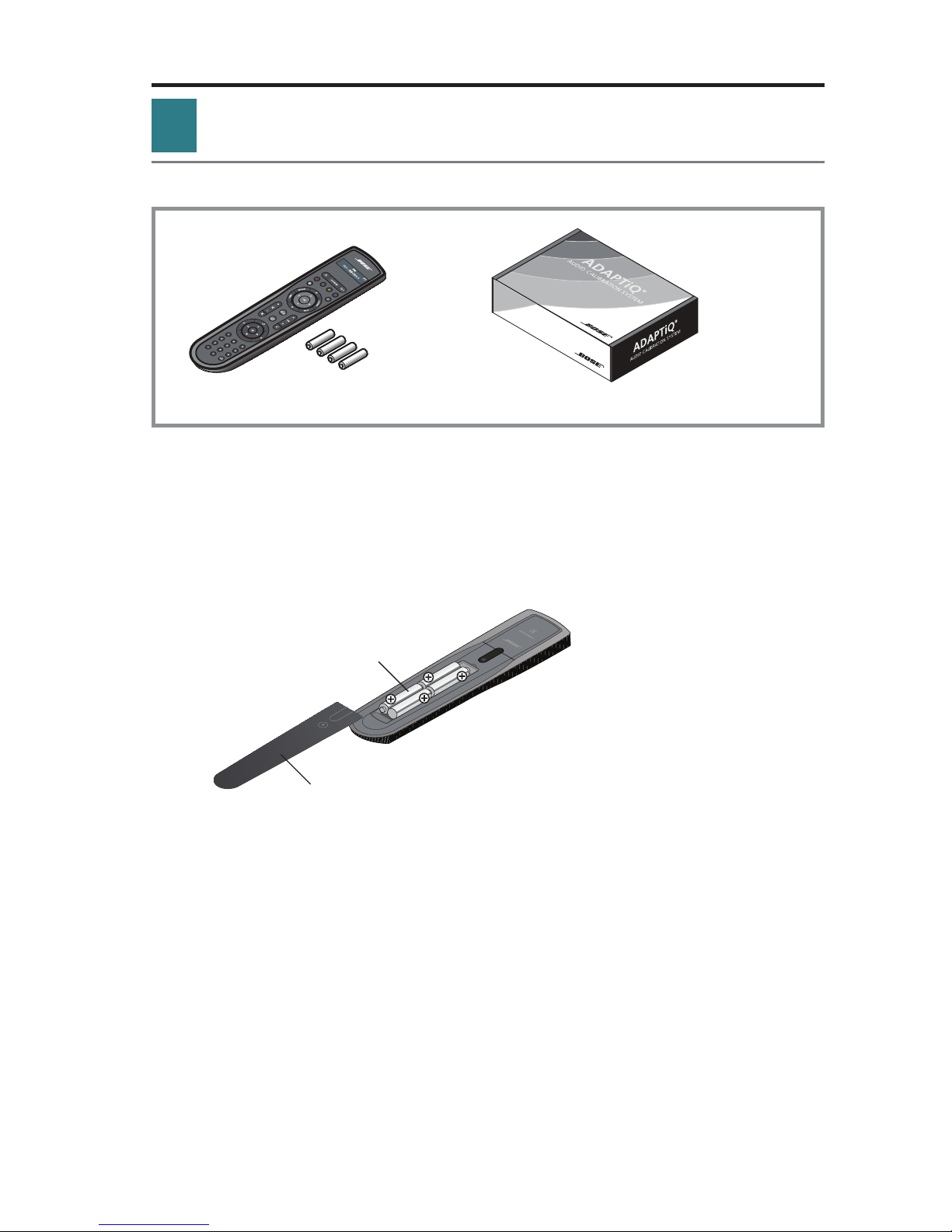
Interactive box
What you need for the following steps:
Remote control with batteries ADAPTiQ® audio calibration headset
IMPORTANT!
Before you start, make sure your speakers and Acoustimass
their final positions.
®
module are in
Do not connect any devices to the control console at this time. The instructions provided on your TV will tell you when to do this.
A. Slide the battery compartment cover off the back of the remote control.
AA (IEC LR6) batteries (4)
Battery compartment cover
B. Install four AA (IEC LR6) batteries, matching the polarity markings (+ and –)
to the markings inside the battery compartment.
C. Slide the battery cover back into place.
English - 17
Page 18

System Setup
D. Press the power button on the control console to turn on your system.
Because the system is in a low power state when in standby, it takes
several seconds to start. When the system status indicator changes
from blinking to steady green, your system is ready to use.
Status indicator
Power button
E. Turn on your TV.
F. Using the remote that came with your TV, change the TV input to the one that
is connected to your LIFESTYLE
®
system.
G. Follow the instructions on your TV. You will be prompted to do the following:
s Select your language.
s Optimize the system audio using the ADAPTiQ
®
audio calibration system.
s Connect audio/video devices to the control console.
s Configure your Bose
®
remote to control your connected devices.
18 - English
Page 19
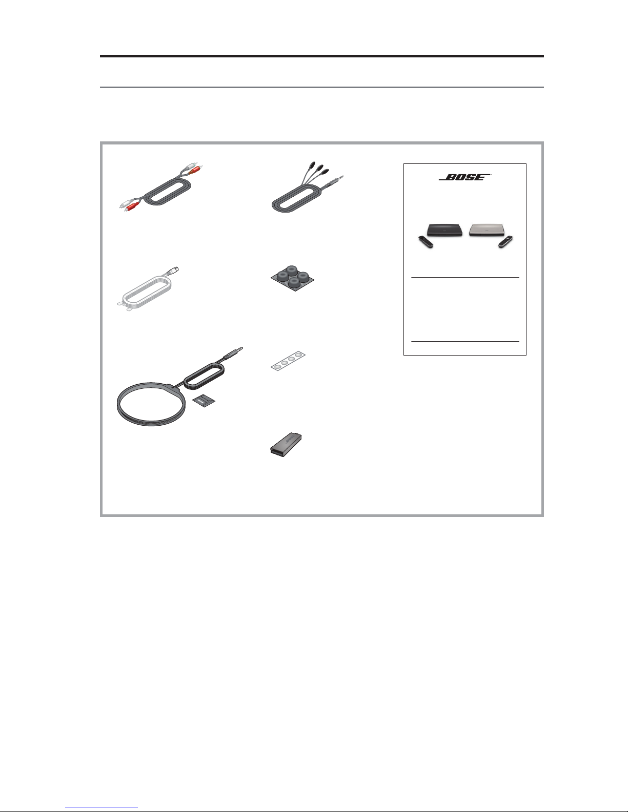
Other Box 4 items
System Setup
The remaining items in Box 4 may or may not be required to set up your
LIFESTYLE
®
system. For more information on using these accessories or
adding other devices to your system at another time, see the operating guide.
Stereo audio cable IR emitter cable
LIFESTYLE® 535/525 series II
home entertainment systems
LIFESTYLE® 235/135 series II
home entertainment systems
LIFESTYLE® 520/510
home theater systems
Operating Guide
Operating guide
FM antenna*
Rubber feet for
Acoustimass module
Rubber feet for front
center speaker
AM antenna*
USB flash drive
(for updating system
software only)
*For LIFESTYLE® 535 and 525 systems only.
English - 19
Page 20
System Setup
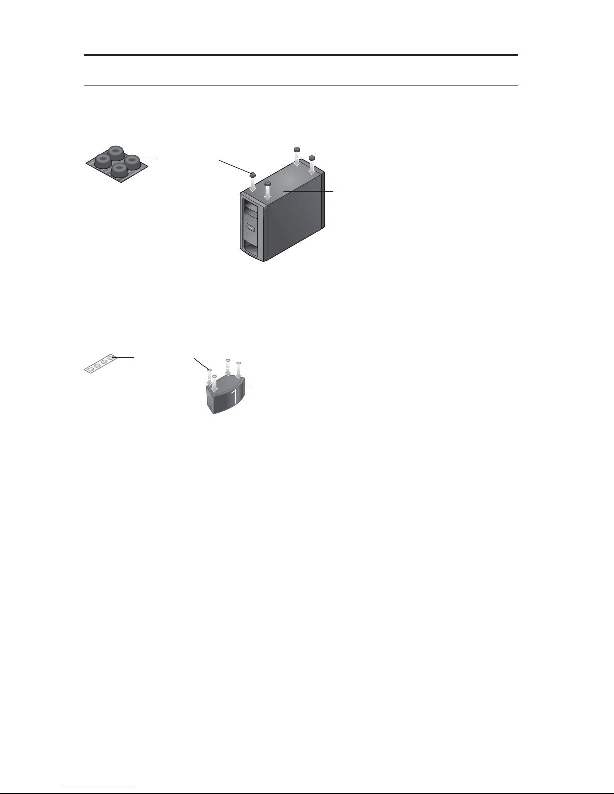
Applying rubber feet
When placing the Acoustimass® module on bare floors, you can attach the
included rubber feet to the bottom of the module for greater stability and
to protect your floor.
Rubber feet
Bottom panel
Vibration can cause speakers to move, particularly if placed on a smooth surface
like glass or highly polished wood. If you are placing the center speaker on such a
surface, you can attach the included rubber feet to the bottom of the speaker for
greater stability.
Rubber feet
Bottom panel
20 - English
Page 21

System Setup
If you have setup problems
If you experience any difficulties during the setup process, such as an unrecognized device remote or a connection error, you can reactivate the interactive setup
mode at any time and correct or change part of your system setup. See “Using the
Setup Mode” in your system operating guide.
For help in trying to resolve any problems, see the troubleshooting table in your
system operating guide.
Contacting customer service
For additional help in solving problems, contact Bose® Customer Service. See the
address sheet included in Box 4.
English - 21
Page 22

©2013 Bose Corporation, The Mountain,
Framingham, MA 01701-9168 USA
AM372631_00 Rev. 00
Page 23

LIFESTYLE®
535/525
series
II
home
LIFESTYLE®
home
LIFESTYLE®
home
Operating
entertainment
235/135
entertainment
520/510
theater
Guide
I
Gula
del
systems
usuario
I
Guide
systems
series
systems
d'utilisation
II
Page 24

Safety
Information
Please
take
Please
system
All
®
properly
Bose
WARNING:
M
~
read this guide
follow
to
time
the
its
enjoy
and
used
be
products
The
uninsulated,
constitute
The
to
WARNING:
To
•
Do
•
as
part
To
•
receptacle.
Do
•
must
lightning
risk
a
exclamation
presence
the
the
reduce
expose
not
on
vases,
system.
the
of
prevent
place
not
with
flash
dangerous
electric
of
point
important
of
Contains
risk
this
near
or
electric
Insert
any
instructions
the
advanced
accordance
in
arrowhead
voltage
shock.
within
small
or
fire
of
apparatus
apparatus.
the
Liquids
shock,
fully.
flame
naked
in
features.
CAUTION: TO
DO NOT REMOVE COVER (OR
USER-SERVICEABLE PARTS INSIDE.
NO
SERVICING TO QUALIFIED PERSONNEL.
REFER
symbol
within
equilateral
an
operating
which
parts
electrical
dripping
to
As
cause
can
the
match
sources,
owner's
this
Please
local,
with
REDUCE THE
within
system
the
triangle,
maintenance
and
may
do
shock,
splashing,
or
any
with
failure
a
blade
wide
such
carefully.
guide
guide
this
save
federal,
state,
RISK OF ELECTRIC SHOCK,
BACK).
equilateral
an
marked
instructions
expose
and
fire
a
line
candles,
that
hazard.
the
do
products,
hazard.
cord
enclosure
as
choking
a
be
not
electronic
and/or
the
of
lighted
as
will
It
future
for
industry
and
triangle
be
may
the
on
in
Not
product
place
not
plug
or
on
help
reference.
regulations.
alerts
sufficient
of
system,
owner's
this
suitable
rain
to
objects
care
use
wide
the
to
the
near
set
you
user
the
intended
is
guide.
children
for
moisture.
or
filled
to
not
slot
apparatus.
operate
and
up
presence
the
to
magnitude
alert
to
under
liquids,
with
liquids
spill
AC
the
of
your
of
to
user
the
age
such
any
into
(mains)
3.
~
~
Notes:
product
The
Where
remain
product
The
boats.
on
product
This
speaker
The
Please
~
~
llllr51!?.ii!El®
(
E
CAUTION:
modifications
no
Make
•
regulatory
Long-term
•
headphones,
using
is
label
plug
mains
the
operable.
readily
be
must
intended
is
and
wire
your
check
dispose
Please
incinerate.
not
Do
Corporation
Bose
relevant
other
complete
compliance,
exposure
located
local
declaration
to
especially
on
appliance
or
indoors.
used
used
be
to
interconnect
building
used
of
hereby
provisions
of
system
the
to
system
and
music
loud
for
bottom
the
coupler
is
It
only
cables
codes
batteries
declares
Directive
of
conformity
accessories.
or
performance.
cause
may
extended
the
or
used
is
designed
neither
the
with
included
correct
the
for
properly,
this
that
1999/5/EC
be
can
hearing
periods.
of
back
the
as
power
with
type
following
product
found
Unauthorized
damage.
product.
the
disconnect
tested
nor
provided.
supply
system
the
and
wire
of
local
any
compliance
in
is
other
all
and
www.Bose.com/compliance.
at:
alterations
best
is
It
device,
outdoors,
use
for
approved
not
are
cable
regulations.
applicable
to
such
required
with
may
extreme
avoid
disconnect
recreation
in
in-wall
for
in-wall
for
essential
the
directive
EU
compromise
volume
shall
device
vehicles,
installation.
installation.
requirements
requirements.
safety,
when
or
and
The
2-
English
Page 25

Safety Information
Important
1.
Read
these
2.
Keep
these
3.
Heed
all
4.
Follow
all
5.
Do
not
use
6.
Clean
only
7.
Do
not
block
8.
Do
not
install
amplifiers)
9.
Do
not
defeat
with
one
blade
or
an
electrician
10.
Protect
the
the
point
11.
Only
use
12.
<I
13.
Unplug
14.
Refer
way,
apparatus,
dropped.
this
all
such
Safety Instructions
instructions.
instructions.
warnings.
instructions.
this
apparatus
with
a
dry
any
ventilation
near
that
produce
the
safety
wider
than
the
third
prong
for
replacement
power
cord
where
they
attachments/accessories
Use
only
with
apparatus.
injury
from
apparatus
servicing
as
to
power-supply
the
apparatus
cloth.
any
heat
heat.
purpose
the
other.
are
from
exit
from
the
When
tip-over
during
qualified
near
water.
openings.
sources
A
provided
of
being
the
cart,
stand,
a
cart
lightning
personnel.
cord
has
been
of
grounding
the
apparatus.
is
or
Install
such
as
the
polarized
for
your
obsolete
walked
on
specified
tripod,
used,
use
storms
Servicing
plug
is
damaged,
exposed
in
accordance
radiators,
type
plug
safety.
outlet.
or
pinched
by
the
bracket,
caution
or
when
to
rain
with
heat
registers,
or
grounding-type
has
two
blades
If
the
provided
particularly
manufacturer.
or
table
when
moving
unused
is
required
liquid
has
or
moisture,
the
manufacturer's
stoves,
plug.
and
plug
at
plugs,
specified
the
for
long
periods
when
the
been
spilled
does
not
instructions.
or
other
A
polarized
a
third
does
by
the
cart/apparatus
apparatus
or
operate
plug
grounding
not
fit
into
convenience
manufacturer,
of
time.
has
objects
normally,
apparatus
your
combination
been
have
(including
has
two
prong.
The
outlet,
receptacles,
or
sold
damaged
fallen
into
or
has
blades
wide
consult
and
with
to
avoid
in
the
been
the
a
Notice
This
equipment
15
of
the
residential
and
used
there
is
no
ful
interference
are
encouraged
•
Reorient
•
Increase
•
Connect
•
Consult
Changes
this
equipment.
These
devices
tion.
They
These
devices
ing
two
conditions:
received,
has
FCC
rules.
installation.
in
accordance
guarantee
to
radio
to
try
or
relocate
the
separation
the
equipment
the
dealer
or
modifications
comply
must
not
be
comply
(
1)
including
interference
been
tested
These
limits
This
equipment
with
that
interference
or
television
to
correct
the
receiving
between
to
or
an
experienced
not
with
FCC
co-located
with
Industry
This
device
and
are
the
instructions,
the
antenna.
the
an
outlet
expressly
and
or
may
that
found
to
comply
designed
generates,
will
reception,
interference
equipment
on
radio/TV
Industry
be
operating
Canada
not
may
to
may
not
occur
which
a
different
approved
,
Canada
license-exempt
cause
cause
undesired
with
the
provide
by
technician
by
in
interference,
reasonable
uses,
and
cause
harmful
in
a
particular
can
be
one
or
more
and
receiver.
circuit
than
for
Bose
Corporation
RF
radiation
conjunction
operation
limits
for
protection
can
radiate
interference
installation.
determined
of
the
following
the
one
to
help.
exposure
with
any
RSS
standard(s).
and
(2)
this
of
the
a
Class
radio
by
which
could
other
device
device.
B
digital
against
frequency
to
radio
If
this
turning
measures:
the
void
the
limits
set
antennas
Operation
must
device,
pursuant
harmful
communications.
equipment
the
equipment
receiver
user's
forth
accept
interference
energy
and,
does
is
connected.
authority
for
the
or
transmitters.
is
subject
any
to
Part
in
if
not
installed
However,
cause
harm-
off
and
on,
to
operate
general
to
interference
the
popula-
follow-
a
you
English- 3
Page 26

Safety
Applicable
Information
for:
only
• LIFESTYLE® 535 and 525 series
home
510
• LIFESTYLE® 520
db
Surround
Digital
Applicable
LIFESTYLE®
~db
Digital
only
235 and 135 series
Audio
and
Manufactured
worldwide
and
U.S.
together
trademarks
are
of
for:
Manufactured
worldwide
other
registered
are
software.
©2010
license
under
patents
registered
Inc.
DTS,
license
under
patents
trademarks
Inc.
DTS,
trademarks
Product
II
issued
home
II
theater
under
issued
includes
home
under
pending.
&
DTS
the
&
Rights
All
entertainment
systems
5,956,674;
#'s:
Patent
U.S.
pending.
&
DTS
&
DTS,
Surround
Digital
software.
©DTS,
entertainment
5,956,674;
#'s:
Patent
U.S.
the
DTS,
trademarks
are
logos
Reserved.
the
DTS
Symbol,
Symbol
systems
5,974,380;
DTS
&
DTS
the
and
Rights
All
Inc.
systems
5,974,380
and
Inc.
DTS,
of
6,487,535
the
and
logos
Reserved.
6,487,535
and
DTS+the
Product
&
symbol
are
Symbol
DTS
includes
other
&
Names and Contents
Name
Part
Mercury Cadmium
X
X
0 0
X
X
hazardous
or
toxic
11363-2006.
hazardous
or
toxic
in
PCBs
parts
Metal
parts
Plastic
Speakers
Cables
Indicates
0:
requirement
Indicates
X:
above
the
limit
Lead
{Pb) {Hg)
this
that
SJIT
in
this
that
requirement
Toxic
of
0
0
0
0
11363-2006.
SJIT
Elements
Hazardous Substances
or
Hazardous Substances and Elements
or
Toxic
Hexavalent
{Cd)
0 0 0 0
0 0
0 0 0 0
0 0 0 0
0 0 0
substance
substance
{CR{VI))
contained
contained
in
in
all
at
of
least
Polybrominated
Biphenyl {PBB)
homogeneous
the
of
one
or
0
materials
homogeneous
the
for
materials
Polybrominated
diphenylether {PBDE)
0
0
limit
the
below
is
part
this
part
this
for
used
is
DOLBY.
III
Designed
The
United
iPhone
Xbox
TiVo
Other
©2013
written
4-
TRUEHD
with
HDMI
terms
States
and
trademark
a
is
trademark
a
is
trademarks
Bose
permission.
English
iPod
Corporation.
Manufactured
trademarks
Technology™
UEI
the
and
other
and
trademarks
are
of
TiVo,
of
property
are
HDMI
countries.
Microsoft
Inc.
of
part
No
Logo
license
under
Lar"ratories.
Dolby
of
Licer
Under
tradf
are
lr
Apple,
of
Corporation.
subsidiaries.
its
or
respective
their
work
this
of
from
from
;
,arks
registered
.,
owners.
be
may
Laboratories.
Dolby
Universal
registered
or
the
in
reproduced,
Electronics
trademarks
other
and
U.S.
modified,
the
and
Dolby
©UEI2000-2011.
Inc.
HDMI
of
countries.
distributed,
double-D
Licensing,
otherwise
or
symbol
in
LLC
used
are
the
without
Page 27

Contents
Introduction
Welcome.............................................................................................................. 7
System features................................................................................................. 7
If
you need help.................................................................................................. 7
I
Controls
Remote Control.................................................................................................. 8
Using
Navigation
Playback
Information
Remote
MORE
Activating
Button
Control
Speaker Array
Acoustimass®
Power
Starting
Turning
Shutting
and Indicators
the
remote....................................................................................... 8
controls................................................................................... 9
controls....................................................................................... 9
display
glow
buttons....................................................................................................
function
Console..................................................................................................
On/Off
your
on
your
down
button..................................................................................
a
MORE
(135
series
Module
Controls
system........................................................................................
TV............................................................................................
your
(535/525/235/135
button
definitions
II
(135
system............................................................................
function........................................................
.....................................................................
systems
series
only)....................................................
II
systems
series
only).....................................
II
systems
only)........
10
10
11
11
11
13
14
14
15
15
15
Operating Your
Selecting a source.............................................................................................
Watching
Using
Using
Tuning
Playing
Selecting
Tuning
Storing
Recalling
Deleting
Optional
TV.......................................................................................................
a
set-top
the
tuner
to
a TV station...............................................................................
audio/video
the
radio (535, 525, 235 and
to
a station.....................................................................................
a
preset
a
a
radio
System Sources
box....................................................................................
in
preset
preset
tuner
your
devices............................................................................
station............................................................................
station.........................................................................
station..........................................................................
TV........................................................................
settings..................................................................
135
series
II
systems
only).........
16
17
17
17
17
18
19
19
19
19
19
19
English-
5
Page 28

Contents
Playing
(535/525/235/135
Using
Changing
content
the
Front
Front
Front
from
front
USB
console inputs................................................
input.............
an iPod
series
or
iPhone
II
systems
....
.........................................................................
Analog A/V input..........................................
HOM
I™
the
input.......
image
view............
......
..........
........
Changing System Options
Using
OPTIONS
the
system
menu..
OPTIONS menu... ..........
.........................................
Changing Your System Setup
UNIFY®
Using
system
the
UNIFY menu................................................................................
overview.................................
Care and Maintenance
only)......... ........
.........
.........
................
..................
...............................
............
................
...........
....................
....
............................................. 26
........................
....
...................
..
.......................... 22
................
.........
.....
............
..........
....
........
...
......... 22
........
...
.....
......
..
....
... 23
.....
20
21
21
22
23
26
Troubleshooting...........................................
Resetting
Pairing
Performing a system
Contacting
Replacing
Cleaning.
Limited
warranty...........
Technical
Licensing
Please complete and retain for your records
the
system.......
the
remote
with
the
software
customer
the
batteries.............................
....
....................
service................................
...
.........................................
.....................
information.
information.....
.............
.........
....
...........
..................
console............
update................
...................................
.........
...................................
....
..................................................................
...
.........................
............
..........
..........
..........
...........
...
...
..............
....
....
...................
.....
....
...................
............
..................
.................
..........
.............
.............
...........
.............
...............
....
........
........................
........
.........
......
......
....
...
..
..
...
..
..
...
..
27
29
29
30
30
30
31
31
32
33
The serial and model number can be found on the bottom panel
LIFESTYLE® model:
Control console serial number:-
Acoustimass® serial number:
Speaker array serial number (135 Series
We
suggest you keep your receipt with this owner's guide.
6 - English
____
--
--------------__________
II
systems):
___
of
the product.
_
_______
_ _
__
_
_
Page 29

Welcome
Introduction
Thank you for choosing a
and easy-to-use system
By now you should
intelligent
ADAPTiQ®
This guide describes your new remote control
system and its connected devices.
integration system and calibrated
audio
have successfully
calibration
Bose®
delivers superior performance for both music and video.
LIFESTYLE®
set up your system using the
the sound for your room using the
system.
System features
Features on all systems
• UNIFY intelligent integration system helps
•
3D video
3D-capable Blu-ray Disc
to
your
•
ADAPTiQ audio
your room
•
RF
remote control
capability
LIFESTYLE®
calibration system that
(requires that you connect a
1M
player,
system)
game
to
console, cable box,
optimizes system performance for
system for your home. This elegant
UNIFY®
and shows you how
easily
add devices
3D-capable
to
operate your
to
your system
TV and a
or
other source
•
HDMI®
•
Video up-conversion
•
Photo viewing using a USB
connectivity
to
1
080p
flash drive
Additional features on 535, 525,
systems only
•
AM/FM radio
•
Back
panel
with iPod and iPhone devices
If
you need help
If you experience any operating
table
on page 27.
helpful tips
please refer
IMPORTANT!
Registering your product enables you
updates
information about new products and
connector for a 30-pin
difficulties,
You
can solve the most common operating
provided there.
to
the included contact sheet.
- Please
to
keep your product performing
If you need additional
register your product right away!
accessory
to
receive notifications
optimally. It also allows
special
235
be sure
offers from Bose.
and 135 series
dock
(not
included) compatible
to
check the troubleshooting
help
or
service for your product,
II
problems
of
system software
us to send you
using the
Please follow
to
register
system software updates.
the instructions on your Product Registration Card
will
not affect your
limited
warranty rights
or
to
your
eligibility to obtain
register. Failure
English- 7
Page 30

Controls
and Indicators
Remote
Using
the
Control
remote
This advanced radio frequency remote works throughout the room.
aim it at the control console.
to
need
selects
Displays
SOURCE
connected devices from the
source
Power-
or off
Color
color-related
connected sources such as
Blu-ray Disc™ players
top
Internet-
accesss on third-party devices
such as
and set-top boxes
Volume
(+)or
volume
-
on your
list
Turns your system on
functions -
functions on
boxes, and for
Activates
Blu-ray Disc
Up/Down
decreases(-) the system
and
TV
Activates
and set-
Teletext
Internet
players
TM
-Increases
rmation
See page
Power-
TV
off
or
on
Teletext-
controls
Navigation
See
MORE
device-specific
information
See
Channel Up/Down -
or previous numbered
channel
on and
page 9
-
page 11.
or
not
do
You
Display
10
Turns your TV
Turns
Controls
Displays additional
on your
preset
-
Teletext
off
-
controls and
TV
Next
Mute -
speakers
Image
video appears
Numeric Keypad -
manual
and settings
Mutes/unmutes system
View-
entry
Changes how
channels
of
Allows
Returns
Channel
Last
last channel
to
Playback Controls
page 9
See
TV Input
inputs on your TV
-
or
Changes
-
preset
-
8-
English
Page 31

Controls
and Indicators
Navigation
OK
highlighted
MENU -
for a connected device
INFO
information
Note:
Displays
-
See "Operating Your System Sources"
controls
-
Selects
Displays
Page Down -
next page
using navigation and playback controls with selected sources.
or
confirms
item
the menu
program
Moves
to
Page Up -
previous page
Left/Right and Up/Down -
Navigation
Moves
GUIDE
or TV program guide, or Blu-ray
Disc
TM
EXIT
from your TV screen
to
-
Displays
player
-
Clears a menu or guide
control
your set-top box
popup menu
on page 16 for more details on
Playback controls
Quick
Replay/Skip
Seek Backward/Rewind
Backward
Shuffle
Stop
Play
Record
Pause
Quick
Seek
Skip/Skip
Forward/Fast Forward
Forward
English - 9
Page 32

Controls
and Indicators
Information
(535/525/235/135
The display provides operating and system status information.
Examples:
Source identification
Radio tuner
90.9 - WBUR90.9
Operating prompt
display
FM
series
P1
II systems only)
Volume
iPod
Remote
Pressing the glow button
buttons (and the display on 535/525/235/135 series
off automatically after several seconds
To
adjust the
Note:
1.
Press and hold the
time for 5 seconds.
2.
Press the up
select Brightness or Contrast.
3.
Press the left
decrease or increase the illumination level.
4.
Press either the
operation.
glow
If
the currently selected source
switch to any other source before making this
adjustment. This prevents unintentionally deleting
a radio preset.
button
~?:-
on the rear of the remote
illumination level
~9--
and
•
or down
~
or right
OK
or
T
...,_
navigation button
~~
to
I
to
prolong battery life.
of the
OK
navigation button
return
display:
is
AM or
buttons at the same
to
FM,
normal
to
to
illuminates
II
systems). The
the remote
light
turns
,,/
-0-
/1'
10-
English
Page 33

Controls
and Indicators
MORE
e
displayed.
buttons
Press the
top
of
depend on the
An
MORE
your
1V
arrow at the right or
button to display
screen for the current source. The functions that appear
selected
source.
left
are available.
When there are more than 13 buttons,
the
displayed
Indicates
the
left.
Move
Activating a
1.
Press the remote
buttons
more buttons to
highlight left.
telling
MORE
MORE
you to
scroll left
button function
button.
additional button functions along
Only 13
of
the
available
buttons can be
the
of the buttons indicates if additional buttons
an
arrow appears either to the right or left
or right
Indicates
right. Move highlight
to
see the other buttons.
more buttons
to
right.
the
of
2.
Press the
left
.....
or right
~
navigation button to
to activate.
3.
Press the remote
OK
button.
Button function definitions
Turns device power on/off.
Displays
channels.
Displays program guide for
next day.
Displays
previous day.
Displays playlist
programs.
Picture-in-picture mode.
a
list
of favorite
program guide for
of recorded
highlight the function you want
Switches your TV to
programming.
Switches between main features
(from
DVD
to VCR, for
a combo device.
Moves
device.
Selects
current source.
Switches tuners
device.
Switches between
a set-top box that provides both.
to
the
"Home"
a repeat option on the
live
state of the
in
a
multi-tuner
TV
and radio on
example)
on
Video on demand.
Switches tuners
device.
in
a
multi-tuner
English-
11
Page 34

Controls
and
Indicators
Button function definitions (continued)
Allows
(Japan only).
you
enter a 3-digit number
to
-
OPTIONS
Displays
See
on page 23.
Accesses the system menu for your
set-top box.
Access the Top Menu (or
on
Accesses
interactive program guide.
Accesses Xbox® functions.
Accesses data broadcast on a tuner
device (Japan
Accesses
Selects
cast
Allows
such as a TiVo® program.
the
"Changing System
Blu-ray Disc™ players.
C,
8,
A,
only).
PlayStation ®
different types of video broad-
only).
(EU
rate certain content,
to
you
menu.
Options"
Menu)
Title
or D functions
functions.
in
an
Blu-ray
Accesses specific
Disc™ players or set-top boxes.
"tools"
on
12-
English
Page 35

Control Console
Controls
and Indicators
G)
System status indicator
Red ...................... System is off (Standby)
Blinking green ..... System is starting
Solid
Amber .................. System is off or turning off, and when charging
®
Front
Used for
®
Headphones output
Accepts stereo headphones with a 3.5 mm stereo
the
@
Control buttons
green .......... System is on and ready
iPhone
AIV
inputs ·
temporarily connecting
volume controls.
0
Power
on/off selection unmute down up menu
Source
Source
in
the
~
Mute/
optional
an
audio/video device such as a camcorder.
~-
Volume Volume
to
use
accessory
n:l+
dock
plug. Volume level is set by
iPod
or
(available from Bose)
Setup
UNIFY®
(page
26)
®
Front USB
Used for viewing photo
Also
used for updating system software.
®
Front HDMI™
Used for
input
input
temporarily connecting
files
from a
an
USB
HDMI
device
including a
device such as a video camera.
digital
camera.
English-
13
Page 36

Controls and
Indicators
Speaker Array (135 series
Status
Off ...................................
Slow blinking
Fast
Solid
Acoustimass®
(135 series
indicator:
orange ......
blinking
red .........................
orange .......
II
Speaker array and Acoustimass® module are connected
Speaker
Speaker array is disconnected and trying
System
array is available
Bose Customer Service)
(Call
error
Module
systems
Status
only)
systems
II
make a wireless
to
only)
connection
connect
to
Status
Solid orange ................... Speaker array and Acoustimass module
Blinks
Slow blinking
Solid
14-
indicator:
every 3 secs ......... Acoustimass module
orange ...... Acoustimass
red .........................
English
is disconnected from speaker array
or speaker array is off (Acoustimass
to
connection
System
error
available
module
(Call
is
Bose Customer Service)
are connected
module
make a
standby)
wireless
Page 37

Power
On/Off
Controls
Starting
To
start your system:
Press
In
several seconds, the system status indicator on the console changes from
blinking
To
start your system and
SOURCE
To
start your system and
Setup
Note:
To
keep energy consumption to a minimum, the system operates
saving mode when it
to
start.
your system
the
Power
to
solid green. The system is
Press the
system and opens the
Press
system and opens the
button on the remote
go
SOURCE
go
the
Setup
is
directly
directly
off. This
to
the
button on the remote control. This starts your
SOURCE
to
the
button on
UNIFY®
is
why the system may take several seconds
or
the console.
now
ready
SOURCE
UNIFY®
the
control console. This starts your
menu on
to
use.
menu:
menu on your TV screen.
menu:
your
TV screen.
in
a power
Turning on your TV
If
you programmed your remote during the initial setup using
the
TV Power
use
•
the
Shutting
C)
Note:
Press the
The system will
If
you decide to access the power
shutdown
onscreen controls.
remote
down your system
Power
is
button on the remote control
that
came with your
button on the remote
shut
down
stopped and you must
automatically after a
UNIFY,
to
turn on your
TV.
or
on the
controls
complete the shutdown using the
for connected devices, automatic
control console.
few
seconds.
TV.
press
Otherwise,
English-
15
Page 38

Operating Your System Sources
source
Selecting
a
SOURCE
The
The menu can
selections,
scroll
Press the
1.
an
up or down
devices on your
menu allows
display a maximum
you
0 selections.
1
of
select
to
arrow appears either at the
see the other items.
to
SOURCE
button on the remote
TV.
your sources and connected devices.
When there are more than 1
the menu telling you
or bottom
top
display
to
Indicates
above. Move
Indicates
below.
Move
of
list
the
selections
more
highlight
more selections
highlight
up.
down.
connected
of
0
to
2. Keep pressing
source you want.
also
can
You
•
a source.
you named a device during the setup process, the assigned name appears
• If
Unnamed devices appear as generic inputs such as
list.
the
in
(HDMI)"
you select a source that
• If
and
reminding you to turn on the source.
Note:
Note:
When listening
prevent the risk
mode
remote
System Options"
The
control each of your devices.
to
to
to
UNIFY®
LIFESTYLE®
the
restore the picture.
SOURCE
use the up
move the highlight down the
to
navigation buttons
down
or
•
T
list
to
select
select
and
"Input 1
(HDMI}."
"Input
intelligent
2
turned off, a message appears on the screen
is
audio sources, the system automatically enters Screensaver
to
screen burn-in.
of
disable the screensaver, see
To
on page 23.
integration system sets up your
one or more of these devices does not respond
If
remote, see "Troubleshooting" on page 27.
Press
any button on the
"Changing
LIFESTYLE®
the
LIFESTYLE
remote
to
16-
English
Page 39

Operating
Your
System Sources
Watching
Your TV may be receiving its program content through a
built
into your
Note:
Since most
point the
TV
TV.
televisions
Bose®
come with an
remote at your
IR
1V
to operate
(infrared) remote, you may need
it.
Using a set-top box
If you connected a cable, satellite,
the
SOURCE
1.
Press
TV programs.
2.
Tune
Using
If
you are using the
1.
Press the remote
2.
Press
3.
Tune
the
to
a station.
the
the
to
a station.
menu
under
remote
tuner
tuner
TV
Input
the name you assigned it during
SOURCE
See
"Tuning
in your
in
your
SOURCE
button
See
"Tuning
or
other
button and select
to
a TV station," below.
set-top
TV
TV
to
receive TV programs:
button
•
and select
to
select
to
a TV station," below.
the
box
the device
TV.
internal
set-top
to
your
the
tuner
box
or
the
TV,
it will appear
setup process.
that
provides
in
your
TV.
tuner
to
in
your
To
return to using other sources,
the input
another source.
Tuning
You
eoo
OeG
for
to
can tune
the
Bose®
system, then press the
a TV station
to
a TV station using any
Enter
dash
the
channel
button
OeO
o
8
e
Press • (channel
Press
the
Last
I
Press
OK
the
GUIDE
buttons
to
number
for
channel
up) or
button
button. Use
select
press the
of
~
a station from
TV Input
SOURCE
the
following
on
the
keypad and press
numbers using a dash
T
(channel
to
tune
the
down)
to
last selected channel.
navigation, page
the
button
methods:
program guide.
•
to
first
button and select
OK.
or
period.
to
change
channels.
up/down,
select
Use the
and
English- 17
Page 40

Operating
Your
System Sources
Playing
During
Blu-ray
inputs 1-5.
If
following controls
the
Disc
you programmed
.,"
t
~
OK
~0
audio/video devices
interactive setup process, you may have connected a CD, DVD,
TM
player,
21
C'G-
..
0
"'
..
~
..
"'
lZ
or
other such device. These are
the
LIFESTYLE® remote for
to
operate the
MENU
GUIDE
INFO
EXIT
..
T
.....
.....
ft
selected
Device menu (if
Blu-ray
Device information
Exit menu
Up one item
Down one item
Move
Move right
Select
Disc
left
the
device.
available)
player
typically
device, you can use the
pop-up menu
connected
or
system setup menu
DVR,
to
2S
SZ
.....
II
•
•
~
~
~
~
$
Next page, channel,
Previous page,
Play
Pause
Stop
Record
Fast forward
Fast rewind or search reverse
Quick skip
Quick
Shuffle
replay
mode
or
or
skip forward
or
or
disc
channel,
search forward
skip backward
or disc
18-
English
Page 41

Operating Your System Sources
Selecting
(535, 525,
1. Press the SOURCE button.
2. Keep pressing the SOURCE button to select
Tuning
to
the
235
radio
and 135 series II systems only)
a station
• Press
frequency band.
Or,
• Press ~ (seek next)
next/previous strong station.
111-1
(increase) or ~ (decrease)
or~
(seek previous) to find the
Storing a preset station
The built-in radio tuner can store up to 25
1. Tune
2. For presets 1-9, press and hold the number
to
a radio station.
OK
button to store the station
in
FM
and 25 AM preset stations.
the next available preset.
FM
or AM
to
key.
For 1 0-25, press and hold the
in
the SOURCE list.
tune up or down the
Preset number
Recalling a preset station
Press
down) to go
preset.
I
_.
(channel up) or T (channel
to
the next or previous
0 0 8 For quick access to
0 e G presets 1-9, press the
0
8 number key of the preset.
0
ooe
Deleting a preset station
1.
Recall the preset station you want to delete.
2.
Press and hold the
display.
Optional radio
1. Press the MORE button • and select OPTIONS.
2. From the OPTIONS menu
OK
tuner
button until the preset number disappears from the
settings
(see
page 24 for details) you can select:
• Current Station: Allow Stereo, Stereo Off
•
RDS:
On, Off
English-
19
Page 42

Operating Your
System Sources
Playing
content
from an iPod or iPhone
(535, 525, 235, and 135 series II
audio and video from
Your LIFESTYLE®
30-pin
the
Your iPod or iPhone menus and content appear on the
shown
accessory
the
in
system can
dock
following example.
play
included) available from Bose.
(not
"Now Playing"
The
track appears on the right.
systems
or iPhone
iPod
an
your screen as
of
side
left
only)
using
following controls
The
3
..,.,
"'
;-
~
OK
•
~0
..
!l
"c:.
'o
"<
"'
...
MENU
sz
"'
.....
II
• Stop
~
operate your connected
menu
to
(press and hold
level
video, pause
level. If playing
level
available
are
Up one menu
level). If playing
Up one page
Down one page
Up one menu item (press and
Down one menu item (press and
Up one menu
to
Down one menu
Down one menu level
Play
Pause
Next track or audio bookmark
iPod.
menu
top
to
go
to
menu
and return
hold
hold to scroll quickly)
video, pause and return
to
scroll quickly)
to
101111111
...
....
$ Shuffle
English
20-
Previous track
Fast forward
Fast rewind
mode
audio bookmark
or
Page 43

Operating Your System Sources
Using
The front
input. These inputs appear in the
(Front)
connecting devices such as digital
Front
Your
LIFESTYLE®
USB
storage device.
When selecting the
followed
the
of
the
only when a device is connected. These inputs are provided for temporarily
USB
by
single
front
console provides analog
console inputs
SOURCE
input
system can
USB
image files. Selecting
display
source, folders
AN
inputs
menu
cameras and video cameras.
photo
files
appear at the
a folder displays
as
(.jpg
plus
a USB and
AN
(Front),
or
.jpeg format only)
top
of
the list
its contents.
an
USB,
on the
HDMI®
and HDMI
from a
left
Use the
.,"
~
•
~.co
following
"
QG-
~
"'
"
~
..
..
sz
controls for viewing digital
Up
one menu item (press and hold
Down one menu item (press and
Up
one
folder level,
MENU
sz
EXIT
II
•
folders
Up
folders
Down one
Down one
slideshow
Up
Down nine items
Exit slideshow and return
Play slideshow
Pause slideshow
Exit slideshow and return
Next image
(if viewing a slideshow)
one folder level,
(if viewing a slideshow)
folder level
folder level
(if a photo
nine items
of
photos.
hold
or
exit and return
or
exit and return
(if a
folder
file is highlighted)
to
highlighted folder
to
is highlighted),
browsing
browsing
to
repeat)
to
to
to
folders
folders
repeat)
browsing
browsing
or
play
Previous image
English -
21
Page 44

Operating
Your
System Sources
Front
You can use this input for devices that have
outputs. The
You need
Analog
use the
to
Front HOM I
You can use this input for devices that have an
control
not
does
on the device
Changing
A/V
Bose®
input
a device connected
itself
the
Press the image view
choices. Continue
Your TV picture
Note:
input
composite
remote
controls
or
does
on the device
the remote that
not
control
to
came
a device connected
itself
this input. You need
with it.
image view
button
press this
to
change
will
When
display
video cannot be changed when watching
displaying
a menu
of
to
momentarily
video, the
30
video formatting choices. The shape
video and
the remote that came with it.
or
HDMI output. The Bose remote
display
button
a menu
highlight
to
after you
Image View button does not
left/right
this input.
to
use the
to
video formatting
of
your
select
video.
30
audio
controls
choice.
a format.
of
the
Normal
Auto-Wide
Stretch 1
Stretch
2
Zoom
Gray Bars
Leaves
Fills width
Stretches video image
Stretches the edges
than the center portion
Enlarges
navigation
on your screen).
Places vertical gray bars on the left and right
standard-definition video image.
original
the
video image unchanged.
the screen
of
video image (press the
buttons
without
evenly
the
of
of
vertically
to
video image much more
the image.
cropping any content.
from the center.
up/down
offset the image
of
a
22-
English
Page 45

Changing
System Options
Using
The number of items appearing
currently selected.
1. Press the remote
2.
Press the
the remote
shown
the
left
OK
in
the
system
MORE
~
or right
button to display the OPTIONS
following
button
~
example.
OPTIONS
in
the
OPTIONS
•.
navigation button and highlight OPTIONS.
menu
menu depends
menu for the current source
on
which source
is
Press
as
3.
Press the up
want to change.
4.
Press the
5.
Press the remote
OPTIONS
Factory settings are
• or down
left
-411111
menu
Option
Sound
(Not available
on 235 series
or 135 series
systems)
Current
(Not available
on 520 or 510
systems)
II
II
Station
T
navigation button and highlight the option you
or right
EXIT
in
_Available
Original ...................... Plays stereo audio when stereo audio is received
Recommended .........
Alternative ................. Plays 5-channel audio when either stereo or
Enhanced Mono ......... Plays simulated surround sound when monaural
Allow
Stereo Off .................. Changes the current station
~
navigation button and select the setting.
button when done.
bold
type.
Settings
Stereo ..............
from the source
Plays 5-channel audio whether 2- or 5-channel
audio is received from the source
5-channel audio is received from the source
audio is received from the source
Allows stereo sound from the current stereo
radio station
to
mono, which can
help when tuning
to
a weak radio station
FM
English- 23
Page 46

Changing System Options
Option Available Settings
ADS
available
(Not
520 or 510
on
systems)
Game Mode
Audio
Compression
Audio Track
Volume Offset
...............................
On
.............................. No ADS information on the remote
Off
.............................. Reduces video processing and
On
Off ..............................
............................... No change
Off
Enhance
Dialog
Displays
Normal
Enhances sound output so you can hear movie
.........
dialogs
Smart
Volume
............. Reduces the range
ADS information on the remote
performance
audio track
to
distinctly
more
volume levels
of
soundtrack so the difference between
outbursts and soft sounds is
loud
noticeable
Track 1 .......................
Track 2 ........................
Both Tracks ................
Selects track 1 from an
with
multiple
audio tracks
Selects track 2 from an
multiple
with
Selects
audio tracks
tracks 1 and 2 from
external
external
stream
Not
Available
.............. Automatically selected
when
received
Increases the
to
sources
(0
volume level
0)
1
of
the
selected
source relative
delay
less
audio stream
audio stream
external
an
one track is
only
to
a movie
in
extremely
audio
other
Source Overscan
only)
(2D
System Bass
only)
(3D
AN
only)
Treble
Sync
only)
Sync
System
2DAN
(2D
3D
3D
(3D
Power Down
the current video
..............................
On
Applies video overscan
to
source
.............................
Off
overscan
an
level:
30
Note:
When a
of
Adjusts bass
Adjusts
treble level:
Adjusts the audio delay
-2
Normal
to
to
Sets the 3D image
Automatic .................
Side by side ................
Top and bottom .........
Adjusts the audio delay
Normal
to
-2
Normal
to
.......................
Video source unaffected
source is playing, "Not Available"
value.
+6 {After
Normal
to
-9
Normal
to
-14
Normal
to
-9
Normal
to
-14
synchronize audio with the 2D video:
to
to
+ 14 (No ADAPTiQ
to
+6 {after
to
+ 14 (no ADAPTiQ
to
is
ADAPTiQ®
ADAPTiQ®
+5
display correctly with the appropriate 3D
to
Sets the correct 3D image format
Selects the side by side format
Selects the
synchronize audio with the 3D video
to
top/bottom
format
+ 1 0
System shuts down without presenting the
displayed instead
calibration)
calibration)
calibration)
calibration)
glasses
automatically
Power Down Menu
Power Down Menu ..... System presents the Power Down Menu when
shutting down
Screen saver
English
24-
On ......
......
Off
Displays a screensaver after 20 minutes
playing audio-only
Disables
screensaver mode
sources
no user activity when
of
Page 47

Changing
System
Options
Option Available
Rear
Speakers
(Not
available
on 235 series
or
135 series
systems)
Center
(Not
on 235 series
or
systems)
Speakers
(Not
on 235 series
or
systems)
Volume
TV
Speaker
available
135 series
available
135 series
on TV
Speakers
II
II
II
II
II
II
Adjusts
(-1
Note:
Adjusts
speakers:
Note:
Stereo
Front
Surround
On
Off
On ......
Off
the
0
to
Normal
This option
or
the
This option
(2)
(3)
...... Enables
indicator
...... Prevents
indicator
Sends
affected
pressing
.....
Sends HDMI audio
............ Activates
Sailings
volume level
to
+6)
is
unavailable
Front
(3).
volume level
-8
to
Normal
is
unavailable
.......... Activates
{5} ..... Activates
the
system
on your TV
the
display
HOM
I™
audio
by
plugging
Mute
or
of
the
rear speakers
if the Speakers option
of
the
front center speaker
to
+8
if the Speakers option
only
front
left
only
front
left,
all front and rear speakers
to
display
of
the
to
your
headphones into
Volume
to
the LIFESTYLE® system speakers
the
volume level
TV (audio from
on
the
relative
relative
and right speakers
center, and right speakers
volume level
meter
the
the
control console
remote)
to
front speakers:
is
set to
Stereo
to
other
is
set to
Stereo
meter and
and
mute
TV is
not
(2)
(2)
mute
or
by
Video
Automatic
(20
Output
only)
Off
Changes
video
as options)
Note:
Enabled ......... The system,
Disabled
Note:
the
resolution (Standard
signal
sent
to
your
TV
When a
matches the resolution
then shows the
not change
The system
no
longer
setting does not affect this function.
30
source
automatically-set output
resolutions while
automatically
(no user interaction)
......... The system
will automatically turn off after
longer
hear audio or see video from a video source or you no
hear audio
from
Definition/720p/1 080i/1 080p)
(only
settings
is
playing, the output resolution always
of the connected
a
including
turns
itself
will
not
turn
an
audio source. The 4-hour Automatic
30
the
source
off
itself
supported
30
resolution,
is
playing.
Bose®
link
after
four
off
automatically
15
by
your TV appear
source. Video Output
and you can-
second zone,
hours
minutes after you
of
of
inactivity
the
Off
English- 25
Page 48

Changing Your
System Setup
UNifY®
UNIFY intelligent integration system guides you through the initial process
The
system
setting up and configuring your system.
inputs, and program the
After completing the initial setup, you can use the
overview
LIFESTYLE®
It helps you choose the right cables
remote to operate your connected devices.
UNIFY
system at any time
change your system setup and configuration.
Using
display
To
the
the
control console.
you want and
Menu item
Resume initial
setup
Restart initial setup
Reconnect
Acoustimass®
(135 series
systems only)
Language Change the language
ADAPTiQ®
II
UNIFY
UNIFY
follow
menu on your
Using the navigation buttons on the remote, select
the instructions on the screen.
What
your initial setup is incomplete, you can return
If
process at the last completed event.
your initial setup is incomplete, you can start the
If
process from the beginning.
Follow
the Acoustimass module.
the ADAPTiQ audio calibration process. After ADAPTiQ has been
Start
run, this menu item
menu
press the
TV,
you can
the onscreen instructions
do
the onscreen display.
of
allows
you
Setup
button on the front of the
the function
the UNIFY
to
UNIFY setup
reconnect the speaker array with
to
enable ADAPTiQ.
disable
to
or
of
and
to
setup
TV setup
Source
Add a new device
Update
Teach mode
Exit
setup For sources connected
UNIFY
After your TV is connected to the console, you can:
control your TV
Program the
•
Manually enter remote control
•
Replace your TV
•
Add, change,
•
Change the name
•
Program your remote
•
Manually enter remote
•
Remove the
•
or
Add
•
After your initial setup is complete, you can add another device
accessory
perform a system software update (see
to
Used
software update"
This item is used
Closes the
LIFESTYLE®
remove the TV audio connection
or
of
device
change the type of audio or video connection
your system.
to
on page
send
to
UNIFY
menu and returns you
remote
Input 1-5
to
the device
control the device and add
to
controiiR
30
codes
IR
to
device codes
IR
the control console, you can:
of
device codes
"Performing
for more information).
program a learning remote.
to
the last source selected.
to
theIR
emitter
a system
or
26-
English
Page 49

Troubleshooting
Care
and Maintenance
Problem
The system is not
responding
operation
remote
The Bose remote does
not control a device
added during the initial
setup
The video connection
from a connected source
is
less
System doesn't
anything
No sound
to
initial
of
my
Bose®
than optimum
do
I
What to do
•
Make sure the control console is turned on.
•
Check
or need replacement.
page 30.
•
Reset the system.
•
Press any remote key and watch the system status indicator
on the control console.
see
and
•
Try
the control console. Select the device options and
onscreen instructions
•
Your system may need a software update.
system software
To
change a video connection, press the
control console
onscreen instructions.
•
Make sure the AC power cord is inserted securely into the
power supply.
•
Make sure the
are fully plugged
•
(135 series
plugged into a
• Select
•
Reset the system.
•
Make sure the Acoustimass module is plugged into a
(mains) outlet.
•
(135 series
plugged into a
• Increase
•
Press the Mute button and make sure your system is not
muted.
• Check the input connections on the control console. Make
sure that you have selected the right source.
•
Make sure that the audio input cable is firmly plugged into the
Audio
and the other end is firmly seated into the Media Center
connector on the Acoustimass module.
•
(135 series
cable is firmly plugged into the Audio Out
Bose
seated into the Audio
• (135 series
of
router, another wireless device,
away from the system.
•
For radio operation, connect the FM and AM antennas.
•
Reset the system.
to
see if the remote batteries are
See "Replacing the
See "Resetting the
It
"Pairing
follow the procedure.
setting up the device again. Press the
Out
link)
wireless
the remote with the console"
update" on page 30.
and select the device setup options.
Acoustimass® module and the power supply
into a
II
systems
live AC (mains) outlet.
a connected device from the
See "Resetting
II
systems only) Make sure the speaker array is
live
AC (mains) outlet.
the volume.
connector (not Bose
II
systems only) Make sure that the audio input
on the control console
II
systems only) Try moving any possible sources
interference, such as a wireless computer network
See "Resetting
should blink with each press.
to
set up the device again.
live
AC (mains)
only)
Make sure the speaker array is
SOURCE
the
link)
on the
and the other end is firmly
In
connector on the speaker array.
or
a microwave oven, further
the
installed
batteries" on
system"
Setup
outlet.
system"
system"
on page 29.
on page 29
Setup
connector (not
button on
See "Performing a
button on the
menu.
on page 29.
control
on page 29.
correctly
If
follow the
Follow
live
console
not,
the
AC
English- 27
Page 50

Care and Maintenance
Problem
Sound quality has Press the Setup button on the control console and select the
changed and speaker
array status indicator instructions.
is blinking orange (135
systems only).
series
TV
remote commands the
(135 series
only)
Intermittent bass
(135 series
only)
II
does not respond to
systems that
II
systems is orange and not blinking.
II
Sound is impaired by
a loud hum or buzz, other electrical devices
which may be electrical
nature
in
What to
"Reconnect
• Make sure the speaker array is not blocking
For details on the location
•
owner's guide that came with your
Check that the status indicator on the Acoustimass® module
•
• If
-Check
- Press the Setup button on the control console and select
-Try
Contact
signals, and
do
Acoustimass" menu item.
Change the position
TV.
theIR
the speaker array status indicator is blinking orange:
AC
the "Reconnect Acoustimass" menu item.
onscreen instructions.
such as a wireless computer network router, another
wireless device, or a microwave oven, further away from
the system.
sensor is not blocked.
that the Acoustimass module is plugged into a
wall outlet and the status indicator is glowing orange.
moving any possible sources
Bose®
Customer Service
in
obtain possible remedies.
to
of
the TV's
of
the room may be creating unwanted
Follow the onscreen
theIR
and speaker array so
TV
the
sensor, refer to the
IR
TV.
Follow the
wireless interference,
of
determine if and how
to
sensor on
live
Make sure antennas are connected properly.
Radio does not work
sound is distorted
FM
Picture is blurry when
content
viewing
Sound is distorted • Make sure the audio input cable is not damaged and the
30
•
from the control
em)
inches
• Move AM antenna at least
console and Acoustimass module.
Adjust antenna position
•
Make sure the AM antenna is
•
• Move antennas farther from control console,
electronic equipment.
• Select another station.
coverage for some stations.
Adjust antenna position
•
• Fully
• If
•
• If
•
•
•
extend the
30
your
turned on.
Try changing the
the problem persists, make sure the speaker array is not
blocking
TV
For details on the location
owner's guide that came with your
connections are secure on both ends.
Reduce the volume output
connected
(135 series
the trim and
Acoustimass module.
theIR
and speaker array so that the
FM
glasses are
30
sensor on the
the control console.
to
systems only) Remove the protective film from
II
on the speaker array and the front
grille
20
improve reception.
to
in
may be
You
reduce interference.
to
antenna.
the active type, make sure they are
of
system option
TV.
the TV's
of
level
(50
upright position.
an
TV,
of
area
an
in
a different setting.
to
Change the position
R sensor is not blocked.
I
sensor, refer to the
IR
TV.
from any external devices
or other
weak signal
of
of
the
the
English
28-
Page 51

Care
and Maintenance
Problem
No sound from a
connected device
No
TV
picture, but audio
is heard
A
connected device
does
not respond
consistently
commands.
Intermittent audio drop- Contact Bose Customer Service
outs heard on coaxial cable that can be used for the coaxial digital audio connection.
digital audio inputs
Resetting
1.
Press and
or until
to
remote console.
the
system
hold
the system status indicator
The system status indicator on the control console changes to
Wbaltodo
•
Check the connections.
• If using a coaxial or optical audio connection, make sure you
have not made both types of connections
on the control console.
•
Make sure that device is turned on.
•
Refer
to
the owner's manual that came with the device.
•
Check the
the video source.
•
Make sure video cables are securely connected.
Try
connecting the
console. For guidance, press the
.
instructions.
the
Power
button
TV
Select
video input selection. Make sure it is correct for
included
the device options and
0
on the control
on
the control console
external
Setup
to
console for
lA
request a composite video
to
the same input
emitter to the control
button on the control
follow
the onscreen
5
seconds
changes to red.
red
when the
system shuts down.
2.
Release
The system status indicator changes
the
Power
button
0
on
the
control console
to
blinking green and then solid green
to
restart the system.
when the system is on and ready to use.
3.
If
you still
cannot operate the system using the remote, try the next procedure
to pair the remote with the control console.
Pairing
You
may need to perform this procedure if you are replacing
troubleshooting instructions recommend
1.
Make sure your system is on.
the
remote
with
the
console
it.
If
not, press the
Power
a remote or
button
0
on the
control console.
2.
Hold
3.
the remote
Press and
hold
close to the
both the
Mute
control console.
button
~
on
the
control console and the
button on the remote at the same time for five seconds. The system status
indicator blinks
4.
Press any remote button and verify that the system status indicator on the
when pairing
is
complete.
control console blinks with each button press.
if
OK
English- 29
Page 52

Care and Maintenance
Performing a system software update
System software updates may be
downloaded
Press the
1.
UNIFY® menu.
2. Using the remote navigation buttons,
Follow
3.
Note:
To
the
over the
Setup
the instructions on the screen.
make sure your Bose remote
control console while
Internet
button on the front
available periodically
to the USB drive
is
being updated.
is
it
included
the control console
of
select Update.
updated,
hold
from Bose and can be
with your system.
the remote near the front of
Contacting customer service
solving problems, contact Bose® Customer Service. See the
additional help
For
address sheet
Replacing
Replace all four batteries when you notice a marked decrease
response of your remote
remote
display.
in
included
the
in the carton.
batteries
when you see the
control,
or
battery icon on the
low
display
to
the range
in
the
or
Low battery
icon
Slide
1.
2.
3. Install
the battery compartment cover off the back
(IEC-LR6)
AA
Remove the old
markings(+
batteries
batteries.
four new AA
and-)
the remote
of
(4)
Battery compartment cover
(IEC-LR6) 1.5V batteries, matching the polarity
to the markings inside the battery compartment.
control.
Slide the battery cover back into
4.
30-
English
place.
Page 53

Cleaning
You
can
wipe
the outside surfaces using a soft
vacuum the speaker
grilles.
CAUTIONS:
•
DO
NOT
use
solvents, chemicals,
•
DO
NOT allow liquids
to
spill
or objects
Limited warranty
or sprays for
to
drop into any openings.
Care and Maintenance
dry
cloth. You can
cleaning.
also lightly
Your LIFESTYLE®
tration card
and
mail
for
details. Please
it
to
Bose. Failure
system is covered
be
sure
to
do
so
by
a limited warranty. See
to
fill
out
the information section on the card
will
not
affect
your
your
product
limited warranty.
regis-
English-
31
Page 54

Care
and Maintenance
Technical
Remote
Frequency: 2.4 GHz
Range: 33
Control console
AC input: 1
DC output:
Acoustimass®
235 series II
USA/Canada: 1
International:
Dual voltage:
Acoustimass®
AC input power: 1
control
(1
ft
00-240Vrv
12V=-=-=
information
m)
0
power
35W Max.
module
systems
00-120Vf\..; 50/60 Hz
220-240Vrv
00-120/220-240Vrv
1
module
00-240Vrv
Speaker array rating
(6.1
mW@
m)
00-240Vrv
AC input power: 1
Wireless
Output
Range:
connection
power: 5
ft
20
supply
50/60
rating
rating
for
rating
Hz,
for
50/60
for
50/60
LIFESTYLE®
50/60
for
2400-2480
rating
,OA)
(1
1.0A
LIFESTYLE®
350W
350W
Hz
50/60
Hz
LIFESTYLE®
150W
Hz
135 series
Hz 60W
LIFESTYLE®
MHz
535, 525,
350W
135 series
systems
II
135 series
520, 510
·
systems
II
only
systems
II
and
only
only
32-
English
Page 55

Care and Maintenance
Licensing information
This product contains one or more free or open source software programs originating from third parties and distributed as part of the STLinux
www.stlinux.com/download for further details. This free and open source software
is subject
General Public License, or other different and/or additional copyright licenses,
notices, and disclaimers.
refer to the specific terms
provided
product's control console.
USB
To
download "licenses. pdf" from your product's control console:
1.
Press and hold the
the
2.
Insert
the
3.
Press the
This download process should be completed within 30
remove the
to
the terms
to
you
in
port and a software program that can view .pdf files.
System Information screen.
a
USB drive (there should be one included
USB
input on the front
OK
USB
of
the GNU General Public License, GNU Library/Lesser
To
understand your rights under these licenses, please
of
the licenses, notices, and disclaimers, which
an
electronic file, named "licenses.pdf,"
To
read this file, you will
Setup
button on the remote control to copy the file to the
drive.
button
of
on
the front
the control console.
need a computer with a
of
the control console to display
in
software package. Visit
are
located within the
your system package) into
USB
drive.
seconds.
You
may then
4.
To
read the file
port, navigate
ware program that can view .pdf files.
To
receive a copy
included
Mailstop 6A2, Bose Corporation, The Mountain, Framingham, MA
Bose Corporation
covering the cost
shipping and handling.
disclaimers are reproduced and available with such source code. This offer
is
valid for a period
product by Bose Corporation.
in
this product, please mail your written request to: Licensing Manager,
"licenses.pdf,"
to
the USB
of
the source code for the open source software programs
will
distribute such source code to you on a disc for a charge
of
performing such distribution, such as the cost of media,
All
of
the above referenced licenses, notices, and
of
three
(3)
plug the
root directory, and open "licenses. pdf"
years
following the date
USB drive into a computer with a
01701-9168.
of
distribution of this
with a soft-
USB
English- 33
Page 56

372636-001 0
Better
©2013 Bose Corporation, The Mountain,
Framingham, MA
AM372636
sound
Rev.
through
01701-9168
00
research®
USA
Page 57

0
0
0
0
©2008
Bose
Corporation, The Mountain, Framingham, MA
01701-9168
USA
AM252749
Rev.02
BOSE®
Page 58

BOSE
OUR
We
take
great
pride in designing each
accuracy
the
to
avoid
While
In
addition, we use
techniques
Our
for
th
th
at continually
musical
musical sounds
flashy
those sounds may be
performance
sounds such
only
to
ensure
as
closely
the
possible in
as
as
those associated
initially
the
highest-quality
reliability
reputation rests on our steadfast pursuit
e home,
the
automobile,
gives rise
and businesses.
to
new
COMMITMENT
of
our products
the
possible
attractive
and
technologies
to
long life
When you purchase any product from Bose,
compe
titive
products for
musical
accuracy.
TO
YOU
with
the
goal
of
providing
price range
those
with
to
the
parts
and
of
our products.
of
this
At
Bose,
of
that
product.
of
the
original performance. And we strive
accentuated bass and/or treble
novice, they are
the
latest
policy
in music and
we
are
not
real
assembly
entertainment
committed
for improving sound reproduction.
we
encourage you
We
believe
th
at
th
to
compare
is process
will
the
We
strive
and are
and
to
inve s
it
.
as
to
not
quality control
ting
we
do,
enhance your
highest-
reproduce
frequencies.
enduring.
systems
in research
to
appreciation
With
best
wishes from
of
th
e product you
all
of
sel
ect.
us
at
Bose for many years
of
enjoyable listening.
lllllllllllllllllll
251001
BO
St
COR
P
OR?.T!ON,
THE
t'v10UNTA
iN, FRAMINGHAM,
CJ
5
t
--
1A
Ol701
-·
Cl!68
U.
S.A.
TE
L.:
508
.
87Sl7330
FAX:
508
.
766
.
7543
WVv'VV.BOSE.
.
COt¥1
C.>
Z~
Page 59

Bose
Corporation
USA
Bose Corporation, The Mountain
Framingham, MA 01701-9168
1-800-901-0195
Phone hours Weekdays 8:30 a.m.
Saturdays 9 a.m. to 3 p.m.
owners.Bose.com
ET
(Eastern Time):
to
8 p.m.
Canada
Bose Ltd., 1-35 East Beaver Creek Road
Richmond Hill, Ontario L4B 1 B3
1-800-465-2673
Phone hours Weekdays 9 a.m. to 5 p.m.
www.Bose.ca
ET
(Eastern Time):
Australia
Bose Pty Limited, Unit
Newington NSW 2127
TEL
612 8737 9999
312
Holker Street
FAX
612 8737 9924
Belgique/Belgie
Bose
N.V.,
B-3700 Tongeren
TEL
Limesweg 2
012-390800
FAX
012-390840
China
Bose Electronics (Shanghai) Ltd
2203-2305
1 038 West Nanjing Road
MeiLongzhen Plaza
Shanghai200041
Peoples Republic of China
TEL 86-22-62713000 ext 162
FAX
Dan
Bose A/S, lndustrivej 7
2605 Bmndby
TEL
22F,
West Gate Tower
86-21-62713008
mark
04343-7777
FAX
04343-7818
Deutschland
Bose GmbH, Max-Pianck-StraBe 36d
D-61381 F riedrichsdorf
TEL
06172-71040
www.Bose.de
FAX
06172-710419
France
Bose S.A.S.
12
rue
de T emara
78100 Saint Germain
TEL
01
30
www. Bosefrance. fr
61
63 63
en
Laye
FAX
01
30
61
63 88
India
Bose Corporation India Private Limited
Floor,
4th
Shriram Bhartiya Kala Kendra,
1 Copernicus Marg
New Delhi, India 1 00
TEL
+91
11
FAX +91
2307 3825 I 3826 I 3827
11
2307 3823
001
Ireland
Bose GP
Castleblayney Road
Carrickmacross, Co Monaghan
TEL(042)9671500 FAX(042)9671501
www.Bose.ie
ltalia
Bose S.p.A., Via della Magliana 876
00148 Roma
TEL 06 60 292 292
www.Bose.it
FAX
06 60 292 119
Japan
Bose
K.K.
Shibuya
28-3 Maruyama-cho
Shibuya-ku, Tokyo 150-0044
TEL +81-3-5489-0955
www.Bose.co.jp
YT
Building
FAX
+81-3-5489-1
Mexico
Bose de Mexico
Paseo de las Palmas
Despacho 204
Lomas de Chapultepec
C.P..
11000, Mexico
TEL +52
TEL +52
FAX
(55)
(55)
+52
52 02 35 45
52 02
(55)
52 02 37 28
S.
de
# 405
D.F.,
41
R.L.
Mexico
95
de C.V.
Nederland
Bose
B.V.,
Nijverheidstraat 8
GE
1135
TEL 0299-390111
consumenteninfo@Bose.com
www.Bose.nl
Edam
FAX
0299-3901 09
Norge
Bose A/S, Lerkeveien 58
2209 Kongsvinger
TEL 62 82 15 60
FAX
62 82 15 69
Osterreich
Bose Ges.m.b.H., Vienna Business Park
Wienerbergstrasse 7
A-11 00 Vienna
TEL 01-60404340
www
.Bose.at
(1
O.OG)
FAX
01-604043423
Schweiz
Bose AG, Hauptstrasse 134
4450 Sissach
TEL 061-9757733
www.Bose.ch
FAX
061-97577 44
Sverige
Bose A/S, Johannefredsgatan 4
S-43153 Molndal
TEL 031-878850
FAX
031-274891
United Kingdom
Bose Limited
1 Ambley Green
Gillingham Business Park
Gillingham, Kent ME8 ONJ
TEL 0870-7
www
41
.Bose.co.uk
-4500
FAX
0870-7 41-4545
World Wide Web
www.Bose.com
www. Boseeurope.com
owners. Bose.com
041
328733
·001 0
BOSE
Better sound
©20
10 Bose Corporation, The Mountain, Framingham,
through
AM328733_00 C_008492
research®
MA
01701-9168 USA
®
Page 60

Important
1.
Read these instructions
before using this product.
2.
Keep these instructions
3.
Heed all warnings
owner's guide.
4.
Follow all instructions.
5.
Do not use this apparatus
not use this
kitchen sink, laundry tub, in a
a swimming pool,
moisture are present.
6.
Clean only with dry
Bose®
wall outlet before cleaning.
7.
Do not block any ventilation openings. Install
in accordance with
instructions-
product
the product in a position and location that will
interfere with its proper ventilation. For example,
do
not place
surface
Do
not
case
through its ventilation openings.
8.
Do not install
Safety
product
Corporation. Unplug this product from
and
to
the
that
may
put
it in a built-in system, such as a
or
a cabinet
Instructions
-for
all components
-for
future reference.
-on
the
product
near
near a bathtub, washbowl,
wet
or
anywhere else that water
cloth-
the
To ensure reliable operation
protect
near
it
product
block
the
that
may
any
and
manufacturer's
from overheating,
on a bed
ventilation openings.
keep air from flowing
heat
and in
water
basement, near
as directed
, sofa,
or
sources,
such as radiators, heat registers, stoves
or
other apparatus (including amplifiers)
that produce heat.
9.
Do not
polarized
ized plug has
than
two
wide blade
for your safety.
fit into your outlet, consult
replacement
10.
Protect
on or pinched, particularly
venience receptacles, and
they exit from
11.
Only use attachments/accessories specified
defeat
the
the
safety purpose of
or
grounding-type plug. A polar-
two
blades with one wider
the
other. A grounding-type plug has
blades and a third grounding prong.
or
the
third prong
If
tr-.e
provided plug does
of
the
obsolete outlet.
the
power cord from being walked
the
apparatus.
are
provided
an
electrician
at
plugs, con-
the
point where
by the manufacturer.
12.
Use only with
bracket
manufacturer
the
cart, stand, tripod,
or
table specified by
or
sold with
the
the
apparatus. When a cart is used,
use caution
cart/apparatus combination
when
moving
the
to
avoid injury from tip-over.
13.
Unplug this apparatus during lightning
or
storms
of
time
when unused
-to
prevent damage
for
long periods
to
this product.
the
- Do
or
by
the
of
the
put
not
similar
book-
The
not
for
14.
Refer all servicing to qualified service
personnel. Servicing is required when
the
apparatus has been damaged in any way:
such as power-supply cord
liquid has been spilled
into the apparatus;
to
exposed
normally,
to
service this
covers may
other hazards. Please call Bose
authorized service center near you.
15.
To
prevent risk
rain
or
has been dropped - Do
product
expose
the
or
moisture, does not operate
yourself. Opening
you
of
fire
overloading wall outlets, extension cords,
or
plug is damaged;
or
objects have fallen
apparatus has been
not
or
to
dangerous voltages
to
be referred
or
electric shock, avoid
attempt
removing
or
to
an
or
integral convenience receptacles.
16.
Do not
as they
short-out parts
electric shock.
17.
See
let
objects or liquids
may
touch
dangerous voltage points
that
could result in a fire
enter
the
or
product -
product enclosure for safety related
or
markings.
lnfonnation
generate
If
applicable, this equipment has been tested and found
to
comply with the limits for a Class B digital device,
to
pursuant
designed
harmful interference in a residential installation. This
equipment generates, uses, and can radiate radio
frequency energy and,
accordance with the instructions, may cause harmful
interference
is no guarantee that interference will
particular installation. If this equipment does cause
harmful interference
which can be determined
off
and on, you are encouraged
interference
• Reorient
• Increase the separation between the equipment
and receiver.
• Connect the equipment
than the one
• Consult the dealer
technician
Note:
remote control could void
this
equipme
This product complies with the Canadian ICES-003 Class
B specifications.
Part 15
to
provide reasonable protection against
to
by
or
for
Unaut
horiz ed modificati
nt.
about
electrical
of
the
if
radio communications. However, this
to
radio
one
or
more
relocate the receiving antenna.
to
which the receiver is connected.
or
help.
products
that
noise
FCC rules. These limits are
not installed and used
not
occur in a
or
television reception,
by
turning the equipment
to
try
to
correct the
of
the following measures:
to
an outlet
an experienced
on
th
e user's authority
on
radionv
of the
receiver or radio
a different circuit
to
in
operate
Page 61

Important
18.
Use proper power
a proper
instructions
19.
Avoid power
installing an outside antenna system
touching
them
near overhead
power
such circuits
20.
Ground
antenna
product,
grounded. This will
voltage surges
Section
NFPA
proper grounding
structure, grounding
discharge unit, size
location
grounding electrodes, and requirements
ground electrode. Refer
illustration on this page.
Safety
Instructions
sources-
power
source,
or
as marked on
lines-
power
may
circuits,
all
or
be
81
No
.
of
lines
be
fatal.
power
nor
or
power
outdoor antennas -
cable
sure
and
0
of
the
70
provides information with respect
antenna-discharge unit, connection
as
described
the
Use extreme care when
or
circuits, as
Do
not
install external antennas
lines
or
other electric light
where an antenna can
lines.
system is connected
the
antenna
provide
built-up static charges.
National Electrical
of
the mast
of
of
grounding conductors,
or
some
and
the
lead-in wire
to
the
antenna grounding
Plug
the
product
in
the
operating
product.
to
keep from
contact
If
an external
cable system is
protection against
supporting
fall
to
this
Code
to
an antenna
for
with
into
ANSI/
to
to
the
into
or
Antenna
Example
Code,
ANSI/NFPA
Note
This reminder is provided
installer's attention
that
provides guidelines for proper grounding.
lar,
it specifies that the cable ground
to
the
grounding system
point
of
grounding
of
antenna grounding as
70.
111
...--+-(NEC
~--Groundin
~+rr----(NE
Ground
...-
-P
ower se
ele
ctrode
(
NEC
to
CATV system
to
call
the CATV system
to
Article 820-40
of
the
building, as close
cable entry as is practical.
per
ART
installer
National Electrical
Antenna
clamps
rvic
system
250,
of
shall
discharge unit
Section 810-20)
g
C
Section 810-21)
e grounding
Part
H)
the
NEG (of USA)
In
be
connected
conductors
particu-
to
the
11111111111111111
255805
ROSE
Better
SOU1d
©2007
Bos
Framingham,
255805
e Corporation, The Mountain,
AM
through
MA
01701-9168 USA
Re
v.0
3
research
®
®
Page 62

._.
.
-
,_......
·
-----
~
~
~
( USB
This
USB
flash
require
Please
Esta
updating
see
unidad
actualizar
de
usuario.
i
nformaci6n.
Cette
de
USB
necessaire
decrit
dans
Updates.Bose.com
Dette
hvis
USB-flashdrev
dit
system
drive
is
provided,
as
described
Updates.Bose.com
flash
el
sistema
Consulte
de
le
USB
est
fournie,
mettre
guide
se
tal
Updates.Bose.com
a
jour
d'utilisation.
pour
medfelger
krcever
opdatering
betjeningsvejledningen.
pa
Updates.Bose.com.
p
should
in
the
for
more
suministra
como
plus
Du
se
describe
pour
le
cas
votre
systeme
Consultez
d'informations.
og
kan
finde
your
Operating
information.
por
si
si
ou
il
kan
bruges,
som
beskrevet
flere
system
Guide.
es
necesario
en
Ia
Gula
desea
sera
com
le
mas
it
me
site
i
oplysninger
Dieses
lhres
beschrieben
finden
Questa
utilizzata
cosi
informazioni,
Deze
geval
zoals
Raadpleeg
Anvand
systemet
i
anvandarhandboken.
USB-Fiash-Laufwerk
System
wie
in
der
mitgeliefert.
Sie
unita
come
unter
qualora
descritto
Updates.Bose.com.
USB
flash
fosse
nel
visitare
USB-stick
er
een
beschreven
wordt
update
in
van
de
Updates.Bose.com
den
medfoljande
kraver
uppdatering
Updates.Bose.com.
wird
fur
die
Aktualisierung
Bedienungsanleitung
Weitere
viene
necessaro
Manuale
lnformationen
fornita
per
aggiornare
d'uso.
essere
Per
ulteriori
Updates.Bose.com.
meegeleverd
het
systeem
voor
nodig
het
is
bedieningshandleiding.
voor
USB-enheten
enligt
Mer
information
meer
beskrivning
informatie.
om
finns
il
sistema
i
Updates.Bose.com
BOSE®
02010
Bose
Corporation.
C_008333
AM318542_00
Page 63

.c
Q
·-
.I:
Cl')
..
...
-
m
11
.
-
"iil!c
&VCD
E
N
• •
~=
-
c:
·-CD
me
..
c:
a
U~CD
a•
c:
-.a
·
c •
Ci
~ma
·-
~
a-
u-
.a
J!
CD·-
>-_
Ez
~
.
•
a
•
...
CD
""1:1
c
~
._
""1:1
U
...
0
~
w
::::.
-
IC
c
:l:
rn
:5
u..
UJ
:::l
c
'
•
-
®
.CHAI
A·tl~"!~~
{!1~011
A:~A-tl~
~-~~~-~--~M·~~~Mmn~5~.
~~m~u&mfi~~o~~••·••~
Updates.Bose.como
USB
[[}2.1-
~~E
AlA~
Updates.Bose.com-1-
E.2.f-OI~~
~r:tiOI
EAI
-~~~~--~~~-~~~-~-ft~~·
~~m~uM~ft~~o~~•m·••~
'Y
o
~
~
~'71'7'~~,
Updates.Bose.com
L:O)USB77
~~~LHAi21
-iRWL..lQ.
!t~'!l--t=IAI2..
flfFjj'.{
~,,~
~a-~ntc~A.Tb.r
tc~.g-O)tc~t~f\j}l
Updates.Bose.com~~~
~~'
Updates.Bose.com
Y/7-
'
L 't"l,'*9o
L
BOSE'
Corporation.
C2010
Bose
t--b'~fl:c"/j.?
~~,~~l,'Z
Z
ttt!l,
<
'o
C_008333
AM318542_00
Page 64

pamitt
Ta
gdyby
USB
system
wymagaf
flash
dostaraona
jest
aktualizacJi
wypadek,
na
zogdnie
z
oplsem
lnstrukcji
w
adresem
pod
Jarjestelman
varalta,
kuvatulla
Updates.
USB
az
Ezt
esetre,
az
arra
lefrtak
szerint
latogasson
LL~~!f1j;j"i~
r;t1~~"i::v1;t~f,~EJn1"il;\11~
~t'U
a111~U~EJ~~L~~L~3.!
obstugi.
Updates.Bose.com.
mukana
jarjestelma
etta
tavalla.
Bose.com.
flash
ha
frissfteni
az
el
{t~j;ja\11;t~a1~~Ufl"itU~;£h'ID'WLj;ij;J"i::UU!JfN
USB
"
Witcej
toimitetaan
lisatietoja
meghajt6t
rendszert
a
szeretne.
Updates.Bose.com
informacji
paivitettava
on
osoitteessa
on
keszlilekhez
a
Hasznalati
a
Tovabbi
hhr;~fl~
mozna
USB-muistitikku
webhelyre.
Updates.Bose.com
znalezc
silta
kayttoohjeessa
mellekeljuk
utmutat6ban
informaci6kert
Ail~o~~
~~Oil
:AlAil~
USB
IIJ-2.~
~.!I!.~
~~
~2.HAI
A~
AI
Updates.Bose.com~
c2.~011::j
OlE
Cil
~
~
AI
~
~~o~~AI.2..
'21-LHAi~l
c~.
-g{LI
R
Page 65

Warranty
information
inside
Register
your product now
Contiene
informaciOn
sabre
Ia
garantfa
Registre
su
producto
ahora
Renseignements
sur
Ia
garantie
a
l'interieur
Enregistrez
votre produit
des
maintenant
Page 66

Registre
su
producto:
Conozca
toda
Ia
gama
de
servicios
que
su
garantia
le
ofrece.
Registrarse
en
lfnea
es
facil y rapido.
Global.
Bose.com/register
Enlace
directo
para
registrarse:
www.register.Bose.eu
(Europa)
www.Bose.com/register
(EE.UU.,
Puerto
Rico
www.Bose.eom.au/warranty
(Australia)
www.Bose.ca/register
(Canada)
www.Bose.eo.nz/warranty
(Nueva
Zelanda)
e
Islas
Vfrgenes
de
EE.
UU.)
Envie
cualquier
correspondencia
en
relacion
con
informacion
de
productos o los
servicios
de
Ia
Garantia
limitada a Ia
sede
corporativa
de
Ia
empresa
en:
Registro
del
producto
Bose
Corporation
The
Mountain
PO
Box
9168
Framingham,
MA
01701-9168
EE.UU.
A
quien
cubre:
Esta
garantia
se
extiende
unicamente
al
comprador
final
original
o a
Ia
persona
que
reciba
el
producto
como
regalo y no
se
extendeni a cualquier
otra
persona o beneficiario.
Que
se
cubre/Por
cuanto
tiemoo:
A
menos
que
un
pertodo
de
garantia
diferente
se
explicite
en
Ia
Guia
del
usuario
provista
con
su
producto
Bose~
por
un
periodo
de 1 ano
(2
anos
en
Ia
UE.)
[5
alios
para
altavoces
no
electncos
incorporados
en
el
producto] a partir
de ~ fecha
de
Ia
compra
minorista
por
parte
del
usuario
final
original,
Bose
garant0J
que
este
producto,
cuando
se
le
entrega
en
su
paquete
original y en
nueva
condid6n,
por
parte
de
un
revendedor
autorizado
por
Bose y es
utilizado
en
condiciones
normales,
no
tiene
defectos
de
fabncaci6n,
de
materia~
ni
de
producci6n.
Que
es
lo
que
no
se
cubre:
Esta
garantia
no
cubre
defectos
ocasklnados
por
pnicticas
de
uso o mantenimiento
incorrectas o no
razonables,
el
incumplimiento
de
las
instrucciones
de
uso:
accidentes;
humedad
exce~va:
insectos;
rayos;
subidas
de
tensi6n;
conexion
a
vo~aje
incorrecto:
alteraciones
o
mod1f~ciones
no
autorizadas
del
producto
original;
danos
causados
por
embalaje
o
proceso
de
envio
inapropiado:
perdida,
dano
o
alteracion
de
Ia
informacion
guardada;
danos
ocasionados
por
el
uso
con
productos
que
no
sean
de
Bcse;
productos
que
requieren
de
modificacion
o
adaptackin
para
permitir
que
se
utilicen
en
cualquier
pais
Iuera
del
pais
para
el
que
fueron
diseriados,
1-800-736-5076
(EE.UU.)
1-508-766-1000
(INTL)
Es
posible
que
se
ap/iquen
cargos
par
Ia
1/amada.
Tenga a mana
el
mJmero
de
serie
cuando
rea/ice
Ia
1/amada.
Los
propietarios
que
vivan
fuera
de
los
Estados
Unidos
deben
revisar
Ia
Gufa
del
usuario
o ira
Globai.Bose.
com
para
encontrar
Ia
direcci6n
mas
cercana.
fabricados,
aprobados
y/o
autorizados, o reparaci6n
de
productos
danados
por
estas
modificaciones:
y
productos
adquiridos
de
vendedores
no
autorizados.
Que
haremos:
Durante
el
periodo
de
garantia
repararemos
o
sustituiremos, a nuestra
discrecion,
las
partes
defectuosas
en
un
periodo
razonable
de
tiempo y sin
cargo
utilizando
repuestos
nuevos o rehabilitada.
Que
es
lo
que
no
haremos:
Pagar
cargos
por
envio,
seguros o transporte
del
producto
de
usted a nosotros,
tasas
de
importacion
o
impuestos.
Que
debe
hacer
para
obtener
el
servicio
dela
Garantia
limitada:
Devuewa
el
producto
con
el
comprobante
de
compra
emitido
por
un
vendedor
autorizado
de
Bcse,
real~ando
los
siguientes
pasos:
1 .
Contactese
con
Ia
compania
Bcse
en
su
pais/
region
(visite
Globai.Bose.com
para
obtener
Informacion
de
contacto
en
su
pais/region)
a
fin
de
obtener
instrucciones
especfficas
sabre
devolucion y envio;
2.
Rotule y envie
el
producto,
con
flete
pago, a Ia
direccion
de
Ia
compariia
Bose
en
su
pais;
y
3.
Coloque
cualquier
numero
de
autorizad6n
para
~
devolucion
que
sea
necesario
en
forma
vsible y en
Ia
parte
exterior
del
paquete.
Los
paquetes
que
no
tengan
un
numero
de
autorizacion
de
devolucion,
cuando
sea
necesario,
seran
rechazados.
Otras
condiciones:
LAS
DISPOSICIONES
DE
ESTA
GARANT[/>.
LIMITADA
REEMPLAZAN
CUALOUIER
OTRA
GARANT[/>.,
VA
SEA
EXPRESA 0 IMPLiCrTA,
ESCRrTA U ORAL,
INCLUVENDO
CUALQUIER
GARANTIA
DE
COMERCIABILIDAD 0 ADECUACION A UN
FIN
PARTICULAR.
LA
RESPONSABILIDAD
MAxiMA
DE
BOSE
CORPORATION
NO
PUEDE
EXCEDER
EL
PRECIO
DE
COMPRA
REAL
QUE
USTED
PAGO
POR
EL
PRODUCTO.
BAJO
NINGUNA
CIRCUNSTANCIA
SERA
BOSE
RESPONSABL£
POR
LA
PtRDIDA,
DANO
0
AL
TERACION
DE
INFORMACION
GUARDADA
0
POR
DANOS
ESPECIALES,
INCIDENTALES,
EN
CONSECUENCIA 0 INDIRECTOS
CUALQUIERA
SEA
LA
CAUSA
DE
LOS
MISMOS,
INCLUYENOO
SIN
LIMITACION,
EL
REEMPLAZO
DE
EOUIPOS
V
PROPIEDADES V CUALQUIER
COSTO
DE
RECUPERACIDN,
PROGRAMACION 0 REPRODUCQDN
DE
CUALQUIER
PROGRAMA 0 INFORMACION
GUARDADA 0 UTLIZADA
CON
SU
PRODUCTO
BOSE.
Esta
garantia
se
anula
en
caso
de
que
Ia
etiqueta
con
el
numero
de
serie
haya
sido
quffada o danada.
Otros
derechos
legales:
Esta
garantia
limitada
le
otorga
derechos
legales
especificos y es
posible
que
tambien
se
le
otorguen
otros
derechos
que
vartan
segun
los
estados
o
paises.
Algunos
lugares
no
permiten
limrtacooes
en
garantias
rmplicitas o Ia
exclusion o limitacion
por
danos
secundarios o resultantes,
por
lo
que
es
posible
que
las
limitaciones o exclusiones
anteriores
no
se
apliquen a usted
*En
caso
de
que
no
registre
su
producto
no
se
veran
afectados
sus
derechos
de
garantfa
limitada.
Enregistrez
votre
produit:
Renseignez-vous
sur
Ia
gamme
complete
de
services
offerts
dans
le
cadre
de
notre
garantie.
L'enregistrement
en
ligne
est
simple
et
rapide.
Globai.Bose.com/register
Liens
directs
vers
les
sites
d'enregistrement
:
www.register.Bose.eu
(Europe)
www.Bose.com/register
(Etats-Unis,
Puerto
Rico
www.Bose.eom.au/warranty
(Australie)
www.Bose.ca/register
(Canada)
www.Bose.eo.nz/warranty
(Nouvelle-Zelande)
et
ites
Vierges
des
Etats-Unis)
Pour
toute
correspondance
relevant
d'une
demande
de
renseignements
au
sujet
de
nos
produits
ou
de
nos
services
de
garantie
limitlie,
veuillez
nous
ecrire a notre
siege
social, a l'adresse
suivante
:
Enregistrement
de
produits
Bose
Corporation
The
Mountain
PO
Box
9168
1-800-736-5076
(Etats-Unis)
1-508-766-1000
(international)
Des
frais
peuvent s 'appliquer.
Veuillez a voir
en
main
votre
numero
de
serie
Iars
de
l'appel.
Framingham,
MA
01701-9168
Etats-Unis
Si
vous
residez
hors
des
Etats-Unis,
consultezle
guide
de
l'utilisateur
au
le
Globai.Bose.com
pour
obtenir
l'adresse
postale
Ia
plus
proche.
Benlificiaire
:
La
presente
garantie
est
uniquement
valable
pour
le
premier
acheteur
ou
Ia
personne
ayant
recu
le
produit
en
cadeau
et
ne
peut
en
aucun
cas
etre
etendue
ou
transferee a une
autre
personne.
Obiel
et
duree
de
Ia
garantie
:
A
moins
qu'une
dunie
differente
ne
soil
indiqwie
dans
le
guide
de
l'utilisateur
foumi
avec
le
produrt,
Bcse
•
garantit
pendant
une
perklde
d'un
an
(deux
ans
dans
I'UE)
[cinq
ans
pour
tout
haut-pareur
non
amplffie
integre
au
produit], a partir
de
Ia
date
d'achat
au
detail
par
le
premier
acheteur,
que
le
produit
est
libre
de
tout
vice
de
materiaux
et
de
fabrication
klrsqu'il
est
livre a l'etat
neut,
dans
son
emballage
d'origine
et
par
un
detaillant
autorise
Bcse,
et
qu'il
est
utilise
dans
des
conditions
normales.
Exclusions
:
La
presente
garantie
ne
couvre
pas : les
defauts
ou
dommages
resultant
d'une
utilisation
ou
d'un
entretien
inapproprie
ou
inccrrect,
du
non-respect
des
directwes
d'utilisation,
d'un
accident,
d'une
humidrte
excessive,
de
Ia
presence
d'insectes,
de
Ia
foudre,
d'une
pointe
de
courant
electrique,
d'un
raccordement a un
courant
electrique
d'une
tension
incorrecte,
d'une
alteration
ou
d'une
modnicatkJn
du
produit,
de
procedures
d'emballage
ou
d'expedition
inappropriees;
Ia
perte,
!'alteration
ou
Ia
deteroration
de
donnees
informatiques:
les
dommages
causes
par
!'utilisation
avec
un
produit
d'une
marque
autre
que
Bose;
les
modifications
ou
adaptations
effectuees
au
produit
pour
qu'il
soil
utilisable
dans
un
pays
autre
que
celui
pour
lequel
il a lite
conc;u,
fabrique,
approuve
eVou
autorise,
de
meme
que ~ reparation
d'un
produrt
endommage
par
ces
modifications;
les
produits
achetes
aupres
d'un
detail~nt
roo
agree
Notre
engauement
:
Au
cours
de
~
p8riode
de
garantie, a notre
seule
discretion,
nous
reparerons
ou
remplacerons
lOUie
piece
derectueuse
dans
un
delai
raisomable,
sans
frais
utill<lant
nouve
ou
renove
les
parties
de
remp~cement.
Frais
exclus
:
La
garantie
ne
ccuvre
pas
le
paiement
des
lrais
d'explidrtion,
d'assurance
et
de
transport
du
produit
vers
notre
adresse,
ainsi
que
de
toutes
taxes
et
de
tous
droits
d'importation
ou
autres
Conditions
de
l'oblention
des
services
de
garantie
limi!Ee
reparation
:
Expediez-nous
le
produit,
accompagne
de
Ia
preuve
d'achat
d'origine
d'un
detaillant
Bose
autorise,
en
suivant
les
directwes
ci-dessous
·
1
Communiquez
avec
l'entrte
Bcse
de
votre
pays
ou
regkJn
(consurtez
le
site
Globai.Bcse.com
pour
connaitre
les
coordonnees
de
Bcse
dans
votre
pays
ou
region)
pour
obtenir
les
instructions
de
retour
et
d'expedition
particulieres:
Etiquetez
et
expediez
le
produit,
en
port
paye,
a
l'adresse
foumie
par
l'entite
Bose
de
votre
pays
ou
regkJn;
et
lnscrivez
de
tar;on
Ires
~sible
sur
l'exterieur
de
l'emballage
tout
numero
d'autorisatkln
de
retour
necessaire.
Un
envoi
qui
ne
comporte
pas
de
numero
d'autorisation
de
retour
klrsque
celui-ci
est
requis
sera
refuse.
Autres
conditions
:
LES
CONDITIONS
DE
LA
PRESNTE
GARANTIE
LIMITEE
REMPLACENT
TOUTE
AUTRE
GARANTIE,
EXPRESSE
OU
IMPLICITE.
EXPRIMEE
PAR
tCRrf
OU
ORALEMENT, V COMPRIS
TOUTE
GARANTE
DE
QUALJTt
MARCHANDE
OU
D'ADAPTATION
A
UN
USAGE
PARTICULIER.
LA
RESPONSABILITE
MAXIMALE
DE
BOSE
CORPORATION
EQUIVAUT
AU
PRIX
PAVE
PAR
LE
CONSOMMATEUR A L'ACHAT
DU
PRODUIT.
BOSE
NE
PEUT
EN
AUCUN
CAS
ETRE
TENUE
RESPONSABLE
DE
LA
PERTE,
DE
L'ALTERATION
OU
DE
LA
DETERIOATION
DE
DONNEES
INFORMATIQUES,
Nl
DE
DOMMAGES
PARTICULIERS,
ACCESSOIRES
OU
INDIRECTS,
QUELLE
QU'EN
SOIT
LA
CAUSE, V COMPRIS,
SANS
RESTRICTION,
L£
REMPLACEMENT
D'EOUIPEMENT
ET
DE
BIENS
ET
TOUS
FRAIS
DE
RECUPERATION,
DE
PROGRAMMATION
OU DE
REPRODUCTION
DE
TOUT
PROGRAMME
OU
DE
TOUTES
DONNEES
ENREGISTRES
DANS
LE
PRODUIT
BOSE
OU
UTIUSES
AVEC
CELUI-CI.
La
presente
garantie
est
annulee
si
!'etiquette
portant
le
numero
de
serie
est
retiree
ou
alteree.
Autres
droits
:
La
presente
garantie
limitee
vous
confere
des
droits
particuliers
selon
Ia
loi;
vous
pouvez
aussi
beneficier
d'autres
droits
qui
varient
selon
votre
pays
ou
region
de
residence.
Certains
territ01res
ne
permettant
pas
Ia
limitation
des
garanties
impl1cites
ou
I'
exclusion
ou
Ia
limitation
des
dommages
indirects
ou
accessoires,
il
est
done
possible
que
les
l1mites
ou
exclusions
ci-dessus
ne
s'appliquent
pas a vous.
*Le
non-enregistrement
du
produit
n'affecte
aucunement
vas
droits
en
vertu
de
Ia
garantie
limitee.
Page 67

Register
your
product:
Learn
about
the
full
Registering
range
of
online
services
is
quick
your
and
Globai.Bose.com/register
To
link
directly
www.register.Bose.eu
www.Bose.com/register
www
.Bose.com.au/warranty
Send
any
to
our
corporate
Product
Bose
Corporation
The
Mountain
PO
Box
Framingham,
to
registration:
(Europe)
correspondence
headquarters
Registration
9168
MA
01701-9168
(US,
PR
(Australia)
regarding
&
USVQ
at:
USA
product
information
warranty
easy!
www.Bose.ca/register
www.Bose.eo.nz/warranty
or
Limited
Warranty
1-800-736-5076
1-508-766-1
Please
Owners
Guide
have
living
or
Global.
000
your
outside
Bose.
(US)
(INTL)
serial
the
com
(Canada)
(New
services
Charges
number
available
United
for
the
provides.
Zealand)
may
apply.
when
you
call.
States
should
check
the
Owner's
nearest
mailing
address.
LIMITED
Who
is
covered:
Th
is
warranty
end-use
product
other
person
What
is
Unless
Owner's
for
a
period
non
-
powered
this
product]
original
product,
original
and
used
in
manufacturing,
What
is
This
warranty
improper
failure
excess
connections
alteration
damages
procedures;
stored
Bose
products;
or
adaptation
other
than
is
purchaser
as
a
gift,
or
transferee
covered/For
a
different
Guide
provided
of
1
year
speakers
from
end-use
purchaser,
when
delivered
packaging,
in
normal
materials
not
covered:
does
or
unreasonable
to
follow
moisture;
to
improper
or
modification
caused
by
loss
data;
damages
product
to
enable
the
country
WARRANTY
extended
and
warranty
the
from
conditions
not
operating
insects;
inadequate
of,
or
the
shall
not
.
how
period
with
(2
years
that
may
date
of
Bose
to
you
a
Bose
,
and
cover
li
ghtning
voltage
damage
caused
that
it
to
for
which
only
to
the
person
receiving
be
extended
long:
is
stated
your
Bose
®
EU)
[5
years
be
incorporated
retail
purchase
warrants
in
new
condition,
authorized
is
free
from
any
workmanship.
defects
resulting
use
or
maintenance
instructions;
;
power
supply;
unauthorized
of
original
condition;
packing
or
to
or
corruption
by
use
with
requires
operate
modification
in
any
it
was
original
product,
for
that
reseller
defects
accident;
surges;
shipping
country
designed
to
in
by
from
non-
manufactured,
of
the
products
any
What
During
repair
the
parts)
time
any
What
into
Pay
the
from
this
in
What
Service:
Return
authorized
procedures:
1.
;
2.
of
3.
,
approved
products
damaged
purchased
we
will
the
warranty
or
replace
any
defective
and
free
of
we
will
shipping,
you
Contact
region
information
return
Label
address
country;
Place
prominently
not
required,
to
us
vou
must
product,
Bose
the
(visit
and
and
provided
and
any
bearing
will
insurance
,
shipping
ship
necessary
and/or
by
from
unauthorized
do:
period,
(using
new
or
parts
within
charge.
not
do:
or
or
any
import
do
to
obtain
with
proof
dealer,
Bose
organization
Globai.Bose
in
your
country/region)
instructions;
the
product,
by
the
return
on
the
outside
a
return
authorization
be
refused.
authorized,
these
modifications
dealers.
we
will,
at
our
refurbished
a
reasonable
transportation
fees,
dut
i
es
Umited
of
purchase
using
the
in
your
.
com
for
Bose
freight
prepaid,
Bose
organization
authorization
of
the
carton
number,
,
rr
or
repair
;
and
sole
option,
replacement
period
of
charges
and
taxes.
Warranty
from
an
following
country/
contact
for
specific
to
the
in
your
number
.
Cartons
where
Other
conditions:
THE
PROVISIONS
ARE
IN
LIEU
OF
WHETHER
OR
MERCHANT
PURPOSE
LIABILITY
PURCHASE
IN
NO
DAMAGE
OR
OR
CAUSED
REPLACEMENT
AND
OR
STORED
This
number
Other
This
and
state
do
exclusion
damages,
not
EXPRESSED
ORAL,
INCLUDING
ABILITY
.
BOSE
SHALL
PRICE
PAID
EVENT
SHALL
TO
OR
CORRUPTION
FOR
SPECIAL,
INDIRECT
INCLUDING
OF
ANY
COSTS
OF
REPRODUCING
IN
OR
USED
warranty
limited
you
not
apply
has
legal
to
allow
is
been
rights:
warranty
also
may
state
or
limitations
or
limitation
so
the
to
you
void
removed
country
above
.
OF
THIS
LIMITED
ANY
OTHER
OR
IMPLIED,
ANY
WARRANTY
OR
FITNESS
FOR
A
CORPORATION'S
NOT
EXCEED
BY
YOU
BOSE
BE
INCIDENTAL,
DAMAGES
WITHOUT
EQUIPMENT
RECOVERING,
ANY
WITH
if
the
or
gives
you
have
other
to
on
implied
of
incidental
limitations
THE
FOR
THE
LIABLE
FOR
OF
STORED
CONSEQUENTIAL,
HOWSOEVER
LIMITATION
AND
PROGRAMMING
PROGRAM
YOUR
BOSE
label
bearing
defaced
.
specific
rights
that
country.
warranties
or
consequential
or
exclusions
WARRANlY
WARRANTY,
WRITIEN
OF
PARTICULAR
MAXIMUM
ACTUAL
PRODUCT.
LOSS
OF,
DATA
,
THE
PROPERTY,
OR
DATA
PRODUCT.
the
serial
legal
rights,
vary
from
Some
places
or
the
may
*Failure
to
register
your
product
will
not
affect
your
limited
warranty
rights
.
 Loading...