

Page 1
FreeSpace® E4 Series II Business Music System
OWNER’S GUIDE
Page 2

Contents
1.0 E4 Introduction . . . . . . . . . . . . . . . . . . . . . . . . . . . . 13
1.1 The Bose
®
FreeSpace® E4 Series II business
music system . . . . . . . . . . . . . . . . . . . . . . . . 13
1.2 E4 system accessories . . . . . . . . . . . . . . . . . . . 13
1.3 FreeSpace Installer™ software . . . . . . . . . . . . . 14
2.0 Designing with the E4 System . . . . . . . . . . . . . . . . . 15
2.1 Introduction . . . . . . . . . . . . . . . . . . . . . . . . . . . . 15
2.2 Basic design steps . . . . . . . . . . . . . . . . . . . . . . 15
2.2.1 Step 1 – Determine source routing . . . . . . 15
2.2.2 Step 2 – Determine Auto Volume
requirements . . . . . . . . . . . . . . . . . . . . 15
2.2.3 Step 3 – Determine volume control
requirements . . . . . . . . . . . . . . . . . . . . 18
2.2.4 Step 4 – Determine the speaker
requirements . . . . . . . . . . . . . . . . . . . . 18
2.2.5 Step 5 – Determine the E4 requirements . 19
2.3 Auto Volume layout examples . . . . . . . . . . . . . . 20
3.0 E4 Hardware Description . . . . . . . . . . . . . . . . . . . . 23
3.1 Front panel . . . . . . . . . . . . . . . . . . . . . . . . . . . . 23
3.1.1 Controls . . . . . . . . . . . . . . . . . . . . . . . . . . 23
3.1.2 Indicators . . . . . . . . . . . . . . . . . . . . . . . . . 23
3.2 Rear panel . . . . . . . . . . . . . . . . . . . . . . . . . . . . . 24
3.2.1 System controls . . . . . . . . . . . . . . . . . . . . 24
3.2.2 Audio source inputs . . . . . . . . . . . . . . . . . 24
3.2.3 Amplifier outputs . . . . . . . . . . . . . . . . . . . 24
3.2.4 AC power . . . . . . . . . . . . . . . . . . . . . . . . . 24
4.0 Hardware Installation . . . . . . . . . . . . . . . . . . . . . . . . 25
4.1 Introduction . . . . . . . . . . . . . . . . . . . . . . . . . . . . 25
4.2 Included accessories . . . . . . . . . . . . . . . . . . . . 25
4.3 Placement guidelines . . . . . . . . . . . . . . . . . . . . 25
4.4 Shelf mounting the E4 unit . . . . . . . . . . . . . . . . 25
4.5 Rack mounting the E4 unit . . . . . . . . . . . . . . . . 26
4.6 Installing accessories . . . . . . . . . . . . . . . . . . . . 27
4.6.1 Sensing microphones . . . . . . . . . . . . . . . . 27
4.6.2 User interfaces . . . . . . . . . . . . . . . . . . . . . 27
4.7 System wiring . . . . . . . . . . . . . . . . . . . . . . . . . . 29
4.7.1 Auto volume microphone inputs . . . . . . . 29
4.7.2 Serial data communications . . . . . . . . . . . 29
4.7.3 User interface connections . . . . . . . . . . . . 29
4.7.4 Remote standby switch . . . . . . . . . . . . . . 29
4.7.5 LINE 1/LINE 2 source input . . . . . . . . . . . 30
4.7.6 AUX MIC/LINE 3 source input . . . . . . . . . 30
4.7.7 PAGE/MIC/LINE 4 source input . . . . . . . . 31
4.7.8 DIRECT IN/CONTROL source input . . . . . 31
4.7.9 Amplifier ZONE OUT outputs . . . . . . . . . . 32
4.7.10 Output voltage setting (70/100V) . . . . . . 32
4.7.11 ZONE 4 LINE OUT output . . . . . . . . . . . 33
4.8 AC power connections . . . . . . . . . . . . . . . . . . . 33
5.0 Using FreeSpace
®
Installer™ Software . . . . . . . . . . 34
5.1 Installing the software . . . . . . . . . . . . . . . . . . . . 34
5.2 Connecting to the E4 system . . . . . . . . . . . . . . 34
5.2.1 No hardware detected . . . . . . . . . . . . . . . 36
5.2.2 Incompatible microcontroller code . . . . . 36
5.2.3 Sample design files . . . . . . . . . . . . . . . . . 36
5.3 The Installer™ software user interface . . . . . . . 37
5.4 Set Up Hardware mode . . . . . . . . . . . . . . . . . . 39
5.5 Set Up Schedule mode . . . . . . . . . . . . . . . . . . . 40
5.5.1 Setting the clock . . . . . . . . . . . . . . . . . . . 41
5.5.2 Adding events . . . . . . . . . . . . . . . . . . . . . 41
5.5.3 Viewing and changing event settings . . . 42
5.5.4 Removing events from the list . . . . . . . . . 42
5.6 Service Hardware mode . . . . . . . . . . . . . . . . . . 43
6.0 E4 System Setup . . . . . . . . . . . . . . . . . . . . . . . . . . 44
6.1 Introduction . . . . . . . . . . . . . . . . . . . . . . . . . . . . 44
6.2 Connecting your PC to an E4 system . . . . . . . . 44
6.3 System setup procedure . . . . . . . . . . . . . . . . . 45
6.3.1 Output gain . . . . . . . . . . . . . . . . . . . . . . . 45
6.3.2 Zone setup . . . . . . . . . . . . . . . . . . . . . . . . 46
6.3.3 Input gain . . . . . . . . . . . . . . . . . . . . . . . . . 47
6.3.4 Source assign . . . . . . . . . . . . . . . . . . . . . 49
6.3.5 Source EQ . . . . . . . . . . . . . . . . . . . . . . . . 50
6.3.6 Page set up . . . . . . . . . . . . . . . . . . . . . . . 50
6.3.7 Zone EQ . . . . . . . . . . . . . . . . . . . . . . . . . . 52
6.3.8 Dynamic EQ . . . . . . . . . . . . . . . . . . . . . . . 53
6.3.9 Auto Volume . . . . . . . . . . . . . . . . . . . . . . . 53
7.0 User Interface Operation . . . . . . . . . . . . . . . . . . . . . 59
7.1 Enabling keypad operation . . . . . . . . . . . . . . . . 59
7.2 Turning the system on . . . . . . . . . . . . . . . . . . . 59
7.3 Standard user interface operation . . . . . . . . . . 59
7.4 Auto Volume user interface operation . . . . . . . 60
7.5 Multi-zone paging user interface operation . . . 61
8.0 E4 System Troubleshooting . . . . . . . . . . . . . . . . . . 62
8.1 Introduction . . . . . . . . . . . . . . . . . . . . . . . . . . . . 62
8.2 E4 hardware indicators . . . . . . . . . . . . . . . . . . . 62
8.2.1 Normal operation . . . . . . . . . . . . . . . . . . . 62
8.2.2 System fault . . . . . . . . . . . . . . . . . . . . . . . 62
8.2.3 Amplifier fault . . . . . . . . . . . . . . . . . . . . . . 63
8.2.4 Input clipping . . . . . . . . . . . . . . . . . . . . . . 64
8.2.5 Direct input is active . . . . . . . . . . . . . . . . 64
8.2.6 No STANDBY and SYSTEM indicators . . 64
8.3 FreeSpace
®
E4 system Error Log . . . . . . . . . . . 65
8.3.1 Contents of the Error Log . . . . . . . . . . . . 65
8.3.2 Hardware configuration . . . . . . . . . . . . . . 65
8.3.3 Power-on self-test results . . . . . . . . . . . . 65
8.3.4 Amplifier alarms . . . . . . . . . . . . . . . . . . . . 66
8.3.5 Solving faults reported in the Error Log . . 67
11 of 80
Page 3

Contents
8.4 Common problems . . . . . . . . . . . . . . . . . . . . . . 68
8.4.1 Communications port error . . . . . . . . . . . 68
8.4.2 No audio in zone . . . . . . . . . . . . . . . . . . . . 68
8.4.3 User interface keypads do not
operate correctly . . . . . . . . . . . . . . . . . 69
8.4.4 Bad sound in a zone . . . . . . . . . . . . . . . . . 69
8.4.5 Auto Volume does not calibrate . . . . . . . . 70
8.5 Customer support . . . . . . . . . . . . . . . . . . . . . . . 70
8.5.1 Technical assistance . . . . . . . . . . . . . . . . 70
8.5.2 Reporting software bugs and issues . . . . 70
9.0 Restoring E4 Microcontroller Code . . . . . . . . . . . . . 72
10.0 Technical Specifications . . . . . . . . . . . . . . . . . . . . 74
10.1 Power amplifier . . . . . . . . . . . . . . . . . . . . . . . . 74
10.2 Digital signal processing . . . . . . . . . . . . . . . . . 74
10.3 Front panel indicators and control
connections . . . . . . . . . . . . . . . . . . . . . . . . . . 74
10.4 Rear panel inputs, outputs, and controls . . . . 74
10.5 E4 system serial data commands . . . . . . . . . . 74
10.6 FreeSpace
Compatibility . . . . . . . . . . . . . . . . . . . . . . . . . 76
®
Installer™ Design File
12 of 80
Page 4
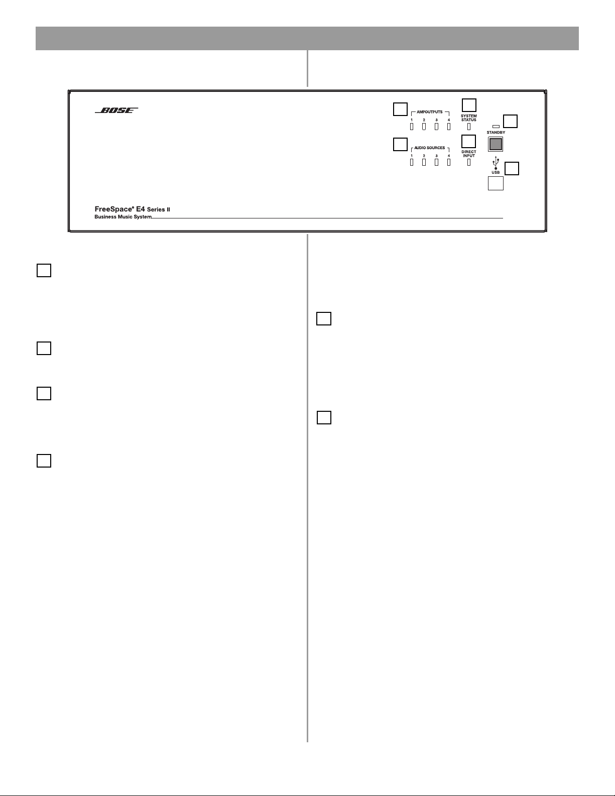
3.1 Front panel
3.0 E4 Hardware Description
3.1.1 Controls
1
STANDBY – The STANDBY button switches the unit
between standby and active. The color of the LED above the
switch indicates the status:
Amber = Unit is in standby
Unlit = Unit is active
2
USB – A USB communications port (for future use)
3.1.2 Indicators
3
SYSTEM STATUS – The SYSTEM STATUS LED indicates the
condition of the unit:
Green = Normal operation
Red = Fault condition
4
AMP OUTPUTS – These LEDs work in pairs (1 and 2, 3 and
4) and indicate the operating status of the four amplifier output
4
3
1
5
6
2
channels:
Green = Normal operation
Red = Fault condition
Unlit = No signal
5
AUDIO SOURCES – These LEDs indicate the operating
status of the four input sources:
Green = Good signal
Amber = Low signal
Red = Signal clipping
Unlit = No signal
6
DIRECT INPUT – The color of this LED indicates the condi-
tion of the source connected to the DIRECT IN/CONTROL connector on the rear panel.
Amber = Active bypass
Unlit = Normal operation
23 of 80
Page 5
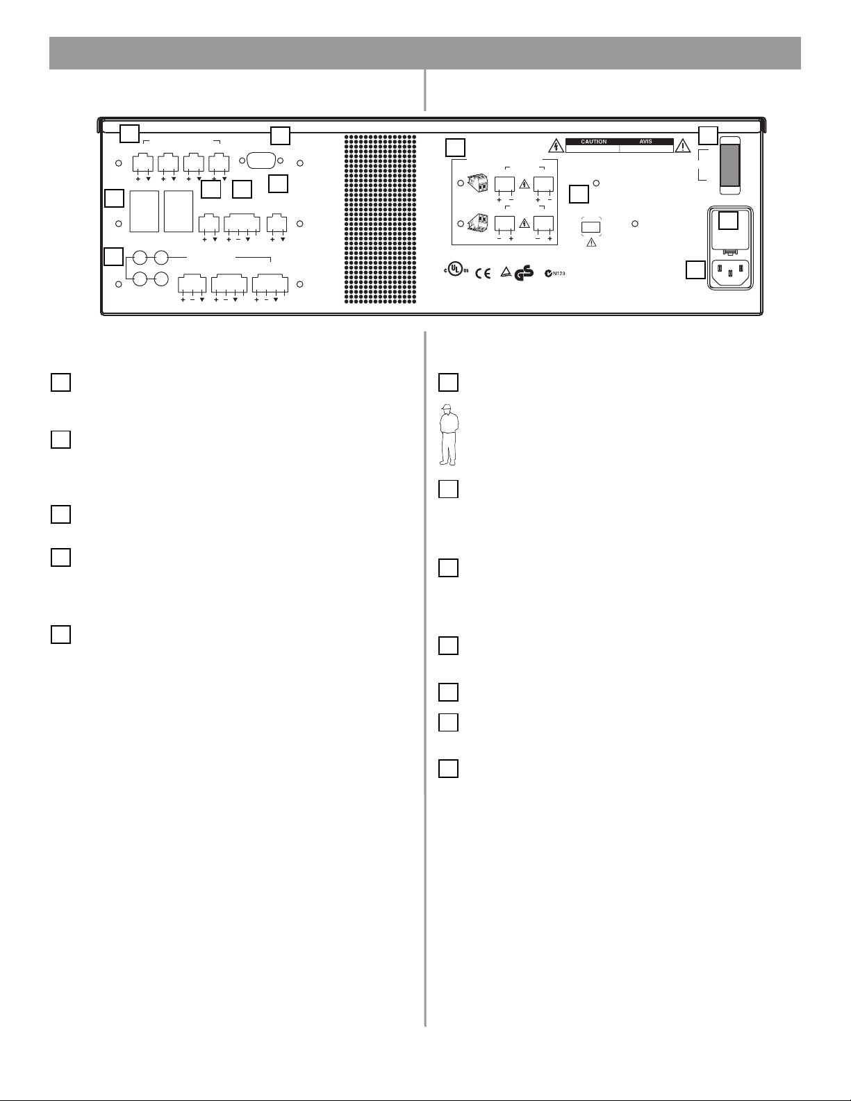
3.2 Rear panel
3.0 E4 Hardware Description
1
SENSE MICROPHONES
ZONE 1 ZONE 2 ZONE 3 ZONE 4
WAL L PLATE CONNECTIONS
1
3
LINE 1
2
4
LINE 2
3
5
REMOTE
ON/OFF
AUDIO SOURCES
AUX MIC/
LINE 3
4
PAGE/ MIC/
LINE OUT
LINE 4
RS232
7
MUSIC ON
ZONE 4
PBX OUT
12V
DIRECT IN/
CONTROL
PTT PTT
2
8
HOLD/
3.2.1 System controls
SENSE MICROPHONES – Input connectors for sensing
1
microphones used with the Auto Volume feature. See the Auto
Volume Kit.
2
RS-232 – Standard RS-232 communications port. Provides
a communications interface for a PC running FreeSpace
®
Installer™ software. The Installer™ software is used to configure
the E4 hardware.
WALL PLATE CONNECTIONS – Input connectors for Stan-
3
dard, Auto Volume, and Paging Zone user interfaces.
4
REMOTE ON/OFF – An input connector for a remote
STANDBY switch.
3.2.2 Audio source inputs
LINE 1/LINE 2 – Unbalanced audio inputs
5
AUX MIC/LINE 3 – Balanced audio input with phantom power
PAGE/MIC/LINE 4 – Balanced audio input with phantom power
DIRECT IN/CONTROL – Balanced (DSP bypass at max. power)
50/60H z
12
10
POWER
ON
OFF
11
6
USE ONLY CLASS 2 WIRING
CONNECTOR
ORIENTATION
®
LISTED 917D
AUDIO
EQUIPMENT
This device complies with part 15 of the FCC rules. Operation is
subject to the following conditions: (1)This device may not cause
harmful interference and (2)this device must accept any interference
received, including interference which may cause undesired operation.
Complies with Canadian ICES-003 Class A Spec.
ZONE OUT
12
ZONE OUT
34
geprüfte
TüV Rheinland
Sicherheit
WHILE POWER IS ON
RISK OF ELECTRICAL SHOCK
DO NOT OPEN
RISQUE DE CHOC ELECTRIQUE
NE PAS OUVRIR
9
OUTPUT
VOLTAGE
70V 100V
100/120V~AC T6.25A, L250V
DO NOT SWITCH
Bose Corporation, Framingham, MA 01701-9168
220/240V~AC T3.15A, L250V
300W MAX
FreeSpace E4 Series II
400 Watt System Electronics
Made in the U.S.A.
3.2.3 Amplifier outputs
6
ZONE OUT 1/2/3/4 – Speaker connections for four zones
Installer’s Note: Please notice the polarity markings when
wiring speaker cables to the ZONE OUT connectors.
CAUTION: DO NOT ground the minus (–) terminals.
7
ZONE 4 LINE OUT – A line-level output that duplicates the
program material from LINE 4. May be used to feed another
amplifier installed for a large zone. The 12V control output is used
®
to connect to Bose
8
MUSIC ON HOLD/PBX OUT – An audio output used to
amplifier sequence inputs.
provide music input to a PBX system
3.2.4 AC power
9
OUTPUT VOLTAGE – Sets the ZONE OUT lines to 70/100V.
Set fuse box to 100/120V for 70V; 220/240V for 100V
POWER ON/OFF – Switches AC power on or off
10
Fuse box – Configures the E4 for 100/120V or 220/240V. Set
11
OUTPUT VOLTAGE to 70V for 100/120V; 100V for 220/240V.
AC line cord jack – AC line voltage input
12
24 of 80
Page 6

4.0 Hardware Installation
4.1 Introduction
This section provides instructions for installing the FreeSpace®
E4 system hardware on a tabletop or in a rack.
4.2 Included accessories
The following accessories are shipped with the E4 unit in the
FreeSpace E4 System Accessory Kit (PC030105).
• 2-terminal input connectors (6) – For wiring
Auto Volume mics to the
SENSE MICROPHONES jacks
• 3-terminal input connectors (2) – For wiring
equipment to the AUX MIC/LINE 3 jacks
• 4-terminal input connectors (3) – For wiring
equipment to the ZONE 4 LINE OUT,
PAGE/MIC/LINE 4, and
DIRECT IN/CONTROL jacks
• 2-terminal output connectors (5) – For wiring speaker cables to the ZONE OUT jacks
• Rubber feet (4) – For installing the E4 unit on
a level surface
4.3 Placement guidelines
• Place the E4 unit where it is protected from heat and allowed
adequate ventilation.
• Place the E4 unit away from direct heat sources, such as heating vents and radiators.
• Make sure that air can circulate freely behind, beside, and
above the unit. Allow six inches on all sides.
Installer’s Note: Do not allow the chassis to exceed the
maximum operating temperature of 50° C (122° F). Be aware
of conditions in an enclosed rack that may increase the temperature above room-ambient conditions.
4.4 Shelf mounting the E4 unit
The E4 unit is ideal for shelf mounting. The included accessory kit
contains four rubber feet for the bottom of the E4 chassis. The
rubber feet will protect the surface on which the E4 unit is
installed and help prevent movement of the E4 unit. Be sure to
follow the “Placement Guidelines” previously described when
choosing a location for the E4 unit.
• Replacement voltage label (2) – Used on
the OUTPUT VOLTAGE selection switch
• FreeSpace Installer™ software CD –
Contains application software for programming the E4 system
25 of 80
Page 7

4.0 Hardware Installation
4.5 Rack mounting the E4 unit
Required accessory: FreeSpace® E4 System Rack Mount Kit
(PC029858)
S
T
U
M
E
TP
T
U
O
YS
P
S
M
A
S
U
TAT
S
23
14
ES
C
R
T
U
C
E
SO
IR
IO
D
D
U
A
UT
P
IN
23
14
Y
B
D
N
A
T
S
SB
U
Rack ears
(8) #8-32 x 1/2 in
The E4 unit requires three 1.75" (4.4 cm) rack space units with a
16" (40.6 cm) inside depth (including the rear supports). When
mounting, use four screws with washers to prevent marring the
front panel. Neoprene rubber washers are a good choice
because they grip the screw head and prevent the screws from
backing out from vibration or during transportation.
Installer’s Note: If the E4 unit is to be transported while
mounted in a rack, be advised that the rear of the E4 unit
must be mechanically supported. Install a shelf under the unit
or use brackets in such a way as to support the rear of the
unit. Failure to use proper mounting hardware may result in
damage to the E4 unit during transport.
FreeSpace
m
te
s
Sy
c
i
us
M
ss
e
in
s
u
B
Attaching rack ears to the E4 chassis
FreeSpace
em
t
s
y
S
ic
us
M
s
s
e
in
s
u
B
Attaching the E4 chassis to the rack
(mounting screws not provided)
S
T
U
P
T
U
O
Y
P
S
M
A
TATUS
S
3
2
14
S
E
C
R
U
O
S
IR
IO
D
D
AU
IN
23
14
M
E
T
S
BY
D
N
TA
S
T
C
E
T
U
P
B
S
U
26 of 80
Page 8

4.0 Hardware Installation
O
T
F
U
4.6 Installing accessories
4.6.1 Sensing microphones
Required accessory:
FreeSpace® E4 System Auto Volume Mic Kit [PC029859 (U.S.),
PC029860 (Euro)]
Wall plate-microphone
assembly
Microphone installation:
The wall plate-microphone assembly can be installed using a
junction box, or the microphone can be removed from the wall
plate and mounted directly on a flat surface.
Junction box installation Surface mounted mic
Paint plug
(2) Wire nuts
(2) #6-32 (3 mm) screws
4.6.2 User interfaces
Required accessory: FreeSpace E4 System User Interface Kit
[PC029856 (U.S.), PC029857 (Euro)] or
FreeSpace E4 Auto Volume Interface Kit
[PC030101 (U.S.), PC030102 (Euro)] or
FreeSpace E4 System Page Interface Kit
[PC030103 (U.S.), PC030104 (Euro)]
B
Keypad
A
Wall plate
D
(2) #6 x 32 / (2) M4 x 20 mm
Required additional equipment (not supplied):
Single-gang
E
RJ45
connector
F
Cat 5 cable
(with 4 twisted pairs)
electrical box
C
Back plate
G
Recommended wire length:
Up to 2000 feet (610 m) max., 24 AWG (0.2 mm2) shielded twisted
pair (shield tied to minus at E4, floated at sense mic).
Painting:
Before painting the wall
plate, install the supplied temporary plug
over the microphone
opening. Remove the
plug when finished.
Mounting locations:
For mounting instructions, see “Mounting guidelines for sensing
microphones” on page 15.
Assembly:
A
D
G
SEN
Z
O
N
SE
E
1
M
IC
R
Z
O
O
P
N
H
E
ON
2
E
S
Z
O
C
B
NE
3
WA
Z
LL
PLA
1
TE
CON
NEC
T
IO
2
N
S
3
RE
MO
O
N
4
/O
LIN
E
1
L
IN
E
2
A
UD
AUX
IO
S
O
M
IC/
LIN
E
3
F
27 of 80
Page 9

4.0 Hardware Installation
Keypad schematic:
LED
LED
S1
S2
+5VD
.33µF
D1
R1
562
Source 1
+5VD
D2
R2
562
Source 2
+5VD
C7
+5VD
1 2 3 4 5 6 7 8
LED
LED
+5VD
S6
+5VD
S5
+5VD
D6
R6
562
Volume Up
D5
R5
562
Volume Down
User interface wiring:
Installer’s Note: Use only standard ethernet (Cat 5) cable to
connect the user interface to the E4 unit. DO NOT use crossover (XOV) cables.
WALL PLATE
CONNECTOR BLOCK
POS 1
POS 2
POS 3
POS 4
POS 5
POS 6
POS 7
POS 8
E4 RJ45
PIN 1-8
PIN 1
PIN 2
PIN 3
PIN 4
PIN 5
PIN 6
PIN 7
PIN 8
S3
D3
R3
562
Source 3
LED
Recommended cable lengths:
One wall plate
using CAT 5
E4
Two wall plates
using CAT 5
E4
2000 ft (610 m) max.
1300 ft (396 m) max.
LED
S4
D4
R4
562
Mute
or
Auto Volume
On/off
For operating information, see “User Interface Operation” on
page 59.
28 of 80
Page 10

4.0 Hardware Installation
N/
C
O
P
4.7 System wiring
Installer’s Note: Disconnect the E4 unit from the AC
(mains) power before making any input/output connections.
4.7.1 Auto volume microphone inputs
Connect each sensing microphone to the SENSE MICROPHONES jacks on the E4 rear panel.
SENSE MICROPHONES
ZONE 1 ZONE 2 ZONE 3 ZONE 4
WALL PLATE CONNECTIONS
132
LINE 1
LINE 2
REMOTE
ON/OFF
4
AUDIO SOURCES
AUX MIC/
LINE 3
4.7.2 Serial data communications
Connect your PC to the E4 unit using a straight-wired serial data
cable (DB9 male to DB9 female).
LINE OUT
PAGE/ MIC/
LINE4
ZONE4
RS232
MUSI
PBX
12V
DIRECT I
CONTROL
PTT
4.7.3 User interface connections
Connect the user interface from each zone to the appropriate
WALL PLATE CONNECTION jack.
Installer’s Note: Only use standard ethernet (Cat 5) cable
to connect the user interface to the E4 unit. DO NOT use
crossover (XOV) cables.
SENSE MICROPHONES
ZONE 1 ZONE 2 ZONE 3 ZONE 4
WALL PLATE CONNECTIONS
1
2
REMOTE
ON/OFF
3
4
HOL
LINE 1
LINE 2
AUDIO SOURCES
AUX MIC/
LINE 3
PAGE/ MIC/
LINE4
4.7.4 Remote standby switch
If you are installing a remote standby switch, connect it to the
REMOTE ON/OFF input.
Remote Standby
Switch
REMOTE ON/OFF
RS232
ZONE4
LINE OUT
12V
DIRECT IN/
CONTROL
PTT PTT
E4
MUSIC ON
HOLD/
PBX OUT
RS232 port pinout
Normally Open
Switch (latching)
29 of 80
Page 11

4.0 Hardware Installation
4.7.5 LINE 1/LINE 2 source input
Audio sources can be connected to the LINE 1 and LINE 2 inputs
using one of the following cable types.
Source Connector
S
T
RCA
XLR
Phone
Plug
(Balanced)
Phone
Plug
(Unbalanced)
12
3
T R S
TS
S
T
1
3
2
E-4 LINE 1/LINE 2
S
S
R
T
S
S
T
S
S
T
T
T
T
4.7.6 AUX MIC/LINE 3 source input
A microphone or an audio source can be connected to the MIC/
LINE 3 input using one of the following cable types.
Source Connector
RCA
XLR
Phone
Plug
(Balanced)
Phone
Plug
(Unbalanced)
S
T
12
3
T R S
TS
S
T
1
3
2
E-4 AUX MIC/LINE 3
S
R
T
S
T
30 of 80
Page 12

4.0 Hardware Installation
4.7.7 PAGE/MIC/LINE 4 source input
A microphone or an audio source can be connected to the PAGE/
MIC/LINE 4 input using one of the following cable types.
Source Connector
RCA
XLR
Phone
Plug
(Balanced)
Phone
Plug
(Unbalanced)
Normally
Open Switch
(latching)
S
T
1
3
T R S
TS
2
S
T
1
3
2
E-4 PAGE/MIC/LINE 4
PTT
PTT
S
R
T
PTT
S
T
PTT
4.7.8 DIRECT IN/CONTROL source input
A microphone or an audio source can be connected to the
DIRECT IN input using one of the following cable types. The control (PTT) input requires a normally open switch.
Source Connector
RCA
XLR
Phone
Plug
(Balanced)
Phone
Plug
(Unbalanced)
Normally
Open Switch
(latching)
S
T
1
3
T R S
TS
2
S
T
1
3
2
E-4 DIRECT IN/CONTROL
PTT
PTT
S
R
T
PTT
S
T
PTT
PTT
PTT
31 of 80
Page 13

4.0 Hardware Installation
on
E-
m
Ele
4.7.9 Amplifier ZONE OUT outputs
Speaker systems in up to four zones can be connected to the
ZONE OUT amplifier outputs.
Installer’s Note: Please notice the polarity markings on
the ZONE OUT 1-4 connectors. Wire each connection as
shown, using the 2-terminal output connector from the
accessory kit.
Installer’s Note: DO NOT
ground the minus (–) side of
the line.
USE ONLY CLASS 2 WIRING
CONNECTOR
ORIENTATION
ZONE OUT
12
ZONE OUT
34
1. Install a two-terminal
output connector
(supplied) on the
speaker cable from
each zone.
+
–
2. Plug the speaker cable connectors into the appropriate
ZONE OUT jack.
Installer’s Note: Be sure to position the cable connector in
the correct orientation for the ZONE OUT jacks: Screw heads
face upward for ZONE OUT 1 and 2 jacks, screw heads face
downward for ZONE OUT 3 and 4 jacks.
4.7.10 Output voltage setting (70/100V)
Check the OUTPUT VOLTAGE switch setting and change if
needed.
OUTPUT
VOLTAGE
70V 100V
DO NOT SWITCH
WHILE POWER IS ON
Installer’s Note: Disconnect power from the E4 unit before
changing the OUTPUT VOLTAGE setting.
To change the setting to 70V or 100V, remove the label,
change the switch setting and replace the label. Additional
labels are supplied in the accessory kit.
Installer’s Note: Changing this setting requires a corresponding change to the fuse box configuration: 70V is
selected for 100-120VAC; 100V is selected for 220-240VAC.
T
his
su
harm
re
ce
C
o
CONNECT
ORIENT
®
LI
ST
E
D
9
1
AUDI
7D
EQ
O
U
IP
M
E
N
d
e
b
v
je
c
t
fu
l in
iv
e
d
m
plie
T
ice
to
th
te
,in
clu
s
w
USE ONL
ATIO
co
m
p
e
fo
rfe
llo
re
n
din
it
g
h
C
a
n
OR
N
li
e
s
w
ith
w
in
c
g
e
an
c
int
d
(2
e
rfe
ad
re
ia
n
IC
Y
CLASS 2
W
IRIN
G
ZONE OUT
12
ZONE OUT
34
T
ü
V Rheinla
nd
pa
rt
o
15
n
d
gepr
itio
o
)this
f
Sicherheit
ü
th
n
fte
s:
nce
dev
e
F
(1)T
C
w
ice
E
C ru
h
h
S
ic
is
-0
m
h m
0
le
d
u
3
e
st
s
v
.
C
a
ic
y
ac
la
O
e
c
s
ce
p
a
s A
m
u
e
p
s
ra
ay
t a
e
Sp
tio
u
n
n
e
nd
y
ot
c
in
.
esir
t
e
ed
rfe
op
e
ra
R
IS
K
O
F
E
L
E
C
T
R
D
I
C
O
A
N
L
O
S
T
H
O
O
C
P
E
K
N
R
I
S
Q
U
E
D
E
C
HO
N
C
E
E
P
LEC
A
S
O
TR
U
I
V
Q
R
U
I
R
E
OUTPU
VO
LTAGE
T
7
0V
10
0V
DO NOT SWITCH
WHILE PO
WER IS ON
Bose Corporati
400
FreeSpace
W
att Syste
100/120V~AC T6.25
220/240V~AC T3.15
M
odel
n is
c
au
se
re
n
c
e
ti
on
.
300W
50/60H
ON
POWER
OFF
A, L250V
A, L250V
z
M
AX
32 of 80
Page 14

4.0 Hardware Installation
4.7.11 ZONE 4 LINE OUT output
The ZONE 4 LINE OUT jack provides a line-level output that
duplicates the program material on LINE 4. This may be used to
feed another Bose
control output is used to connect to Bose amplifier sequence
inputs.
Source Connector
S
T
RCA
XLR
Phone
Plug
(Balanced)
Phone
Plug
(Unbalanced)
Control Signal
1
3
T R S
TS
®
amplifier installed for a large zone. The 12V
E-4 ZONE 4 LINE OUT
S
T
1
3
2
2
S
R
T
S
T
12V
12V
12V
12V
4.8 AC power connections
Installer’s Note: The fuse box configuration must be coordinated with the 70/100V OUTPUT VOLTAGE setting: 70V
should be selected for 100-120VAC; 100V should be selected
for 220-240VAC.
Fuse box configuration
The fuse box is configured at the factory according to the specifications of your order. Should you need to replace the fuse, follow
these steps:
1. Using a thin screwdriver blade, open the fuse box. Pull out
the drawer and remove the fuse.
Voltage
selection
indicator
2. Insert a new fuse of the same type and rating into the fuse
box drawer.
Fuse
3. Slide the fuse box drawer back into the fuse box.
Bose 1600, 1800 or M2150 Amplifier
12V
AC power cord receptacle
Insert the proper power cord for the voltage used in your region.
Power cord
receptacle
33 of 80
Page 15

Bose® Product Sales Conditions
Limited Warranty Policy
and
Conditions of Sale
Bose Corporation
The Mountain
Framingham, MA 01701
What is covered:
All parts defective in material and workmanship. This limited
warranty for the Bose Freespace
the functionality of the system for its normal, intended use as
specified in the Owner’s Guide and does not cover a malfunction
that has resulted from improper or unreasonable use or maintenance, accident, excess moisture, improper packing,
lightning, power surges, or unauthorized tampering, alteration or
modification while not under the control of Bose. Bose systems
are not designed to be used in every environment, so please
review your Owner’s Guide.
WHERE PERMITTED, THE PROVISIONS OF THIS LIMITED
WARRANTY ARE IN LIEU OF ANY OTHER WRITTEN
WARRANTY, WHETHER EXPRESS OR IMPLIED, WRITTEN OR
ORAL, INCLUDING ANY WARRANTY OF MERCHANTABILITY
OR FITNESS FOR A PARTICULAR PURPOSE.
For how long:
In countries where the duration of the warranty is not determined
by statute, the Bose Limited Warranty lasts five years from the
purchase date. For countries where minimum warranty terms are
determined by statute, the warranty term is the longer of the
statutory period or the term listed above.
What we will do:
We will repair or replace any defective parts within a reasonable
period of time and free of charge.
How you can obtain warranty service:
1. You can ship the system to either a Bose Service Agency or to
Bose directly with a proof of purchase from an authorized dealer.
Please:
A. Properly and carefully pack the product for shipping. If you
need a carton for shipping, contact Bose for a new carton.
B. Label and ship the product to the appropriate Bose
location.
C. Please contact Bose to get a return reference number.
Place this number prominently on the outside of the carton.
2. You can return the system with proof of purchase from an
authorized dealer to a Bose Service Agency or directly to
Bose. Proof of purchase is not required where it is excluded
by statute.
®
E4 system (“system”) covers
Other Rights:
EXCLUSIVE REMEDY:
THIS LIMITED WARRANTY IS FULLY TRANSFERABLE
PROVIDED THAT THE CURRENT OWNER FURNISHES THE
ORIGINAL PROOF OF PURCHASE FROM AN AUTHORIZED
BOSE DEALER. THE MAXIMUM LIABILITY OF BOSE SHALL
NOT EXCEED THE ACTUAL PURCHASE PRICE PAID BY YOU
FOR THE PRODUCT. IN NO EVENT SHALL BOSE BE LIABLE
FOR SPECIAL, INCIDENTAL, CONSEQUENTIAL OR INDIRECT
DAMAGES. SOME PLACES DO NOT ALLOW LIMITATIONS ON
THE EXCLUSION OR LIMITATION OF RELIEF, SPECIAL,
INCIDENTAL, CONSEQUENTIAL OR INDIRECT DAMAGES OF
THE LIMITATION OF LIABILITY TO SPECIFIED AMOUNTS, SO
THE ABOVE LIMITATIONS OR EXCLUSIONS MAY NOT APPLY
TO YOU.
OTHER CONDITIONS:
FOR YOUR BENEFIT, WE RECOMMEND THAT YOU RECORD
YOUR SERIAL NUMBERS(S), FOUND ON THE PRODUCT(S),
AND OTHER PURCHASE INFORMATION, AND KEEP IT WITH
YOUR PERSONAL RECORDS ALONG WITH PROOF OF
PURCHASE. IF NECESSARY, THIS INFORMATION WILL
ALLOW US TO BETTER SERVE YOUR NEEDS.
THIS LIMITED WARRANTY GIVES YOU SPECIFIC RIGHTS
SUBJECT TO SPECIFIED CONDITIONS. YOU MAY ALSO HAVE
OTHER LEGAL RIGHTS WHICH APPLY TO THE PRODUCT
YOU HAVE ACQUIRED. THESE LEGAL RIGHTS VARY FROM
STATE TO STATE OR COUNTRY TO COUNTRY. SOME PLACES
DO NOT ALLOW THE EXCLUSION, RESTRICTION OR MODIFICATION OF CERTAIN IMPLIED RIGHTS OR THEIR EFFECT. IN
THOSE SITUATIONS THIS LIMITED WARRANTY WILL ONLY
APPLY TO THE EXTENT THAT THE APPLICABLE LAW ALLOWS.
OTHER LAWS PROVIDE YOU WITH A STATUTORY CLAIM
AGAINST THE SELLER.
The laws of your state or country may provide you with legal
claims against the seller or manufacturer of this product. The
Limited Warranty does not affect those rights.
Remedies:
The provisions of this limited warranty are in lieu of any other
warranties or conditions, except those provided by law. This
Limited Warranty does not affect any legal rights provided to you
by law and does not preclude any legal remedy you may have
under the law.
This Limited Warranty is fully transferable provided that the
current owner furnishes the original proof of purchase from an
authorized Bose dealer.
This Limited Warranty is void if the label bearing the serial
number has been removed or defaced.
77 of 78
Page 16

78
©2004 Bose Corporation, The Mountain,
Framingham, MA 01701-9168 USA
279145 AM Rev.00 CCM-000922
 Loading...