

Page 1

Contents
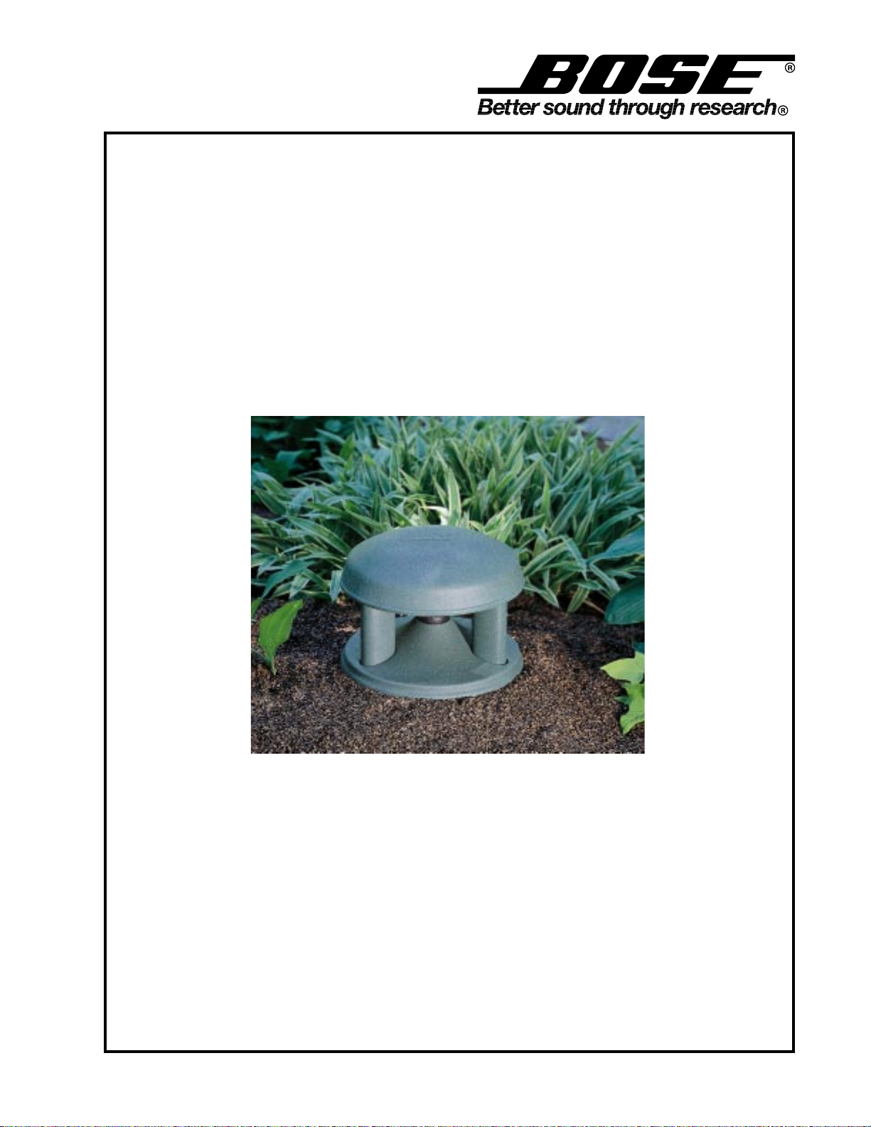
Click here for FS360 Image
ECN 29027 added "end user owners guide"
Product Description ..........................................................................................................................2
Specifications ....................................................................................................................................2
Disassembly/Assembly Procedures................................................................................................3
Figure 1. Wiring Diagram.....................................................................................................................3
Test Procedures ................................................................................................................................4
Figure 2. 4 Ohm Passive Version Equalizer Schematic Diagram ........................................................4
Figure 3. 70/100V Passive Version Equalizer Schematic Diagram......................................................4
Main Part List..................................................................................................................................... 5
Figure 4. Exploded View ......................................................................................................................6
Equalizer PCB Part List ....................................................................................................................7
Packaging Part List ...........................................................................................................................7
Figure 5. Packaging View ....................................................................................................................7
Figure 7. Equalizer PCB Component Layout .......................................................................................7
Figure 6. Position of EQ PCB on Driver...............................................................................................7
PROPRIETARY INFORMATION
THIS DOCUMENT CONTAINS PROPRIETARY INFORMATION
OF BOSE
ONLY FOR THE PURPOSE OF SERVICING THE IDENTIFIED
BOSE PRODUCT BY AN AUTHORIZED BOSE SERVICE CENTER OR OWNER OF THE BOSE PRODUCT, AND SHALL NOT
BE REPRODUCED OR USED FOR ANY OTHER PURPOSE.
CAUTION: The FreeSpace
user serviceable parts. To prevent warranty infractions, refer
servicing to warranty service centers or factory service.
CORPORATION WHICH IS BEING FURNISHED
®
360P/360 loudspeaker contains no
The FreeSpace 360P/360 loudspeaker is covered by a 5 year warranty
WARRANTY INFORMATION
1
Page 2

PRODUCT DESCRIPTION
The FreeSpace® 360P/360 is a full-range environmental loudspeaker intended for background
music and paging. There are three versions. The FS360P 70V/100V, 25W version has an internal
passive equalizer. The FS360P 4 Ohm, 25W version has an internal passive equalizer. The FS360
70V/100V, 25W version requires a Bose
the amplifier.
The FreeSpace 360P/360 can be installed in-ground with approximately one-half of the speaker
exposed above ground. It can also be permanently secured above ground on a horizontal surface
such as a deck.
®
FS360 active equalizer to be connected to or located in
SPECIFICATIONS
External dimensions:
Weight (packed system):
Internal cabinet volume:
Port:
Impedance (nominal):
Power Handling:
Sensitivity (1W, 1M):
13.80" base diameter x 14.6" height
(320 mm base diameter x 370 mm height)
12.0 lbs. (5.4 kg)
Top enclosure: 142 cubic inches (2.3 liters)
Bottom enclosure: 659 cubic inches (10.8 liters)
Diffuser port: Tuned to 80 Hz
Three connecting ports: Tuned to 180 Hz
Non-passive version: 214 Ohm, 70V transformer @ 25W
271 Ohm, 100V transformer @ 25W
Passive version: 414 Ohm, 70V transformer @ 25W
852 Ohm, 100V transformer @ 25W
Non-transformer version: 4 Ohms
25W (70V, 100V) continuous per IEC-268-5, 100 hour duration
80 dB SPL, free field, per IEC-268-5 (for octave-band centered at 400 Hz)
2
Page 3

DISASSEMBLY/ASSEMBLY PROCEDURES
Transformer
Red
Black
Wire harness
Red
Black
+
_
Wire post
(two places)
COM
+IN
(Refer to Figure 4)
1. Mounting Plate Removal
1.1 Remove the four screws (20) that secure
the mounting plate (10) to the base housing
(14).
1.2 Lift off the mounting plate.
2. Mounting Plate Replacement
2.1 Align the mounting plate (10) to the base
(14). Replace the four screws (20) that secure
the mounting plate to the base.
3. Driver/Equalizer PCB Removal
Note: For versions without a passive equal-
izer, ignore references to the equalizer PCB.
3.1 Remove the three screws (6) that secure
the driver protector (4) and the driver (1) to the
cap housing (13).
3.2 Lift off the driver protector. The equalizer
PCB is attached by a screw to the driver
magnet. Work the driver with attached equalizer PCB out of the cap housing.
3.3 Cut the wires as close as possible from the
driver terminal. Remove the screw that secures the equalizer PCB to the driver magnet.
4. Driver/Equalizer PCB Replacement
Note: For versions without a passive equal-
izer, ignore references to the equalizer PCB.
4.1 Referring to Figure 6, position the equalizer PCB on the driver and using the screw
removed in procedure 3.3, attach the equalizer
PCB to the driver (1) magnet. Attach the red
wire to the positive (+) driver terminal and the
black wire to the negative (-) driver terminal.
Refer to Figure 1 Wiring Diagram.
5. Transformer Removal
Note: For transformer versions only.
5.1 To gain slack in the wires, perform proce-
dure 3.1 and 3.2 first.
5.2 Remove the four screws (8) that secure
the transformer plate (11) to the cap housing
(13). Lift up the transformer plate.
5.3 Make a note of the wiring configuration
and then remove the wires from the transformer (3).
5.4 Remove the two nuts (9) that secure the
transformer to the transformer plate.
6. Transformer Replacement
Note: For transformer versions only.
6.1 Align the transformer (3) to the transformer
plate (11) and replace the two nuts (9) that
secure the transformer to the transformer
plate.
6.2 Referring to the wiring configuration notes
taken in procedure 5.3 or to Figure 1 Wiring
Diagram, attach the wires to the transformer.
6.3 Lower the transformer with attached
transformer plate into the cap housing (13)
and secure into place with four screws (8).
6.4 Use procedure 4.2 and 4.3 to replace the
driver.
EQ PCB
E4
Red
E2
Cap
(in harness)
Wire harness
Red
Black
Transformer
+IN
COM
Wire post
(two places)
Red
Black
Passive Version
+
_
4.2 Work the assembled driver and equalizer
into the cap housing (13). Twist together any
excess wire to prevent a wire buzz.
4.3 Align the driver protector (4), the driver
and the driver gasket (2) to the cap housing.
Replace the three screws (6) that secure the
driver to the cap housing.
Non-passive Version
Figure 1. Wiring Diagram
3
Page 4

TEST PROCEDURES
1. Phase Check
1.1 Referring to Figure 1, ensure proper wiring
of the loudspeaker.
2. Rub and Tick Test
2.1 Apply a 35Vrms, 80Hz signal to the input
of the loudspeaker.
Note: No extraneous noises such as rubbing,
scraping or ticking should be heard. To distinguish between normal suspension noise, rubs
and ticks, displace the cone of the driver with
your finger. If the sound can be made to go
away or get worse, it’s a rub or tick and the
driver should be replaced. If the noise stays
the same, it’s normal suspension noise and
will not be heard with regular program material.
3. Air Leak Test
3.1 Apply a (6Vrms for 4 Ohm version)
(35Vrms for transformer version), 80Hz signal
to the input of the loudspeaker.
3.2 Check for air leaks around the cabinet,
driver, and transformer plate. Replace any
gasket that is found to be defective.
4. Sweep Test
4.1 Apply a (6Vrms for 4 Ohm version)
(35Vrms for transformer version), 50Hz signal
to the input of the loudspeaker.
4.2 Sweep the signal generator from 50Hz to
5kHz. Listen for buzzes, rattles or extraneous
noises from the driver or internal parts. A
whooshing noise from the port around 80Hz is
acceptable. Replace any driver that buzzes.
Redress any wire that buzzes.
NOT USED
JP1
10uF, BP, 50V
6.2 Ohm
1.5mH
PTC1
C1
47uF, BP, 50V
C2
R1
L1
E4
IN-
E3
R2
2.4 Ohm
Figure 2. 4 Ohm Passive Version Equalizer Schematic Diagram
NOT USED
JP1
E4
NO CONNECTION
IN-
E3
R2
2.4 Ohm
10uF, BP, 50V
6.2 Ohm
1.5mH
NOT USED
PTC1
C1
NOT USED
C2
R1
L1
E2
OUT+IN+
OUT-
E1
E2
OUT+IN+
OUT-
E1
Figure 3. 70/100V Passive Version Equalizer Schematic Diagram
4
Page 5

MAIN PART LIST
(Item numbers are referenced in Figure 4)
Item Number Description Part
Number
4.5" Driver (active equalization version) 196241 1
4.5 " Driver With Equalizer PCB (transformer passive version)
Consists of:
Driver, 4.5”, Environmental
Equalizer PCB
Screw, Tapp, 8-32x.375, HEXW, HEX
1
2 Gasket, Driver, 4.5” 116572 1
3
4Protector, Driver1200031
5
6
7
8 Screw, TAPP, 8-32x.375, PAN, XRC/S 145727-06 4
9 Nut, Hex, 8-32, KEPS 100413-2 2
10 Plate, Mounting 193903 1
11 Plate, Transformer, Black 191927-001 1
12 Grille, Diffuser, Black 191926-001 1
13
14
Note: The active equalization version requires the use of an external Bose
The passive version has a passive equalizer PCB mounted to the rear of the driver.
Washer, Fender, Non-Magnetic
4.5 " Driver With Equalizer PCB (4 Ohm passive version)
Consists of:
Driver, 4.5”, Environmental
Equalizer PCB
Screw, Tapp, 8-32x.375, HEXW, HEX
Washer, Fender, Non-Magnetic
Transformer, 70V, 25W 196236
Transformer, 100V, 25W 196237
70V Wire Harness, With Inline 6.8 uF Cap. (passive version)
(25 uF, 150V, 20%, BP Capacitor)
100V Wire Harness, With Inline 4.7 uF Cap. (passive version)
(4.7 uF, 100V, 5%, NP Capacitor)
Wire Harness (active equalization and 4 Ohm passive version) 191929
Screw, TT, 8-32x.75, HEX, SL/XREC (passive version) 256070-08
Screw, TAPP, 8-32, PAN Head (active equalization version) 145727-06
Screw, TAPP, 8-10, .75, HEXW, HEX (passive version) 178835-12
Screw, TAPP, 8-11, PAN, XREC (active equalization version) 193902-12
Housing, Cap, Granite Green (passive version) 190691-005
Housing, Cap, Green (active equalization version) 190691-003
Housing, Base, Granite Green (passive version) 190690-005
Housing, Base, Green (active equalization version) 190690-003
®
active equalizer.
254390
254379
254378
134517-06
181700-01
257251
254379
257250
134517-06
181700-01
254428
125959
252370-001
252369-475
Qty.
1
1
1
1
1
1
1
1
1
1
1
1
3
3
1
1
5
Page 6
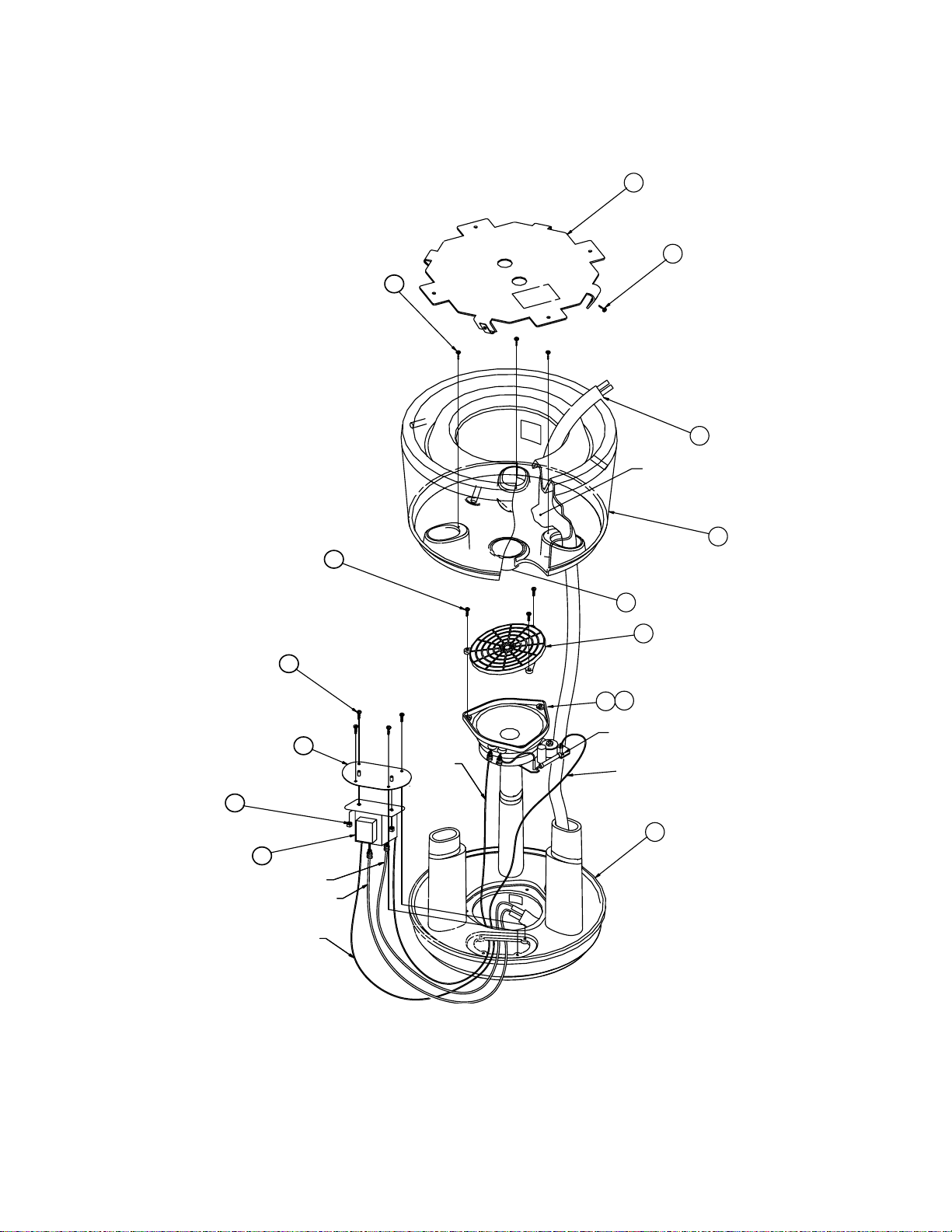
10
20
4x
3x
7
5
CAPACITOR (IN HARNESS)
14
3x
6
12
2x
9
3
No transformer in
the 4 Ohm version
4x
8
11
BLACK
RED
RED
BLACK
Figure 4. Exploded View
2
1
EQ PCB
RED
4
13
6
Page 7
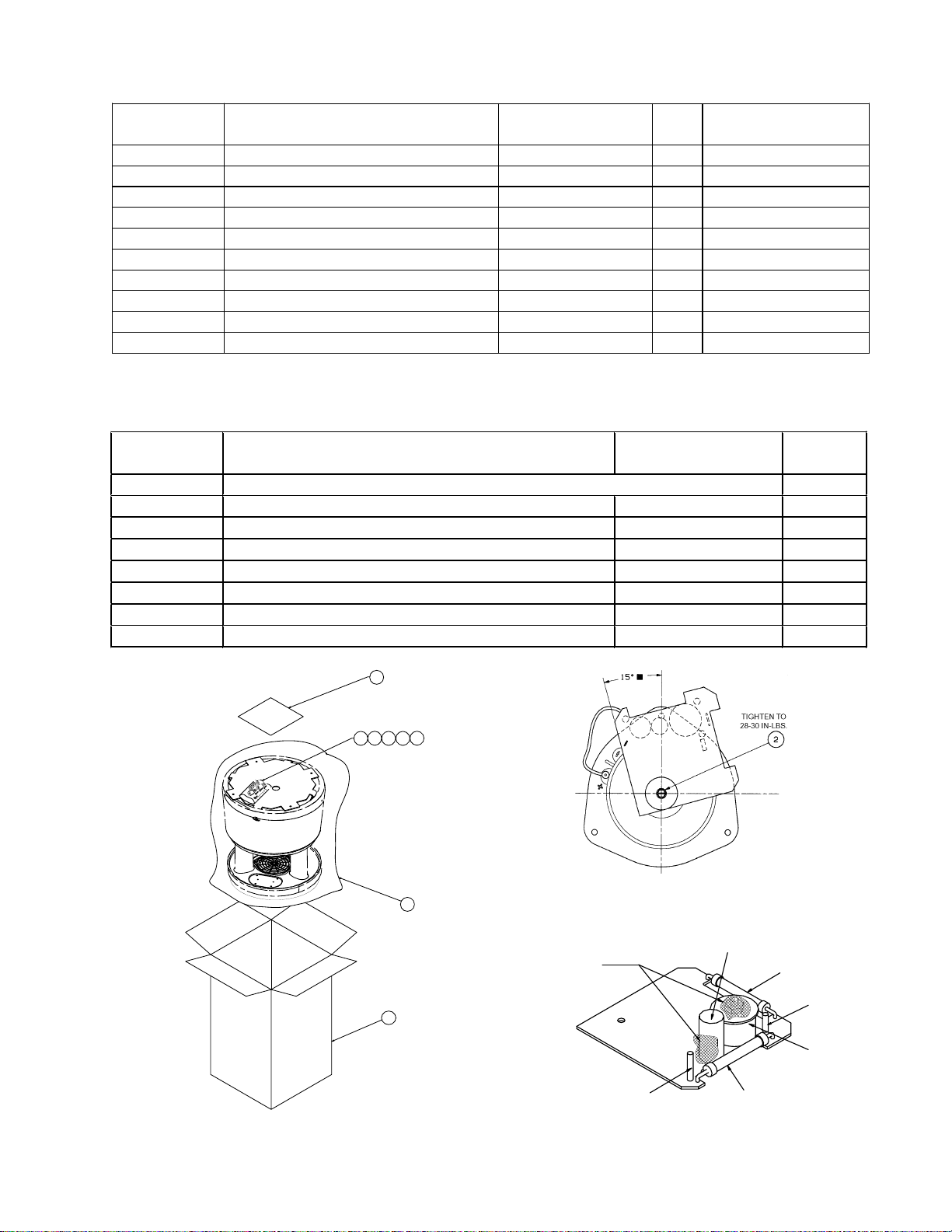
EQUALIZER PCB PART LIST
(Passive version)
Reference
Description Part Number Qty. Note
Designator
R1 6.2 Ohm, WW, 5W, 10% 125605-6R2 1
R2 2.4 Ohm, WW, 5W, 10% 125605-2R4 1
C1 47uF, EL, BP, 85, 50V, 20% 136548 1 4 Ohm version only
C2 10 uF, EL, BP, 85C, 50V, 20% 138365 1
L1 1.5 mH 139571 1
PTC1 Polyswitch, 60V, RXE135 190348-135 1 4 Ohm version only
- Screw, Mach, 6-32, PAN, XREC 181701-01 1
- Nut, HEX, 6-32 103234-632 1
- Washer, Fender, Non-Magnetic 181700-01 1
- Pin, Grooved, .52x.34x.045 129000-5234 2
PACKAGING PART LIST
Item
Number
15Manual, Owner’s 254405 (PRO installer) 259124 (end user) 1 each
16 Carton 254393 1
17 Bag, Poly, 48X24X14X2 Mil 128238 1
18 Connector, Wire Nut, 16-22 AWG 188199-001 2
19 Bag, Poly, 3x3x2 Mil 107305 1
20 Screw, Tapp, 8-11, PAN, XREC, 1.75 193902-28 4
21 Washer, Flat, .438” Diameter, #8 137923-08 4
22 Connector, Butt Splice, 10-22 AWG 198380-2218 1
Description Part Number Qty.
15
20
22
21
18
19
17
16
Figure 6. Position of EQ PCB on Driver
HOT MELT SHOULD NOT COVER
RESISTORS OR WIRE WRAP PINS.
E2
+ OUTPUT
C2
R2
+ INPUT
L1
R1
E4
Figure 5. Packaging View
Figure 7. Equalizer PCB Component Layout
7
Page 8
FreeSpace® 360 Loudspeaker
Click here to go to table of contents
Passive (FS360P)
Non-passive (FS360)
©
2000 Bose Corporation
Service Manual
Part Number 197458 REV. 01
Page 9

Specifications and Features Subject to Change Without Notice
Bose Corporation
The Mountain
Framingham Massachusetts USA 01701
P/N 197458 REV. 01 6/2000 For Technical Assistance or Part Orders, Call 1-800-233-4408
 Loading...