

Page 1
FreeSpace® 3
Loudspeaker System
©2006 Bose Corporation
Service Manual
Part Number 256589-SM Rev. 01
Page 2

CONTENTS
Contents ............................................................................................................................................2
Warranty Information........................................................................................................................2
Specifications ....................................................................................................................................3
Disassembly/Assembly Procedures ........................................................................................... 4-6
Figure 1. FreeSpace® 3 Disassembly View ..................................................................................... 6
Test Setup Procedures ................................................................................................................. 7-8
Figure 2. Test Setup Diagrams .......................................................................................................... 7
Main Part List.....................................................................................................................................9
Figure 3. FreeSpace 3 Bass Module Exploded View ........................................................................9
Crossover Electrical Part List ........................................................................................................ 10
Crossover Mechanical Part List..................................................................................................... 11
Figure 4. Crossover Assembly View ...............................................................................................11
Packaging Part List, Refer to Figure 5 ..........................................................................................12
Figure 5. Packaging Exploded View ................................................................................................ 12
Figure 6. Crossover Assembly Schematic Diagram ....................................................................... 13
Service Manual Revision History ................................................................................................... 14
PROPRIETARY INFORMATION
THIS DOCUMENT CONTAINS PROPRIETARY INFORMATION OF
BOSE CORPORATION WHICH IS BEING FURNISHED ONLY FOR
THE PURPOSE OF SERVICING THE IDENTIFIED BOSE PRODUCT
BY AN AUTHORIZED BOSE SERVICE CENTER OR OWNER OF THE
BOSE PRODUCT, AND SHALL NOT BE REPRODUCED OR USED
FOR ANY OTHER PURPOSE.
CAUTION: The Bose
user-serviceable parts. To prevent warranty infractions, refer servicing to
warranty service stations or factory service.
®
FreeSpace 3 Loudspeaker System contains no
WARRANTY INFORMATION
The Bose FreeSpace 3 Loudspeaker System is covered by a transferable 5-year
limited warranty.
2
Page 3

SPECIFICATIONS
System Components:
Dimensions:
Weight:
Electrical Crossover:
Impedance:
Power Handling:
Compatibility:
Sensitivity (1W, 1m):
Flux leakage (cubes):
System Protection:
Satellite: 1 21/4” Twiddler™ in Satellite Speaker
Bass Module: 1 51/4” Woofer
Satellite: 3.1” x 3.1” x 4.1 in (7.9 x 7. 9 x 10.2cm)
Bass Module: 14 x 7.5 x 12.6 in (35.5 x 19 x 32.0 cm)
Single Satellite: 1.1 lbs. (.5 kg)
Bass Module: 13.7 lbs. (6.2 kg)
Packed System: 16 lbs. (7.3 kg)
Frequency: 200 Hz @ 6 dB/octave
6 Ohm nominal 4.8 Ohm minimum from 20 Hz to 20 kHz
50 Watts (17.3 Vrms) Continuous per IEC-268-5
Receivers: 10 to 100 Watts per channel
Satellites: >
(for octave-band centered at 400 Hz)
Bass Module: >
(for octave-band centered at 100 Hz)
2.0 Gauss max. @ 30 mm from any surface of the satellite
PTC, resistor and lamp
73 dB SPL, free field, per IEC-268-5
74 dB SPL, free field, per IEC-268-5
3
Page 4

DISASSEMBLY/ASSEMBLY PROCEDURES
Note: Refer to Figure 1 for the following
procedures.
1. Terminal Plate Removal
1.1 Remove the six screws (3) securing the
terminal plate (2) to the bass module (1).
1.2 Gently lift and rotate the terminal plate
(2) so you can access the harness. Untwist
the service loop in the harness so the
crossover assembly (13) can be accessed.
2. Terminal Plate Replacement
2.1 Place the terminal plate (2) onto the
bass module. Twist the wire harness into a
service loop.
2.2 Secure the terminal plate (2) to the
bass module using the six screws (3).
6. Transformer Removal
6.1 Preform procedure 1.
6.2 Disconnect the connector at J3.
6.3 Using a 11/32" nutdriver remove the
two nuts (2) that secure the transformer to
the terminal plate (2).
6.4 Remove the transformer from the studs
on the terminal plate.
7. Transformer Replacement
7.1 Place the transformer (3) onto the studs
on the terminal plate (2).
7.2 Using a 11/32" nutdriver secure the
transformer (3) to the terminal plate (2)
using the nuts (2).
3. Crossover Assembly Removal
3.1 Perform procedure 1.
3.2 Remove the four screws (4) securing
the crossover assembly (13) to the terminal
plate (2).
3.3 Gently lift the crossover assembly (13)
off of the tabs on the terminal plate (2).
4. Crossover Assembly Replacement
4.1 Place the crossover assembly (13) onto
the terminal plate (2) and gently push it on
to the tabs.
4.2 Secure the crossover assembly (13) to
the terminal plate (2) using four screws (4).
4.3 Perform procedure 2.
7.3 Preform procedure 2.
8. 70/100 Volt Input Connector Removal
8.1 Remove the two screws (6) that secure
the connector (10) to the terminal plate (2).
8.2 Lift the connector up off of the terminal
plate. You might need to use a flatblade
screwdriver to gently pry the connector up.
9. 70/100 Volt Input Connector
Replacement
9.1 Place the connector (10) over the
terminal plate (2) and while aligning the
pins to the crossover PCB gently push the
connector into place.
9.2 Secure the connector to the terminal
plate using the screws (6).
5. Woofer Removal
5.1 The woofer is not accessible and
therefore the bass module assembly is not
repairable.
4
Page 5

DISASSEMBLY/ASSEMBLY PROCEDURES
8. Satellite Grille Removal
8.1 Place a plastic flat blade tool between
the edge of the grille (15) and the edge of
the satellite enclosure (16). With a twisting
action, gently release the grille from the
catches on the satellite enclosure. Use
care not to cosmetically damage the
satellite enclosure.
9. Satellite Grille Replacement
9.1 Place the grille (15) onto the cube
assembly with the logo (14) at the bottom
and snap it into place.
10. Twiddler Removal
10.1 The satellite assembly is not repair-
able.
5
Page 6

DISASSEMBLY/ASSEMBLY PROCEDURES
16
15
14
11
12
13
3
2
4
1
X4
10
7
X2
8
9
X4
Figure 1. FreeSpace® 3 Disassembly View
6
6
2
5
X2
Page 7
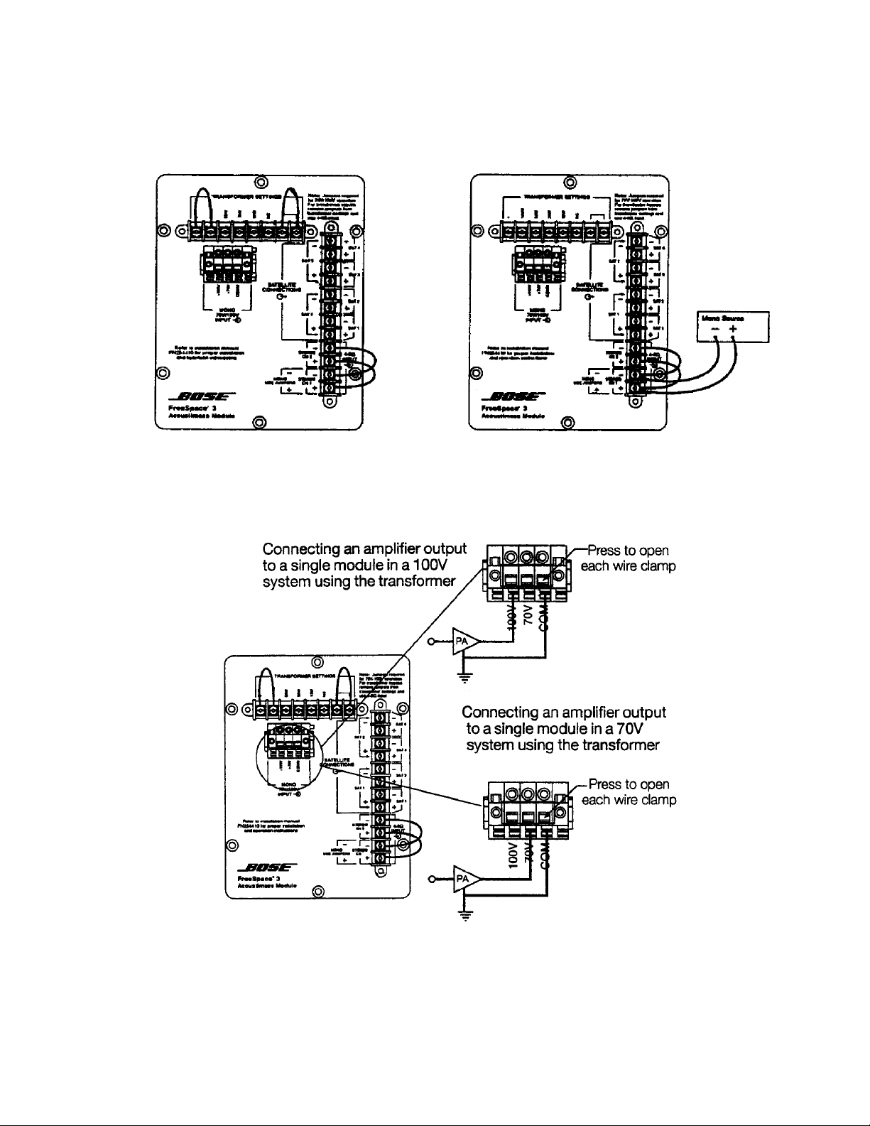
TEST SETUP PROCEDURES
Factory Default Settings 4 Ohm Test Setup Setting
70 and 100 Volt Setup Settings
Figure 2. Test Setup Diagrams
7
Page 8

TEST PROCEDURES
Note: The input voltage should be the
actual voltage present at the input, and not
the open circuit generator output.
Refer to the connection diagrams on page 6
for the proper connection configuration.
1. Bass Module Air Leak Test
Note: Use the 4 Ohm setup connection for
the following test procedures.
1.1 Apply a 6 Vrms, 50 Hz signal to mono
input terminals of the bass module. Do not
connect the satellite speakers.
1.2 Listen carefully for air leaks from
around the front and rear end caps, all
cabinet seams and the terminal plate. Air
leaks will be heard as a hissing or sputtering sound. Test duration should be 5 seconds minimum. All repairs must be hidden.
2. Woofer Phase Test
3. System Sweep Test
3.1 Set up the system as shown in
Figure 2 stereo setup settings.
3.2 Apply a 6 Vrms, 10 Hz signal to the
stereo input terminals of the bass module.
3.3 While listening to the output of the
system, sweep the input frequency slowly
from 10 Hz to 500 Hz. The output should
crossover from the bass module to the
satellites speakers.
Note: A whooshing noise from the bass
module port at around 40 Hz and 160 to
180 Hz is acceptable.
3.4 Reduce the input level to 3 Vrms.
3.5 Continue sweeping from 500 Hz to 15
kHz. Listen for a clean, undistorted output
from each satellite assembly. Replace any
satellite that buzzes or sounds distorted.
2.1 Apply a 6 Vrms, 50 Hz signal to the
stereo input terminals of the bass module.
2.2 While the signal is being applied to the
bass module, remove the input to one of
the stereo terminals.
2.3 The sound output level should drop by
approximately half. If the sound output level
increases, stays the same, or stops completely, then there is a wiring problem at the
crossover assembly or woofers.
Note: The FreeSpace® 3 bass module
woofer and satellite speakers are not
repairable. If you have a defective bass
module or satellite speaker, it must be
replaced.
4. 70/100 Volt Input Test Procedure
Note: This test is only to check that the
transformer connections are functioning.
4.1 Apply a 13 Vrms, 50 Hz signal to the 70
Volt input terminals.
4.2 Sweep the input frequency from 50 Hz
to 500 Hz.
4.3 Apply a 13 Vrms, 50 Hz signal to the
100 Volt input terminals.
4.4 Repeat procedure 4.2.
8
Page 9

MAIN PART LIST
Item
Description Part Number Qty. Note
Number
1 SCREW, #8-32 x .25, PA N, XREC 290303-04 4 4
2 NUT, HEX, 8-32, KEPS 118260-08 2 4
3 TRANSFORMER, AUTO, 100W 291091-001 1
4 PLATE, I/O 292292 1
5 GASKET, TERMINAL B LOCK 187460 1
6 SCREW, TAPP, 6-20, PAN, XREC - 4
7 SCREW, TAPP, 6-20, PA N, X RE C 290301-10 6 4
8 CONNECTOR, BARRIER, WR PINS 254416-08 1
9 CONNECTOR, BARRIER, WR PINS 254416-12 1
10 CONNECTOR, TERMINAL BLOCK STRIP 254416-03 1
11 SCREW, WOOD, 8-11x .7 5, FLAT, XREC 289388-012 10 4
12 CROSSOVER, ASSEMBLY 291027-001 1
13 GROMMET, GRILLE, . 635” 117995 6
14 NAMEPLATE, 1” , DIAMOND CUT, BLACK
NAMEPLATE, 1” , DIAMOND CUT, WHITE
15 GRILLE ASSEM BLY, SATELLITE, BLACK
GRILLE ASSEMBLY, SATELLITE, WHITE
16 SATELLITE AS SEMBLY, BLACK
SATELLITE AS SEMBLY, WHITE
- BRACKET, BASSBOX 184892 1
- SCREW, ¼ x 20, 3/4L, HEX 179114-12 4 4
193250-11
193250-12
192410-019
192410-029
250490-149
150490-159
2
2
2
16
15
X6
13
14
12
X6
11
9
8
10
X4
1
3
2
X2
6
5
X2
7
X4
Figure 3. FreeSpace 3® Bass Module Exploded View
9
4
Page 10

CROSSOVER ELECTRICAL PART LIST
Reference
Description Part Number Note
Reference
Description Part Number Note
Reference
Description Part Number Note
Reference
Description Part Number Note
Resistors
Designator
R11 5.1 OHM, WW, 5W 132105-5R1 4
R21 5.1 OHM, WW, 5W 132105-5R1 4
Capacitors
Designator
C10 100uF, EL, 85ºc, 50V, 20% 289958-101 4
C20 100uF, EL, 85ºc, 50V, 20% 289958-101 4
C11 10uF, EL, BP, 85ºc, 50V, 20% 290391-100 4
C21 10uF, EL, BP, 85ºc, 50V, 20% 290391-100 4
Inductors
Designator
L11 350 uH 292703-001 4
L21 350 uH 292703-001 4
Miscellaneous
Designator
PTC11 POLYSWITCH, 60V, 4mm 190348-110K 4
PTC21 POLYSWITCH, 60V, 4mm 190348-110K 4
10
Page 11

CROSSOVER MECHANICAL PART LIST
Item
Description Part Number Qty. Note
Number
L11, 12 SCREW, MACH, 4-40 x 1, PAN, XREC 103146-16 2
L11, 12 WASHER, FLAT, .141", # 5 108258-05 2
L11, 12 WASHER, FLAT, .125", # 4 108258-04 2
L11, 12 NUT, HEX, 4-40 103234-440 1
J3 CONN, TERMINAL, 9 POS, MALE 137489-09 2
J1, 2, 4 PIN, GROOVED, .52 X .34 X .045 291521-5234 4
Figure 4. Crossover Assembly View
11
Page 12

PACKAGING PART LIST
Refer to Figure 5
Item
Number
1 PACKING, CORNER POST, BASS MOD. 148044 1
2 BAG, POLY, 13.5 x 35 x 9.5 x 2.5 mil. 114522 1
3 PACKING, CORNER POST, BASS INSERT 148364 1
4 COVER ASSY., WHITE
COVER ASSY., BLACK
5 BUMPER, RECESSED, FOOT, .88” 142839 4
6 MANUAL, OWNER’S 252171 1
7 CARD, INFO,. WARRANTY, U.S. 181357 1
8 BROCHURE, ALL PRODUCTS 188898 1
9 COMMITMENT LETTER 251001 1
10 CARD, INFO,. WARRANTY, MULTI LANG. 181460 1
11 CLIP, WIRE 187523 1
12 INSTALLATION GUIDE, FS3 292335 1
13 BAG, POLY, 14.38 x 9.87 x 2 mil. 103351 1
14 CARTON 253808 1
15 PACKING INSERT 253809 1
16 BRACKET, WALLMOUNT 184891 1
17 CARTON, D/C 253811 1
18 BRACKET, SAT., PRO, BLACK 277466-001 2
19 SHEET, DEC OF CONF., PRO AM3 255623 1
20 CARTON, CHIPBOARD, SATELLITE, BLACK 250555-001 2
21 BAG, POLY, 10 x 12 x 2 mil 144677 2
- BRACKET, SAT, PRO, WHITE 277466-002 2
Description Part Number Qty. Note
187096-4
187096-5
1
21
2X
2
1
19
18
17
20
15
16
Figure 5. Packaging Exploded View
12
2X
3
4
56 7 8
10
11
12 13
14
9
Page 13

A
2. ALL CAPACITOR VALUES ARE EXPRESSED IN MICROFARADS.
1. ALL RESISTOR VALUES ARE EXPRESSED IN OHMS
NOTES:
UNLESS OTHERWISE SPECIFIED:
COM
4
COM
J2
J3
5W
10W
5
J3
J3
J3
70V
25W
7J36
100V
4J25J26
1J32J33
50W
8
B
J3
AUTOFORMER
100W
9
J3
C
CH2
PTC
+
3
J1
PTC21
21
-
4
J1
CH1
-
2
J1
PTC
21
D
+
1
J1
PTC11
4321
SD 254414
1234
SAFETY CONTROLLED
FRAMINGHAM, MA 01701-9168
PCB 254414
FreeSpace 3
R
J4
6
7J48
-
COM5W10W
350uH
J1
100uF
5.1
L11
J1
7
+SAT2
SATELLITE
OUTPUTS
R11
J1
6
-SAT1
C10
10uF
C11
J1
5
+SAT1
100uF
C20
350uH
L21
J4
J4
25W
J4
J4
1
2
3J44J45
100W
+
50W
J1
12
-SAT4
11
+SAT4
5.1
J1
10
-SAT3
SATELLITE
OUTPUTS
R21
J1
10uF
C21
J1
9
+SAT3
P3
P4
+WOOFVC2
-WOOFVC2
P1
P2
+WOOFVC1
-WOOFVC1
8
-SAT2
A
B
C
D
Figure 6. Crossover Assembly Schematic Diagram
13
Page 14

Date Revision
Description of Change Change
Pages
SERVICE MANUAL REVISION HISTORY
Level
7/00 00 Document released at
revision 00.
09/06 00 t o 01 Added RoHS part numbers This product is
1
Driven By
now built with
RoHS
compliant
parts.
Affected
8-11
Page 15

SPECIFICATIONS AND FEATURES SUBJECT TO CHANGE WITHOUT NOTICE
Bose Corporation
The Mountain
Framingham Massachusetts USA 01701
P/N: 256589 REV.01 04/2006 FOR TECHNICAL ASSISTANCE OR PART ORDERS, CALL 1-800-233-4408
 Loading...