

Page 1
PANARAY®System
S
Y
Stereo Bank
802 Full Range
-dB
L
R
40 24 18 12 6 0 O
PANARAY SYSTEM DIGITAL CONTROLLER
PRESET
LIMITER
UTILITY
DELAY
INPUT METER TPM
Digital Controller
Installation guide
TANDB
pro.bose.com
Page 2

2
Page 3

Table of Contents
Safety Information . . . . . . . . . . . . . . . . . . . . . . . . . . . . . . . . . . . . . . . . . . . . . . . . . . . 4
1.0 Introduction . . . . . . . . . . . . . . . . . . . . . . . . . . . . . . . . . . . . . . . . . . . . . . . . . . . . . . . . 8
2.0 Front Panel . . . . . . . . . . . . . . . . . . . . . . . . . . . . . . . . . . . . . . . . . . . . . . . . . . . . . . . . 9
3.0 Rear Panel . . . . . . . . . . . . . . . . . . . . . . . . . . . . . . . . . . . . . . . . . . . . . . . . . . . . . . . . 10
4.0 Signal Flow . . . . . . . . . . . . . . . . . . . . . . . . . . . . . . . . . . . . . . . . . . . . . . . . . . . . . . . . 11
4.1 Ch1 and Ch2 Inputs . . . . . . . . . . . . . . . . . . . . . . . . . . . . . . . . . . . . . . . . . . . . 12
4.2 EQ and Crossover . . . . . . . . . . . . . . . . . . . . . . . . . . . . . . . . . . . . . . . . . . . . . 13
4.3 2 x 4 Router . . . . . . . . . . . . . . . . . . . . . . . . . . . . . . . . . . . . . . . . . . . . . . . . . . 14
4.4 Delay and Limiter . . . . . . . . . . . . . . . . . . . . . . . . . . . . . . . . . . . . . . . . . . . . . . 15
5.0 PRESET Button. . . . . . . . . . . . . . . . . . . . . . . . . . . . . . . . . . . . . . . . . . . . . . . . . . . . . 16
5.1 Stereo Bank . . . . . . . . . . . . . . . . . . . . . . . . . . . . . . . . . . . . . . . . . . . . . . . . . . 17
5.1.1 Stereo Mid-High with Mono Bass . . . . . . . . . . . . . . . . . . . . . . . . . . . . . 18
5.2 Mono Bank . . . . . . . . . . . . . . . . . . . . . . . . . . . . . . . . . . . . . . . . . . . . . . . . . . . 19
5.3 Bass Array Bank . . . . . . . . . . . . . . . . . . . . . . . . . . . . . . . . . . . . . . . . . . . . . . . 20
5.4 Dual Mono Operation . . . . . . . . . . . . . . . . . . . . . . . . . . . . . . . . . . . . . . . . . . . 22
6.0 DELAY Button . . . . . . . . . . . . . . . . . . . . . . . . . . . . . . . . . . . . . . . . . . . . . . . . . . . . . . 24
7.0 LIMITER Button. . . . . . . . . . . . . . . . . . . . . . . . . . . . . . . . . . . . . . . . . . . . . . . . . . . . . 25
8.0 UTILITY Button . . . . . . . . . . . . . . . . . . . . . . . . . . . . . . . . . . . . . . . . . . . . . . . . . . . . . 26
8.1 User Lockout . . . . . . . . . . . . . . . . . . . . . . . . . . . . . . . . . . . . . . . . . . . . . . . . . 28
9.0 Router Functionality. . . . . . . . . . . . . . . . . . . . . . . . . . . . . . . . . . . . . . . . . . . . . . . . . . 29
10.0 Optimizing Signal-to-Noise. . . . . . . . . . . . . . . . . . . . . . . . . . . . . . . . . . . . . . . . . . . . . 31
11.0 Custom Preset Mode. . . . . . . . . . . . . . . . . . . . . . . . . . . . . . . . . . . . . . . . . . . . . . . . . 33
12.0 Bass Array Presets . . . . . . . . . . . . . . . . . . . . . . . . . . . . . . . . . . . . . . . . . . . . . . . . . . 34
12.1 Bass Array Setup and Connections. . . . . . . . . . . . . . . . . . . . . . . . . . . . . . . . . 35
®
13.0 Bose
14.0 Technical Information. . . . . . . . . . . . . . . . . . . . . . . . . . . . . . . . . . . . . . . . . . . . . . . . . 54
Speaker EQ Preset List . . . . . . . . . . . . . . . . . . . . . . . . . . . . . . . . . . . . . . . . . . 38
13.1 Mono Bank . . . . . . . . . . . . . . . . . . . . . . . . . . . . . . . . . . . . . . . . . . . . . . . . . . . 39
13.2 Stereo Bank . . . . . . . . . . . . . . . . . . . . . . . . . . . . . . . . . . . . . . . . . . . . . . . . . . 46
13.3 Bass Array Bank . . . . . . . . . . . . . . . . . . . . . . . . . . . . . . . . . . . . . . . . . . . . . . . 53
Appendix: PANARAY
®
System Digital Controller Quick-Reference Guide. . . . . . . . . . 55
3
Page 4

Important Safety Instructions
Warning (English)
To reduce the risk of fire or electric shock, do not expose the unit to rain or moisture.
CAUTION: TO REDUCE THE RISK OF ELECTRIC SHOCK,
DO NOT REMOVE COVER (OR BACK).
NO USER-SERVICEABLE PARTS INSIDE.
REFER SERVICING TO QUALIFIED PERSONNEL.
These CAUTION marks may be located on the back of the PANARAY
Digital Controller.
The lightning flash with arrowhead symbol, within an equilateral triangle, is intended to alert the user to the presence of uninsulated dangerous voltage within the system enclosure that may be of sufficient magnitude to constitute a risk of electric shock.
The exclamation point within an equilateral triangle, as marked on the
system, is intended to alert the user to the presence of important operating and maintenance instructions in this owner’s guide.
Important Safety Instructions
1. Read and follow these instructions.
2. Heed all warnings–on the product and in the owner’s guide.
3. Do not use this apparatus near water or moisture.
4. Clean only with a dry cloth.
5. Do not block any ventilation openings. Install in accordance with the
manufacturer’s instructions. To ensure reliable operation of the product
and to protect it from overheating, put the product in a position and location
that will not interfere with its proper ventilation.
6. Do not install near any heat sources, such as radiators, heat registers,
stoves, or other apparatus (including amplifiers) that produce heat.
7. Do not defeat the safety purpose of the grounding-type plug. A
grounding-type plug has two blades and a third grounding prong. The
third prong is provided for your safety. If the provided plug does not fit in
your outlet, consult an electrician for replacement of the outlet.
8. Protect the power cord from being walked on or pinched, particularly at
plugs, convenience receptacles, and the point where they exit from the
apparatus.
9. Only use attachments/accessories specified by the manufacturer.
10. Use only with a cart, stand, tripod, bracket or table specified by the
manufacturer or sold with the apparatus. When a cart is used, use
caution when moving the cart/apparatus combination to avoid injury
from tip-over.
11. Refer all servicing to qualified service personnel. Servicing is required
when the apparatus has been damaged in any way: such as power supply cord or plug is damaged; liquid has been spilled or objects have fall
en into the apparatus; the apparatus has been exposed to rain or moisture, does not operate normally, or has been dropped–Do not attempt to
service this product yourself. Opening or removing covers may expose you to
dangerous voltages or other hazards. Please call Bose
authorized service center near you.
12. To prevent risk of fire or electric shock, avoid overloading wall outlets,
extension cords, or integral convenience receptacles.
13. Do not let objects or liquids enter the product– as they may touch
dangerous voltage points or short-out parts that could result in a fire or
electric shock.
14. See product enclosure back for safety related markings.
15. No naked flame sources, such as lighted candles, should be placed on
the apparatus.
16. Product must be rack-mounted and installed in accordance with local building
codes.
17. Product is not intended for marine applications.
CAUTION
RISK OF ELECTRICAL SHOCK
DO NOT OPEN
®
System
®
to be referred to an
Advarsel (Dansk)
Enheden må ikke udsættes for regn eller fugtighed af hensyn til risikoen for brand
eller elektrisk stød.
FFORSIGTIGHEDOF
RISIKO FOR ELEKTRISK STØD
MÅ IKKE ÅBNES
FJERN IKKE LÅGET (ELLER BAGKLÆDNINGEN)
AF HENSYN TIL RISIKOEN FOR ELEKTRISK STØD.
DER ER INGEN DELE INDEN I, DER KAN SERVICERES
AF BRUGEREN. OVERLAD SERVICERINGEN
TIL KVALIFICERET PERSONALE.
®
Disse FORSIGTIGHEDSMÆRKER er anbragt på de PANARAY
Controller.
Symbolet med et lyn med pilespids i en ligesidet trekant skal gøre brugeren
opmærksom på tilstedeværelsen af en ikke-isoleret farlig spænding i det
lukkede system, der kan være tilstrækkelig kraftig til at give elektrisk stød.
Udråbstegnet i en ligesidet trekant, som systemet er mærket med, er beregnet til at advare brugeren om vigtige instruktioner til betjening og vedligeholdelse i denne betjeningsvejledning.
Vigtige sikkerhedsinstruktioner
1. Læs og følg disse instruktioner.
2. Læg mærke til alle advarsler - på produktet og i betjeningsvejledningen.
3. Anvend ikke dette apparat i nærheden af vand eller fugtighed.
4. Rengør kun med en tør klud.
5. Undgå at blokere ventilationsåbningerne. Installér i overensstemmelse med producentens instruktioner - Til sikring af pålidelig funktion og beskyttelse mod
overophedning skal produktet anbringes i en position og på et sted, der ikke hindrer korrekt ventilation.
6. Installér ikke i nærheden af varmekilder, såsom radiatorer, varmeovne, komfurer
eller andre apparater (herunder forstærkere) der frembringer varme.
7. Omgå ikke sikkerheden ved brug af et ikke jordforbundet stik. Et jordforbundet stik
har to ben og et tredje jordben. Det tredje ben er der af hensyn til din sikkerhed.
Hvis det medfølgende stik ikke passer i stikkontakten, skal du kontakte en elektriker for at få stikkontakten udskiftet.
8. Beskyt netledningen mod at blive trådt på eller klemt, specielt ved stik, stikkontakter og der, hvor den kommer ud af apparatet.
9. Brug kun tilslutningsudstyr/tilbehør, der er angivet af producenten.
10.Brug det kun sammen med en vogn, eller bord, der er angivet af producenten eller
solgt sammen med apparatet. Når der anvendes en vogn, skal der udvises forsigtighed ved kørsel med vogn/apparat, så det ikke vælter.
11. Overlad al serviceringen til kvalificeret servicepersonale. Service er påkrævet, hvis
apparatet på nogen måde er blevet beskadiget: f.eks. hvis netledningen eller
stikket er blevet beskadiget, der er blevet spildt væske eller faldet genstande ned i
apparatet, apparatet er blevet udsat for regn eller fugt, hvis det ikke fungerer normalt, eller hvis det er blevet tabt - forsøg ikke at reparere apparatet selv. Åbning
eller fjernelse af låget kan udsætte dig for farlige spændinger eller andre farer.
Kontakt Bose
12.Undgå at overbelaste stikkontakter, forlængerledninger eller indbyggede stik af
hensyn til risikoen for brand eller elektrisk stød.
13.Undgå at genstande eller væsker kommer ind i produktet, da de kan berøre steder
med farlige spændinger eller kortslutte dele, hvilket kan resultere i brand eller elektrisk stød.
14.Se på bagklædningen angående mærkater, der er relevante for sikkerheden.
15.Der må ikke anbringes åben ild såsom tændte lys på apparatet.
16.Produktet skal monteres i rack og installeres i henhold til lokale bygningsregler.
17.Produktet er ikke beregnet til marineprogrammer.
®
for at få oplysninger om det nærmeste servicecenter.
System Digital
4
Page 5
Important Safety Instructions
Vorsicht! (Deutsch)
Dieses Gerät darf weder Regen noch Feuchtigkeit ausgesetzt werden, damit Brände durch
Kurzschluss oder elektrische Schläge verhindert werden.
FVORSICHT!OF
STROMSCHLAGGEFAHR!
NICHT ÖFFNEN.
ACHTUNG! ZUR VERMEIDUNG VON ELEKTRISCHEN
SCHLÄGEN WEDER DIE ABDECKUNG NOCH DIE
RÜCKWAND ENTFERNEN. IM INNEREN BEFINDEN SICH
KEINE VOM BENUTZER ZU WARTENDEN TEILE.
WENDEN SIE SICH BEI NOTWENDIGEN REPARATUREN
AN QUALIFIZIERTES FACHPERSONAL.
Diese Sicherheitshinweise befinden sich auf der Rückseite des PANARAY®System DigitalController.
Das Blitzsymbol mit Pfeilspitze in einem gleichseitigen Dreieck soll den Benutzer
auf das Vorhandensein einer nichtisolierten gefährlichen elektrischen Spannung
innerhalb des Systemgehäuses hinweisen, die so hoch ist, dass eine Gefährdung
durch elektrische Schläge besteht.
Das Ausrufungszeichen in einem gleichseitigen Dreieck, wie es auf dem System
angebracht ist, soll den Benutzer auf wichtige Bedienungs- und
Wartungsanweisungen in dieser Bedienungsanleitung aufmerksam machen.
Wichtige Sicherheitshinweise
1. Lesen Sie die folgenden Sicherheitshinweise noch vor der Inbetriebnahme des
Geräts aufmerksam durch.
2. Beachten Sie alle Warn- und Sicherheitshinweise am Gerät und in dieser
Bedienungsanleitung.
3. Verwenden Sie dieses Gerät nicht in der Nähe von Wasser oder Feuchtigkeit.
4. Reinigen Sie das Gerät nur mit einem sauberen, trockenen Tuch.
5. Achten Sie darauf, dass die Lüftungsöffnungen nicht blockiert sind. Stellen Sie das
Gerät gemäß den Herstelleranweisungen auf. Stellen Sie es nur an einem Ort auf, an
dem eine gute Luftzirkulation gewährleistet ist, um den zuverlässigen Betrieb des
Geräts sicherzustellen und es gegen Überhitzung zu schützen.
6. Stellen Sie das Gerät nicht in der Nähe von Wärmequellen auf, wie Heizkörpern,
Wärmespeichern, Öfen oder anderen Geräten (auch Verstärkern), die Wärme erzeugen.
7. Beeinträchtigen Sie in keiner Weise die Schutzfunktion des Schutzkontaktsteckers. Ein
Schutzkontaktstecker hat zwei Stromkontakte und einen dritten Erdungskontakt. Dieser
Erdungskontakt dient Ihrer Sicherheit. Falls der mitgelieferte Schutzkontaktstecker nicht
n Ihre Steckdose passt, wenden Sie sich an einen qualifizierten Elektriker, um die
Steckdose auszutauschen.
8. Verlegen Sie das Netzkabel so, dass es keine Stolpergefahr darstellt und nicht
beschädigt werden kann - insbesondere im Bereich von Steckern und Steckdosen und
dort, wo das Netzkabel aus dem Gerät herausgeführt wird.
9. Verwenden Sie nur Zubehör-/Anbauteile, die vom Hersteller zugelassen sind.
10.Verwenden Sie für das Gerät nur Rollwagen, Ständer, Dreibeine, Halterungen oder
Tische, die vom Hersteller zugelassen sind oder zusammen mit dem Gerät verkauft werden. Falls Sie einen Rollwagen verwenden, dürfen Sie die Einheit Gerät/Rollwagen nur
mit Vorsicht bewegen, damit Verletzungen beim möglichen Umkippen ausgeschlossen
sind.
11.Wenden Sie sich bei allen Reparatur- und Wartungsarbeiten nur an qualifiziertes
Kundendienstpersonal. Eine Reparatur ist erforderlich, wenn das Gerät in irgendeiner
Weise beschädigt wurde: Beispielsweise falls das Netzkabel oder der Netzstecker
beschädigt ist, Flüssigkeit oder Fremdkörper in das Gerät gelangt sind oder das Gerät
Regen bzw. Feuchtigkeit ausgesetzt war, nicht einwandfrei arbeitet oder heruntergefall
en ist. Versuchen Sie in solchen Fällen keinesfalls, das Gerät selbst zu reparieren. Öffnen oder entfernen Sie unter keinen Umständen Gehäuseabdeckungen, da Sie andern
falls mit gefährlichen elektrischen Spannungen in Berührung kommen oder anderen
Gefahren ausgesetzt sein könnten. Wenden Sie sich telefonisch an Bose
Anschrift eines autorisierten Kundendienstzentrums in Ihrer Nähe zu erfragen.
12.Vermeiden Sie Gefahren durch Brände oder elektrische Schläge, indem Sie Steckdosen,
Verlängerungskabel und integrierte Gerätesteckdosen nicht überlasten.
13.Lassen Sie keine Flüssigkeiten oder Fremdkörper in das Gerät gelangen - sie können
unter gefährliche elektrische Spannung gesetzt werden oder Bauteile kurzschließen und
folglich Brände und elektrische Schläge auslösen.
14.Beachten Sie die Sicherheitshinweise auf der Geräterückseite.
15.Stellen Sie keine offenen Flammen, wie brennende Kerzen, auf das Gerät.
16.Rack-Einbau und Installation des Produkts müssen in Übereinstimmung mit den vor Ort
geltenden Bauordnungen erfolgen.
17.Das Produkt ist nicht für den Einsatz in Wassernähe bestimmt.
®
, um die
Advertencia (Español)
Con el fin de reducir el riesgo de descarga eléctrica, no exponga la unidad a lluvia o
humedad.
FPRECAUCIÓNF
RIESGO DE DESCARGA ELÉCTRICA
PRECAUCIÓN: PARA REDUCIR EL RIESGO DE DESCARGA
ELÉCTRICA, NO QUITE LA CUBIERTA (O LA PARTE TRASERA).
EL INTERIOR NO CONTIENE COMPONENTES REPARABLES
POR EL USUARIO. PARA REPARACIONES,
LLEVE EL APARATO A PERSONAL CUALIFICADO.
Estas marcas de PRECAUCIÓN podrian estar situadas en la parte trasera del Controlador
Digital para Systemas PANARAY
El símbolo de un relámpago con una flecha, dentro de un triángulo equilátero,
avisa al usuario que dentro de la caja del sistema puede haber voltaje de una
magnitud suficiente para constituir un riesgo de descarga eléctrica.
El signo de exclamación dentro de un triángulo equilátero, según las marcas en el
sistema, sirven para avisar al usuario de que existen instrucciones de operación y
mantenimiento importantes en esta guía del usuario.
Importantes instrucciones de seguridad
1. Lea y siga estas instrucciones.
2. Respete todos los avisos – del producto y de la guía del usuario.
3. No utilice este aparato cerca del agua o humedad.
4. Limpie sólo con un trapo seco.
5. No bloquee las aperturas de ventilación. Instale según las instrucciones del fabricante
– Para garantizar que el producto funciona de manera fiable y con el fin de evitar que
se sobrecaliente, coloque el producto en una posición y ubicación que no interfiera con
su ventilación adecuada.
6. No lo instale cerca de fuentes de calor, tales como radiadores, salidas de aire caliente,
hornos o demás aparatos (inclusive amplificadores), que generen calor.
7. No elimine el dispositivo de seguridad ofrecido por el enchufe con toma a tierra. Los
enchufes con toma a tierra tienen dos patas para la corriente, y una tercera para la
toma de tierra. La tercera pata está instalada a efectos de seguridad. Si el enchufe
suministrado no encaja en sus tomas de electricidad, consulte con un electricista para
sustituirlo.
8. Proteja el cable eléctrico de forma que nadie lo pise o quede apretado, particularmente
cerca de los enchufes, receptáculos de tomas múltiples, y en el lugar en el que sale del
aparato.
9. Utilice sólo conexiones y accesorios suministrados por el fabricante.
10.Utilice sólo con un carrito, soporte, trípode, abrazadera o mesa suministrados por el fabricante o vendidos junto al aparato. Cuando se utilice un carrito, tenga cuidado al mover
la combinación de carrito/aparato para evitar lesiones en caso de que se caiga.
11.Toda reparación debe ser realizada por personal cualificado. Lleve el aparato a reparar
si éste sufre cualquier daño, como por ejemplo: si el cable eléctrico o enchufe están
dañados, se ha derramado líquido o han caído objetos dentro del aparato; el aparato ha
sido expuesto a la lluvia o a la humedad, no funciona normalmente, o ha caído – No
intente reparar este producto usted mismo. Abrir o sacar las tapas le expondrá a volta
jes peligrosos o a otros peligros. Por favor llame a Bose
tro de reparación autorizado en su zona.
12.Para impedir el riesgo de descarga eléctrica, evite la sobrecarga de los enchufes,
cables de extensión o receptáculos de varias tomas.
13.No deje que caigan objetos o líquidos dentro del aparato – ya que podrían tocar puntos
en los que existen niveles de voltaje peligrosos, o causar cortocircuitos que podrían
causar incendios o descargas eléctricas.
14.Vea la parte posterior de la caja para indicaciones de seguridad.
15.No coloque en el aparato ninguna llama viva, como por ejemplo una vela.
16.El producto se debe montar en bastidor y debe instalarse según los códigos de montaje
locales.
17.El producto no está pensado para aplicaciones marinas.
®
NO ABRIR
®
para que le indiquen un cen-
5
Page 6
Important Safety Instructions
Avertissement (Français)
Afin de réduire le risque d’incendie ou de choc électrique, ne pas exposer le système à la
pluie ou à l’humidité.
ATTENTION
RISQUE DE CHOC ELECTRIQUE
NE PAS OUVRIR
ATTENTION : AFIN DE REDUIRE LE RISQUE DE CHOC
ELECTRIQUE, NE PAS RETIRER LE CAPOT DE L’APPAREIL
(OU SON PANNEAU ARRIÈRE). IL N’EXISTE A L’INTERIEUR
DE CET EQUIPEMENT AUCUN ELEMENT OU
SOUS-ENSEMBLE POUVANT ETRE DEPANNE PAR
L’UTILISATEUR. LA MAINTENANCE DOIT ETRE
REALISEE PAR UN PERSONNEL QUALIFIE.
Ces signalisations d’AVERTISSEMENT sont peut-être situées à l’arrière del PANARAY
System Digital Controller
L’éclair terminé par une flèche et contenu dans un triangle équilatéral est prévu
pour attirer l’attention de l’utilisateur sur la présence à l’intérieur du produit, de
tensions dangereuses appliquées à certains éléments non protégés. Ces tensions
sont d’une magnitude suffisamment importante pour constituer un risque de choc
électrique ou d’électrocution.
Le point d’exclamation contenu dans un triangle équilatéral est prévu pour avertir
l’utilisateur sur la présence d’instructions importantes de fonctionnement ou de
maintenance (sur le produit et dans ce manuel).
Consignes de sécurité importantes
1. Lisez et appliquez les instructions données dans ce document.
2. Soyez attentif à tous les avertissements—Ceux figurant sur l’appareil et ceux délivrés
dans ce guide.
3. N’utilisez pas cet appareil à proximité d’eau ou d’humidité.
4. Pour le nettoyage, utilisez un chiffon sec.
5. N’obstruez aucun des orifices de ventilation. Choisissez un emplacement conforme
aux instructions du fabricant—Pour assurer le bon fonctionnement de l’appareil et le
protéger contre tout risque de surchauffe, placez celui-ci à un endroit et dans une
position qui ne compromette pas sa ventilation.
6. Ne posez pas l’appareil à proximité de sources de chaleur telles que : radiateurs,
bouches de chauffage pulsé, poêle ou autres appareils (amplificateurs y compris)
dégageant de la chaleur.
7. Pour votre sécurité, ne débranchez pas la liaison de terre sur la prise secteur. Cette
prise comporte deux broches mâles et une broche femelle de mise à la terre. Cette
dernière sert à vous protéger. Si la fiche équipant votre appareil ne correspond pas à
votre prise secteur murale, faites appel à un électricien qualifié pour qu’il effectue son
remplacement.
8. Evitez que le cordon d’alimentation ne soit piétiné ou pincé, en particulier au niveau
de la prise, d’un bloc multiprises ou de sa sortie de l’appareil.
9. N’utilisez que les accessoires préconisés par le fabricant.
10.N’utilisez qu’un rack, un meuble, un support ou une table préconisé par le fabricant
ou vendu pour être utilisé avec l’appareil. Si l’appareil est placé à l’intérieur d’un rack,
déplacez celui-ci avec prudence afin d’éviter qu’il n’occasionne des blessures en se
renversant.
11. Faites effectuer tous les travaux d’entretien ou de réparation par un personnel qualifié. Une maintenance est nécessaire dès que l’appareil est endommagé de manière
quelconque, notamment lorsque le cordon d’alimentation est en mauvais état, qu’un
liquide a été renversé ou qu’un objet est tombé à l’intérieur du produit. Il en va de
même si l’équipement a été exposé à la pluie ou à l’humidité, qu’il est tombé ou qu’il
ne fonctionne pas normalement—N’essayez pas de réparer cet appareil vous-même.
En ouvrant ou en retirant un capot, vous risquez d’entrer en contact avec des tensions dangereuses ou de vous retrouver exposé à d’autres dangers. Appelez la
société Bose
vous.
12.Pour éviter tout risque d’incendie ou de choc électrique, ne surchargez pas les prises
murales, les prolongateurs ou les blocs multiprises.
13.Evitez que des objets ou des liquides ne pénètrent dans l’appareil. Ils pourraient entrer
en contact avec des éléments alimentés par des tensions dangereuses ou créer
des courts-circuits pouvant provoquer un incendie ou une électrocution.
14.Reportez-vous aux avertissements relatifs à la sécurité, apposés à l’arrière du
châs<None><None>sis.
15.Ne placez aucune flamme nue, telle qu’une bougie, sur l’appareil.
16.L’appareil doit être monté sur rack et installé conformément aux réglements locaux du
bâtiment.
17.L’appareil n’est pas destiné à être utilisé sur un bateau.
®
afin de connaître la station technique agréée la plus proche de chez
®
Avvertenza (Italiano)
Per ridurre il pericolo di incendi o scosse elettriche, non esporre l’apparecchio alla
pioggia o all’umidità.
ATTENZIONE
PERICOLO DI SCOSSE ELETTRICHE
ATTENZIONE: PER RIDURRE IL PERICOLO DI SCOSSE
ELETTRICHE, NON RIMUOVERE IL COPERCHIO (O IL
PANNELLO POSTERIORE). NON SONO PRESENTI PARTI
SOSTITUIBILI DALL’UTENTE. PER L’ASSISTENZA
CONTATTATE IL PERSONALE QUALIFICATO.
I seguenti simboli di AVVERTENZA sono apposti sul pannello posteriore del
®
PANARAY
System Digital Controller.
Il simbolo del fulmine all’interno di un triangolo equilatero ha lo scopo di
avvertire gli utenti della presenza di tensione pericolosa non isolata all’interno
dell’apparecchio, il cui livello è tale da costituire un potenziale rischio di scossa elettrica.
Il simbolo del punto esclamativo all’interno del triangolo equilatero, riportato
sull’apparecchio, ha lo scopo di informare gli utenti della presenza di importanti istruzioni di funzionamento e manutenzione nella documentazione fornita con il prodotto.
Importanti norme di sicurezza
1. Leggete attentamente le istruzioni riportate di seguito.
2. Prestate attenzione alle avvertenze riportate sull’apparecchio e nel manuale di
istruzioni.
3. Non utilizzate questo apparecchio vicino a fonti di umidità o acqua.
4. Utilizzate esclusivamente un panno asciutto per pulire l’apparecchio.
5. Non ostruite le aperture di ventilazione. Installate l’apparecchio conformemente a
quanto indicato nelle istruzioni fornite dal produttore. Al fine di garantire il corretto
funzionamento del prodotto e di proteggerlo da un riscaldamento eccessivo, collocate l’apparecchio in una posizione tale da non ostacolarne la corretta aerazione.
6. Non installate l’apparecchio vicino a fonti di calore, quali radiatori, stufe o altri apparati (compresi gli amplificatori) che generano calore.
7. Non manomettete la spina dotata di massa (Shuko), progettata per la vostra
sicurezza. Una spina Shuko è composta da due terminali e da un terzo terminale a
forca per la massa aggiunto per garantire un più elevato livello di sicurezza. Se la
spina fornita in dotazione non è adatta alle vostre prese a muro, contattare un tecnico per sostituire le prese.
8. Collocate il cavo di alimentazione in modo da evitare che venga calpestato o piega
to, in particolare in corrispondenza delle spine, delle prese multiple e dei punti dove
questo esce dall’apparecchio.
9. Utilizzate esclusivamente gli accessori specificati dal produttore.
10.Utilizzate esclusivamente con supporti mobili, piedistalli, staffe o ripiani specificati
dal produttore o forniti in dotazione con l’apparecchio. Quando utilizzate un supporto mobile, prestate attenzione durante gli spostamenti dell’insieme carrello/apparecchio per evitare danni fisici causati da un possibile ribaltamento.
11. Per le riparazioni rivolgetevi al personale di assistenza qualificato. Contattate il
servizio di assistenza nel caso l’apparecchio presenti danni di qualsiasi tipo, ad
esempio al cavo di alimentazione o alla spina oppure dovuti alla penetrazione di liq
uido o di altro materiale all’interno dell’apparecchio, all’esposizione dell’apparecchio
alla pioggia o all’umidità, a malfunzionamenti o, infine, a caduta. Non tentate di
riparare da soli il prodotto. L’apertura o la rimozione del coperchio potrebbe esporre
l’utente a tensioni pericolose o ad ulteriori rischi. Vi suggeriamo di contattare la
®
Bose
per informazioni relative al centro di assistenza autorizzato più vicino.
12.Per prevenire il pericolo di incendi o scosse elettriche, evitate il sovraccarico delle
prese a muro, delle prolunghe o delle prese multiple di corrente.
13.Prestate attenzione che del liquido o altro materiale non penetri all’interno del
prodotto poiché potrebbe venire a contatto con parti sotto tensione o soggette a cortocircuito con conseguente possibilità di incendi o di scosse elettriche.
14.I marchi delle certificazioni di sicurezza sono apposti sul pannello posteriore del
prodotto.
15.Non avvicinate all’apparecchio alcun tipo di fiamma, ad esempio un candeliere
acceso.
16.Il prodotto deve essere montato in rack e installato in linea con le disposizioni vigen
ti in materia edilizia.
17.Il prodotto non è adatto per l’utilizzo in ambito marittimo.
NON APRIRE
6
Page 7

Important Safety Instructions
1. Read these instructions.
2. Keep these instructions – for future reference.
3. Heed all warnings – on the product and in the
owner’s guide.
4. Follow all instructions.
5. Do not use this apparatus near water or moisture.
6. Clean only with a dry cloth.
7. Do not block any ventilation openings. Install in accordance with the manufacturer’s instructions – To
ensure reliable operation of the product and to protect
it from overheating, put the product in a position and
location that will not interfere with its proper ventilation.
8. Do not install near any heat sources, such as radiators, heat registers, stoves or other apparatus (including amplifiers) that produce heat.
9. Do not defeat the safety purpose of the polarized or
grounding-type plug. A polarized plug has two blades
with one wider than the other. A grounding-type plug
has two blades and a third grounding prong. The
wider blade or third prong are provided for your safety. If the provided plug does not fit in your outlet,
consult an electrician for replacement of the obsolete
outlet.
10. Protect the power cord from being walked on or
pinched, particularly at plugs, convenience receptacles, and the point where they exit from the apparatus.
11. Only use attachments/accessories specified by the
manufacturer.
12. Use only with the cart, stand, tripod, bracket or table specified by the manufacturer or
sold with the apparatus. When a cart is
used, use caution when moving the
cart/apparatus combination to avoid injury from tipover.
13. Unplug this apparatus during lightning storms or when
unused for long periods of time – to prevent damage
to this product.
14. Refer all servicing to qualified service personnel.
Servicing is required when the apparatus has been
damaged in any way: such as power-supply cord or
plug is damaged; liquid has been spilled or objects
have fallen into the apparatus; the apparatus has been
exposed to rain or moisture, does not operate normally, or has been dropped – Do not attempt to service
this product yourself. Opening or removing covers may
expose you to dangerous voltages or other hazards.
Please call Bose®to be referred to an authorized service center near you.
15. To prevent risk of fire or electric shock, avoid over
loading wall outlets, extension cords, or integral
convenience receptacles.
16. Do not let objects or liquids enter the product – as
they may touch dangerous voltage points or shortout parts that could result in a fire or electric shock.
17. See product enclosure back for safety related
markings.
18. No naked flame sources, such as lighted candles,
should be placed on the apparatus.
Information about products that generate
electrical noise
This equipment has been tested and found to comply
with the limits for a Class A digital device, pursuant to
Part 15 of the FCC rules. These limits are designed to
provide reasonable protection against harmful interference in a residential installation. This equipment generates, uses, and can radiate radio frequency energy and,
if not installed and used in accordance with the instructions, may cause harmful interference to radio communications. However, this is no guarantee that interference
will not occur in a particular installation. If this equipment
does cause harmful interference to radio or television
reception, which can be determined by turning the equipment off and on, you are encouraged to try to correct the
interference by one or more of the following measures:
• Reorient or relocate the receiving antenna.
• Increase the separation between the equipment and
receiver.
• Connect the equipment to an outlet on a different circuit than the one to which the receiver is connected.
• Consult the dealer or an experienced radio/TV technician for help.
Note: Unauthorized modification of the receiver or radio
remote control could void the user’s authority to operate
this equipment.
This product complies with the Canadian ICES-003 Class
A specifications.
7
Page 8

1.0 Introduction
S
Y
COM
Thank you for purchasing the Bose®PANARAY®system digital controller.
The PANARAY system digital controller uses a digital signal processing (DSP) architecture to provide
smooth, accurate spectral response for Bose professional loudspeakers that require active equalization.
Bose professional loudspeaker EQ can be applied by simply selecting the appropriate preset and configuration. No additional programming is required.
The PANARAY system digital controller has two balanced XLR analog inputs and four balanced XLR
analog outputs. It can be configured to run two mono Bose speaker EQ presets or a single stereo Bose
speaker EQ preset (including preset crossover settings).
There are a total of 180 presets, which are separated into Stereo, Mono, and Bass Array Banks. All routing is automatic, based on the selected preset and configuration. See the preset chart in section 13.0 for
a full list of presets with descriptions and output routing defaults.
In addition to providing Bose speaker equalization, the PANARAY system digital controller also has the
following easy-to-use programmable features:
• Four independent programmable line delays (200 ms per output) that can be used for decentralized or
distributed speaker alignment and for creating custom bass arrays.
• Four independent programmable output limiters that can be set to protect speakers from unpredictable
spikes in program material.
• Programmable signal router that allows each output to select Full Range, High Pass, Low Pass or
Bypass EQ combinations of input signals.
TANDB
INPUTS
CH1/MONO
CH2
8
INPUT METER TPM
L
-dB
40 24 18 12 6 0 O
R
CH1
Stereo Bank
802 Full Range
OUTPUTS
CH2 CH3
PRESET
LIMITER
DELAY
UTILITY
CH4
PANARAY SYSTEM DIGITAL CONTROLLER
Bose Corporation, Framingham, MA 01701-9168
Made in the U.S.A.
RISK OF ELECTRICAL
RISQUE DE CHOC ELECTRIQUE
DO NOT OPEN
NE PAS OUVRIR
POWER
100-240V~AC
50-60Hz
300W MAX
Page 9
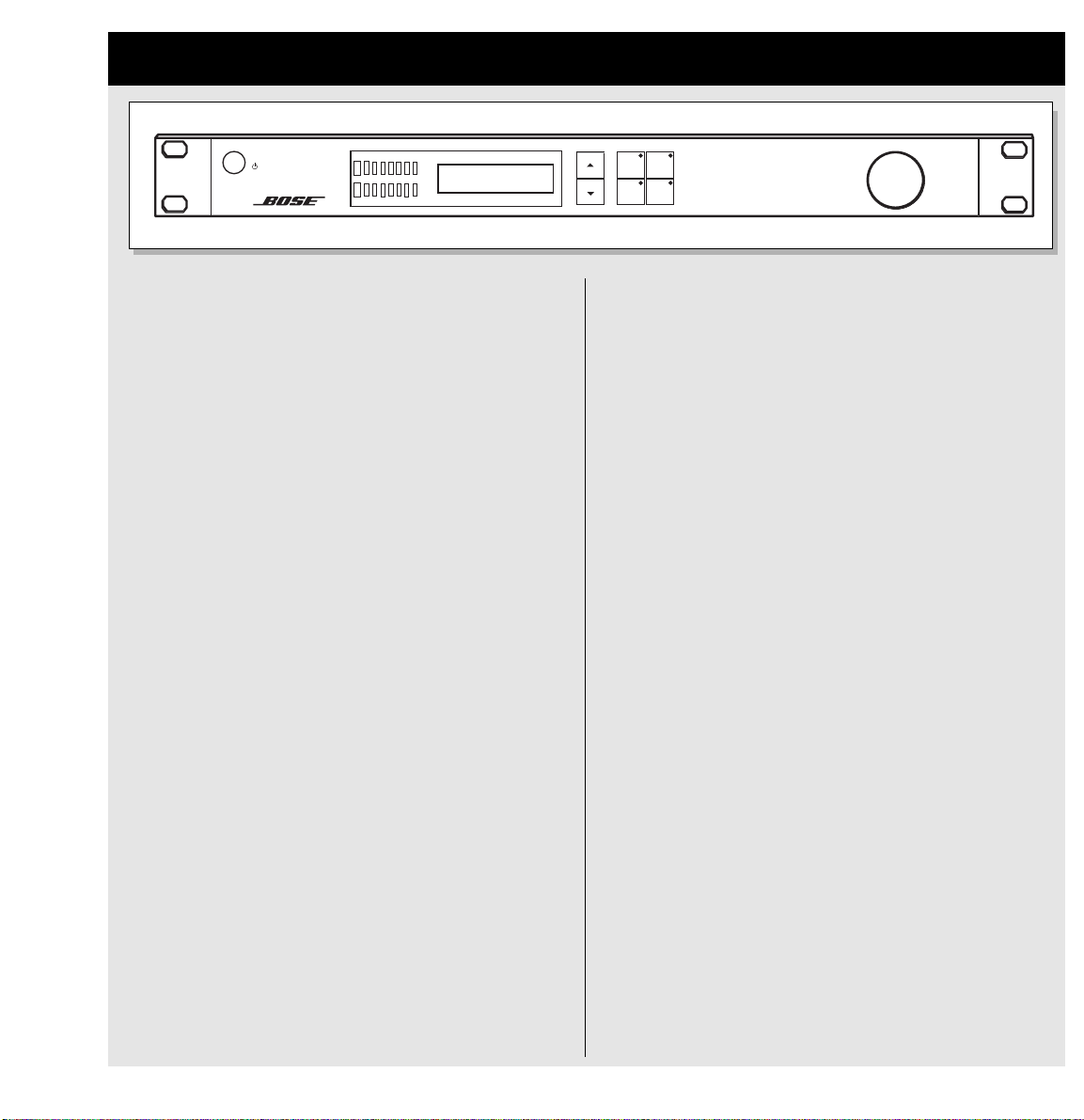
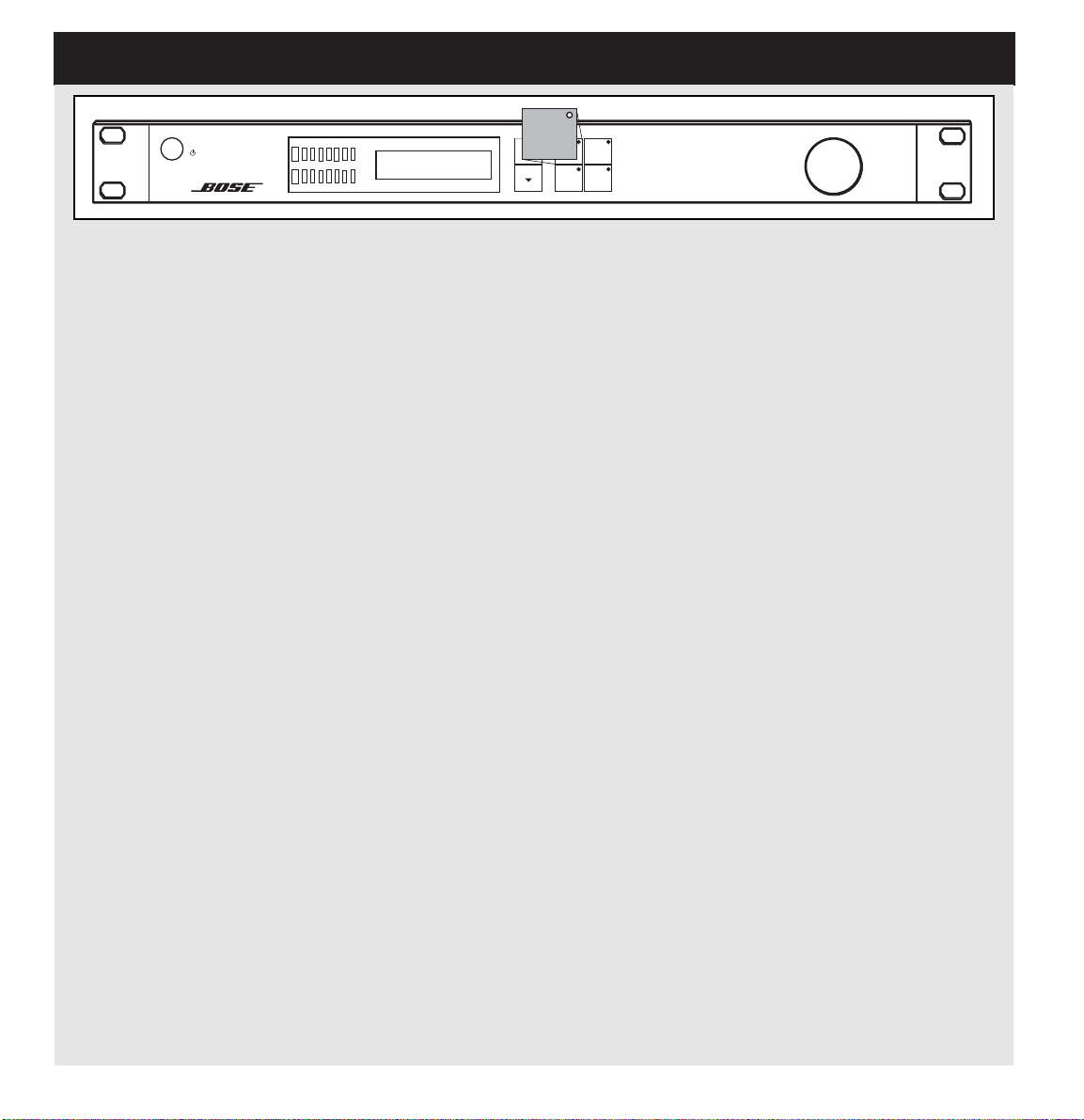
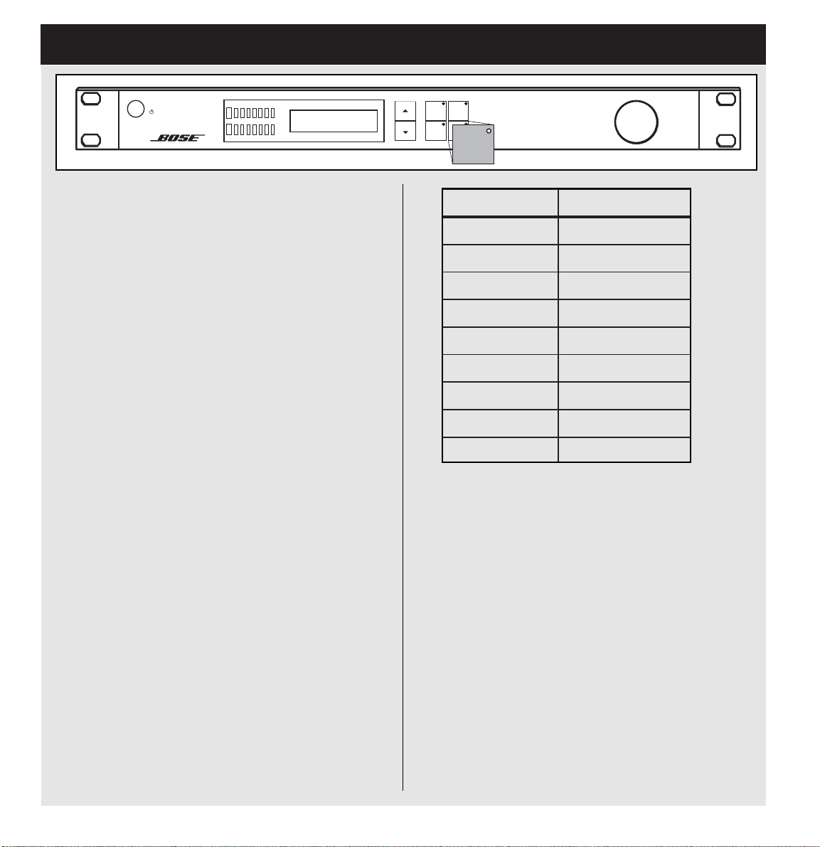
2.0 Front Panel
S
Y
TANDB
INPUT METER TPM
L
-dB
40 24 18 12 6 0 O
R
Stereo Bank
802 Full Range
STANDBY button:
Standby on/off
Input Meters:
The peak meter shows the input level of left
and right channels. The meter range is:
O (Overload), 0, -6, -12, -24, -40dB
Overload LEDs:
The Overload LEDs indicate one of two
situations.
• The input level is clipping (you will hear it).
• There is an internal DSP overflow.
The Overload LED is lit when one sample is
at 0 dBFS.
Display:
The 2 x 16 LCD displays Preset names,
parameter names, and values depending on
the mode of operation.
PRESET
LIMITER
DELAY
UTILITY
PANA RAY SYSTEM DIGITAL CONTROLLER
PRESET Button:
Press to enter preset mode, which pro-
®
vides access to Bose
speaker EQ pre-
sets.
LIMITER Button:
Press to access output limiter parameters.
UTILITY Button:
Press to access ROUTING, LEVEL and
general SYSTEM parameters.
DELAY Button:
Press to access output delay parameters.
Encoder Wheel:
Selects presets and changes parameter
values.
Arrow UP Button:
Press to navigate up through the user interface.
Arrow DOWN Button:
Press to navigate down through the user
interface.
9
Page 10

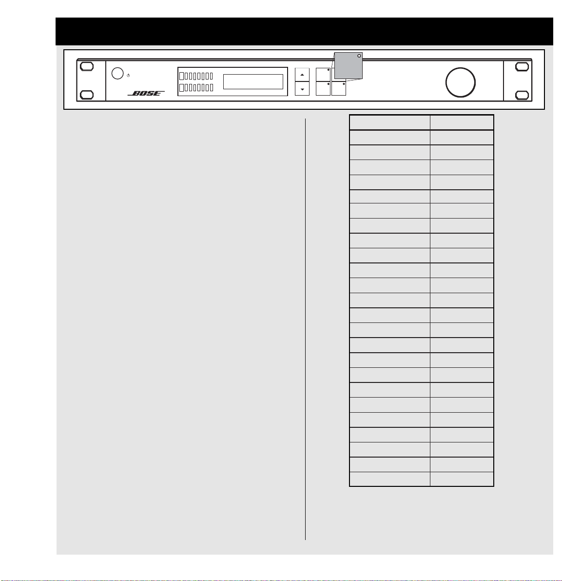
3.0 Rear Panel
COM
CH1/MONO
INPUTS
CH1
CH2
OUTPUTS
CH2 CH3
Balanced XLR Inputs:
Two balanced XLR inputs
Balanced XLR Outputs:
Four balanced XLR outputs
COM Port:
5-pin DIN that will be used for future
software upgrades or for adding new
®
speaker EQ presets
Bose
Power Input:
100-240VAC switching power supply
input
CH4
Bose Corporation, Framingham, MA 01701-9168
Made in the U.S.A.
RISK OF ELECTRICAL
RISQUE DE CHOC ELECTRIQUE
DO NOT OPEN
NE PAS OUVRIR
POWER
100-240V~AC
50-60Hz
300W MAX
TIP
RING
GND
Jack (balanced) - XLR
Sleeve - Pin 1 (Ground)
Tip - Pin 2 (Hot)
Ring - Pin 3 (Cold)
3
2
1
XLR Wiring
Jack (balanced) - XLR
Sleeve - Pin 1 (Ground)
Tip - Pin 2 (Hot)
Ring - Pin 3 (Cold)
+ Hot
– Cold
Ground
10
Page 11
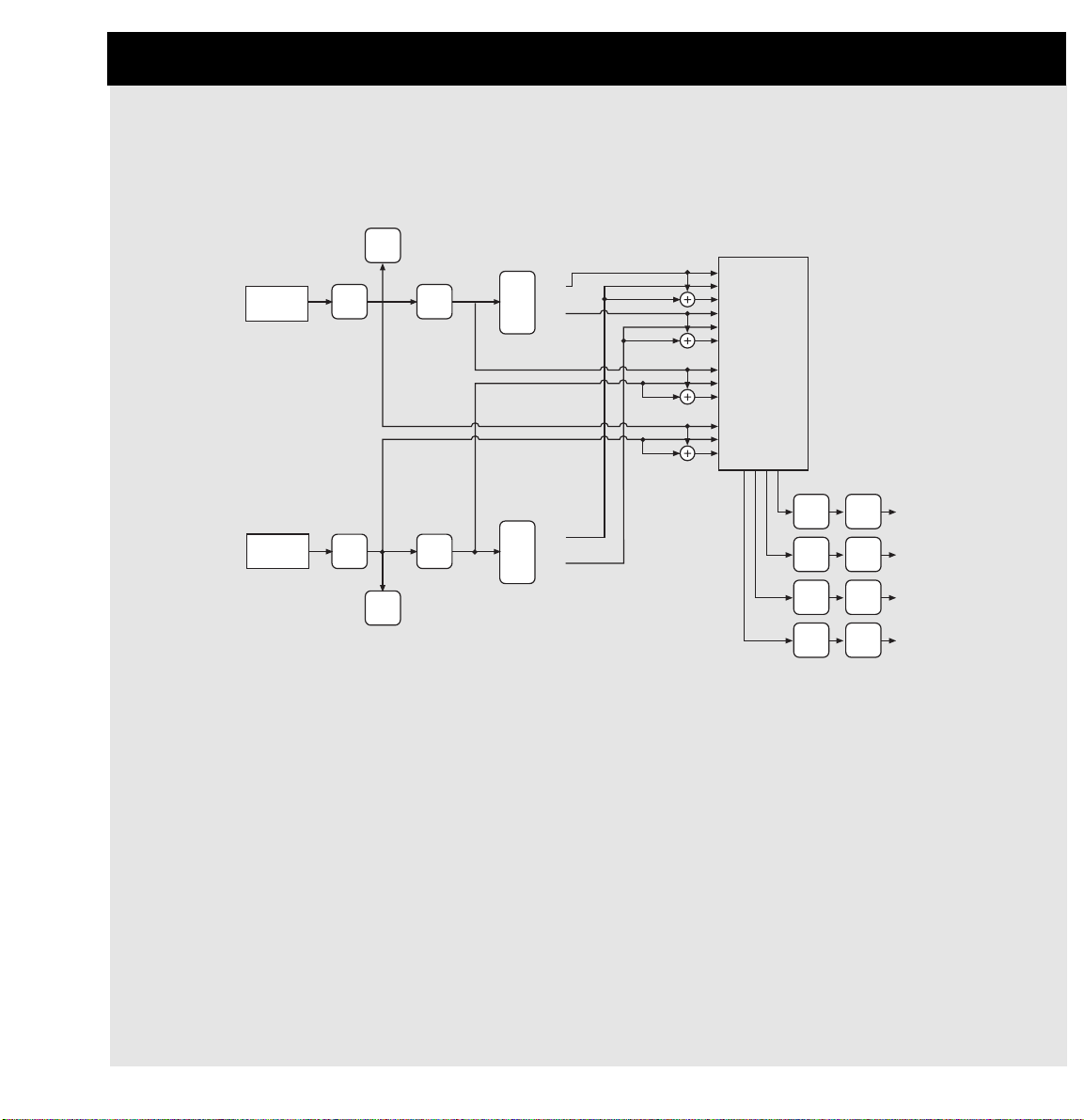
4.0 Signal Flow
The PANARAY®system digital controller has the ability to run a single stereo preset, a single mono preset, or
to run in dual mono mode. In the following section, the controller’s signal flow is broken down to provide a
better understanding of its full functionality.
Input
Meter
1 CH1 High
Input CH1
Input CH2
Input
trim
Input
trim
Input
meter
EQ
CH1
EQ
CH2
Xover
CH1
Xover
CH2
High
Low
High
Low
2 CH2 High
3 Mono High
4 CH1 Low
5 CH2 Low
6 Mono Low
7 CH1 FR
8 CH2 FR
9 Mono FR
10 CH1 No EQ
11 CH2 No EQ
12 Mono No EQ
Delay
line
Delay
line
Delay
line
Delay
line
Limiter
Limiter
Limiter
Limiter
Output 4
Output 3
Output 2
Output 1
Stereo Operation: When a preset is loaded from the stereo bank, the EQ/crossover blocks both process
each input the same way, meaning that the parameters are “linked”. The signal then passes through the router
section where the CH1 and CH2 inputs are sent to independent output channels for stereo operation.
Mono Operation: When a preset is loaded from the mono bank, the EQ/crossover blocks both process each
input the same way, meaning that the parameters are “linked”. The signal then passes through the router section where the CH1 and CH2 inputs are summed to mono. The controller has the ability to sum a stereo signal
to mono, or, it can process a single input for mono operation. Audio information is routed to the same outputs
regardless of the number of inputs that are connected.
®
Dual Mono Operation: When the PANARAY
system digital controller is used in dual mono mode, the
EQ/crossover blocks process each input independently – allowing the user to run two independent speaker
EQs. The router also processes each input independently, so each output is discrete.
11
Page 12

4.1 Signal Flow – CH1 and CH2 Inputs
1. CH1 and CH2 Inputs
Meter
Input CH1
Input CH2
Input
trim
Input
trim
meter
Input
Input
EQ
CH1
EQ
CH2
Xover
CH1
Xover
CH2
High
Low
High
Low
1 CH1 High
2 CH2 High
3 Mono High
4 CH1 Low
5 CH2 Low
6 Mono Low
7 CH1 FR
8 CH2 FR
9 Mono FR
10 CH1 No EQ
11 CH2 No EQ
12 Mono No EQ
Delay
line
Delay
line
Delay
line
Delay
line
Limiter
Limiter
Limiter
Limiter
Output 4
Output 3
Output 2
Output 1
1. CH1 and CH2 Input Section:
A stereo, mono, or dual mono signal passes through the input section.
12
Page 13

Input CH1
Input CH2
4.2 Signal Flow – EQ and Crossover
2. EQ and Crossover
Input
Meter
1 CH1 High
Input
trim
Input
trim
Input
meter
EQ
CH1
EQ
CH2
Xover
CH1
Xover
CH2
High
Low
High
Low
2 CH2 High
3 Mono High
4 CH1 Low
5 CH2 Low
6 Mono Low
7 CH1 FR
8 CH2 FR
9 Mono FR
10 CH1 No EQ
11 CH2 No EQ
12 Mono No EQ
Delay
line
Delay
line
Delay
line
Delay
line
Limiter
Limiter
Limiter
Limiter
Output 4
Output 3
Output 2
Output 1
2. EQ and Crossover:
Next, the program material passes through the EQ and crossover section.
13
Page 14

4.3 Signal Flow – 2 x 4 Router
3. 2 x 4 Router
1 CH1 High
2 CH2 High
3 Mono High
4 CH1 Low
5 CH2 Low
6 Mono Low
7 CH1 FR
8 CH2 FR
9 Mono FR
10 CH1 No EQ
11 CH2 No EQ
12 Mono No EQ
Delay
line
Delay
line
Delay
line
Delay
line
Limiter
Limiter
Limiter
Limiter
Output 4
Output 3
Output 2
Output 1
Input CH1
Input CH2
Input
trim
Input
trim
Input
Meter
Input
meter
EQ
CH1
EQ
CH2
Xover
CH1
Xover
CH2
High
Low
High
Low
3. 2 x 4 Router:
The 2 x 4 router gives the user the ability to select from the options listed in the routing matrix to
the right, and route the selection to any of the controller’s four outputs. Complete detail of the
router operation can be found in section 9.0.
14
Page 15

Input CH1
Input CH2
4.4 Signal Flow – Delay and Limiter
Input
Meter
1 CH1 High
Input
trim
Input
trim
Input
meter
EQ
CH1
EQ
CH2
Xover
CH1
Xover
CH2
High
Low
High
Low
2 CH2 High
3 Mono High
4 CH1 Low
5 CH2 Low
6 Mono Low
7 CH1 FR
8 CH2 FR
9 Mono FR
10 CH1 No EQ
11 CH2 No EQ
12 Mono No EQ
4. Delay and Limiter
Delay
Limiter
line
Delay
Limiter
line
Delay
Limiter
line
Delay
Limiter
line
Output 4
Output 3
Output 2
Output 1
4. Delay and Limiter:
After the signal passes through the routing matrix, it goes to each of the four outputs and passes
through the delay and limiter blocks on each channel. The delay and limiter blocks can be bypassed by
the user. For more information on controlling the delay and limiter see sections 6.0 and 7.0.
15
Page 16
5.0 PRESET BUTTON
S
Y
TANDB
INPUT METER TPM
L
-dB
40 24 18 12 6 0 O
R
Stereo Bank
802 Full Range
PRESET
PRESET
UTILITY
LIMITER
DELAY
PANA RAY SYSTEM DIGITAL CONTROLLER
There are 180 speaker EQ presets in the PANARAY®system digital controller. They are organized into banks: Stereo,
Mono, Bass Array and Dual Mono. Within each bank are presets that provide Bose®speaker equalization.
To load a preset from the front panel:
• Press the PRESET button.
Next, use the Arrow UP or Arrow DOWN button to select the configuration bank (Stereo, Mono, etc.).
• Then use the Encoder to select the desired preset. The PANARAY system digital controller automatically updates the outputs to reflect the selected EQ preset and configuration.
The examples on the following pages illustrate how the PANARAY system digital controller is configured for each type of
default output. A complete list of presets (with descriptions) can be found in section 13.0.
16
Page 17

5.1 PRESET Button – Stereo Bank
noitpircseDteserP
208
egnaRlluFoeretSrekaepSIII-
stupnIrellortnoC
onoM/1hCreximmorftfeL
2hCreximmorfthgiR
gnituoRtuptuOtluafeDrellortnoC
1hC2hC3hC4hC
gnituoRrekaepsIII-208
1HC
)egnarlluF(
rekaepsIII-208
2HC
)egnarlluF(
rekaepsIII-208
1HC
)egnarlluF(
rekaepsIII-208
2HC
)egnarlluF(
retimiLffOffOffOffO
yaleDffOffOffOffO
noitpircseDteserP
ssaBoeretSrekaepS4BMhtiwoeretSrekaepSIII-208
stupnIrellortnoC
onoM/1hCreximmorftfeL
2hCreximmorfthgiR
gnituoRtuptuOtluafeDrellortnoC
1hC2hC3hC4hC
gnituoRrekaepsIII-208
1HC
)qerfhgiH(
rekaepsIII-208
2HC
)qerfhgiH(
rekaeps4BM
1HC
)qerfwoL(
rekaeps4BM
2HC
)qerfwoL(
retimiLffOffOffOffO
yaleDffOffOffOffO
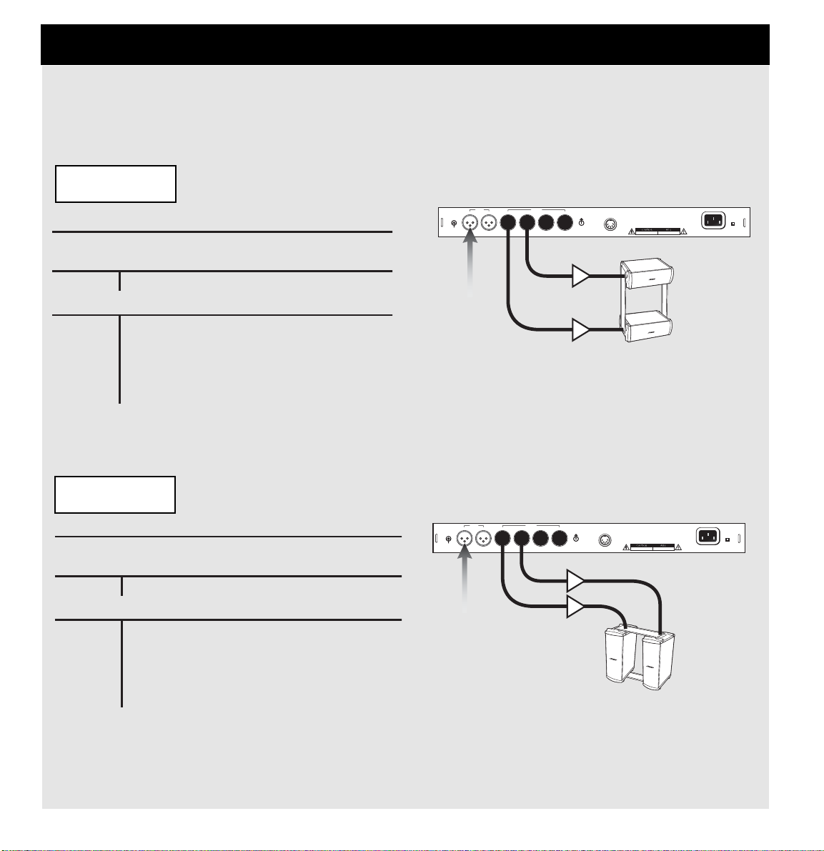
Stereo Preset Bank: Presets designed for Stereo operation.
Example 1: Stereo Full Range
PANARAY®System Digital Controller Display
Stereo
802III
CH1/MONO
From mixer
Left
INPUTS
Right
OUTPUTS
CH1
CH2
CH2 CH3
CH4
Bose Corporation, Framingham, MA 01701-9168
COM
RISK OF ELECTRICAL
DO NOT OPEN
Made in the U.S.A.
RISQUE DE CHOC ELECTRIQUE
NE PAS OUVRIR
POWER
100-240V~AC
50-60Hz
300W MAX
802®-III speaker
Right
(Full range)
802-III speaker
Left
(Full range)
Example 2: Stereo Mid-High with Stereo Bass
PANARAY System Digital Controller Display
Stereo
802III+MB4
INPUTS
CH2
CH1/MONO
OUTPUTS
CH1
CH2 CH3
CH4
Bose Corporation, Framingham, MA 01701-9168
COM
RISK OF ELECTRICAL
DO NOT OPEN
Made in the U.S.A.
RISQUE DE CHOC ELECTRIQUE
NE PAS OUVRIR
POWER
100-240V~AC
50-60Hz
300W MAX
From mixer
Right
Left
802-III
speaker
Right
(High freq)
802-III
speaker
Left
(High freq)
MB4 speaker
Right
(Low freq)
MB4 speaker
Left
(Low freq)
17
Page 18

5.1.1 PRESET Button – Stereo Bank
noitpircseDteserP
204
onoMrekaepS4BMhtiwoeretSrekaepSII-
stupnIrellortnoC
onoM/1hCreximmorftfeL
2hCreximmorfthgiR
gnituoRtuptuOtluafeDrellortnoC
1hC2hC3hC4hC
gnituoRrekaepsII-204
1HC
)qerfhgiH(
rekaepsII-204
2HC
)qerfhgiH(
rekaeps4BM
1HC
)qerfwoL(
rekaeps4BM
2HC
)qerfwoL(
retimiLffOffOffOffO
yaleDffOffOffOffO
Example 3: Stereo Mid-High with Mono Bass
Due to space limitations in the PANARAY®system digital controller, there are no Presets that default to
a Stereo Mid-High with Mono Bass configuration. To set up the controller for this operation, simply perform the following steps.
1. Select the desired Preset from the Stereo bank.
2. Press the UTILITY Button and use the Arrow DOWN button to navigate to Output Route 3 and
Output Route 4. Set both outputs to Mono/Low.
Now all of the bass content is set up to be summed to mono, but the mid-high devices will still be
stereo.
Note: Save all changes before loading a new Preset. Unsaved router changes will be lost if another
speaker EQ Preset is loaded. To save settings see section 11.0.
PANARAY System Digital Controller Display
Stereo
402II+MB4
INPUTS
CH2
CH1/MONO
OUTPUTS
CH1
CH2 CH3
CH4
Bose Corporation, Framingham, MA 01701-9168
COM
RISK OF ELECTRICAL
DO NOT OPEN
Made in the U.S.A.
RISQUE DE CHOC ELECTRIQUE
NE PAS OUVRIR
POWER
100-240V~AC
50-60Hz
300W MAX
18
402-II speaker
Left
(High freq)
MB4 speaker
Mono
(Low freq)
From mixer
402-II speaker
Right
Right
Left
(High freq)
Page 19

5.2 PRESET Button – Mono Bank
noitpircseDteserP
205
®
onoMrekaepSB205htiwonoMrekaepSA
stupnIrellortnoC
onoM/1hCreximmorfonoM
2hCtupnioN
gnituoRtuptuOtluafeDrellortnoC
1hC2hC3hC4hC
gnituoRrekaepsA205
onoM
)qerfhgiH(
rekaepsA205
onoM
)qerfhgiH(
rekaepsB205
onoM
)qerfwoL(
rekaepsB205
onoM
)qerfwoL(
retimiLffOffOffOffO
yaleDffOffOffOffO
noitpircseDteserP
204
egnaRlluFonoMrekaepSII-
stupnIrellortnoC
onoM/1hCreximmorfonoM
2hCtupnioN
gnituoRtuptuOtluafeDrellortnoC
1hC2hC3hC4hC
gnituoRrekaepsII-204
onoM
)egnarlluF(
rekaepsII-204
onoM
)egnarlluF(
rekaepsII-204
onoM
)egnarlluF(
rekaepsII-204
onoM
)egnarlluF(
retimiLffOffOffOffO
yaleDffOffOffOffO
Mono Preset Bank: Presets designed for Mono Operation.
Example 1: Mono Full Range
PANARAY®System Digital Controller Display
Mono
402II
CH1/MONO
INPUTS
CH2
OUTPUTS
CH1
CH2 CH3
CH4
Bose Corporation, Framingham, MA 01701-9168
COM
RISK OF ELECTRICAL
DO NOT OPEN
Made in the U.S.A.
RISQUE DE CHOC ELECTRIQUE
NE PAS OUVRIR
POWER
100-240V~AC
50-60Hz
300W MAX
Example 2: Mono Mid-High Device with Mono Bass
PANARAY System Digital Controller Display
Mono
502A+502B
Mono from
mixer
INPUTS
CH2
CH1/MONO
Mono from
mixer
OUTPUTS
CH1
CH2 CH3
CH4
402-II speaker
Mono
(Full range)
COM
502A speaker
Mono
(High freq)
®
®
Bose Corporation, Framingham, MA 01701-9168
Made in the U.S.A.
RISK OF ELECTRICAL
RISQUE DE CHOC ELECTRIQUE
DO NOT OPEN
NE PAS OUVRIR
POWER
100-240V~AC
50-60Hz
300W MAX
502B speaker
Mono
®
(Low freq)
19
Page 20
5.3 PRESET Button – Bass Array Bank
noitpircseDteserP
yarrAssaBedisdaorBx24BM:teserP
stupnIrellortnoC
1hCecruosonoM
gnituoRtuptuOtluafeDrellortnoC
1hC2hC3hC4hC
gnituoR)1(4BM
onoM
)2(4BM
onoM
A/NA/N
retimiLffOffOffOffO
yaleDffOffOffOffO
noitpircseDteserP
yarrAssaBerifdnEx24BM:teserP
stupnIrellortnoC
1hCecruosonoM
gnituoRtuptuOtluafeDrellortnoC
1hC2hC3hC4hC
gnituoR)1(4BM
onoM
)2(4BM
onoM
A/NA/N
retimiLffOffOffOffO
yaleDnOnOffOffO
Bose Corporation, Framingham, MA 01701-9168
Made in the U.S.A.
OUTPUTS
INPUTS
CH1
CH2 CH3
CH4
CH2
CH1/MONO
100-240V~AC
50-60Hz
300W MAX
RISQUE DE CHOC ELECTRIQUE
NE PAS OUVRIR
RISK OF ELECTRICAL
DO NOT OPEN
POWER
COM
Bose Corporation, Framingham, MA 01701-9168
Made in the U.S.A.
OUTPUTS
INPUTS
CH1
CH2 CH3
CH4
CH2
CH1/MONO
100-240V~AC
50-60Hz
300W MAX
RISQUE DE CHOC ELECTRIQUE
NE PAS OUVRIR
RISK OF ELECTRICAL
DO NOT OPEN
POWER
COM
Bass Array Presets:
Example 1: 2x Broadside Bass Array
PANARAY®System Digital Controller Display
Bass Array
MB4 2XBS180Hz
Example 2: 2x Endfire Bass Array
PANARAY System Digital Controller Display
Bass Array
MB4 2XEF180Hz
Mono from
mixer
MB4 (1)
MB4 (2)
20
Mono from
mixer
MB4 (1)
MB4 (2)
Page 21
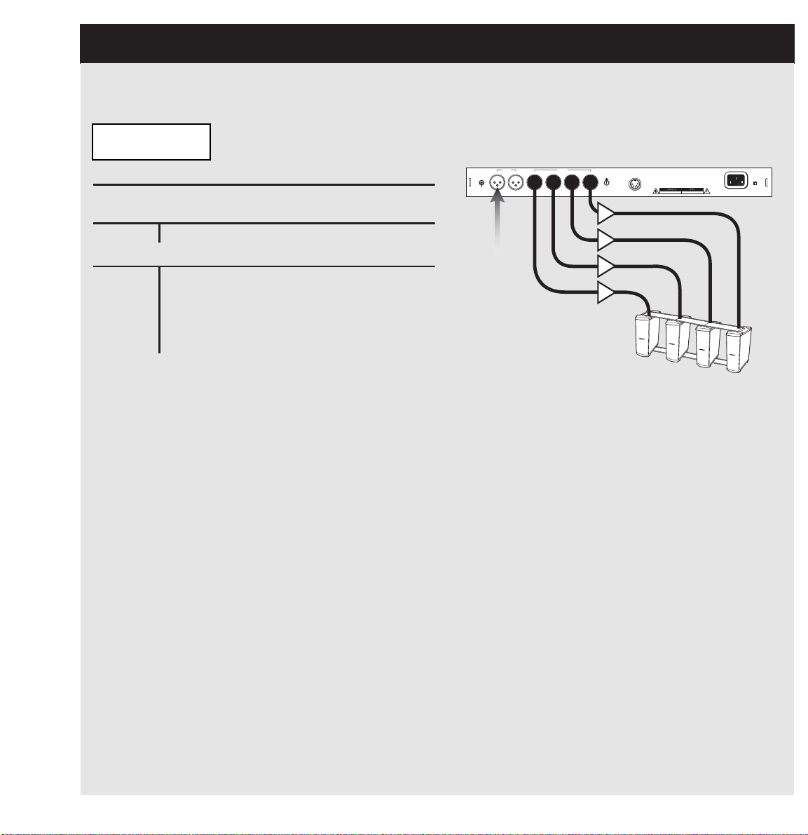
5.3 PRESET Button – Bass Array Bank
noitpircseDteserP
yarrAssaBerifdnEx44BM:teserP
stupnIrellortnoC
1hCecruosonoM
gnituoRtuptuOtluafeDrellortnoC
1hC2hC3hC4hC
gnituoR)1(4BM
onom
)2(4BM
onom
)3(4BM
onom
)4(4BM
onom
retimiLffOffOffOffO
yaleDnOnOnOnO
Bose Corporation, Framingham, MA 01701-9168
Made in the U.S.A.
OUTPUTS
INPUTS
CH1
CH2 CH3
CH4
CH2
CH1/MONO
100-240V~AC
50-60Hz
300W MAX
RISQUE DE CHOC ELECTRIQUE
NE PAS OUVRIR
RISK OF ELECTRICAL
DO NOT OPEN
POWER
COM
Example 2: 4x Endfire Bass Array
PANARAY®System Digital Controller Display
Bass Array
MB4 4XEF180Hz
Mono from
mixer
MB4 (1)
MB4 (2)
MB4 (3)
MB4 (4)
21
Page 22

5.4 PRESET Button – Dual Mono Operation
Loading presets from
Dual Mono mode:
Dual Mono: When the PANARAY®system digital
controller is used in Dual Mono mode, the
EQ/Crossover blocks process each input independently, allowing you to run two different speaker
EQs.
To access Dual Mono mode, press the PRESET
button. Then press the Arrow DOWN button until
you see the following display:
1: .402I
2: 402I
The period (.) next to the preset name indicates
that the Encoder can change the preset. To select
between 1 and 2, use the Arrow UP/Arrow Down
buttons.
CH1 Input
The top of the display shows the preset name that
will be processed by the CH1 input. This signal will
be routed to Outputs CH1 and CH2. If this is a fullrange preset, the same EQ will be applied to
Outputs CH1 and CH2. If this preset consists of a
mid-high device with a bass loudspeaker, the midhigh frequencies will be routed to Output CH1 and
the low frequencies will be routed to Output CH2.
Note: If you only have a connection plugged into
Input 1, the signal will only pass through Outputs 1
and 2.
If you only have a signal plugged into Input 2, the
signal will only pass through Outputs 3 and 4.
If you want to send the same audio information to
both of the PANARAY system digital controller’s
inputs, you can achieve this in two ways:
1. From your mixer set all of your pan controls to
center position (this will sum your information to
mono). Next plug the left and right outputs from
your mixer into CH1 and CH2 on the PANARAY
system digital controller.
2. From a mono source use a Y-cable to send the
same information into CH1 and Ch2 on the
PANARAY system digital controller.
CH2 Input
The bottom of the display shows the preset that is
processed by the CH2 input. This signal will be
routed to Outputs CH3 and CH4. If this is a fullrange preset, the same EQ will be applied to
Outputs CH3 and CH4. If this preset consists of a
mid-high device with a bass loudspeaker, the midhigh frequencies will be routed to Output CH3 and
the low frequencies will be routed to Output CH4.
22
Page 23

5.4 PRESET Button – Dual Mono Bank
steserPsteserP
steserP
steserPsteserP
208:1teserP
onoMrekaepSB205htiwrekaepSIII-
204:2teserP
onoMrekaepS4BMhtiwrekaepSII-
stupnIrellortnoCstupnIrellortnoC
stupnIrellortnoC
stupnIrellortnoCstupnIrellortnoC
1hCreximmorf1#ecruoS
2hCreximmorf2#ecruoS
gnituoRtuptuOtluafeDrellortnoCgnituoRtuptuOtluafeDrellortnoC
gnituoRtuptuOtluafeDrellortnoC
gnituoRtuptuOtluafeDrellortnoCgnituoRtuptuOtluafeDrellortnoC
1hC2hC3hC4hC
gnituoRrekaepsIII-208
1#ecruoS
)qerfhgiH(
rekaepsB205
1#ecruoS
)qerfwoL(
rekaepsII-204
2#ecruoS
)qerfhgiH(
rekaeps4BM
2#ecruoS
)qerfwoL(
retimiLffOffOffOffO
yaleDffOffOffOffO
noitpircseDteserP
205:1teserP
onoMrekaepSB205htiwrekaepSA
204:2teserP
II-
stupnIrellortnoC
1hC)elbac-Ymorf(ecruosonoM
2hC)elbac-Ymorf(ecruosonoM
gnituoRtuptuOtluafeDrellortnoC
1hC2hC3hC4hC
gnituoRA205
)qerfhgiH(
B205
)qerfwoL(
II204
)egnarlluF(
II204
)egnarlluF(
retimiLffOffOffOffO
yaleDffOffOffOffO
Bose Corporation, Framingham, MA 01701-9168
Made in the U.S.A.
OUTPUTS
INPUTS
CH1
CH2 CH3
CH4
CH2
CH1/MONO
100-240V~AC
50-60Hz
300W MAX
RISQUE DE CHOC ELECTRIQUE
NE PAS OUVRIR
RISK OF ELECTRICAL
DO NOT OPEN
POWER
COM
®
®
®
Dual Mono Presets: Independent selection of two single mono presets.
Example 1: Dual Mono
PANARAY®System Digital Controller Display
1: 802III+502B
2: 402II+MB4
From mixer
Source#1Source
INPUTS
CH2
CH1/MONO
#2
OUTPUTS
CH1
CH2 CH3
CH4
402-II speaker
Source #2
(High freq)
Bose Corporation, Framingham, MA 01701-9168
COM
Made in the U.S.A.
RISK OF ELECTRICAL
RISQUE DE CHOC ELECTRIQUE
DO NOT OPEN
NE PAS OUVRIR
802-III speaker
Source #1
(High freq)
POWER
MB4 speaker
Source #2
(Low freq)
502B speaker
Source #1
(Low freq)
100-240V~AC
50-60Hz
300W MAX
®
Zone 2
Zone 1
Example 2: Dual Mono
PANARAY System Digital Controller Display
1: 502A+502B
2: 402II
402-II speaker
(Full range)
402-II speaker
(High freq)
Mono from
mixer
502A speaker
(High freq)
Single
Zone
502B-speaker
(Full range)
23
Page 24
6.0 DELAY Button
retemaraPyaleDegnaR
1yaleDffO/nO
2yaleDffO/nO
3yaleDffO/nO
4yaleDffO/nO
1emityaleDsm00.002-sm00.0
2emityaleDsm00.002-sm00.0
3emityaleDsm00.002-sm00.0
4emityaleDsm00.002-sm00.0
S
Y
TANDB
INPUT METER TPM
L
-dB
40 24 18 12 6 0 O
R
Stereo Bank
802 Full Range
Pressing the DELAY button provides access to four
independent output delays. There is a single delay
line available on each of the controller’s four outputs. The delay function is always available regardless of the mode of operation.
Each delay provides up to 200ms of delay on each
of the four outputs (increments in 0.02ms intervals).
Use the Arrow UP and Arrow DOWN buttons to
navigate through the parameters, and use the
Encoder wheel to select parameter values.
The four output delays have the following
parameters:
Delay On/Off: Bypasses delay
Delay Time: Adjustable in 0.02ms increments
PRESET
UTILITY
LIMITER
DELAY
PANA RAY SYSTEM DIGITAL CONTROLLER
DELAY
24
Page 25
7.0 LIMITER Button
retemaraPretimiLegnaR
1miLffO/nO
2miLffO/nO
3miLffO/nO
4miLffO/nO
dlohserhT1miL1:fni-ffo
oitaR1miL1:fni-ffo
kcattA1miLsm001-sm0.1
esaeleR1miLs0.7-sm001
niaG1miLBd81-Bd001-
dlohserhT2miLBd0-Bb04-
oitaR2miL1:fni-ffo
kcattA2miLsm001-sm0.1
esaeleR2miLs0.7-sm001
niaG2miLBd81-Bd001-
dlohserhT3miLBd0-Bb04-
oitaR3miL1:fni-ffo
kcattA3miLsm001-sm0.1
esaeleR3miLs0.7-sm001
niaG3miLBd81-Bd001-
dlohserhT4miLBd0-Bb04-
oitaR4miL1:fni-ffo
kcattA4miLsm001-sm0.1
esaeleR4miLs0.7-sm001
niaG4miLBd81-Bd001-
S
Y
TANDB
INPUT METER TPM
L
-dB
40 24 18 12 6 0 O
R
Stereo Bank
802 Full Range
Pressing the LIMITER button provides access to
four independent output limiters that can protect
the loudspeakers from damage if an operator
overdrives the system. Use the Arrow UP and
Arrow DOWN buttons to navigate through the
parameters, and use the ENCODER wheel to
select parameter values.
The four output limiters each have the the
following parameters:
Limiter On/Off: Bypasses the limiter
Threshold: Sets the level at which the limiter
will activate. When the input signal exceeds the
threshold, the limiter will be activated. The lower
the threshold, the more sensitive the limiting will
be.
Ratio: The ratio of gain reduction.
For example: if the ratio is set to 4:1, it means
that for every 4dB the actual audio signal will
rise only 1dB over the threshold.
Attack: The time it takes the limiter to reach
gain reduction specified by the ratio parameter
when the signal is above the set threshold.
Release: Release is the time that the limiter
uses to release the gain reduction when the
signal exceeds the threshold.
Gain: Use the gain parameter to compensate
for unwanted gain reduction caused by heavy
limiting.
PRESET
UTILITY
LIMITER
LIMITER
DELAY
PANA RAY SYSTEM DIGITAL CONTROLLER
25
Page 26

8.0 UTILITY Button
S
Y
TANDB
INPUT METER TPM
L
-dB
40 24 18 12 6 0 O
R
Stereo Bank
802 Full Range
Pressing the UTILITY button provides access to
the Level, System and Routing parameters. Use
the Arrow UP/Arrow DOWN buttons to navigate
through the parameters, and use the Encoder
wheel to select parameter values.
Parameter Definitions:
Output Level
Controls the overall output level of outputs 1, 2, 3,
and 4.
Parameter Range: Off; -97dB to 0dB
Default Value: 0dB
Output Range
You can use this parameter to match the input level
of other equipment.
Parameter Range: 2dB, 8dB (consumer), 14dB, and
20dB (pro)
Default Value: 20dB
Allows you to adjust the maximum output level of
the PANARAY®system digital controller.
Input Sensitivity
Sets level in dBu to allow full-scale operation. A
digital product produces the best signal-to-noise
performance when operating at 0 dBFS (full scale).
For example: For a mixer with +4dBu outputs, the
Input Sensitivity should be set to +8dBu to account
for peaks in the programming material.
Parameter Range: 0dBu – 24dBu
Default Value: 20dBu
PRESET
LIMITER
DELAY
UTILITY
UTILITY
PANA RAY SYSTEM DIGITAL CONTROLLER
Input Trim CH1
Allows you to change the input level in 1dB steps
on CH1.
Parameter Range: -40dB to 0dB
Default Value: 20dB
Input Trim CH2
Allows you to change the input level in 1dB steps
on CH2.
Parameter Range: -40dB to 0dB
Default Value: 20dB
Output Route 1
Output Route 2
Output Route 3
Output Route 4
Note: See Section 9.0 on page 29 for details on
router functionality.
Delay Unit
Selectable between milliseconds, feet, and
meters.
Default Value: milliseconds
26
Page 27

8.0 UTILITY Button
Delay Master:
Selectable between PRESET and GLOBAL.
When set to PRESET, the delay values will be
reset each time a new preset is selected and will
match the delay values stored in the original preset.
When set to GLOBAL, the delay values remain
fixed atthe current settings even if a new preset is
loaded.
Default Value: PRESET
Limiter Master:
Selectable between PRESET or GLOBAL.
When set to PRESET, the limiter values will be
reset each time a new preset is selected and will
match the limiter values stored in the original preset.
When set to GLOBAL, the limiter values remain
fixed at the current settings even if a new preset
is loaded.
Default Value: PRESET
Input Configuration:
Selectable between Stereo, CH1+CH2 (sum),
or CH1 (mono).
Stereo: Optimizes input gain for stereo operation
CH1+CH2 (sum): Optimizes the input gain when
the controller is used to sum CH1 and CH2 to
MONO.
CH1 (mono): Optimizes the input gain when a
single input is used for MONO operation.
Note: When this option is selected CH2 input
does not work.
Default Value: Stereo
Lock Out:
Turns user lockout on and off.
Note: See section 8.1 for more details.
Default Value: Off
Custom Presets:
Provides access to stored presets. Selectable
between ON and OFF.
Default Value: Off
View Angle:
Adjusts display contrast. Selectable 0 – 7.
Default Value: 3
27
Page 28

8.1 UTILITY Button – User Lockout
User Lockout:
The User Lockout feature is available to prevent
others from tampering with the EQs and associated parameters that have been set.
To access the User Lockout feature, press the
UTILITY button, then press the Arrow UP/Arrow
DOWN button until you see the following display:
Lockout:
Off
Toggle the Encoder to select ON.
> Lockout <
On
When set to ON, the User Lockout feature locks
the current preset and prevents users from accessing the following buttons and their associated parameters:
PRESET
DELAY
LIMITER
UTILITY
To Disable User Lockout:
Press and hold the UTILITY button for five
seconds until you see the following display:
> Lockout <
> Unlocked <
User Lockout is now disabled.
Pressing any of these buttons or turning the
Encoder wheel will yield the following message on
the display:
> Lockout: <
> No Access <
28
Page 29

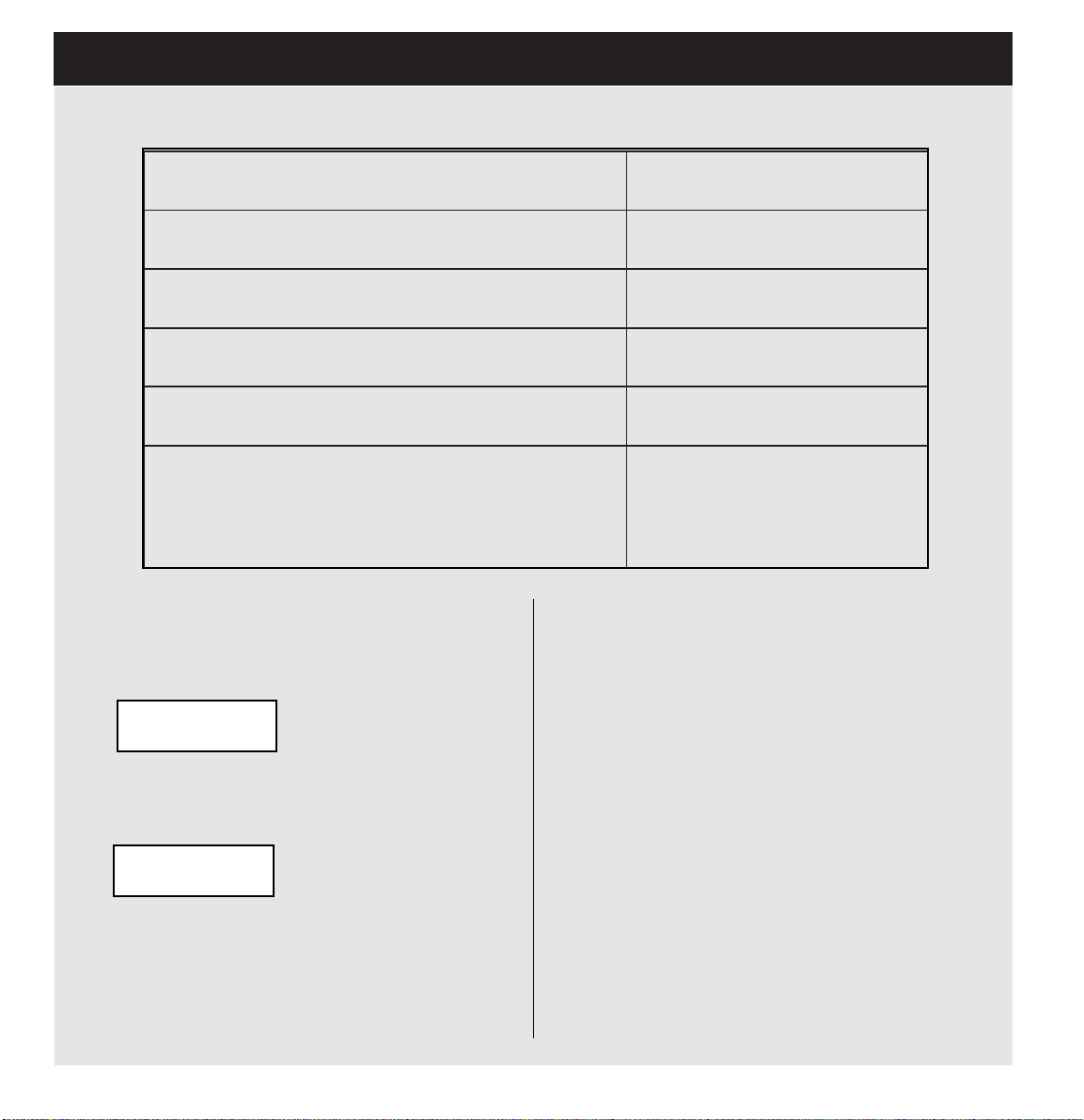
9.0 Router Functionality
The 2 x 4 router is updated every time a new
preset is loaded to reflect the stored output
configuration. The router can be manually edited
by the user to accommodate additional output
configurations.
To access the router, press the UTILITY button
and use the Arrow UP/Arrow DOWN buttons to
navigate through the Utility row. Use the Encoder
wheel to change router values.The following
routing parameters can be accessed under the
UTILITY button:
Output Route 1:
Selects audio information from the CH1 or CH2
inputs and sends it to Output CH1.
Default Value: The routing information is stored
with each preset.
Output Route 2:
Selects the type of audio information from the
CH1 or CH2 inputs and sends it to Output CH2.
Default Value: The routing information is stored
with each preset.
Output Route 3:
Selects the type of audio information from the
CH1 or CH2 inputs and sends it to Output CH3.
Default Value: The routing information is stored
with each preset.
Output Route 4:
Selects the type of audio information from the
CH1 or CH2 inputs and sends it to Output CH4.
Default Value: The routing information is stored
with each Preset.
Each of the four outputs can be set to the
following:
1. CH1/High Frequency: Selects the high
frequency information from the CH1
input.
2. CH2/High Frequency: Selects the high
frequency information from the CH2
input.
3. Mono/High Frequency: Selects the
high frequency information from the CH1
and CH2 inputs and sums them to
Mono.
4. CH1/Low Frequency: Selects the low-
frequency information from the CH1 input.
5. CH2/Low Frequency: Selects the low-
frequency information from the CH2 Input.
6. Mono/Low Frequency: Selects the low-
frequency information from the CH1 and
CH2 inputs and sums them to Mono.
7. CH1/Full Range: Selects the low-
frequency information from the CH1
input.
8. CH2/Full Range: Selects the low-
frequency information from the CH2
input.
9. Mono/Full Range: Selects information
from the CH1 and CH2 inputs and sums
them to Mono.
®
10. CH1/No EQ: Bypasses active Bose
EQ for
CH1 Program Material.
11. CH2/No EQ: Bypasses Active Bose EQ for
CH2 Program Material.
12. Mono/No EQ: Sums the CH1 and CH2 to
Mono and bypasses the Bose EQ presets.
29
Page 30

Router Functionality
PANARAY®System Digital Controller Output Configuration Table
Router Matrix
1etuoRtuptuO2etuoRtuptuO3etuoRtuptuO4etuoRtuptuO
hgiH/1HChgiH/1HChgiH/1HChgiH/1HC
hgiH/2HChgiH/2HChgiH/2HChgiH/2HC
hgiH/onoMhgiH/onoMhgiH/onoMhgiH/onoM
woL/1HCwoL/1HCwoL/1HCwoL/1HC
woL/2HCwoL/2HCwoL/2HCwoL/2HC
woL/onoMwoL/onoMwoL/onoMwoL/onoM
egnaRlluF/1HCegnaRlluF/1HCegnaRlluF/1HCegnaRlluF/1HC
egnaRlluF/2HCegnaRlluF/2HCegnaRlluF/2HCegnaRlluF/2HC
egnaRlluF/onoMegnaRlluF/onoMegnaRlluF/onoMegnaRlluF/onoM
30
QEoN/1HCQEoN/1HCQEoN/1HCQEoN/1HC
QEoN/2HCQEoN/2HCQEoN/2HCQEoN/2HC
QEoN/onoMQEoN/onoMQEoN/onoMQEoN/onoM
Page 31

10.0 Optimizing Signal-to-Noise
Optimizing Signal-to-Noise using
the PANARAY®System Digital
Controller with a Third-Party
Amplifier
In order to achieve the best signal-to-noise
performance with the PANARAY®system digital
controller, you must optimize the input sensitivity
and output range to match the equipment you are
interfacing with.
1. Before making any connections between the
PANARAY system digital controller and an
amplifier, make sure all of your electronics are
set to Off, and your amplifier level controls set
to Minimum.
2. Next, connect an audio source to the PANARAY
system digital controller inputs CH1 and CH2. If
you have a mono source, plug your connection
into CH1 and set the input configuration (located under the utility button) to CH1 (mono).
3. Connect the PANARAY system digital controller outputs to your amplifier inputs.
4. Turn on your audio source. Then turn on your
PANARAY system digital controller.
so you should run the PANARAY system digital
controller as close to 0dBFS as possible.
For example: If you have a mixer with +4dBU
outputs, the PANARAY controller input sensitivity
should be set to +8dBu. This will allow you to
reach 0dBFS while at the same time providing
some additional headroom to account for peaks in
program material. Set the parameter based on the
amount of headroom needed.
To access the PANARAY system digital controller
input sensitivity, press the UTILITY button. Then
press the Arrow DOWN button until you see the following display:
Input Sense
20dBu
Adjust this parameter with the Encoder wheel to
match your audio source’s maximum output.
Input Sense
8dBu
Next, send a signal from your audio source to the
PANARAY system digital controller and view the
front panel input meters to ensure your signal is at
approximately 0dbFS (full scale). Adjust the input
sensitivity parameter accordingly.
5. Select a Speaker EQ on the Panaray
controller by pressing the PRESET button and
use the Encoder wheel to select the desired
speaker EQ.
6. Set the PANARAY system digital controller’s
input sensitivity. In general you should set this
parameter to match the output range of the
equipment you connect to the controller. A
digital product has the best signal-to-noise performance when operating at 0dBFS (full scale),
Note: The input signal may occasionally light the
red Overload LED. This is normal.
7. After you have properly calibrated your
PANARAY controller’s input sensitivity, you
must adjust your controller’s output range to
match your amplifier’s input sensitivity. Since
this will vary with each manufacturer, please
consult your amplifier user guide.
31
Page 32
10.0 Optimizing Signal-to-Noise
retemaraPegnaRtuptuO ytivitisneStupnIreifilpmA
uBd2 V577.0nahtsselgnihtynarofesU
uBd8 V579.0otV577.0
uBd41 V9.3otV579.0
uBd02 V57.7otV9.3
:etoN ruoyhctamyltcaxetahtsgnittesoneraerehtfI
tahtgnittestsehgihehtkcip,ytivitisnestupnis'reifilpma
ehtesudnaytivitisnestupnireifilpmaruoytseraensi
ehtkcabelacsotlortnocLEVELTUPTUOs'rellortnoc
.tuptuollarevo
Use the table below to match the PANARAY®system digital controller’s Output Range to your amplifier.
Set the PANARAY system digital controller output range. First, press the UTILITY button.
Then press the Arrow DOWN button until you
see the following display:
Output Range
20dB (Pro)
Adjust this parameter with the Encoder wheel
to match your amplifier’s input sensitivity.
Output Range
14dB (Consumer)
This setting will provide the optimum input level
for your amplifier.
32
8. Select a speaker EQ preset on the PANARAY
system digital controller by pressing the
PRESET button and using the Encoder wheel
to select the desired speaker EQ preset.
9. Turn your amplifier On, and turn up each level
control until you reach the desired SPL.
These settings will automatically be retained.
Page 33

11.0 Custom Preset Mode
®
The PANARAY
allows users to edit and store the delay, limiting and
routing settings. Up to 20 custom presets can be
stored using this feature.
After making the desired changes to a preset,
follow the steps below to store a new preset.
1. Press and hold the DELAY and LIMITER
buttons at the same time (for approximately 5
seconds) until you see the following display:
Store: Select no
1>EMPTY PRESET
Use the Encoder wheel to select the location
where the preset will be stored (up to 20 loca
tions can be used).
2. Once you have selected your location, press
the Arrow DOWN button to name your preset.
You will see the following display:
Store: Edit name
1 402I
Use the Arrow UP/Arrow DOWN buttons to
align the cursor under the desired letter or
number you want to change, then move the
Encoder wheel through the list of characters.
Press the Arrow UP button to move to the
next character, and press the Arrow DOWN
button to move back. To CANCEL the store
process, press the PRESET button.
3. Once you have named your preset, press
and holdD the DELAY and LIMITER buttons
until you see the following display:
> Preset <
> Stored <
controller’s Custom Preset feature
After you store a program, you will be immediately transferred to the custom preset mode. The
stored preset will be displayed. Note that the
bank designation will be based on the preset that
you edited.
For example: If the preset came from the Mono
bank, it will be designated as Mono Custom. If a
preset originates from the Stereo bank then it will
be designated as Stereo Custom. And if a preset
originates from the Bass Array bank, it will be
designated as Bass Array Custom.
Mono Custom
402I - TEST
In this mode, the user only has access to the
custom presets. Select presets in the same
manner as in the standard operating mode. The
Encoder wheel selects presets and the Arrow
UP/Arrow DOWN buttons select the desired
bank.
To Turn Off Custom Presets:
To turn off custom presets and return to standard
operation press the UTILITY button and use the
Arrow UP/Arrow DOWN button to find the
Custom Presets parameter and set it to Off.
You will immediately be transferred to standard
operating mode.
To Activate Custom Presets:
To return to custom preset mode, go back to the
UTILITY row and turn the Custom Presets parameter to On. You will immediately be transferred
to custom preset mode.To create additional custom presets, repeat the procedure above.
Note: You cannot store a Dual Mono preset, but
can create one by storing two custom mono presets, which you have access to in custom preset
mode. Follow standard operation instructions for
loading Dual Mono presets.
33
Page 34

12.0 Bass Array Presets
The following presets are available in the
PANARAY®system digital controller for Bass
Array Applications:
MB4 2xBS280Hz – The MB4 2x Broadside Bass
Array preset provides 360 degree horizontal coverage with a 10 to 15dB suppression in energy
going up and down from 80 – 200Hz. The
crossover is set at 280Hz and is recommended
for use with the LT Series.
MB4 2xBS180Hz – The MB4 2x Broadside Bass
Array preset provides 360 degree horizontal coverage with a 10 to 15dB suppression in energy
going up and down from 80 – 200Hz. The
crossover is set at 180Hz and is recommended
for use with MA12, MB4 and 02 Series speakers.
MB4 2xEF280Hz – The MB4 2x Endfire Bass
Array preset provides 180 degree conical dispersion @ 160Hz. The crossover is set at 280Hz
and is recommended for use with MA12, MB4
and LT Series speakers.
MB4 2xEF180Hz – The MB4 2x Endfire Bass
Array preset provides 180 degree conical dispersion @ 160Hz. The crossover is set at 180Hz
and is recommended for use with MA12, MB4
and 02 Series speakers.
Loading and Setting Up Bass Arrays
Using Presets
1. Press the PRESET button on the front panel
of the PANARAY system digital controller.
2. Press the Arrow DOWN button until you see
the following display:
Bass Array
MB4 2xBS280Hz
3. Turn the Encoder wheel to the right to
select the desired bass array configuration.
Bass Array
MB4 4xEF280Hz
4. Once you have selected your bass array
preset, the program is automatically loaded
and ready to go.
MB4 4xEF280Hz – The MB4 4x Endfire Bass
Array preset provides 120 degree conical dispersion @ 160Hz. The crossover is set at 280Hz
and is recommended for use with MA12, MB4
and LT Series speakers.
MB4 4xEF180Hz – The MB4 4x Endfire Bass
Array preset provides 120 degree conical dispersion @ 160Hz. The crossover is set at 180Hz
and is recommended for use with MA12, MB4
and 02 Series speakers.
34
Page 35
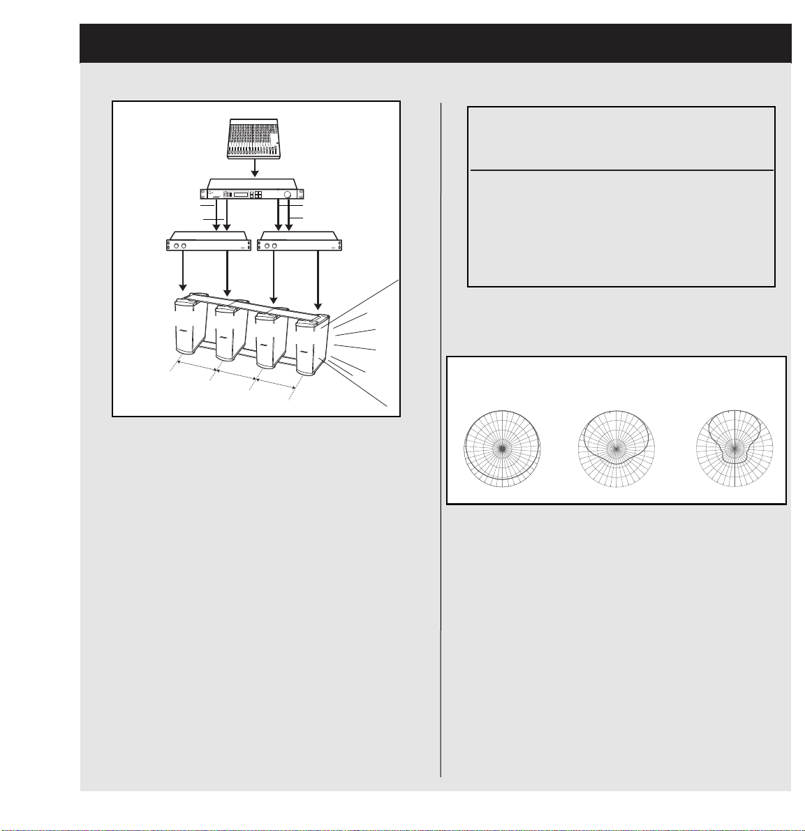
12.1 Bass Array Setup and Connections
)zH081dnazH082(yarrassaberifdnex44BM
YARANAP
tuptuorellortnoclatigidmetsys
1HC)1(4BM
2HC)2(4BM
3HC)3(4BM
4HC)4(4BM
R
0
63H
0
270
MB4 4x Endfire Bass Array
Out 1
Out 2
MB4 1
29"
(73.6 cm)
POWE
MB4 2
Stereo Bank
0O
802 Full Range
29"
(73.6 cm)
PRESET
LIMIT
DELAY
UTILITY
PANARAY DIGITAL SYSTEM CONTROLLER
MB4 3
29"
(73.6 cm)
Out 3
Out 4
MB4 4
Bose®Components:
1PANARAY®system digital controller
2 Bose 1800-VI power amplifiers
2 4x endfire bass array brackets (top and bottom)
4 MB4 modular bass loudspeakers
Spacing:
In order to effectively create the MB4 4x endfire
bass array, each unit must be spaced 29" (73.6 cm)
on center from each other. This is shown in the illustration above. IF THE UNITS ARE NOT SPACED
PROPERLY THE BASS ARRAY WILL NOT WORK.
MB4 4x Endfire Horizontal Octave-Band Polar Data
270
40Hz
0
180
z
270
90
180
90
125Hz
180
This array fires from the end of the fourth MB4
speaker to provide the dispersion shown above.
90
Note: All EQ and delay settings are already set in
the PANARAY system digital controller. In order for
the bass array to work, you must connect the MB4
units to the appropriate outputs on the controller
and apply the proper spacing. The output assignments are listed to the right.
35
Page 36
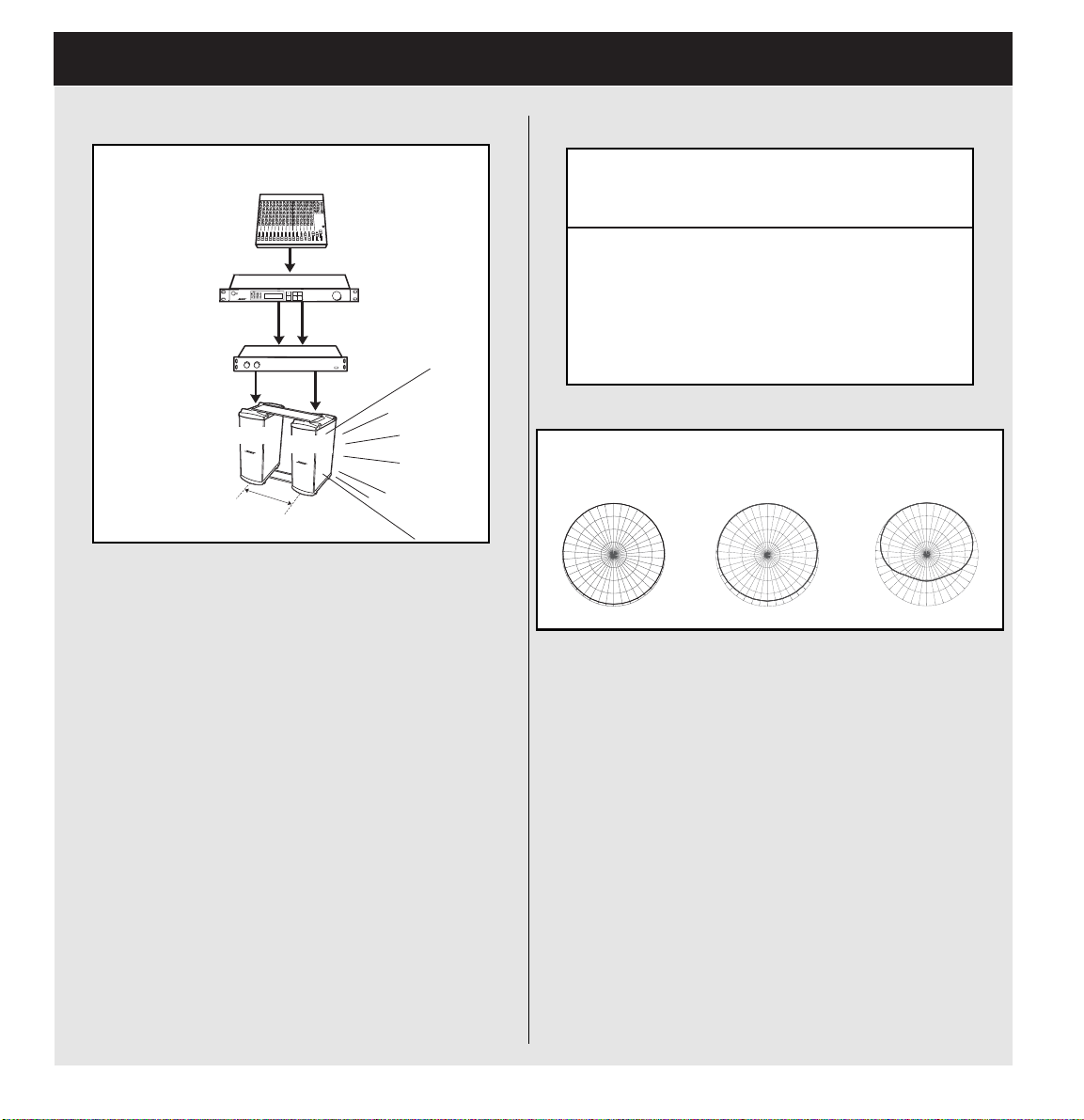
12.1 Bass Array Setup and Connections
MB4 2x Endfire Bass Array
)zH081dnazH082(yarrassaberifdnex44BM
PRESET
LIMIT
Stereo Bank
802 Full Range
DELAY
UTILITY
PANARAY DIGITAL SYSTEM CONTROLLER
Out 1
MB4 1
23"
(58.4 cm)
Out 2
MB4 2
Bose®Components:
1PANARAY®system digital controller
1 Bose 1800-VI power amplifier
2 2x endfire bass array brackets (top and bottom)
2 MB4 modular bass loudspeakers
Spacing:
In order to effectively create the MB4 2x endfire
bass array, each unit must be spaced 23" (58.4 cm)
on center from each other). This is shown in the
illustration above. IF THE UNITS ARE NOT
SPACED PROPERLY THE BASS ARRAY WILL
NOT WORK.
YARANAP
tuptuorellortnoclatigidmetsys
1HC)1(4BM
2HC)2(4BM
3HC)3(4BM
4HC)4(4BM
MB4 2x Endfire Horizontal Octave-Band Polar Data
270
40Hz
0
180
63Hz
0
270
90
180
90
125Hz
0
270
180
This array fires from the end of the second MB4
speaker to provide the dispersion shown above.
90
Note: All EQ and delay settings are already set in
the PANARAY system digital controller. In order for
the bass array to work, you must connect the MB4
units to the appropriate outputs on the controller
and apply the proper spacing. The output assignments are listed to the right.
36
Page 37

12.1 Bass Array Setup and Connections
R
0
90
180
270
Horiz.
Vert.
MB4 2x Broadside Bass Array
)zH081dnazH082(yarrassabedisdaorbx24BM
PRESET
LIMIT
Stereo Bank
802 Full Range
DELAY
UTILITY
Out 1
MB4 1
MB4 2
PANARAY DIGITAL SYSTEM CONTROLLE
Out 2
45"
(114.3 cm)
Bose®Components:
®
1PANARAY
system digital controller
1 Bose 1800-VI power amplifier
2 2x broadside bass array brackets (top and bottom)
2 MB4 modular bass loudspeakers
Spacing:
In order to effectively create the MB4 2x endfire bass
array, each unit must be spaced 45" (114.3 cm) on
center from each other. This is shown in the illustration above. IF THE UNITS ARE NOT SPACED
PROPERLY THE BASS ARRAY WILL NOT WORK.
YARANAP
tuptuorellortnoclatigidmetsys
1HC)1(4BM
2HC)2(4BM
3HCdesutoN
4HCdesutoN
MB4 2x Broadside Horizontal Octave-Band Polar Data
40Hz
270
63Hz
0
180
90
Horiz.
Vert.
125Hz
0
270
180
This array fires from the sides of both MB4
speakers to provide the dispersion shown above.
90
Horiz.
Vert.
Note: All EQ and delay settings are already set in the
PANARAY system digital controller. In order for the
bass array to work, you must connect the MB4 units
to the appropriate outputs on the controller and apply
the proper spacing. The output assignments are listed to the right.
37
Page 38

13.0 Bose®Speaker EQ Preset List
The following is a list of 180 presets that are available in the PANARAY®system digital controller. The presets are separated into three separate banks: Mono, Stereo and Bass Array. Included in this list is the name
of each preset as it appears on the PANARAY controller LCD as well as a description of the preset and the
default settings for each of the four outputs.
yalpsiDDCL noitpircseDteserP noitarugifnoCtluafeDtuptuO
steserPonoMnoitpircseDteserP1tuptuO2tuptuO3tuptuO4tuptuO
emaNteserPonoMnoitpircseDteserP
teserPoeretSnoitpircseDteserP1tuptuO2tuptuO3tuptuO4tuptuO
emaNteserPoeretSnoitpircseDteserP
yarrAssaBnoitpircseDteserP1tuptuO2tuptuO3tuptuO4tuptuO
emaNteserPyarrAssaBnoitpircseDteserP
teserP
tluafeD
teserP
tluafeD
teserP
tluafeD
teserP
tluafeD
teserP
tluafeD
teserP
tluafeD
teserP
tluafeD
teserP
tluafeD
teserP
tluafeD
teserP
tluafeD
teserP
tluafeD
teserP
tluafeD
38
Page 39
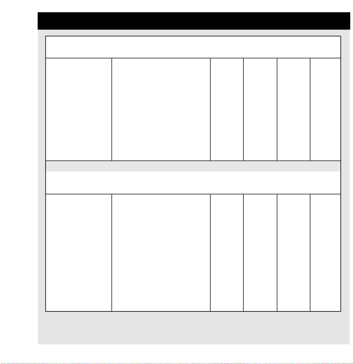
13.1 Bose®Speaker EQ Preset List – Mono Bank
YARANAP
204
rekaepsduol
steserPonoM
IseireS
IseireS204
rekaepsduol
snoitpircseDteserP1tuptuO2tuptuO3tuptuO4tuptuO
I204QEegnaRlluFrekaepsduolIseireS204onoMI204
B205+I204htiwdepma-ibrekaepsduolIseireS204
205
rekaepsduolB
4BM+I204htiwdepma-ibrekaepsduolIseireS204
4BM
SCWA+I204htiwdepma-ibrekaepsduolIseireS204
SCWA
dna3stuptuootdengissasignitimiL:etoN
SCWAehtfonoitcetorprof4
FHI204@depma-ibrekaepsduolIseireS204
zH061
204YARANAP
rekaepsduol
steserPonoM
IIseireS
IIseireS204
rekaepsduol
snoitpircseDteserP1tuptuO2tuptuO3tuptuO4tuptuO
II204QEegnaRlluFrekaepsduolIIseireS204onoMII204
B205+II204htiwdepma-ibrekaepsduolIIseireS204
rekaepsduolB205
XEB205+II204htiwdepma-ibrekaepsduolIIseireS204
rekaepsduolXEB205
egnaRlluF
onoMI204
hgiH
onoMI204
hgiH
onoMI204
hgiH
onoMI204
hgiH
egnaRlluF
onoMI204
hgiH
onoMI204
hgiH
onoMI204
hgiH
onoMI204
hgiH
onoMII204
onoMI204
egnaRlluF
onoMII204
hgiH
onoMII204
hgiH
egnaRlluF
onoMII204
hgiH
onoMII204
hgiH
onoMI204
egnaRlluF
onoMB205
woL
onoM4BM
woL
SCWA
woLonoM
onoMI204
hgiH
onoMII204
egnaRlluF
onoMB205
woL
XEB205
woLonoM
onoMI204
egnaRlluF
onoMB205
woL
onoM4BM
woL
SCWA
woLonoM
onoMI204
hgiH
onoMII204
egnaRlluF
onoMB205
woL
XEB205
woLonoM
4BM+II204htiwdepma-ibrekaepsduolIIseireS204
SCWA+II204htiwdepma-ibrekaepsduolIIseireS204
FHII204@depma-ibrekaepsduolIIseireS204
4BM
hgiH
onoMII204
onoMII204
SCWA
hgiH
onoMII204
hgiH
onoMII204
hgiH
onoM4BM
woL
SCWA
woLonoM
onoM4BM
woL
SCWA
woLonoM
dna3stuptuootdengissasignitimiL:etoN
.SCWAehtfonoitcetorprof4
zH081
hgiH
onoMII204
onoMII204
hgiH
onoMII204
hgiH
onoMII204
hgiH
39
Page 40
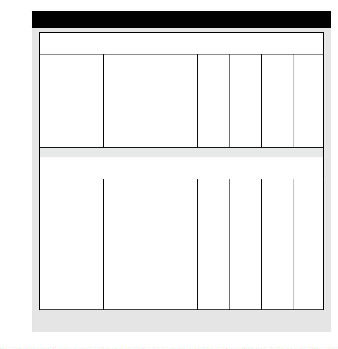
13.1 Bose®Speaker EQ Preset List – Mono Bank
YARANAP
205A
rekaepsduol
steserPonoM
A205
rekaepsduol
snoitpircseDteserP1tuptuO2tuptuO3tuptuO4tuptuO
A205QEegnaRlluFrekaepsduolA205onoMA205
B205+A205B205htiwdepma-ibrekaepsduolA205onoMA205
4BM+A2054BMhtiwdepma-ibrekaepsduolA205onoMA205
SCWA+A205SCWAhtiwdepma-ibrekaepsduolA205
FHA205zH061@depma--ibrekaepsduolA205onoMA205
208YARANAP
rekaepsduol
steserPonoM
II208QEegnaRlluFrekaepsduolIIseireS208onoMII208
B205+II208htiwdepma-ibrekaepsduolIIseireS208
4BM+II208htiwdepma-ibrekaepsduolIIseireS208
IIseireS
4BM
IIseireS208
rekaepsduol
snoitpircseDteserP1tuptuO2tuptuO3tuptuO4tuptuO
rekaepsduolB205
3stuptuootdengissasignitimiL:etoN
SCWAehtfonoitcetorprof4dna
egnaRlluF
hgiH
hgiH
onoMA205
hgiH
hgiH
egnaRlluF
onoMII208
hgiH
onoMII208
hgiH
onoMA205
egnaRlluF
onoMA205
hgiH
onoMA205
hgiH
onoMA205
hgiH
onoMA205
hgiH
onoMII208
egnaRlluF
onoMII208
hgiH
onoMII208
hgiH
onoMA205
egnaRlluF
onoMB205
woL
onoM4BM
woL
SCWA
woLonoM
onoMA205
hgiH
onoMII208
egnaRlluF
onoMB205
woL
onoM4BM
woL
onoMA205
egnaRlluF
onoMB205
woL
onoM4BM
woL
SCWA
woLonoM
onoMA205
hgiH
onoMII208
egnaRlluF
onoMB205
woL
onoM4BM
woL
40
SCWA+II208htiwdepma-ibrekaepsduolIIseireS208
SCWA
3stuptuootdengissasignitimiL:etoN
SCWAehtfonoitcetorprof4dna
FHII208@depma-ibrekaepsduolIIseireS208
zH211
KTSII208QErekaepsduolIIseireS208dekcatSlluFII208
B205+KTSII208-ibsrekaepsduolIIseireS208dekcatS
rekaepsduolB205htiwdepma
onoMII208
hgiH
onoMII208
hgiH
egnaR
onoMII208
hgiH
onoMII208
hgiH
onoMII208
hgiH
lluFII208
egnaR
onoMII208
hgiH
SCWA
woLonoM
hgiHII208hgiHII208
lluFII208
egnaR
onoMB205
woL
SCWA
woLonoM
lluFII208
egnaR
onoMB205
woL
Page 41
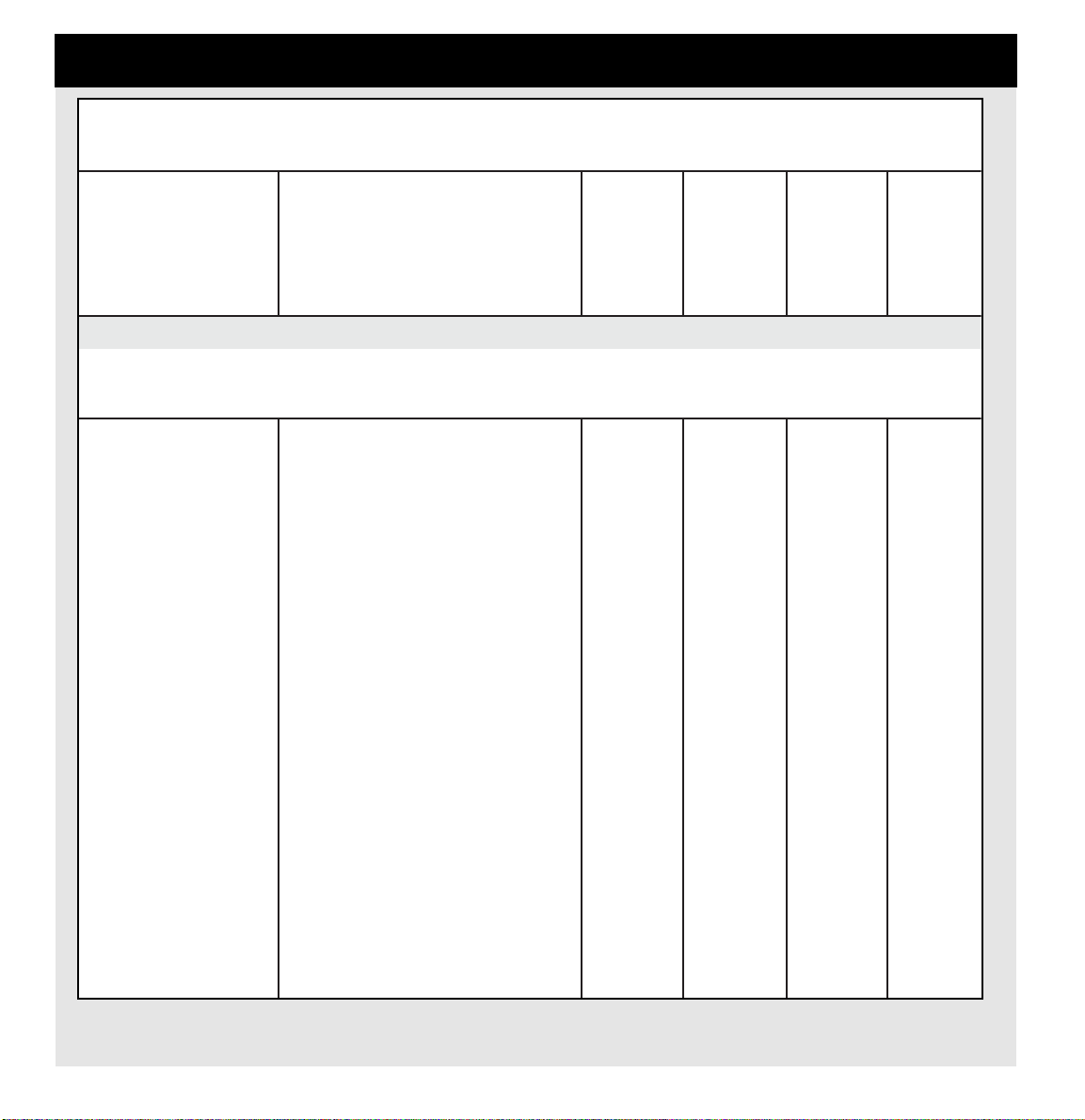
Bose®Speaker EQ Preset List – Mono Bank
YARANAP
208
rekaepsduol
steserPonoM
IIseireS
IIseireS208
rekaepsduol
snoitpircseDteserP1tuptuO2tuptuO3tuptuO4tuptuO
SCWA+KTSII208srekaepsduolIIseireS208dekcatS
FHKTSII208srekaepsduolIIseireS208dekcatS
IIIseireS208YARANAP
rekaepsduol
steserPonoM
III208QEegnaRlluFrekaepsduolIIIseireS208onoMIII208
B205+III208htiwdepma-ibrekaepsduolIIIseireS208
XEB205+III208htiwdepma-ibrekaepsduolIIIseireS208
4BM+III208htiwdepma-ibrekaepsduolIIIseireS208
4BM
SCWA+III208htiwdepma-ibrekaepsduolIIIseireS208
SCWA
SCWAhtiwdepmaib
3stuptuootdengissasignitimiL:etoN
SCWAehtfonoitcetorprof4dna
zH211@depmaib
IIIseireS208
rekaepsduol
snoitpircseDteserP
rekaepsduolB205
rekaepsduolXEB205
3stuptuootdengissasignitimiL:etoN
SCWAehtfonoitcetorprof4dna
onoMII208
hgiH
onoMII208
hgiH
1tuptuO2tuptuO3tuptuO4tuptuO
egnaRlluF
onoMIII208
hgiH
onoMIII208
hgiH
onoMIII208
hgiH
onoMIII208
hgiH
onoMII208
hgiH
onoMII208
hgiH
onoMIII208
egnaRlluF
onoMIII208
hgiH
hgiH
hgiH
hgiH
woL
onoMIII208
onoMIII208
woL
onoMIII208
SCWA
woLonoM
onoMII208
hgiH
onoMIII208
egnaRlluF
onoMB205
XEB205
woLonoM
onoM4BM
SCWA
woLonoM
SCWA
woLonoM
onoMII208
hgiH
onoMIII208
egnaRlluF
onoMB205
woL
XEB205
woLonoM
onoM4BM
woL
SCWA
woLonoM
FHIII208@depma-ibrekaepsduolIIIseireS208
zH521
TSIII208QErekaepsduolIIIseireS208dekcatSonoMIII208
B205+TSIII208-ibsrekaepsduolIIIseireS208dekcatS
rekaepsduolB205htiwdepma
X205+TSIII208-ibsrekaepsduolIIIseireS208dekcatS
rekaepsduolXEB205htiwdepma
4BM+KTSIII208-ibsrekaepsduolIIIseireS208dekcatS
4BMhtiwdepma
onoMIII208
hgiH
egnaRlluF
onoMIII208
hgiH
onoMIII208
hgiH
onoMIII208
hgiH
onoMIII208
hgiH
onoMIII208
egnaRlluF
onoMIII208
hgiH
onoMIII208
hgiH
onoMIII208
hgiH
onoMIII208
hgiH
onoMIII208
egnaRlluF
onoMB205
woL
XEB205
woLonoM
onoM4BM
woL
onoMIII208
hgiH
onoMIII208
egnaRlluF
onoMB205
woL
XEB205
woLonoM
onoM4BM
woL
41
Page 42

Bose®Speaker EQ Preset List – Mono Bank
YARANAP
208
rekaepsduol
steserPonoM
IIIseireS
IIIseireS208
rekaepsduol
snoitpircseDteserP1tuptuO2tuptuO3tuptuO4tuptuO
SCWA+KTSIII208-ibrekaepsduolIIIseireS208dekcatS
PHKTSIII208-ibrekaepsduolIIIseireS208dekcatS
YARANAP21AM
rekaepsduol
steserPonoM
LLAW21AM,egnaRlluFrekaepsduol21AM
EERF21AM,dleiFeerF,egnaRlluFrekaepsduol21AM
B205+21AM205htiwdepma-ibrekaepsduol21AM
4BM+21AM4BMhtiwdepma-ibrekaepsduol21AMonoM21AM
FH21AMzH061@depma-ibrekaepsduol21AMonoM21AM
LLAWKTS21AM,egnaRlluFrekaepsduol21AMdekcatS
21AM
evruCQE
SCWAhtiwdepma
zH521@depma
rekaepsduol
snoitpircseDteserP1tuptuO2tuptuO3tuptuO4tuptuO
evruCQE,tnuoMllaW
rekaepsduol
evruCQE,tnuoMllaW
3stuptuootdengissasignitimiL:etoN
SCWAehtfonoitcetorprof4dna
B
III208
hgiH/onoM
III208
hgiH/onoM
onoM21AM
egnaRlluF
onoM21AM
egnaRlluF
onoM21AM
hgiH
hgiH
hgiH
onoM21AM
egnaRlluF
III208
hgiH/onoM
III208
hgiH/onoM
onoM21AM
egnaRlluF
onoM21AM
egnaRlluF
onoM21AM
hgiH
onoM21AM
hgiH
onoM21AM
hgiH
onoM21AM
egnaRlluF
III208
woL/onoM
III208
hgiH/onoM
onoM21AM
egnaRlluF
onoM21AM
egnaRlluF
onoMB205
woL
onoM4BM
woL
onoM21AM
hgiH
onoM21AM
egnaRlluF
III208
woL/onoM
III208
hgiH/onoM
onoM21AM
egnaRlluF
onoM21AM
egnaRlluF
onoMB205
woL
onoM4BM
woL
onoM21AM
hgiH
onoM21AM
egnaRlluF
42
EERFKTS21AM,egnaRlluFrekaepsduol21AMdekcatS
B205+KTS21AMhtiwdepma-ibrekaepsduol21AMdekcatS
4BM+KTS21AMhtiwdepma-ibrekaepsduol21AMdekcatS
FHKTS21AM@depma-ibrekaepsduol21AMdekcatS
evruCQE,dleiFeerF
rekaepsduolB205
4BM
zH061
onoM21AM
egnaRlluF
onoM21AM
hgiH
onoM21AM
hgiH
onoM21AM
hgiH
onoM21AM
egnaRlluF
onoM21AM
hgiH
hgiH
hgiH
woL
onoM21AM
woL
onoM21AM
onoM21AM
egnaRlluF
onoMB205
woL
onoM4BM
woL
onoM21AM
hgiH
onoM21AM
egnaRlluF
onoMB205
onoM4BM
onoM21AM
hgiH
Page 43

Bose®Speaker EQ Preset List – Mono Bank
YARANAP
4BM
rekaepsduol
steserPonoM
PLzH0014BMssaPwoLzH001rekaepsduol4BM4BM4BM4BM4BM
PLzH0614BMssaPwoLzH061rekaepsduol4BM4BM4BM4BM4BM
PLzH0024BMssaPwoLzH002rekaepsduol4BM4BM4BM4BM4BM
PLzH0824BMssaPwoLzH082rekaepsduol4BM4BM4BM4BM4BM
205YARANAP
B
rekaepsduol
steserPonoM
4BM
rekaepsduol
snoitpircseDteserP1tuptuO2tuptuO3tuptuO4tuptuO
B205
rekaepsduol
snoitpircseDteserP1tuptuO2tuptuO3tuptuO4tuptuO
B205ssaPwoLonoMrekaepsduolB205
zH061@
205YARANAP
XEB
rekaepsduol
steserPonoM
XEB205
teserPrekaepsduol
snoitpircseD1tuptuO2tuptuO3tuptuO4tuptuO
XEB205ssaPwoLonoMrekaepsduolXEB205
zH002@
steserPonoMSCWAsnoitpircseDteserPSCWA1tuptuO2tuptuO3tuptuO4tuptuO
SCWAgnitimilhtiwssaPwoLonoMSCWA
stuptuoruofllaotdengissa
2023TLYARANAP
steserPonoM
rekaepsduol2023TL
snoitpircseDteserP1tuptuO2tuptuO3tuptuO4tuptuO
2023TLQEegnaRlluFrekaepsduol2023TL2023TL
RETSULC2023TLQEretsulCrekaepsduol2023TL2023TL
B205B205B205B205
XEB205XEB205XEB205XEB205
SCWASCWASCWASCWA
onoM
egnaRlluF
onoM
egnaRlluF
2023TL
2023TL
onoM
egnaRlluF
onoM
egnaRlluF
2023TL
onoM
egnaRlluF
2023TL
onoM
egnaRlluF
2023TL
onoM
egnaRlluF
2023TL
onoM
egnaRlluF
4BM+2023TL4BMhtiwdepma-ibrekaepsduol2023TL2023TL
XEB205+2023TLhtiwdepma-ibrekaepsduol2023TL
rekaepsduolXEB205
hgiHonoM
2023TL
hgiHonoM
hgiHonoM
2023TL
hgiHonoM
2023TL
4BM
woLonoM
XEB205
woLonoM
4BM
woLonoM
XEB205
woLonoM
43
Page 44

Bose®Speaker EQ Preset List – Mono Bank
YARANAP
2044TL
rekaepsduol
steserPonoM
2044TL
rekaepsduol
snoitpircseDteserP1tuptuO2tuptuO3tuptuO4tuptuO
2044TLQEegnaRlluFrekaepsduol2044TL2044TL
RETSULC2044TLQEretsulC2044TL2044TL
4BM+2044TL4BMhtiwdepma-ibrekaepsduol2044TL2044TL
XEB205+2044TLhtiwdepma-ibrekaepsduol2044TL
2079TLYARANAP
rekaepsduol
steserPonoM
205
rekaepsduolXEB
2079TL
rekaepsduol
snoitpircseDteserP1tuptuO2tuptuO3tuptuO4tuptuO
2079TLQEegnaRlluFrekaepsduol2079TL2079TL
RETSULC2079TLQEretsulC2079TL2079TL
lluFonoM
egnaR
lluFonoM
egnaR
2044TL
2044TL
lluFonoM
egnaR
lluFonoM
egnaR
2044TL
hgiHonoM
2044TL
hgiHonoM
hgiHonoM
2044TL
hgiHonoM
2079TL
lluFonoM
egnaR
lluFonoM
egnaR
2079TL
lluFonoM
egnaR
lluFonoM
egnaR
2044TL
lluFonoM
egnaR
2044TL
lluFonoM
egnaR
4BM
woLonoM
XEB205
woLonoM
2079TL
lluFonoM
egnaR
2079TL
lluFonoM
egnaR
2044TL
lluFonoM
egnaR
2044TL
lluFonoM
egnaR
4BM
woLonoM
XEB205
woLonoM
2079TL
lluFonoM
egnaR
2079TL
lluFonoM
egnaR
4BM+2079TL4BMhtiwdepma-ibrekaepsduol2079TL2079TL
XEB205+2079TLhtiwdepma-ibrekaepsduol2079TL
rekaepsduolXEB205
ecapSeerF
8ledoM
rekaepsduol
steserPonoM
8ledoM
rekaepsduol
snoitpircseDteserP1tuptuO2tuptuO3tuptuO4tuptuO
8MQEegnaRlluFrekaepsduol8ledoMonoM8M
4BM+8M4BMhtiwdepma-ibrekaepsduol8ledoMonoM8M
3SF+8Mhtiwdepma-ibrekaepsduol8ledoM
ecapSeerF
rekaepsduol3
B1SF+8Mhtiwdepma-ibrekaepsduol8ledoM
rekaepsduolB1ecapSeerF
44
hgiHonoM
2079TL
hgiHonoM
hgiHonoM
2079TL
hgiHonoM
onoM8M
2079TL
egnaRlluF
egnaRlluF
onoM8M
hgiH
onoM8M
hgiH
onoM8M
hgiH
hgiH
onoM8M
hgiH
onoM8M
hgiH
4BM
woLonoM
XEB205
woLonoM
onoM8M
egnaRlluF
onoM4BM
woL
onoM3SF
woL
woL
4BM
woLonoM
XEB205
woLonoM
onoM8M
egnaRlluF
onoM4BM
woL
onoM3SF
woL
onoMB1SF
onoMB1SF
woL
Page 45

Bose®Speaker EQ Preset List – Mono Bank
o
o
o
ecapSeerF
rekaepsduol
23MQEegnaRlluFrekaepsduol23ledoMonoM23M
4BM+23M4BMhtiwdepma-ibrekaepsduol23ledoMonoM23M
3SF+23M3SFhtiwdepma-ibrekaepsduol23ledoMonoM23M
B1SF+23MB1SFhtiwdepma-ibrekaepsduol23ledoMonoM23M
XEB205+23Mhtiwdepma-ibrekaepsduol23ledoM
23ledoM
steserPonoM
23ledoM
rekaepsduol
snoitpircseDteserP1tuptuO2tuptuO3tuptuO4tuptuO
205
rekaepsduolXEB
egnaRlluF
hgiH
hgiH
hgiH
onoM23M
hgiH
onoM23M
egnaRlluF
onoM23M
hgiH
onoM23M
hgiH
onoM23M
hgiH
onoM23M
hgiH
onoM23M
egnaRlluF
onoM4BM
woL
onoM3SF
woL
woLB1SFwoLB1SF
XEB205
woLonoM
onoM23M
egnaRlluF
onoM4BM
woL
onoM3SF
woL
XEB205
woLonoM
B1ledoMecapSeerF
rekaepsduol
steserPonoM
PLzH001B1SFzH001rekaepsduolB1ledoMecapSeerF
ssaPwoL
ECAFRUSB1SFecafruSrekaepsduolB1ledoMecapSeerF
QEtnuoM
HSULFB1SFhsulFrekaepsduolB1ledoMecapSeerF
QEtnuoM
ssaB3ecapSeerF
steserPonoM
PLzH0013SFssaPwoLzH001ssaB3ecapSeerF3SF3SF3SF3SF
PLzH0513SFssaPwoLzH051ssaB3ecapSeerF3SF3SF3SF3SF
063ecapSeerF
steserPonoM
DRAH063SFQEdrahdnuorgnirekaepsduol063SFonoM063SF
TFOS063SFQEtfosdnuorgnirekaepsduol063SFonoM063SF
KCED063SFQEkcedrekaepsduol063SFonoM063SF
B1ledoMecapSeerF
rekaepsduol
snoitpircseDteserP1tuptuO2tuptuO3tuptuO4tuptuO
B1SFB1SFB1SFB1SF
B1SFB1SFB1SFB1SF
B1SFB1SFB1SFB1SF
ssaB3ecapSeerF
snoitpircseDteserP1tuptuO2tuptuO3tuptuO4tuptuO
snoitpircseDteserP1tuptuO2tuptuO3tuptuO4tuptuO
rekaepsduol063ecapSeerF
egnaRlluF
egnaRlluF
egnaRlluF
063SF
lluFonoM
egnaR
063SF
lluFonoM
egnaR
063SF
lluFonoM
egnaR
onoM063SF
egnaRlluF
onoM063SF
egnaRlluF
onoM063SF
egnaRlluF
noM063SF
egnaRlluF
noM063SF
egnaRlluF
noM063SF
egnaRlluF
45
Page 46

13.2 Bose®Speaker EQ Preset List – Stereo Bank
YARANAP
204
rekaepsduol
steserPoeretS
IseireS
IseireS204
rekaepsduol
snoitpircseDteserP1tuptuO2tuptuO3tuptuO4tuptuO
I204QEegnaRlluFrekaepduolIseireS204I204
B205+I204htiwdepma-ibrekaepsduolIseireS204
205
rekaepsduolB
4BM+I204htiwdepma-ibrekaepsduolIseireS204
4BM
SCWA+I204htiwdepma-ibrekaepsduolIseireS204
SCWA
3stuptuootdengissasignitimiL:etoN
SCWAehtfonoitcetorprof4dna
FHI204@depma-ibrekaepsduolIseireS204
zH061
204yaranaP
rekaepsduol
steserPoeretS
IIseireS
IIseireS204
rekaepsduol
snoitpircseDteserP1tuptuO2tuptuO3tuptuO4tuptuO
II204QEegnaRlluFrekaepduolIIseireS204II204
B205+II204htiwdepma-ibrekaepsduolIIseireS204
rekaepsduolB205
lluF/1HC
egnaR
I204
hgiH/1HC
I204
hgiH/1HC
I204
hgiH/1HC
I204
hgiH/1HC
lluF/2HC
egnaR
I204
hgiH/2HC
I204
hgiH/2HC
I204
hgiH/2HC
I204
hgiH/2HC
II204
I204
lluF/1HC
egnaR
II204
hgiH/1HC
lluF/2HC
egnaR
II204
hgiH/2HC
I204
lluF/1HC
egnaR
B205
woL/1HC
4BM
woL/1HC
SCWA
woL/1HC
I204
hgiH/1HC
II204
lluF/1HC
egnaR
B205
woL/1HC
I204
lluF/2HC
egnaR
B205
woL/2HC
4BM
woL/2HC
SCWA
woL/2HC
i204
hgiH/2HC
II204
lluF/2HC
egnaR
B205
woL/2HC
46
XEB205+II204htiwdepma-ibrekaepsduolIIseireS204
4BM+II204htiwdepma-ibrekaepsduolIIseireS204
SCWA+II204htiwdepma-ibrekaepsduolIIseireS204
FHII204@depma-ibrekaepsduolIIseireS204
205
rekaepsduolXEB
II204
hgiH/1HC
II204
4BM
hgiH/1HC
II204
SCWA
hgiH/1HC
II204
hgiH/2HC
II204
hgiH/2HC
II204
hgiH/2HC
XEB205
woL/1HC
4BM
woL/1HC
SCWA
woL/1HC
XEB205
woL/2HC
4BM
woL/2HC
SCWA
woL/2HC
3stuptuootdengissasignitimiL:etoN
SCWAehtfonoitcetorprof4dna
zH081
hgiH/1HC
II204
II204
hgiH/2HC
II204
hgiH/1HC
II204
hgiH/2HC
Page 47

Bose®Speaker EQ Preset List – Stereo Bank
YARANAP
205A
rekaepsduol
steserPoeretS
A205
rekaepsduol
snoitpircseDteserP1tuptuO2tuptuO3tuptuO4tuptuO
A205QEegnaRlluFrekaepsduolA205A205
B205+A205B205htiwdepma-ibrekaepsduolA205A205
4BM+A2054BMhtiwdepma-ibrekaepsduolA205A205
SCWA+A205SCWAhtiwdepma-ibrekaepsduolA205
FHA205zH061@depma-ibrekaepsduolA205A205
208YARANAP
rekaepsduol
steserPoeretS
II208QEegnaRlluFrekaepsduolIIseireS208II208
B205+II208htiwdepma-ibrekaepsduolIIseireS208
4BM+II208htiwdepma-ibrekaepsduolIIseireS208
IIseireS
4BM
IIseireS208
rekaepsduol
snoitpircseDteserP1tuptuO2tuptuO3tuptuO4tuptuO
rekaepsduolB205
3stuptuootdengissasignitimiL:etoN
SCWAehtfonoitcetorprof4dna
lluF/1HC
egnaR
hgiH/1HC
hgiH/1HC
A205
hgiH/1HC
hgiH/1HC
lluF/1HC
egnaR
II208
hgiH/1HC
II208
hgiH/1HC
A205
lluF/2HC
egnaR
A205
hgiH/2HC
A205
hgiH/2HC
A205
hgiH/2HC
A205
hgiH/2HC
II208
lluF/2HC
egnaR
II208
hgiH/2HC
II208
hgiH/2HC
A205
lluF/1HC
egnaR
B205
woL/1HC
4BM
woL/1HC
SCWA
woL/1HC
A205
hgiH/1HC
II208
lluF/1HC
egnaR
B205
woL/1HC
4BM
woL/1HC
A205
lluF/2HC
egnaR
B205
woL/2HC
4BM
woL/2HC
SCWA
woL/2HC
A205
hgiH/2HC
II208
lluF/2HC
egnaR
B205
woL/2HC
4BM
woL/2HC
SCWA+II208htiwdepma-ibrekaepsduolIIseireS208
SCWA
3stuptuootdengissasignitimiL:etoN
SCWAehtfonoitcetorprof4dna
FHII208@depma-ibrekaepsduolIIseireS208
zH211
KTSII208QErekaepsduolIIseireS208dekcatSII208
B205+KTSII208-ibsrekaepsduolIIseireS208dekcatS
rekaepduolB205htiwdepma
4BM+KTSII208-ibsrekaepsduolIIseireS208dekcatS
4BMhtiwdepma
II208
hgiH/1HC
II208
hgiH/1HC
lluF/1HC
egnaR
II208
hgiH/1HC
II208
hgiH/1HC
II208
hgiH/2HC
II208
hgiH/2HC
II208
lluF/2HC
egnaR
II208
hgiH/2HC
II208
hgiH/2HC
SCWA
woL/1HC
II208
hgiH/1HC
II208
lluF/1HC
egnaR
B205
woL/1HC
4BM
woL/1HC
SCWA
woL/2HC
II208
hgiH/2HC
II208
lluF/2HC
egnaR
B205
woL/2HC
4BM
woL/2HC
47
Page 48

13.2 Bose®Speaker EQ Preset List – Stereo Bank
YARANAP
208
rekaepsduol
steserPoeretS
IIseireS
IIseireS208
rekaepsduol
snoitpircseDteserP1tuptuO2tuptuO3tuptuO4tuptuO
SCWA+KTSII208-ibsrekaepsduolIIseireS208dekcatS
SCWAhtiwdepma
3stuptuootdengissasignitimiL:etoN
SCWAehtfonoitcetorprof4dna
FHKTSII208-ibsrekaepsduolIIseireS208dekcatS
zH211@depma
208YARANAP
rekaepsduol
steserPoeretS
IIIseireS
IIIseireS208
rekaepsduol
snoitpircseDteserP1tuptuO2tuptuO3tuptuO4tuptuO
III208QEegnaRlluFrekaepsduolIIIseireS208III208
B205+III208htiwdepma-ibrekaepsduolIIIseireS208
205
rekaepsduolB
XEB205+III208htiwdepma-ibrekaepsduolIIIseireS208
rekaepsduolXEB205
4BM+III208htiwdepma-ibrekaepsduolIIIseireS208
4BM
SCWA+III208htiwdepma-ibrekaepsduolIIIseireS208
SCWA
3stuptuootdengissasignitimiL:etoN
SCWAehtfonoitcetorprof4dna
II208
hgiH/1HC
II208
hgiH/1HC
lluF/1HC
egnaR
III208
hgiH/1HC
III208
hgiH/1HC
III208
hgiH/1HC
III208
hgiH/1HC
II208
hgiH/2HC
II208
hgiH/2HC
III208
lluF/2HC
egnaR
III208
hgiH/2HC
III208
hgiH/2HC
III208
hgiH/2HC
III208
hgiH/2HC
SCWA
woL/1HC
II208
hgiH/1HC
III208
lluF/1HC
egnaR
B205
woL/1HC
XEB205
woL/1HC
4BM
woL/1HC
SCWA
woL/1HC
SCWA
woL/2HC
II208
hgiH/2HC
III208
lluF/2HC
egnaR
B205
woL/2HC
XEB205
woL/2hC
4BM
woL/2HC
SCWA
woL/2HC
48
FHIII208@depma-ibrekaepsduolIIIseireS208
zH521
TSIII208QErekaepsduolIIIseireS208dekcatSIII208
B205+TSIII208-ibsrekaepsduolIIIseireS208dekcatS
B205htiwdepma
X205+TSIII208-ibsrekaepsduolIIIseireS208dekcatS
XEB205htiwdepma
4BM+KTSIII208-ibsrekaepsduolIIIseireS208dekcatS
4BMhtiwdepma
III208
hgiH/1HC
lluF/1HC
egnaR
III208
hgiH/1HC
III208
hgiH/1HC
III208
hgiH/1HC
III208
hgiH/2HC
III208
lluF/2HC
egnaR
III208
hgiH/2HC
III208
hgiH/2HC
III208
hgiH/2HC
III208
hgiH/1HC
III208
lluF/1HC
egnaR
B205
woL/1HC
XEB205
woL/1HC
4BM
woL/1HC
III208
hgiH/2HC
III208
lluF/2HC
egnaR
B205
woL/2HC
XEB205
woL/2HC
4BM
woL/2HC
Page 49

Bose®Speaker EQ Preset List – Stereo Bank
YARANAP
208
rekaepsduol
steserPoeretS
IIIseireS
IIIseireS208
rekaepsduol
snoitpircseDteserP1tuptuO2tuptuO3tuptuO4tuptuO
SCWA+KTSIII208-ibrekaepsduolIIIseireS208dekcatS
PHKTSIII208-ibrekaepsduolIIIseireS208dekcatS
YARANAP21AM
rekaepsduol
steserPoeretS
LLAW21AM,egnaRlluFrekaepsduol21AM
EERF21AM,dleiFeerF,egnaRlluFrekaepsduol21AM
B205+21AM205htiwdepma-ibrekaepsduol21AM
4BM+21AM4BMhtiwdepma-ibrekaepsduol21AM21AM
FH21AMzH061@depma-ibrekaepsduol21AM21AM
21AM
evruCQE
SCWAhtiwdepma
zH521@depma
rekaepsduol
snoitpircseDteserP1tuptuO2tuptuO3tuptuO4tuptuO
evruCQE,tnuoMllaW
rekaepsduol
3stuptuootdengissasignitimiL:etoN
SCWAehtfonoitcetorprof4dna
B
III208
hgiH/1HC
III208
hgiH/1HC
21AM
lluF/1HC
egnaR
21AM
lluF/1HC
egnaR
21AM
hgiH/1HC
hgiH/1HC
hgiH/1HC
III208
hgiH/2HC
III208
hgiH/2HC
21AM
lluF/2HC
egnaR
21AM
lluF/2HC
egnaR
21AM
hgiH/2HC
21AM
hgiH/2HC
21AM
hgiH/2HC
SCWA
woL/1HC
III208
hgiH/1HC
21AM
lluF/1HC
egnaR
21AM
lluF/1HC
egnaR
B205
woL/1HC
4BM
woL/1HC
onoM21AM
hgiH
SCWA
woL/2HC
III208
hgiH/2HC
21AM
lluF/2HC
egnaR
21AM
lluF/2HC
egnaR
B205
woL/2HC
4BM
woL/2HC
onoM21AM
hgiH
LLAWKTS21AM,egnaRlluFrekaepsduol21AMdekcatS
EERFKTS21AM,egnaRlluFrekaepsduol21AMdekcatS
B205+KTS21AMB205htiwdepma-ibrekaepsduoldekcatS
4BM+KTS21AMhtiwdepma-ibrekaepsduol21AMdekcatS
FHKTS21AM@depma-ibrekaepsduol21AMdekcatS
evruCQE,tnuoMllaW
evruCQE,dleiFeerF
rekaepsduol
4BM
zH061
21AM
lluF/1HC
egnaR
21AM
lluF/1HC
egnaR
21AM
hgiH/1HC
21AM
hgiH/1HC
21AM
hgiH/1HC
21AM
lluF/2HC
egnaR
21AM
lluF/2HC
egnaR
21AM
hgiH/2HC
21AM
hgiH/2HC
21AM
hgiH/2HC
21AM
lluF/1HC
egnaR
21AM
lluF/1HC
egnaR
B205
woL/1HC
4BM
woL/1HC
21AM
hgiH/1HC
21AM
lluF/2HC
egnaR
21AM
lluF/2HC
egnaR
B205
woL/2HC
4BM
woL/2HC
21AM
hgiH/2HC
49
Page 50
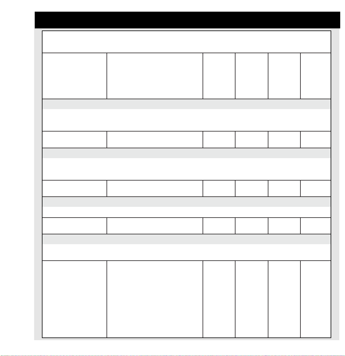
Bose®Speaker EQ Preset List – Stereo Bank
®
YARANAP
4BM
rekaepsduol
steserPoeretS
PLzH0014BMssaPwoLzH001rekaepsduol4BM1HC/4BM2HC/4BM1HC/4BM2HC/4BM
PLzH0614BMssaPwoLzH061rekaepsduol4BM1HC/4BM2HC/4BM1HC/4BM2HC/4BM
PLzH0024BMssaPwoLzH002rekaepsduol4BM1HC/4BM2HC/4BM1HC/4BM2HC/4BM
PLzH0824BMssaPwoLzH082rekaepsduol4BM1HC/4BM2HC/4BM1HC/4BM2HC/4BM
®
205YARANAP
B
rekaepsduol
steserPonoM
4BM
rekaepsduol
snoitpircseDteserP1tuptuO2tuptuO3tuptuO4tuptuO
B205
rekaepsduol
snoitpircseDteserP1tuptuO2tuptuO3tuptuO4tuptuO
B205ssaPwoLonoMrekaepsduolB205
zH061@
®
205YARANAP
XEB
rekaepsduol
steserPoeretS
XEB205
teserPrekaepsduol
snoitpircseD1tuptuO2tuptuO3tuptuO4tuptuO
XEB205ssaPwoLonoMrekaepsduolXEB205
zH002@
steserPoeretSSCWAsnoitpircseDteserPSCWA1tuptuO2tuptuO3tuptuO4tuptuO
SCWAgnitimilhtiwssaPwoLonoMSCWA
stuptuoruofllaotdengissa
®
2023TLYARANAP
steserPoeretS
rekaepsduol2023TL
snoitpircseDteserP1tuptuO2tuptuO3tuptuO4tuptuO
2023TLQEegnaRlluFrekaepsduol2023TL2023TL
RETSULC2023TLQEretsulCrekaepsduol2023TL2023TL
1HC/B2052HC/B2051HC/B2052HC/B205
/XEB205
1HC
/XEB205
2HC
1HC/SCWA2HC/SCWA1HC/SCWA2HC/SCWA
2023TL
1HC
egnaRlluF
2HC
egnaRlluF
2023TL
1HC
egnaRlluF
2HC
egnaRlluF
/XEB205
1HC
2023TL
1HC
egnaRlluF
2023TL
1HC
egnaRlluF
/XEB205
2HC
2023TL
2HC
egnaRlluF
2023TL
2HC
egnaRlluF
50
4BM+2023TL4BMhtiwdepma-ibrekaepsduol2023TL2023TL
XEB205+2023TLhtiwdepma-ibrekaepsduol2023TL
rekaepsduolXEB205
hgiH/1HC
2023TL
hgiH/1HC
hgiH/2HC
2023TL
hgiH/2HC
2023TL
4BM
woL/1HC
XEB205
woL/1HC
4BM
woL/2HC
XEB205
woL/2HC
Page 51

Bose®Speaker EQ Preset List – Stereo Bank
YARANAP
2044TL
rekaepsduol
steserPonoM
2044TL
rekaepsduol
snoitpircseDteserP1tuptuO2tuptuO3tuptuO4tuptuO
2044TLQEegnaRlluFrekaepsduol2044TL2044TL
RETSULC2044TLQEretsulC2044TL2044TL
4BM+2044TL4BMhtiwdepma-ibrekaepsduol2044TL2044TL
XEB205+2044TLhtiwdepma-ibrekaepsduol2044TL
2079TLYARANAP
rekaepsduol
steserPonoM
205
rekaepsduolXEB
2079TL
rekaepsduol
snoitpircseDteserP1tuptuO2tuptuO3tuptuO4tuptuO
2079TLQEegnaRlluFrekaepsduol2079TL2079TL
RETSULC2079TLQEretsulC2079TL2079TL
lluFonoM
egnaR
lluFonoM
egnaR
2044TL
2044TL
lluFonoM
egnaR
lluFonoM
egnaR
2044TL
hgiHonoM
2044TL
hgiHonoM
hgiHonoM
2044TL
hgiHonoM
2079TL
lluFonoM
egnaR
lluFonoM
egnaR
2079TL
lluFonoM
egnaR
lluFonoM
egnaR
2044TL
lluFonoM
egnaR
2044TL
lluFonoM
egnaR
4BM
woLonoM
XEB205
woLonoM
2079TL
lluFonoM
egnaR
2079TL
lluFonoM
egnaR
2044TL
lluFonoM
egnaR
2044TL
lluFonoM
egnaR
4BM
woLonoM
XEB205
woLonoM
2079TL
lluFonoM
egnaR
2079TL
lluFonoM
egnaR
4BM+2079TL4BMhtiwdepma-ibrekaepsduol2079TL2079TL
XEB205+2079TLhtiwdepma-ibrekaepsduol2079TL
rekaepsduolXEB205
ecapSeerF
8ledoM
rekaepsduol
steserPonoM
8ledoM
rekaepsduol
snoitpircseDteserP1tuptuO2tuptuO3tuptuO4tuptuO
8MQEegnaRlluFrekaepsduol8ledoMonoM8M
4BM+8M4BMhtiwdepma-ibrekaepsduol8ledoMonoM8M
3SF+8Mhtiwdepma-ibrekaepsduol8ledoM
ecapSeerF
rekaepsduol3
B1SF+8Mhtiwdepma-ibrekaepsduol8ledoM
rekaepsduolB1ecapSeerF
hgiHonoM
2079TL
hgiHonoM
hgiHonoM
2079TL
hgiHonoM
onoM8M
2079TL
egnaRlluF
egnaRlluF
onoM8M
hgiH
onoM8M
hgiH
onoM8M
hgiH
hgiH
onoM8M
hgiH
onoM8M
hgiH
4BM
woLonoM
XEB205
woLonoM
onoM8M
egnaRlluF
onoM4BM
woL
onoM3SF
woL
woL
4BM
woLonoM
XEB205
woLonoM
onoM8M
egnaRlluF
onoM4BM
woL
onoM3SF
woL
onoMB1SF
onoMB1SF
woL
51
Page 52
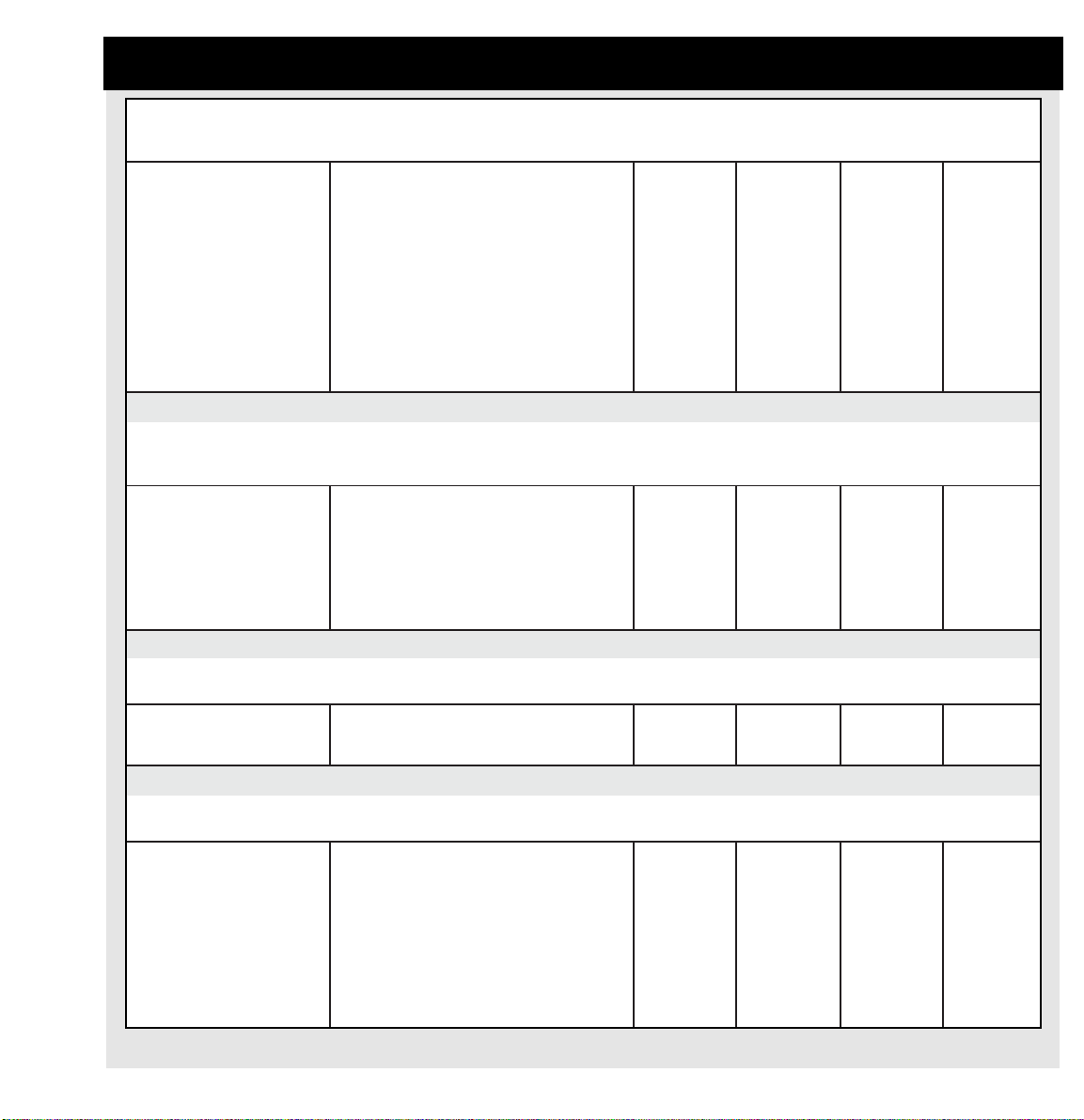
Bose®Speaker EQ Preset List – Stereo Bank
ecapSeerF
rekaepsduol
23MQEegnaRlluFrekaepsduol23ledoMonoM23M
4BM+23M4BMhtiwdepma-ibrekaepsduol23ledoMonoM23M
3SF+23M3SFhtiwdepma-ibrekaepsduol23ledoMonoM23M
B1SF+23MB1SFhtiwdepma-ibrekaepsduol23ledoMonoM23M
XEB205+23Mhtiwdepma-ibrekaepsduol23ledoM
23ledoM
steserPonoM
23ledoM
rekaepsduol
snoitpircseDteserP1tuptuO2tuptuO3tuptuO4tuptuO
205
rekaepsduolXEB
egnaRlluF
hgiH
hgiH
hgiH
onoM23M
hgiH
onoM23M
egnaRlluF
onoM23M
hgiH
onoM23M
hgiH
onoM23M
hgiH
onoM23M
hgiH
onoM23M
egnaRlluF
onoM4BM
woL
onoM3SF
woL
woLB1SFwoLB1SF
XEB205
woLonoM
onoM23M
egnaRlluF
onoM4BM
woL
onoM3SF
woL
XEB205
woLonoM
B1ledoMecapSeerF
rekaepsduol
steserPonoM
PLzH001B1SFzH001rekaepsduolB1ledoMecapSeerF
ssaPwoL
ECAFRUSB1SFecafruSrekaepsduolB1ledoMecapSeerF
QEtnuoM
HSULFB1SFhsulFrekaepsduolB1ledoMecapSeerF
QEtnuoM
ssaB3ecapSeerF
steserPonoM
PLzH0013SFssaPwoLzH001ssaB3ecapSeerF3SF3SF3SF3SF
PLzH0513SFssaPwoLzH051ssaB3ecapSeerF3SF3SF3SF3SF
063ecapSeerF
steserPonoM
DRAH063SFQEdrahdnuorgnirekaepsduol063SFonoM063SF
TFOS063SFQEtfosdnuorgnirekaepsduol063SFonoM063SF
KCED063SFQEkcedrekaepsduol063SFonoM063SF
B1ledoMecapSeerF
rekaepsduol
snoitpircseDteserP1tuptuO2tuptuO3tuptuO4tuptuO
B1SFB1SFB1SFB1SF
B1SFB1SFB1SFB1SF
B1SFB1SFB1SFB1SF
ssaB3ecapSeerF
snoitpircseDteserP1tuptuO2tuptuO3tuptuO4tuptuO
snoitpircseDteserP1tuptuO2tuptuO3tuptuO4tuptuO
rekaepsduol063ecapSeerF
egnaRlluF
egnaRlluF
egnaRlluF
063SF
lluFonoM
egnaR
063SF
lluFonoM
egnaR
063SF
lluFonoM
egnaR
egnaRlluF
egnaRlluF
egnaRlluF
onoM063SF
onoM063SF
onoM063SF
onoM063SF
egnaRlluF
onoM063SF
egnaRlluF
onoM063SF
egnaRlluF
52
Page 53

Bose®Speaker EQ Preset List – Bass Array Bank
YARANAP
4BM
steserPyarrAssaBsnoitpircseDteserPyarrAssaB4BM1tuptuO2tuptuO3tuptuO4tuptuO
zH081SBx24BMteserpyarrassabedisdaorbx24BMehT
zH082SBx24BMteserpyarrassabedisdaorbx24BMehT
zH081FEx24BMsedivorpteserpyarrassaberifdnex24BMehT
zH082FEx24BMsedivorpteserpyarrassaberifdnex24BMehT
zH082FEx44BMsedivorpteserpyarrassaberifdnex44BMehT
ahtiwegarevoclatnoziroheerged063sedivorp
onoM/4BMonoM/4BMA/NA/N
pugniogygreneninoisserppusBd51ot01
sirevossorcehT.zH002-08morfnwoddna
htiwesurofdednemmocersidnazH081tates
.srekaepsseireS20dna4BM,21AM
onoM/4BMonoM/4BMA/NA/N
ahtiwegarevoclatnoziroheerged063sedivorp
pugniogygreneninoisserppusBd51ot01
sirevossorcehT.zH002-08morfnwoddna
htiwesurofdednemmocersidnazH082tates
.seireSTLeht
onoM/4BMonoM/4BMA/NA/N
ehT.zH061@noisrepsidlacinoceerged081
dednemmocersidnazH081tatessirevossorc
seireS20dna4BM,21AMhtiwesurof
.srekaeps
onoM/4BMonoM/4BMA/NA/N
ehT.zH061@noisrepsidlacinoceerged081
dednemmocersidnazH082tatessirevossorc
seireSTLdna4BM,21AMhtiwesurof
.srekaeps
onoM/4BMonoM/4BMonoM/4BMonoM/4BM
ehT.zH061@noisrepsidlacinoceerged021
dednemmocersidnazH082tatessirevossorc
seireSTLdna4BM,21AMhtiwesurof
.srekaeps
zH081FEx44BMsedivorpteserpyarrassaberifdnex44BMehT
ehT.zH061@noisrepsidlacinoceerged021
onoM/4BMonoM/4BMonoM/4BMonoM/4BM
dednemmocersidnazH081tatessirevossorc
seireS20dna4BM,21AMhtiwesurof
.srekaeps
53
Page 54

14.0 Technical Information
Sample Rate
44.1kHz
Analog Inputs:
Connectors
(2) XLR balanced
Impedance balanced
21kΩ
Input level
Maximum: +18dBu
Minimum: 0dBu
Sensitivity
@9dB headroom: -12dBu to +9dBu
A to D conversion
24 bit, 128x oversampling bitstream
Dynamic range
95dB typ, 20Hz - 20kHz
THD
Typ < 92dB (0.0025%) @ 1kHz
Frequency response
20Hz to 20kHz, +0/-0.1dB
Crosstalk
< -100dB, 20Hz to 20kHz
Analog Outputs:
Connectors
(4) XLR balanced
Output ranges
Balanced 20/14/8/2dBu
D to A conversion
24 bit, 128x oversampling bitstream
D to A Delay
0.63ms @ 44.1kHz
Dynamic range
100dB typ 20Hz - 20kHz
THD
Typ < 94dB (0.002%) @ 1kHz +20dBu output
Frequency response
20Hz to 20kHz: +0/-0.5dB
Crosstalk
< -95dB, 20Hz to 20kHz
Environment:
Operating temperature
32˚F to 122˚F (0˚C to 50˚C)
Storage temperature
-22˚F to 167˚F (-30˚C to 70˚C)
Humidity
Maximum 90% non-condensing
Control interface:
Finish
Black anodized aluminum front-plated and painted
steel chassis
54
Impedance balanced
40Ω
Maximum output level
+18dBu (balanced)
Mains voltage
100 to 240VAC, 50Hz to 60Hz (auto switching)
Power consumption
< 15W
Page 55

Appendix: PANARAY®System Digital Controller Quick-Reference Guide
S
Y
TAND B
INPUT METER TPM
L
-dB
40 24 18 12 6 0 O
R
PRESET Button
180 Speaker EQ
presets sorted
into Mono,
Stereo, and Bass
Array Banks
Stereo Bank
802 Full Range
UTILITY Button
Output level
Output range
Input sensitivity
Input trim CH1
Input trim CH2
Output route 1
Output route 2
Output route 3
Output route 4
Delay units
Delay master
Limiter master
Input configuration
Custom presets
Input configuration
Custom presets
View angle
PRESET
LIMITER
DELAY
UTILITY
PANARAY SYSTEM DIGITAL CONTROLLER
DELAY Button
Delay 1 On/Off
Delay 2 On/Off
Delay 3 On/Off
Delay 4 On/Off
Delay Time 1
Delay Time 2
Delay Time 3
LIMITER Button
Lim1 On/Off
Lim2 On/Off
Lim3 On/Off
Lim4 On/Off
Lim1 Threshold (L1)
Lim1 Ratio (L1)
Lim1 Attack (L1)
Lim1 Release (L1)
Lim1 Gain (L1)
Lim2 Threshold (L2)
Lim2 Ratio (L2)
Lim2 Attack (L2)
Lim2 Release (L2)
Lim2 Gain (L2)
Lim3 Threshold (L3)
Lim3 Ratio (L3)
Lim3 Attack (L3)
Lim3 Release (L3)
Lim3 Gain (L3)
Lim4 Threshold (L4)
Lim4 Ratio (L4)
Lim4 Attack (L4)
Lim4 Release (L4)
Lim4 Gain (L4)
55
Page 56

©2002 Bose Corporation, The Mountain
Framingham, MA 01701-9168 USA
www.bose.com
262350 AM Rev.00 JN20793
 Loading...