

Page 1
®
SUPPLEMENT
AmPlus™ 50 and 100
Business Music Amplifiers
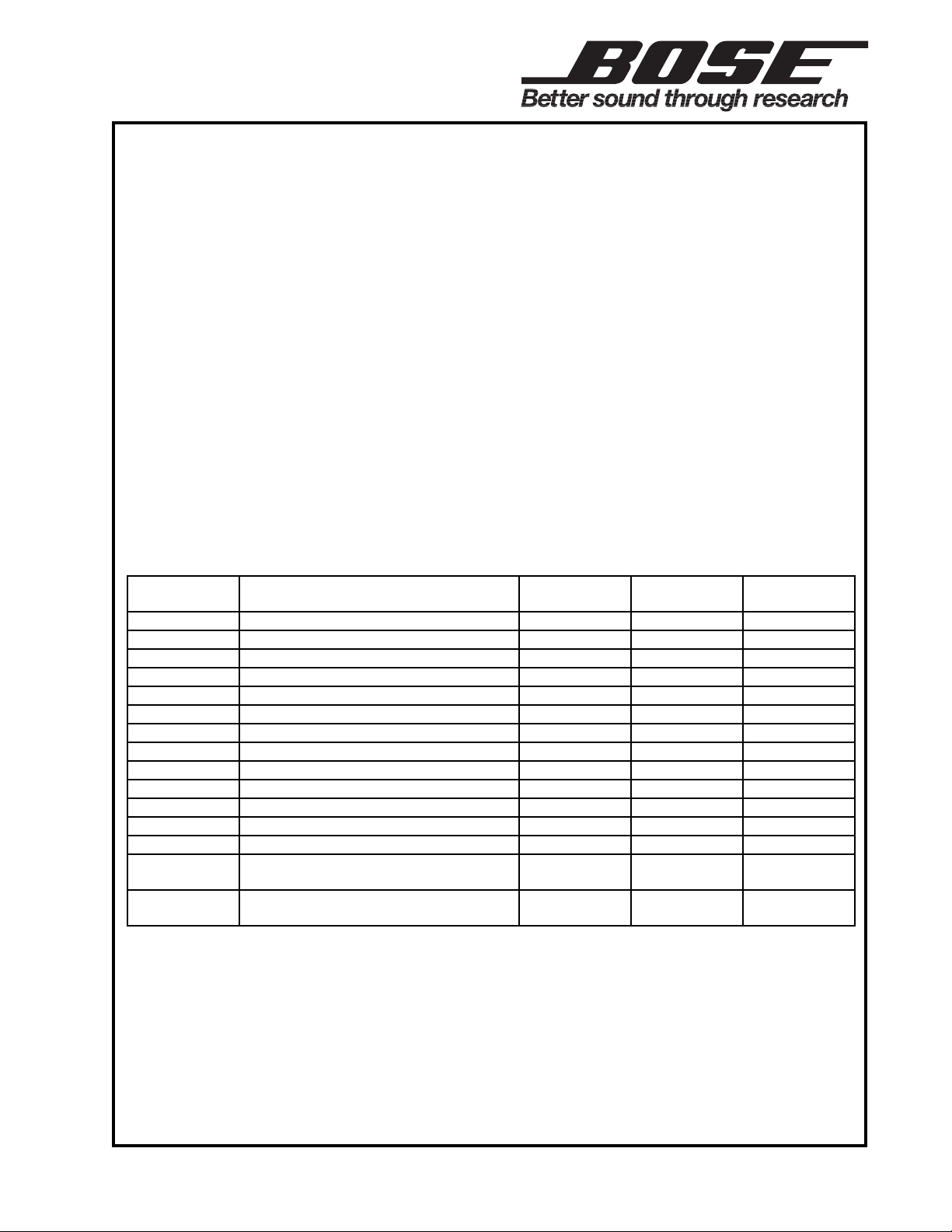
Some of the part numbers listed in the AmPlus 50 and 100 Business Music Amplifier service
manual, part number 194101 have changed.
These changes apply to units built with PCB P/N: 187932 Rev. 4 and later. The revision level of
the PCB is located in a triangle on the topside of the board near connector J7B.
See the table below for a listing of the affected parts. Make a note of these changes in your
AmPlus 50 and 100 Business Music Amplifier service manual, part number 194101.
See the attached schematic sheets for the schematic diagram changes.
Refer to the back of this sheet for the Test Procedures that have changed as a result of these
part changes.
AmPlus 50 and AmPlus 100 Amplifiers
®
Reference
Designator
C256 22uF, EL, 105, 50V, 20% - 137126-220 2
C257 22uF, EL, 105, 50V, 20% - 137126-220 1, 2
R200 10.0K, 0805, 1/10W 133625-1002 133625-1582 3
R220 10.0K, 0805, 1/10W 133625-1002 133625-1582 1, 3
R241 30.1K, 0805, 1/10W 133625-3012 133625-5621 1, 3
R244 30.1K, 0805, 1/10W 133625-3012 133625-5621 1, 3
R326 2.0K, 0805, 1/10W 133625-6191 133625-2001 3
R358 2.0K, 0805, 1/10W 133625-6191 133625-2001 1, 3
D204 SWITCHING, 75V, 200mA - 148562 2
D205 SWITCHING, 75V, 200mA - 148562 1, 2
- SCREW, 6-32 X .5, MACH, XREC 190623-008 198422-008 3
- LIT KIT, AMPLUS 50/100 191954 191936 3
- MANUAL, OWNER'S, AMPLUS 190652 - 4
- INSTALLER'S GUIDE, MULTILANGUAGE (PART OF 191936)
- SCREW, 8-32, PAN (INCLUDED
IN P/N: 191909, RACK MNT. KIT)
Notes: 1. This part is not used on the AmPlus 50 amplifier.
2. This part has been added.
3. This part has been changed.
4. This part has been deleted.
Description Old Part
Number
- 187957 2
- 181745-08 2
New Part
Number
Note
ECNs: 23846, 23849, 24250, 25314, 25800
Date Issued: 5/99
©
1999 Bose Corporation
Supplement
Part Number 194101-S4 Rev. 00
Page 2
Note: Use the following tests for units built with PCB P/N: 187932 Rev. 4 and later.
The revision level of the PCB is located in a triangle on the topside of the board near
connector J7B.
On the AmPlus™ 100 amplifier, the change in value of resistors R241 and R244 as listed on
the front of this sheet affects the gain level of the Channel 1 and 2 Line Outputs. As a result,
the Gain Test on page 22 of the AmPlus 50 and 100 service manual, part number 194101
has changed as follows. Use the test setup parameters on page 21 of the service manual.
1. Gain Test; Source Input to Line Output
1.1 Apply a 100mVrms, 1kHz signal to the Channel 1 and 2 Source Inputs at J1.
1.2 Measure the output level at the Channel 1 and 2 Line Outputs at J5.
1.3 The output level at J5 should be -10.5 dBV ± 1.5 dB.
Note: The information in parentheses applies to the AmPlus 100 amplifier only.
On the AmPlus 50 (and 100) amplifiers, the change in value of resistor(s) R326 (and R358)
as listed on the front of this sheet affects Channel 1 (and 2) output levels. As a result, the
Bass Performance Test on page(s) (24 and) 30 and the High Pass Filter Test on page(s)
(25 and) 30 of the AmPlus 50 and 100 service manual, part number 194101 have changed
as follows. Use the test setup parameters on page(s) (21 and) 26 of the service manual.
9. (10.) Bass Performance Test
9.1 (10.1) Set up the unit under test as listed in the Test Setup Notes section.
9.2 (10.2) Apply a 31.5mVrms, 1kHz signal to the Signal Input jacks at J1.
9.3 (10.3) Reference a dB meter to the output level. This is the reference level.
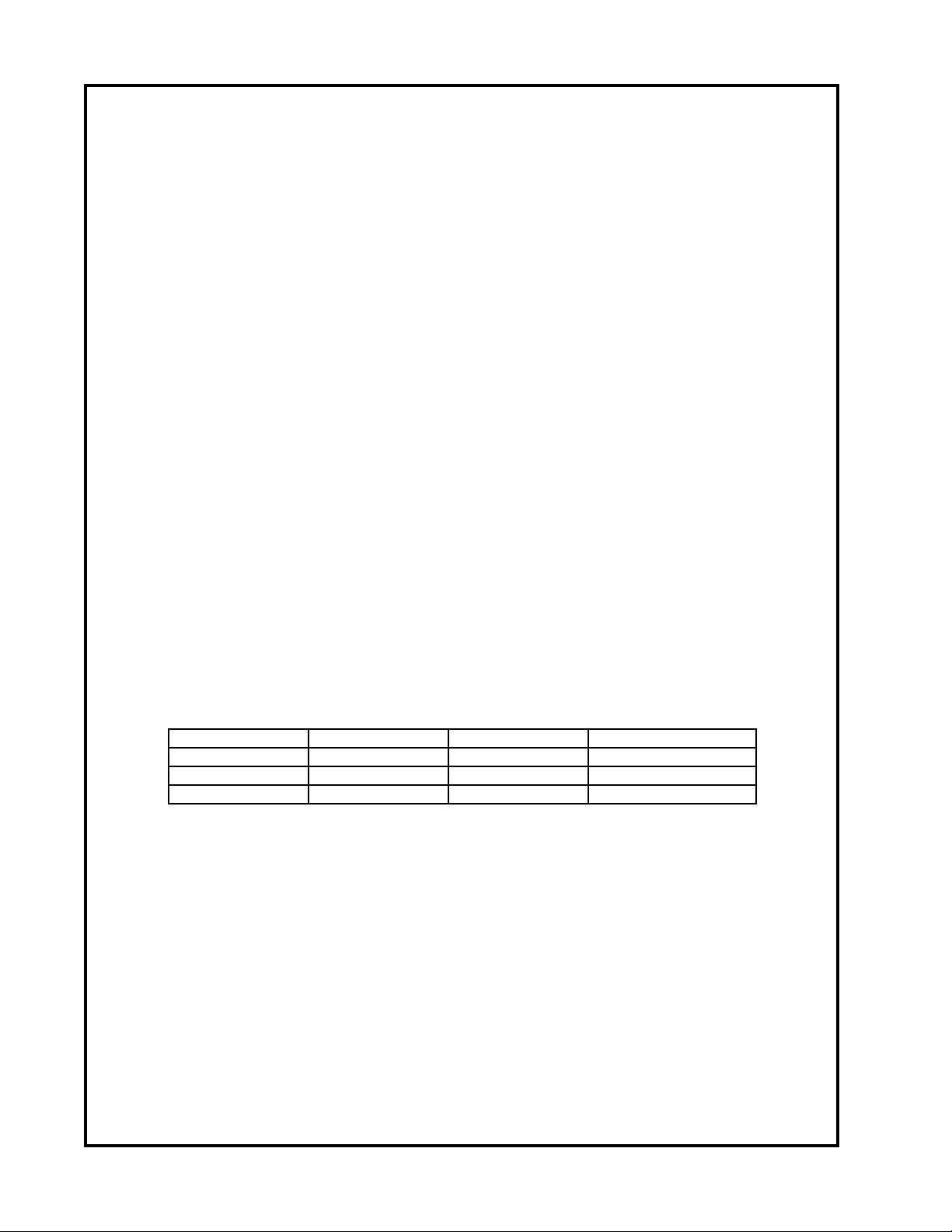
9.4 (10.4) Perform the 20Hz and 100Hz tests as listed in Table (7 or) 13 below.
Test Name Frequency Input (J1) Output (J6)
Bass, 1kHz 1kHz 31.5mV 0dBr ± 0.1dB
Bass, 20Hz 20Hz 31.5mV -2.5dBr ± 2dB
Bass, 100Hz 100Hz 31.5mV +13.0dBr ± 2dB
Table (7 or) 13. Bass Performance Tests
10. (11.) Channel 1 High Pass Filter Test
10.1 (11.1) Set up the unit under test as listed in the Test Setup Notes section.
10.2 (11.2) On the main PCB, place the High Pass Filter switch (S4) to the HPF IN position.
10.3 (11.3) Apply a 31.5mVrms, 1kHz signal to the Channel 1 Source Input.
10.4 (11.4) Reference a dB meter to this output level.
10.5 (11.5) Apply a 31.5mVrms, 50Hz signal to the Channel 1 Source Input.
10.6 (11.6) Measure the output at Channel 1.It should be -7.0dBr ± 3dB (balanced inputs),
or +28.0dBr ± 3dB (unbalanced inputs).
 Loading...