

Page 1

CONTENTS
Safety Information............................................................................................................................ 3
Electrostatic Discharge Sensitive (ESDS) Device Handling ........................................................ 4
Warranty Information....................................................................................................................... 4
Table 1. Amplifier Comparison Chart................................................................................................4
AmPlus™ 100 Amplifier Specifications ......................................................................................... 5
AmPlus 50 Amplifier Specifications............................................................................................... 6
AmPlus 100 Theory of Operation .............................................................................................. 7-10
AmPlus 50 Theory of Operation ................................................................................................... 11
Figure 1. AmPlus 100 Amplifier block diagram............................................................................... 12
Figure 2. AmPlus 50 Amplifier block diagram................................................................................. 13
AmPlus 100 Amplifier Controls................................................................................................ 14-15
AmPlus 50 Amplifier Controls....................................................................................................... 16
Disassembly/Assembly Procedures ....................................................................................... 17-18
Figure 3. AmPlus 100 Amplifier exploded view .............................................................................. 19
Figure 4. AmPlus 50 Amplifier exploded view ................................................................................ 20
AmPlus 100 Test Setup Parameters............................................................................................. 21
Table 2. AmPlus 100 Initial Switch Settings ................................................................................... 21
Table 3. AmPlus 100 Signal Inputs table........................................................................................ 21
Table 4. AmPlus 100 Signal Outputs table..................................................................................... 21
AmPlus 100 Test Procedures................................................................................................... 22-25
Table 5. Source Input to 70/100V Speaker Output test table ......................................................... 22
Table 6. Source Input to 4Ω Speaker Outputs ............................................................................... 24
Table 7. Bass Performance tests ................................................................................................... 24
AmPlus 50 Test Setup Parameters ............................................................................................... 26
Table 8. AmPlus 50 Initial Switch Settings ..................................................................................... 26
Table 9. AmPlus 50 Signal Inputs table.......................................................................................... 26
Table 10. AmPlus 50 Signal Outputs table ..................................................................................... 26
AmPlus 50 Test Procedures .....................................................................................................27-30
Table 11. Source Input to 70/100V Speaker Output test table ....................................................... 27
Table 12. Source Inputs to 4Ω Speaker Output ............................................................................. 29
Table 13. Bass Performance tests ................................................................................................. 29
Installation Diagram Notes:........................................................................................................... 31
Figure 5. AmPlus 100 Simple Mono Installation............................................................................. 32
Figure 6. AmPlus 100 Large Mono Installation using Mixer Feature.............................................. 33
Figure 7. AmPlus 100 70/100 Volt Mode/Model 1B Acoustimass
Figure 8. AmPlus 100 Installation with Two 70/100V Listening Zones........................................... 35
Figure 9. AmPlus 50 Simple Mono Installation............................................................................... 36
Part List Notes................................................................................................................................ 37
Main Part List AmPlus 100 Amplifier (see Figure 10) ................................................................. 38
Figure 10. AmPlus 100 Amplifier exploded view ............................................................................ 39
Main Part List AmPlus 50 Amplifier (see Figure 11).................................................................... 40
Figure 11. AmPlus 50 Amplifier exploded view .............................................................................. 41
Electrical Part List..................................................................................................................... 42-46
Resistors ................................................................................................................................... 42-43
Capacitors ................................................................................................................................. 43-44
Diodes ............................................................................................................................................ 44
Transistors...................................................................................................................................... 44
Integrated Circuits .......................................................................................................................... 45
Miscellaneous ........................................................................................................................... 45-46
®
Bass Module Installation......... 34
1
Page 2

CONTENTS
This service manual has been updated with information from supplement 194101-S1.
This affects part numbers for C610 and C611.
AmPlus™ 50 and 100 Accessory Notes....................................................................................... 47
Table 14. AmPlus 50 and 100 Amplifiers and Accessories............................................................. 47
Packing List Power Amplifier Accessory Kit (see Figure 12) .................................................... 48
Figure 12. Accessory Kit Packing Diagram.................................................................................... 48
Part List Remote Volume Control (see Figure 13)....................................................................... 49
Figure 13. Remote Volume Control exploded view........................................................................ 49
Packing List AmPlus 50 and 100 Amplifier (see Figure 14) ....................................................... 50
Figure 14. AmPlus Series Amplifier Packing Diagram ................................................................... 50
Part List AmPlus 100 Amplifier Accessory Transformer (see Figure 15).................................. 51
Figure 15. AmPlus 100 Accessory Transformer exploded and packing view ................................. 51
Part List AmPlus 50 and 100 Amplifier Rack Mount Accessory Kit (see Figure 16) ................ 52
Figure 16. AmPlus 50 and 100 Amplifier Rack Mount Accessory Kit ............................................. 52
Device Pin-out Diagrams.......................................................................................................... 53-57
Troubleshooting Tips..................................................................................................................... 58
CAUTION: THE AMPLUS 100 AND AMPLUS 50 AMPLIFIERS CONTAIN
NO USER SERVICEABLE PARTS. TO PREVENT WARRANTY INFRACTIONS,
REFER SERVICING TO WARRANTY SERVICE STATIONS OR FACTORY
SERVICE.
PROPRIETARY INFORMATION
THIS DOCUMENT CONTAINS PROPRIETARY INFORMATION OF
®
BOSE
CORPORATION WHICH IS BEING FURNISHED ONLY
FOR THE PURPOSE OF SERVICING THE IDENTIFIED BOSE
PRODUCT BY AN AUTHORIZED BOSE SERVICE CENTER OR
OWNER OF THE BOSE PRODUCT, AND SHALL NOT BE
REPRODUCED OR USED FOR ANY OTHER PURPOSE.
2
Page 3

SAFETY INFORMATION
1. Parts that have special safety characteristics are identified by the symbol on
schematics or by special notes on the parts list. Use only replacement parts that have
critical characteristics recommended by the manufacturer.
2. Make leakage current or resistance measurements to determine that exposed
parts are acceptably insulated from the supply circuit before returning the unit
to the customer. Use the following checks to perform these measurements:
A. Leakage Current Hot Check
(1) With the unit completely reassembled, plug the AC line cord directly into a 120V
AC outlet. Do not use an isolation transformer during this test. Use a leakage
current tester or a metering system that complies with American National
Standards Institute (ANSI) C101. "Leakage Current for Appliances" and
Underwriters Laboratories (UL) 1492 (71).
(2) With the unit AC switch first in the ON position and then in the OFF position,
measure from a known earth ground (metal water pipe, conduit, etc.) to all
exposed metal parts of the unit (antennas, handle bracket, metal cabinet,
screwheads, metallic overlays, control shafts, etc.), especially any exposed
metal parts that offer an electrical return path to the chassis.
(3) Any current measured must not exceed 0.5 milliamp.
(4) Reverse the unit power cord plug in the outlet and repeat test.
ANY MEASUREMENTS NOT WITHIN THE LIMITS SPECIFIED HEREIN
INDICATE A POTENTIAL SHOCK HAZARD THAT MUST BE ELIMINATED
BEFORE RETURNING THE UNIT TO THE CUSTOMER.
B. Insulation Resistance Test Cold Check
(1) Unplug the power supply and connect a jumper wire between the two prongs
of the plug.
(2) Turn on the power switch of the unit.
(3) Measure the resistance with an ohmmeter between the jumpered AC plug
and each exposed metallic cabinet part on the unit. When the exposed
metallic part has a return path to the chassis, the reading should be
between 1 and 5.2 Megohms. When there is no return path to the chassis, the
reading must be "infinite". If it is not within the limits specified, there is the
possibility of a shock hazard, and the unit must be repaired and rechecked
before it is returned to the customer.
3
Page 4
ELECTROSTATIC DISCHARGE SENSITIVE
(ESDS) DEVICE HANDLING
This unit contains ESDS devices. We recommend the following procedures when repairing,
replacing, or transporting ESDS devices.
• Perform work at an electrically grounded work station.
• Wear wrist straps that connect to the station, or heel straps that connect to conductive floor
mats.
• Avoid touching the leads or contacts of ESDS devices or PC boards even if properly
grounded. Handle boards by the edges only.
• Transport or store ESDS devices in ESD protective bags, bins, or totes. Do not insert
unprotected devices into materials such as plastic, polystyrene foam, clear plastic bags,
bubble wrap, or plastic trays.
WARRANTY INFORMATION
The following products are covered by a 5-year transferable limited warranty.
• Bose
• Equalizer Card
• Optional Opti-Voice
• Optional Source Input expansion card
®
AmPlus™ 100 and AmPlus 50
®
Page card
Table 1. Amplifier Comparison Chart
Features AmPlus 100 AmPlus 50
Inputs (balanced) 2 2
Line Outputs (balanced) 2 None
Outputs
-Channel 1
-Channel 2
-70V
Option Cards
-Opti-Voice® Page Card
-Opti-Source™ Card
-EQ Cards (various)
65 Watts
65 Watts
100 Watts
Yes
Yes
Yes, 2
70 Watts
None
50 Watts
Yes, 1
No
No
4
Page 5

AMPLUS™ 100 AMPLIFIER SPECIFICATIONS
Power Output
Stereo: 65W per channel into 4Ω
50W per channel into 8Ω
70V bridged mono: 100W into 98Ω
Ω: 50W @ 70V output into 98Ω
70V/4
65W @ Ch2 output into 4Ω
Input Sensitivity
315mV required to drive both channels
to full power in any mode.
Input Attenuation
0dB to -
∞
Input Impedance
32kΩ balanced, 11kΩ unbalanced
Line Output Impedance
600Ω
Line Output Distortion
≤0.2%
Frequency Response
(active EQ bypassed)
4Ω output: 40Hz - 16kHz, ±1dB
70V output: 60Hz - 16kHz, ±1dB
Special Features
Remote volume control
Turn on/off muting
Clip detection and limiter
Short circuit protection
DC offset protection
Thermal limiting
Stable into reactive loads
RFI protection
UL and TUV approvals
Terminations
Inputs and outputs are quick-connect
terminal blocks
Optional Accessories
EQ Cards (Model 1B, Models 8 and 25/32)
Source Card
Page Card
Operating Temperature Range
(passively cooled)
12˚F to 120˚F (-10˚C to +50˚C)
AC Power Consumption
350 Watts max, 100/120Vac, 50-60Hz
350 Watts max, 220/240Vac, 50-60Hz
THD@ Rated Power
4Ω output: ≤2% THD (40Hz - 16kHz)
70V output: ≤2% THD (60Hz - 16kHz)
Hum and Noise
Line output: 92dB
Power amplifier output: 80dB below rated
output with 4Ω load
Controls
Inputs 1 and 2, input attenuation, remote
volume, bass adjust 1 and 2, Input Mode
and Amplifier Mode switches.
LED Indicators
Power: front panel
Size
(Desk Mount)
17"W x 10"D x 3 3/4"H
(43.2 x 25.4 x 9.52 cm)
(Rack Mount, chassis supported)
19"W x 10"D x 3 3/4"H
(48.3 x 25.4 x 9.52 cm)
Weight
25 lb (11.3 kg)
Associated Equipment
Rack mount kit
Second zone transformer
5
Page 6

AMPLUS™ 50 AMPLIFIER SPECIFICATIONS
Power Output
70V Mono: 50W into 98Ω
Ω Mode: 70W outputs into 4Ω
4
Input Sensitivity
315mV required to drive amplifier to full
power in any mode.
Input Attenuation
0dB to -
∞
Input Impedance
32kΩ balanced, 11kΩ unbalanced
Input/Output Configurations
1. Mono into 4Ω load
2. Mono into 70V load
3. As an extension to the AmPlus 100
amplifier
Frequency Response
(active EQ bypassed)
4Ω output: 40Hz - 16kHz, ±1 dB
70V output: 60Hz - 16kHz, ±1 dB
THD@ Rated Power
4Ω output: ≤2% THD (40Hz - 16kHz)
70V output: ≤2% THD (60Hz - 16kHz)
Hum and Noise
Power amplifier output: 80dB below rated
output with 4Ω load
Controls
Inputs 1 and 2, input attenuation, remote
volume, bass adjust affects bandwidth of
50Hz - 150Hz by 0 - 10dB, Amplifier Mode
switches.
Special Features
Remote volume control
Turn on/off muting
Clip detection and limiter
Short circuit protection
DC offset protection
Thermal limiting
Stable into reactive loads
RFI protection
UL and TUV approvals
Terminations
Inputs and outputs are quick-connect
terminal blocks
Optional Accessories
EQ cards (Model 1B, Models 8 and 25/32)
Operating Temperature Range
(passively cooled)
12˚F to 120˚F (-10˚C to +50˚C)
AC Power Consumption
200 Watts max, 100/120Vac, 50-60Hz
200 Watts max, 220/240Vac, 50-60Hz
Size
(Desk Mount)
17"W x 10"D x 3 3/4"H
(43.2 x 25.4 x 9.52 cm)
(Rack Mount, chassis supported)
19"W x 10"D x 3 3/4"H
(48.3 x 25.4 x 9.52 cm)
Weight
20 lb (9.1 kg)
LED Indicators
Power: front panel
Associated Equipment
Rack mount kit
6
Page 7

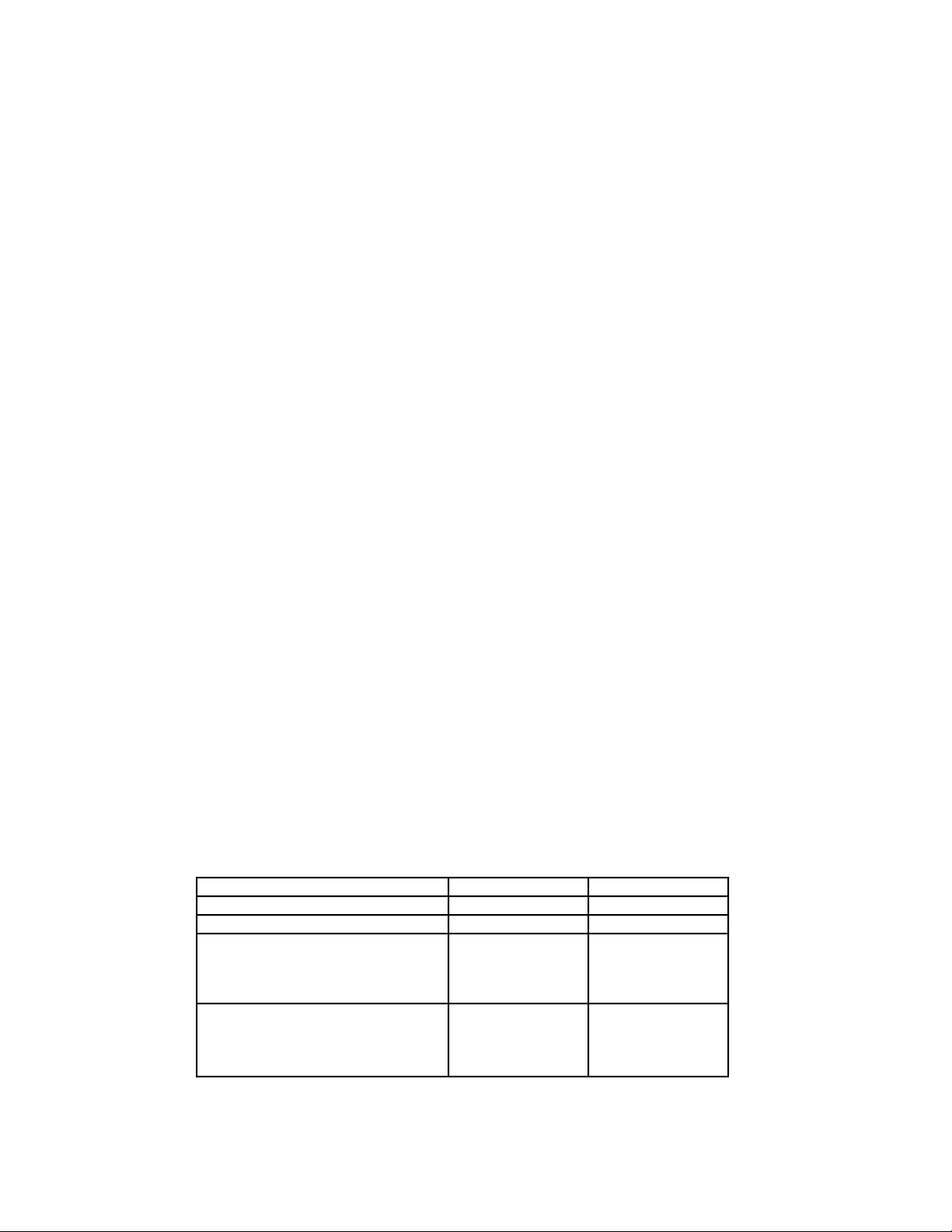
AMPLUS™ 100 THEORY OF OPERATION
Introduction:
The AmPlus 100 Business Music Amplifier is a two channel amplifier intended for business
music and other installed sound systems. Its two inputs pass through the Opti-Voice
Opti-Source™ Option Cards and Equalizer cards, if they are installed. These cards expand the
number of inputs and outputs of the basic AmPlus 100, adding special features of paging, source
selection, and priority override.
Sheet 1 of 3
Refer to the AmPlus 100 schematic diagram, sheet 1 of 3 for the following information.
Note: The designators inside the brackets “[ ]” are the schematic grid coordinates which
are provided in order to make it easier to locate components on the schematic sheet
indicated in the description.
The Channel 1 and Channel 2 Inputs at J1 [D8] are the "A" inputs on the AmPlus 100
and accept line level sources. U100A [D7] and U101B [C7] are unity gain, differential input
amplifiers, with inputs well protected against RF and ESD. Ch 2 coming from U101B can
pass through S1 [D7], the Mono/Dual Mono/2-Ch switch, in the 2-Ch position. In other
positions of S1, Ch 2 is ignored unless S7 [C7], the 2-Ch/Mixer switch, is in the Mixer
position, in which case Ch 2 and Ch 1 are mixed in the proportion set by R1 and R2, the
Ch 1 and Ch 2 gain trim switches. After buffers U106A/B, the Ch 1 and Ch 2 signals are
presented to one of the two inputs of U102 [D6] and U103 [C6], op amps with a pair of
input stages and a selector mechanism, acting as a selector switch. If no option card is in
the #1 position at J2 [C7], U102/103 pass the Ch 1 and Ch 2 A input signals straight
through; if either a source or a page option card is in the #1 slot at J2, its output will be
selected to pass forward into the AmPlus 100 signal path.
If an option card is installed in the #1 slot at J2, then the Ch 1 and Ch 2 A input signals
are sent to the option card, and will be processed on that option card and returned to the
AmPlus 100 along with the other signals contributed by the option card. The switching
action of U102/103 is controlled by the DC level on pin 1. Normally, with no option card in
the #1 slot at J2, this pin is pulled high, but when an option card is in place it shorts J2-5,
pulling U102/103 pin 1 toward ground.
®
Page and
Continuing forward on Sheet 1, [coordinates 5D and 5C], the Ch 1 and Ch 2 signals
encounter another pair of switched op amps, U104/105 and the option card #2 connector
at J3 [C6]. Signal flow here is handled in the same manner as around option card #1: if no
option card is installed in slot #2 at J3, the signals pass through; otherwise, they enter the
option card and are processed along with that card's sources before being returned to the
main AmPlus 100 signal path.
Equalizer cards can be placed in J9 [D5] (for Ch 1) and in J10 [C5] (for Ch 2). If there is
no EQ card in J9, the output from U104 passes through the unity gain buffer U100B, but
if there is an EQ card, it "overrides" the signal from U104, substituting equalized audio from
the EQ card. A similar arrangement for Ch 2 uses U101C. Special switching in the Ch 2
path after U101C allows the use of a single EQ card in the J9 slot in the cases where the
source is being handled in mono or dual mono (in dual mono, R3, the Zone 2 Trim, is
engaged). When the switch S1 is in the Mono or Dual Mono position, the Ch 1 signal is
taken through an inverting stage (U101A) and passed to the Ch 2 path. Inverting the
signal phase for the CH2 output compensates for the fact that the connector for the Ch 1
output results in the Ch 1 speaker signal also being inverted. U105 provides this phase
inversion for Ch 2 signals when S1 is in the two channel mode.
7
Page 8

AMPLUS™ 100 THEORY OF OPERATION
Sheet 1 of 3 (continued)
Note that the U104/105 output is also taken directly, before the EQ card, to two of the
volume control VCAs (U204A, D), for use as Line Outputs. U204B, C implement the
volume control for the main CH1 and CH2 paths that will move forward in the AmPlus 100
itself.
U204 [C2] is a quad, current in /current out, voltage controlled amplifier. Sections U204A,
D, pins 4 and 13, (line output) are controlled only by the remote volume control action,
whereas sections U204B, C, pins 5 and 12, (main path) are also controlled, in an OR'd
fashion, by the signals CLIP / SC1 [D1] and CLIP / SC2 [A1]. The CLIP / SC signals
become active when the power amplifier is clipping and/or attempting to drive a short
circuit. This reduces the volume control setting, preventing distortion when a user plays
the system too loud, as well as reducing power dissipation when there is a short circuited
load.
Connector J4 [A8] ties one or two 10K rheostat-connected remote volume control
potentiometers into Q201/221, whose outputs are steered by S5 [B4] (1 Remote / 2
Remotes) into U200 A, B, C, D, [B, C3] which inverts and scales the voltages to the
appropriate range needed to control the VCAs. U203A, B [B4] buffer the CLIP / SC
signals and OR them into the appropriate sections of U204 via diodes D200, 203. J12
[A8] is reserved for a possible future level control option.
U201A, U202B [B / C1] are the line output buffers, whose outputs are passed through
series R/shunt C elements for RFI management. At the junction of the resistors, FETs
Q401, 403 [A, B6] provide a power-up/power-down mute so that equipment connected to
the line outputs will not experience thumps or pops.
Sheet 2 of 3
Refer to the AmPlus 100 schematic diagram, sheet 2 of 3 for the following information.
Sheet 2 concludes the processing of the Ch 1 and Ch 2 signals, preparing them for the
power amplifiers. Circuits on this sheet deal largely with dynamic EQ and switchable EQ,
all directed toward the bass region. The CH1 signal (DYNEQ1) entering Sheet 2 [C8] is
sent in parallel to five points. Two paths pass through S4 [D6], which selects HP Out
(150Hz high pass filter off) or HP In (150Hz high pass filter in). Another path, through R4
[D8], Ch 1 Bass Boost Adjust (50-150Hz) and a bandpass filter, U300B [D5], determines
how much bass boost will be present. The signals out of S4 and the bandpass filter are
summed in U300A [C4], along with yet another equalized signal.
To develop Dynamic EQ (an equalization where the amount of bass boost applied
varies inversely with the signal level), the DYNEQ1 signal [C8] is fed to circuits
composed of U300D, Q300, Q301, Q302, U303, U300C, U302A, and U304. U300C,
Q300, Q301, Q302 develop a current proportional to the rectified signal level. This current
enters the control pin of U302A, a transconductance amplifier, whose output current is
multiplied by its control current. U302A is in the negative feedback loop of U300D, which
now passes the signal DYNEQ1 with a gain controlled inversely by its own level. At
small signals, the gain is the highest. Next, the output of U300D passes through one of
two bandpass filters, shaping the signal into a bass boost signal. U304 [C4] selects
between two bandpass filters, one centered at 55Hz and appropriate for the Free Space
Model 1B Acoustimass® Module, the other at 90Hz, appropriate for full range systems,
such as the Model 8, Model 25 and Model 32 Loudspeakers.
®
Switching to the 55Hz bandpass filter is automatically handled by sensing when a
Model 1B EQ card has been inserted in the Ch 1 EQ card socket [J9 on sheet 1 at
coordinates D5] (signal EQGND [D1, sheet 1, and B8, sheet 2] is shorted to ground by
the Model 1B EQ card when it is plugged in).
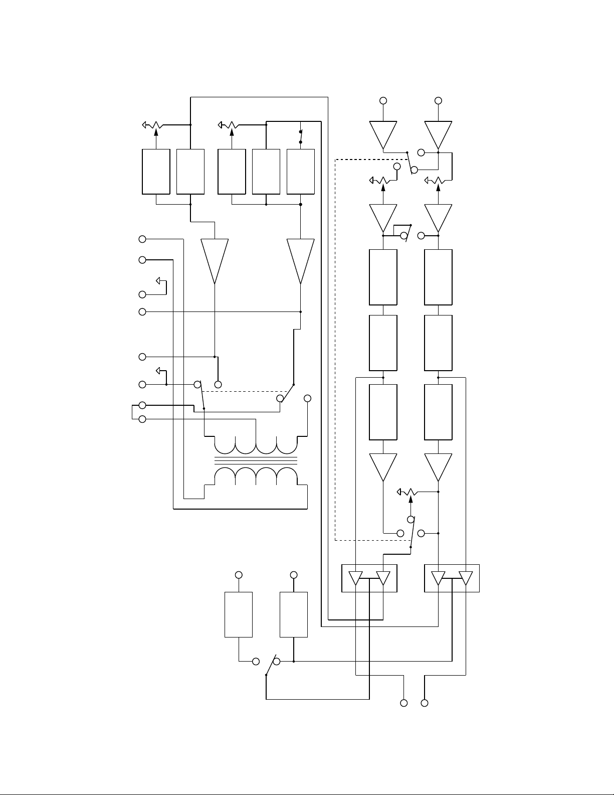
8
Page 9

AMPLUS™ 100 THEORY OF OPERATION
Sheet 2 of 3 (continued)
Finally, the bass boost signal from the dynamic EQ path rejoins the other signals, (the
full range signal, high pass filtered if S4 is in the HP IN position, via S4 and R381, and the
manually adjusted bass boost signal via R4 and U300B) in the summing stage U300A
[C4]. Now, at last, the Ch 1 and Ch 2 signals are ready to enter the power amplifiers, via
connectors J7B [D1] and J8B [B1]. Note that Ch 2 is handled identically by the
companion circuits shown below Ch 1's circuits.
Connectors J7B / J8B send the power amplifier power rails (±20V and ±40V) as well as
±12V power and various grounds. The CLIP / SC signals are returned from the power
amplifiers via these connectors as well.
DC Offset detection circuits
Circuits that watch for excessive DC offsets of the power amplifier outputs are seen at
coordinates C1. Ultimately, these circuits control the operation of relay K600 [sheet 3, B4]
whose contacts enable the ±40V supply relays when K600 is energized. The op amp
circuits U700 and U701 [sheet 2, C2] watch the Ch 1 and Ch 2 power amplifier outputs
for DC offsets greater than about 2.4V. However, in order to keep the relay energized,
other conditions must also be met. The ±40V rails and the ±12V rails must each be within a
certain degree of symmetry. The Ch 1 power amplifier output is low pass filtered to pass
only the DC offset component and is full wave rectified in U700B [C1] and U701A [C2]. A
derived center tap from the ±40V supplies is also brought into the full wave rectifier B600
[sheet 3, B4]. The rectifier output is then compared to -2.4V in U701A [sheet 2, C2] (an op
amp used as a comparator). If the absolute value of the offset is less than 2.4V, U701A's
output is high, which holds Q700 off. Q700 off ensures that Q600 / 601 [sheet 3, B2] can
be on, which allows current to flow through the K600 relay coil, energizing it, and thus
allowing ±40V to be applied to the power amplifiers.
At coordinates [A, B 1, 2] on Sheet 2 of 3, the power amplifier output wiring is detailed.
The power amplifier outputs are always tied to the Ch 1, 2 ± output connector pins,
whether the amplifier mode switch S6 [A2] is in the Bridged or the 2 Channel position.
However, if S6 is in the Bridged position and if a jumper has been placed between the
two XFR CT pins, then the Ch 1 signal and the Ch 2 signals drive the output transformer
primary in concert, potentially delivering in excess of 100 watts to the 70 / 100V output
pins. Jumpers J409, 410 [sheet 2, A1] select between 70V and 100V operation.
Sheet 3 of 3
Refer to the AmPlus 100 schematic diagram, sheet 3 of 3 for the following information.
Sheet 3 outlines the power amplifier and power supply circuits. Channel 1 circuitry is
explained below, Channel 2 operation is identical. The Ch 1 amplifier is built around a
power amplifier IC, U500 [C6], augmented by class G transistors. For U500 audio output
levels between about ±20V, U500 acts on its own, with its power coming from the ±20V
rails via D502 / 509 [C, D5]. When the input signal rises, demanding an output in excess
of about ±20V, transistors Q500, 501, 502 (positive rail) and Q503, 504, 505 (negative
rail) come into play. Each of these transistor trios is driven by the input signal, via steering
diodes D501, 507, and turn on as the higher signal peaks dictate. When Q502 is on, it
handles part of the power dissipation by passing the loudspeaker current through power
devices in series with the U500 rails. This allows U500 to deliver higher voltage, higher
current power to its load while still staying within acceptable IC power dissipation limits.
For those portions of the audio output waveform greater than about ±20V, the class G
power transistors Q502, Q505 dissipate part of the power.
9
Page 10

AMPLUS™ 100 THEORY OF OPERATION
Sheet 3 of 3 (continued)
The power amplifier is equipped with a clip detector circuit, implemented with U503 [D7],
an LM311 comparator, and associated parts. The comparator watches the differential input
voltage at the power amplifier input pins and compares it to 120mV. If the power amplifier,
a feedback amplifier, is for any reason unable to deliver the output voltage requested by
the source, linear operation ceases and an error voltage develops across its input pins.
Inability to deliver the requested output voltage can occur if there is a short circuit on the
amplifier output, a DC offset from some kinds of failures, or from overdriving the amplifier.
Whatever the cause, if the input error voltage exceeds the threshold, the LM311 output
will go low, toward the -12V supply. Active (low-going) CLIP / SC signals are fed through
J7 pin 12 back to the VCA volume control IC, U204 on Sheet 1 [C2], where they turn the
gain down to eliminate the stress of the overload situation. If the power amplifier starts to
clip, the feedback signal acts as a limiter to keep the amplifier out of the distorted clipping
region.
The AmPlus 100 power supply can be configured for either 120V (60Hz) or 230V (50 or
60Hz) AC mains by the appropriate placement of jumpers J603, J605, J606. This is
shown on Sheet 3 at coordinates A6, 7, and 8. The AC mains voltage is stepped down
and rectified, creating unregulated ±40V and ±20V rail pairs for use by the power amplifier.
Regulators U600, 601 [A3] derive ±12V from the ±20V supplies for use by the op amp
circuits. The bridge rectifiers B600, and B601 are fused against overload, while the ±12V
supply is fused by 1/4 watt resistors R602, and R603. Also on Sheet 3, [B2], are Q600
and Q601, the relay drive transistors controlled by RELAY, from Sheet 2.
10
Page 11

AMPLUS™ 50 THEORY OF OPERATION
Introduction:
The AmPlus 50 Business Music Amplifier is a single channel amplifier in most ways
identical to the AmPlus 100. Both amplifiers are built in similar chassis using the same
PCBs, but most of the Ch 2 parts are omitted in AmpPlus 50.
Note: Refer to the appropriate AmPlus 50 Schematic diagram sheet as indicated below
for the following information.
Note: The designators inside the brackets “[ ]” are the schematic grid coordinates which
are provided to make it easier to locate components on the schematic sheet indicated in
the description.
Note: The components not used in the AmPlus 50 Amplifier are indicated on the schematic
diagram as optional (opt).
Sheet 1 of 3
The discussion for the AmPlus 100 applies to the AmPlus 50, with a few
exceptions. The Ch 1 and Ch 2 at J1[D8] inputs are summed after their input buffers
U100 and U101 [C/D7] and are passed through the Ch 1 path. There are no connectors
or slots for the #1 [J2] or #2 [J3] option cards, nor for the Ch 2 EQ card [J10]. There are no
line outputs, and only one remote volume control input [J4]. Only the DYNEQ 1 output
signal from Sheet 1 passes to Sheet 2. Only the CLIP / SC1 signal is passed into
Sheet 1.
Sheet 2 of 3
The discussion for the AmPlus 100 applies to the AmPlus 50, with a few exceptions.
Only the Ch 1 path of dynamic and fixed EQ circuits is populated, and only the Ch 1
power amplifier connector is provided. The output connector provides either 4 ohm or
70/100V CV, (Constant Voltage) outputs, as selected by S6 for Ch 1.
Sheet 3 of 3
The AmPlus 50 version is identical except that only the Ch 1 power amplifier module is
installed.
11
Page 12
(R5)
Gain
Ch. 2
Bass
(R4)
Gain
Ch. 1
Bass
(S4)
Filter
Switch
Pass
High-
Channel 2
Input
J1
section1 of 2
Switch (S1)
Input Mode
Mono
Channel 1
Input
Bass Boost
+ -
70V
Figure 1. AmPlus™ 100 Amplifier Block Diagram
+ -
CH. 1
Amplifier
Outputs
J6
CH. 2
CT
Power
+ -
XFMR
Dynamic
EQ
2 Ch.
Bass Boost
Power Amp 2
70V Bridged
Switch
(S6)
EQ
Mode
Amp.
Dynamic
Power Amp 1
2 Ch.
High Pass
Filter
70V Bridged
Level (R2)
Ch. 2
2 Ch.
(S7)
2-Ch.
Option Card 1
Channel 2
Option Card 2
Channel 2
EQ Card 2
Mono
Dual
Switch
Mix
Mixer
Trim (R3)
Zone 2
Option Card 1
Channel 1
Option Card 2
Channel 1
EQ Card 1
Level (R1)
Ch. 1
Remote
Zone 2
Control 2
VCA
2 Remotes
Remote
Zone 1
Assign Switch (S5)
Control 1
Remote Zone
VCA
1 Remote
12
VCA 2
2 Ch.
Switch (S1)
Section 2 of 2
Ch. 2
Mono
Dual
Mono
Input Mode
Ch. 1
J5
VCA 1
Line Outputs
Page 13
(R4)
Ch.1
Gain
Bass
(S4)
Filter
Switch
Pass
High
Channel 2
Input
J1
Channel 1
Input
Power
Amplifier
Outputs
Figure 2. AmPlus™ 50 Amplifier Block Diagram
+ -
70V
J6
+ -
Ch. 1
70V
Bass Boost
4 Ohm
(S6)
Switch
Mode
Dynamic
EQ
Amp
High Pass
Filter
Power Amp 1
70V
4 Ohm
Level (R2)
Ch. 2
Level (R1)
Ch. 1
EQ Card
13
Remote
Zone 1
Control 1
VCA
VCA
Page 14
AMPLUS™ 100 AMPLIFIER CONTROLS
INPUTS A
Ch1 Ch2
+- +-
2Ch
INPUT
MODE
dual
mono mono
LEVEL
Zone 2Ch2Ch1
-6 -6 -6
-10-10 -10
0 0 0-40 dB -40 dB -40 dB
BASS
LEVEL
Ch2Ch1
+10
OFF
OFF
+10
REMOTE
VOLUME
ZONE 1 ZONE 2
LINE OUTPUT
ZONE 1 ZONE 2
+-+-
POWER AMPLIFIER
70V ZONE1
4-16
ZONE 2
4-16
Ω
Ω
+-+-+-
XFR
CT
Inputs - The amplifier comes with two balanced inputs. They can be left and right channels
from a stereo source or two distinct monophonic (mono) sources for 2 - zone applications.
Two mono sources can also be mixed for single zone applications.
Input Mode - This switch determines how the Channel 1 and Channel 2 inputs are presented
to the power amplifier section of the AmPlus 100. There are 3 possible modes.
1. 2 - Channel/Mixer - the inputs remain separate, not summed. Channel 1 and
Channel 2 level potentiometers are active in this mode. Use this mode for:
a. Stereo (2 - channel).
b. Two distinct sources in a two zone application (2 - channel), 1 source per zone.
c. Two distinct sources in a single bridged mono zone (Mix).
MODE
70/100V 2 Ch
BRIDGED
Note: In Mix mode both sources, Channel 1 and Channel 2, are presented to the amplifier
simultaneously. When the internal source mix switch is in the MIX position, the Channel 1
attenuation controls the source connected to the Channel 1 input. The Channel 2 attenuation
controls the source connected to the Channel 2 input.
2. Dual Mono - The Channel 1 and Channel 2 inputs are summed to mono and presented to
the power amplifiers as two mono signals. This mode may also be used when driving a 70V
®
load from the Channel 1 amplifier outputs and a Bose
Model 1B Acoustimass® Bass Module
from the 4Ω Channel 2 outputs - see zone 2 level adjust.
3. Mono Mode - Both inputs, Channel 1 and Channel 2, are summed to mono. Only the
Channel 1 level pot is active.
Level - Channel 1 level adjust - In 2 - channel (stereo) mode, this pot affects the signal level
at the channel 1 low impedance (4Ω) outputs. In dual mono mode, it controls the zone 1 level.
In mono mode, it controls the level of all inputs.
Channel 2 level adjust - In 2-Channel (stereo) mode, this pot controls the signal level at the
channel 2 low impedance (4Ω) outputs. This pot is not active in dual mono or mono modes.
Zone 2 level adjust - This pot is only active when the input mode is dual mono. In this mode,
this pot controls the signal level at the channel 2 low impedance outputs. This pot is a slave to
the channel 1 pot; that is, the channel 1 pot controls the level of both zones in a 2-zone
system. However, the zone 2 pot can be used to fine-tune the bass level when using the
AmPlus 100 to drive a 70V load connected to the 70V output and a Model 1B Acoustimass
Bass Module connected to the channel 2 output. This pot may also be used to fine-tune the
bass level when using the AmPlus 100 to drive a 70V load connected to the 70V output and a
Model 1B Acoustimass Module connected to the channel 2 output.
14
Page 15
AMPLUS™ 100 AMPLIFIER CONTROLS
INPUTS A
Ch1 Ch2
+- +-
2Ch
INPUT
MODE
dual
mono mono
LEVEL
Zone 2Ch2Ch1
-6 -6 -6
-10-10 -10
0 0 0-40 dB -40 dB -40 dB
BASS
LEVEL
Ch2Ch1
+10
OFF
OFF
+10
REMOTE
VOLUME
ZONE 1 ZONE 2
LINE OUTPUT
ZONE 1 ZONE 2
+-+-
POWER AMPLIFIER
70V ZONE1
4-16
ZONE 2
4-16
ΩΩ
+-+-+-
XFR
CT
70/100V 2 Ch
BRIDGED
Bass Level - Use the bass level pots to increase the output level between 50 Hz and 150 Hz.
This is useful for compensating for poor bass cabinet loading or high levels of low-frequency
ambient noise. The channel 1 and channel 2 pots are active in all modes of operation.
Remote Volume - When using the amplifier to power one listening zone, connect the remote
control unit to the zone 1 (+) pin and the ground pin and set the internal remote volume switch
(see figure below) to 1 REMOTE. When using the AmPlus 100 for 2 - zone applications,
connect a second remote to the zone 2 (+) pin and the ground pin and set the internal remote
volume switch to 2 REMOTES.
High Pass
Mix
EQ 1
Filter
MODE
EQ 2
1 Remote
C
2 Remote
Line Outputs - Both line output responses are flat (regardless of whether or not you have
installed active equalizer cards). The remote volume control affects the line output levels. Both
outputs are active in stereo mode. Only zone 1 is active in dual mono and mono modes.
Power Amplifier Outputs - The 70V output becomes active when the amp mode switch is in
the 70V position. In this setup, both AmPlus 100 channels are bridged and provide up to 100
Watts to the 70V speakers.
- When the amp mode switch is in the 2-Channel position and a jumper is placed across the
Xfr. ct. pins, 50 Watts is available at the 70V output and 65 Watts is available at the channel
2 output. (see illustration at top of page)
- With the amp mode switch in the 2-Channel position, both channel 1 and channel 2 supply
65 Watts into a minimum load of 4Ω.
Internal High Pass Switch - When this switch is in the HPF ON position, frequencies below
150Hz are attenuated at 18dB/Oct. This low frequency roll-off occurs on Channel 1 only. Use
this switch for bandlimiting high frequency speakers connected to channel 1 in a bi-amplified
system. For example, the 70V/Model 1B system in Figure 7.
Internal Remote Volume Switch - For one zone applications, this switch should be in the 1
REMOTE position. For two zone applications, this switch should be in the 2 REMOTES
position.
15
Page 16
AMPLUS™ 50 AMPLIFIER CONTROLS
INPUTS A
Ch1
Ch2
+- +-
LEVEL
-6 -6
-10-10
0 0-40 dB -40 dB
BASS
OFF
GAIN
+10
Ch2Ch1
REMOTE
VOLUME
POWER AMPLIFIER
70V
4-16
Ω
+-+-
Inputs - The AmPlus 50 amplifier comes with two balanced inputs. They can be left or right.
Two mono sources can also be mixed. Since the AmPlus 50 is a single channel amplifier, a
stereo source is internally summed to mono.
Level - Channel 1 level adjust - This potentiometer controls the signal level of the channel 1
input source.
Channel 2 level adjust - This potentiometer controls the signal level of the channel 2
input source.
Bass Gain - Use the bass gain pot to increase the output level between 50 Hz and 150 Hz.
This is useful for compensating for poor bass cabinet loading or high levels of low frequency
ambient noise.
Remote Volume - Connect the remote volume control unit to the zone 1 (+) pin and the
ground pin to control the overall level of the amplifier remotely.
MODE
70/100V 4-16
High Pass
Filter
EQ 1
C
Power Amplifier Outputs - The 70V output is active when the amplifier Mode Switch is in the
70V position. The 4Ω output is active when the amplifier Mode Switch is in the 4Ω position.
Internal High Pass Filter Switch - When this switch is in the HPF ON position, frequencies
below 150 Hz are attenuated at 18dB/Oct. Use this switch for bandlimiting high frequency
speakers in a bi-amplified system.
16
Page 17

DISASSEMBLY/ASSEMBLY PROCEDURES
1. Top Cover Removal
Note: Refer to Figures 3 and 4, as
applicable, for the following procedures.
Note: The numbers in the parentheses
correspond to the callouts in Figures 3
and 4.
1.1 Unplug the power cable from IEC
connector on the rear of the amplifier.
1.2 Using a phillips-head screwdriver,
remove the five screws (1) that secure the
top cover (2) to the amplifier chassis (16).
1.3 Lift the top cover straight off.
2. Top Cover Replacement
2.1 Observing orientation, place the top
cover (2) straight down onto the amplifier
chassis (16).
2.2 Using a phillips-head screwdriver,
secure the top cover to the amplifier
chassis using the five screws (1) that
were removed in procedure 1.
3. Main PCB Removal
4. Main PCB Replacement
4.1 Orient the main PCB (8) so that the
connectors are aligned with the rear panel
of the amplifier chassis (16), and slide the
main PCB into place.
4.2 Secure the main PCB to the amplifier
chassis using the six screws (9) removed
in procedure 3.4.
4.3 Reconnect all connectors unplugged
in procedures 3.2 and 3.3.
4.4 Replace the top cover (2) using
procedure 2.
5. Amplifier Module Removal
5.1 Remove the top cover (2) using
procedure 1.
5.2 Unplug the appropriate cable
connector, (J7B or J8B), for the amplifier
module that you wish to remove.
5.3 Remove the two screws (12) that
secure the amplifier module to the amplifier
chassis (16) and lift the amplifier module
straight out.
3.1 Remove the top cover (2) using
procedure 1.
3.2 Unplug all of the cable connectors from
the rear panel of the amplifier.
3.3 On the main PCB (8), unplug the
connectors at J2, J7B, J3, J8B, J602, J601,
J400, J401, and J600.
3.4 Using a phillips-head screwdriver,
remove the six screws (9) that secure the
main PCB to the amplifier chassis (16).
3.5 Lift the main PCB at the edge nearest
the amplifier heatsinks, and slide the PCB
forward, until the main PCB connectors
clear the amplifier rear panel, then lift the
PCB straight up.
6. Amplifier Module Replacement
6.1 Place the amplifier module into the
appropriate spot in the amplifier chassis
(16) and secure it using the two screws
(12) removed in procedure 5.3.
6.2 Plug the amplifier module cable into the
appropriate connector (J7B or J8B) on the
main PCB (8).
6.3 Replace the top cover (2) using
procedure 2.
17
Page 18

DISASSEMBLY/ASSEMBLY PROCEDURES
7. Power Transformer Removal
7.1 Remove the top cover (2) using
procedure 1.
7.2 Unplug the transformer cables at J601
and J602 on the main PCB (8).
7.3 Remove the four nuts (5) that secure
the power transformer (7) to the amplifier
chassis (16).
7.4 Lift the power transformer straight out
of the amplifier chassis.
8. Power Transformer Replacement
8.1 Place the power transformer (7) into the
amplifier chassis (16), aligning it over the
chassis studs.
8.2 Secure the power transformer to the
amplifier chassis using the four nuts (5)
removed in procedure 7.3.
10. Audio Transformer Replacement
10.1 Place the audio transformer (3) into
the amplifier chassis (16) with the wires
facing toward the main PCB (8), aligning it
over the amplifier chassis studs.
10.2 Secure the audio transformer to the
amplifier chassis using the two nuts (5)
removed in procedure 9.3.
10.3 Plug the audio transformer cables
into the main PCB at J400 and J401.
10.4 Replace the top cover (2) using
procedure 2.
8.3 Plug the power transformer cables into
J601 and J602 on the main PCB (8).
8.4 Replace the top cover (2) using
procedure 2.
9. Audio Transformer Removal
9.1 Remove the top cover (2) using
procedure 1.
9.2 Unplug the audio transformer (3) cables
from the main PCB (8) at J400 and J401.
9.3 Remove the two nuts (5) that secure
the audio transformer to the amplifier
chassis (16).
9.4 Lift the audio transformer straight out of
the amplifier chassis.
18
Page 19

(5 PLACES)
1
2
3
(4 PLACES)
12
14
(7 PLACES)
7
5
11
10
(4 PLACES)
4
6
8
(6 PLACES)
9
(2 PLACES)
13
15
16
17
(2 PLACES)
18
Figure 3. AmPlus™ 100 Amplifier Exploded View
19
Page 20

(5 PLACES)
1
2
3
(7 PLACES)
(2 PLACES)
5
4
6
7
8
(6 PLACES)
9
(3 PLACES)
(2 PLACES)
10
11
12
13
14
15
16
17
Figure 4. AmPlus™ 50 Amplifier Exploded View
20
Page 21

AMPLUS™ 100 TEST SETUP PARAMETERS
Table 2. AmPlus 100 Initial Switch Settings
Control Name Reference Designator Default Setting
Input Mode S1 switch Left (2-Channel/stereo)
Source Trim - Channel 1 R1 potentiometer CW (no attenuation)
Source Trim - Channel 2 R2 potentiometer CW (no attenuation)
Zone 2 Trim R3 potentiometer CW (no attenuation)
Bass Adjust - Channel 1 R4 potentiometer CW (full gain)
Bass Adjust - Channel 2 R5 potentiometer CW (full gain)
High Pass Filter S4 switch left (HPF off)
Remote Volume Setup S5 switch left (1 remote)
Source Mix S7 switch left (2 - channel)
Amp Mode S6 switch left (70V/100V mode)
Table 3. AmPlus 100 Signal Inputs Table
Balanced Inputs
Function Location Type
Source Input
(Channel 1)
Source Input
(Channel 2)
Source Input
(Channel 1)
Source Input
(Channel 2)
(J1) Pins 1, 2, and 3 Connect source LO pin to the (-) terminal and
source HI pin to the (+) terminal. Tie the
source shield to the ground terminal.
(J1) Pins 3, 4, and 5 Connect source LO pin to the (-) terminal and
source HI pin to the (+) terminal. Tie the
source shield to the ground terminal.
Unbalanced (Single-ended) Inputs
(J1) Pins 1, 2, and 3 Connect source HI pin to the (+) terminal and
source ground to the (-) terminal.
(J1) Pins 3, 4, and 5 Connect source HI pin to the (+) terminal and
source ground to the (-) terminal.
Table 4. AmPlus 100 Signal Outputs Table
Function PCB Location Type
Line Output
(Channel 1)
Line Output
(Channel 2)
Power Amplifier
70V/100V (CV)
Power Amplifier
4Ω/Channel 1
Power Amplifier
4Ω/Channel 2
Power Amplifier
XFR (center tap)
J5 (Pins 1, 2, and 3) Impedance-balanced: tie LO to the (-) pin and
the HI to the (+) pin. Tie the source shield pin
to the ground terminal.
J5 (Pins 3, 4, and 5) Impedance-balanced: tie LO to the (-) pin and
the HI to the (+) pin. Tie the source shield pin
to the ground terminal.
J6 (Pins 1 and 2) Balanced; connect LO to the (-) pin and HI to
the (+) pin.
J6 (Pins 3 and 4) Unbalanced: connect LO to the (-) pin and HI
to the (+) pin.
J6 (Pins 5 and 6) Unbalanced: connect LO to the (-) pin and HI
to the (+) pin.
J6 (Pins 7 and 8) Jumper; short J6-7 and J6-8
21
Page 22
AMPLUS™ 100 TEST PROCEDURES
Test Setup Notes:
1. This amplifier is designed to be used
with balanced inputs at J1. If you have a
signal generator capable of supplying a
balanced input, refer to the balanced inputs
info in Table 3. If you can only drive the
amplifier using unbalanced (single-ended)
inputs, refer to the the unbalanced inputs
info in Table 3. Also refer to the appropriate
information (balanced or unbalanced) for
output levels in the various tables and text.
2. Before testing, make sure you have the
connectors for the inputs and outputs at J1,
J4, J5, and J6. The part number for the
connector kit that includes J1, J4, and J5 is
188620-001. The part number for the J6
connector is 190694-008 for the AmPlus
100 amplifier.
3. Be sure to set the unit switch positions in
accordance with Table 2. AmPlus 100 Initial
Switch Settings, before testing.
5. Source Input 1 and 2 (summed
internally) to 70/100V Output.
6. For the following tests, refer to Tables 3
and 4 for Signal Input and Signal Output
connections.
7. For Gain, Response, and Distortion
tests, the unit shall be driven from a 600Ω
source, and measured across a 10kΩ,
1/4 W resistor terminated across the (+)
and ground terminals at the Line Outputs,
and across the Speaker Output with a
98Ω, 100W load across the 70/100V
outputs.
8. Unless otherwise noted, the remote
volume inputs (J4-1 to J4-2 and J4-3 to
J4-2) are to be terminated with a 10kΩ
resistor.
9. Input Voltage Reference shall be
the actual input voltage present at the
input, not the open circuit generator output.
4. All tests are to be performed with option
cards and eq cards removed.
5. Definition of Signal Paths:
The five signal paths that are used during
testing are:
1. Source Input 1 to Line Output 1
2. Source Input 2 to Line Output 2
3. Source Input 1 to Speaker
Output 1 (4Ω).
4. Source Input 2 to Speaker
Output 2 (4Ω).
Table 5. Source Input to 70/100V Speaker Output Test Table
Test Freq. Input (J1) Output (J6)
Gain 1kHz 1 kHz 31.5 mVrms 7.5Vrms± 0.75V (187915-1)
Response 1kHz 1 kHz (Ref) 31.5 mVrms 0dBr ± 0.1dB
Response 60 Hz 60 Hz 31.5 mVrms +9.3dBr ± 1.0dB
Response 10 kHz 10 kHz 31.5 mVrms -0.25dBr ± 1.0dB
THD 1 kHz 31.5 mVrms 0.2% + 0.8%
Noise none none -50dBV + 10.0dBV
1. Gain Test;
Source Input to Line Output
1.1 Apply a 100mVrms, 1kHz signal to the
Channel 1 and 2 Source Inputs.
1.2 Reference a dB meter to the
input level.
1.3 Measure the output level at the
Channel 1 and 2 Line Outputs.
11.0Vrms±0.75V (187915-2)
22
Page 23

AMPLUS™ 100 TEST PROCEDURES
1.4 The output level at J5 should be
+3.5dBr ± 1dB (balanced inputs), or
+13.5dBr ± 1dB (unbalanced inputs).
2. Gain Test;
Source Input to 70V/ 100V Speaker
Outputs
Note: Refer to Table 5. Source Input to 70/
100V Speaker Output test table for the
following tests.
2.1 Set up the unit as listed in the Test
Setup Notes section.
2.2 Apply a 31.5mVrms, 1kHz signal to the
Signal Input jacks at J1.
2.3 Measure the RMS Output Level using a
DMM. It should be as listed in Table 5.
3. Frequency Response Tests;
Source Input to 70/ 100V Speaker
Outputs
3.1 Set up the unit as listed in the test setup
notes section.
3.2 Reference a dB meter to the input level
and perform the Response 1kHz test as
listed in Table 5.
5. Noise Test;
Source Input to 70/100V Speaker
Outputs
5.1 Set up the unit under test as listed in
the Test Setup Notes section.
5.2 With no input signal applied, measure
the noise level in the bandwidth of 20Hz to
16kHz.
5.3 Noise level should be
-50dBV + 10.0dBV.
6. 70/ 100V Speaker Output Full Power
Test
6.1 Set up the unit under test as listed in
the Test Setup Notes section.
6.2 Apply a 280mVrms, 1kHz signal to both
Channel 1 and 2 Source Inputs.
6.3 Using a DMM, measure the output
level at the 70V/ 100V Speaker Outputs.
6.4 Output level should be 70Vrms
± 5.0V for 100/ 120V models.
6.5 Output level should be 100Vrms
± 7.0V for 220/ 240V models.
3.3 Reference a dB meter to the output
level. This is the reference level.
3.4 Perform the Response 60Hz and
Response 10kHz tests as listed in Table 5.
4. Total Harmonic Distortion (THD) Test;
Source Input to 70/ 100V Speaker
Output
4.1 Set up the unit under test as listed in
the Test Setup Notes section.
4.2 Apply a 31.5mVrms, 1kHz signal to both
Channel 1 and 2 Source Inputs and
measure the Total Harmonic Distortion at
the 70V/100V Speaker Outputs.
It should be 0.2% + 0.8%.
7. Power Amplifier Limiter Test
7.1 Set up the unit under test as listed in
the Test Setup Notes section.
7.2 Apply a 175mVrms (balanced inputs) or
95mVrms (unbalanced inputs),100Hz
signal to both Channel 1 and 2 Source
Inputs.
7.3 Using a DMM, measure the level at
the 70/ 100V Speaker Output jack.
7.4 The level should be 80Vrms ± 5.0V
with 1.0% + 2.0% THD for 100/ 120V
models.
23
Page 24

AMPLUS™ 100 TEST PROCEDURES
7.5 The level should be 115Vrms ± 10.0V
with 1.0% + 2.0% THD for 220/ 240V
models.
Note: For the following tests, set up the
unit under test as listed in the Test Setup
Notes section.
Note: Place 4Ω, 100W load resistors
across the 4Ω Speaker Outputs at J6 pins
3 & 4, and 5 & 6.
Note: Move the Amp Mode switch (S6)
from the 70/100V Bridged position to the
2-Channel position. This will enable the
4Ω outputs at J6.
8. Gain Test;
Source Inputs to 4
Ω Speaker Outputs
8.1 Set up the unit under test as listed in
the Test Setup Notes section.
8.2 Apply a 31.5mVrms, 1kHz signal to the
Signal Inputs at J1.
8.3 Reference a dB meter to the input level.
8.4 Perform the 1kHz Gain test as listed
in Table 6.
9. Response Test;
Source Input to 4
Ω Speaker Outputs
9.1 Apply a 31.5mVrms, 1kHz signal to the
Channel 1 and 2 Source Inputs at J1.
9.2 Reference a dB meter to this output
level at the 4Ω Speaker Output at J6.
This is the reference level.
9.3 Perform the 50Hz, 100Hz, 5kHz, and
10kHz Response tests for both channels
as listed in Table 6.
10. Bass Performance Test
10.1 Set up the unit under test as listed in
the Test Setup Notes section.
10.2 Apply a 31.5mVrms, 1kHz signal to
the Signal Input jacks at J1.
Table 6. Source Input to 4Ω Speaker Outputs
Test Name Frequency Input (J1) Output (J6)
1kHz Gain 1kHz
1kHz Resp 1kHz
50Hz Resp 50Hz
100Hz Resp 100Hz
5kHz Resp 5kHz
10kHz
10kHz
Response
THD
1kHz
31.5mV
31.5mV
31.5mV
31.5mV
31.5mV
31.5mV
+14.5dBV ± 1.0dB (balanced inputs)
+35.0dB
0dBr ± 0.1dB (REFERENCE)
± 1.0dB (unbalanced inputs)
-2 .0dBr ± 1.0dB (balanced inputs)
+7.0dB
± 1.0dB (unbalanced inputs)
+1.25dBr ± 1.0dB (balanced inputs)
+9.5dB
0dBr ± 1.0dB (balanced inputs)
+7.5dB
-0.25dBr ± 1.0dB (balanced inputs)
+10.0dB
± 1.0dB (unbalanced inputs)
± 1.0dB (unbalanced inputs)
± 1.0dB (unbalanced inputs)
31.5mV 0.2% + 0.8%
Table 7. Bass Performance Tests
Test Name Frequency Input (J1) Output (J6)
Bass, 1kHz 1kHz 31.5mV 0dBr ± 0.1dB
Bass, 20Hz 20Hz 31.5mV -4.5dBr ± 2dB
Bass, 100Hz 100Hz 31.5mV +11.0dBr ± 2dB
24
Page 25

AMPLUS™ 100 TEST PROCEDURES
10.3 Reference a dB meter to the output
level. This is the reference level.
10.4 Perform the 20Hz and 100Hz tests as
listed in Table 7.
Note: The following test is for channel 1
only, there is no high pass filter circuit for
channel 2.
11. Channel 1 High Pass Filter Test
11.1 Set up the unit under test as listed in
the Test Setup Notes section.
11.2 On the main PCB, place the High
Pass Filter switch (S4) to the HPF IN
position.
11.3 Apply a 31.5mVrms, 1kHz signal to the
Channel 1 Source Input.
11.4 Reference a dB meter to this output
level.
11.5 Apply a 31.5mVrms, 50Hz signal to
the Channel 1 Source Input.
11.6 Measure the output at Channel 1.
It should be -22.0dBr ± 3dB (balanced
inputs), or +12.5dBr ± 3dB (unbalanced
inputs).
12.5 Measure the output at the Channel 1
4Ω Speaker Outputs. It should be
-45dBV +5.0dBV.
12.6 Measure the output at the Channel 2
4Ω Speaker Outputs. It should be
-45dBV +5.0dBV.
12.7 On the main PCB, place the Remote
Zone Assign switch (S5) to the 2 Remotes
position.
12.8 Measure the output at the Channel 2
4Ω Speaker Outputs. It should be
-45dBV +5.0dBV.
13. D.C. Offset Test
13.1 Set up the unit under test as listed in
the Test Setup Notes section.
13.2 With both inputs terminated, and with
no signal applied, measure the D.C.
voltage at the Channel 1 and 2, 4Ω
Speaker Outputs.
13.3 It should be 0mVDC ± 10mVDC for
both channels.
12. Remote Volume Attenuation Test
12.1 Set up the unit under test as listed in
the Test Setup Notes section.
12.2 Place a jumper from J4-1 to J4-2 and
from J4-2 to J4-3. This will apply full
attenuation to the VCA's for both channel
1 and 2.
12.3 On the main PCB, place the Remote
Zone Assign switch (S5) in the 1 Remote
position.
12.4 Apply a 280mVrms, 1kHz signal to the
channel 1 and 2 Source Inputs.
25
Page 26

AMPLUS™ 50 TEST SETUP PARAMETERS
Table 8. AmPlus 50 Initial Switch Settings
Control Name Reference Designator Default Setting
Source Trim - Channel 1 R1 potentiometer CW (no attenuation)
Source Trim - Channel 2 R2 potentiometer CW (no attenuation)
Bass Adjust R4 potentiometer CW (full gain)
High Pass Filter S4 switch Left (HPF OFF)
Amp Mode S6 switch Left (70V/100V mode)
Table 9. AmPlus 50 Signal Inputs Table
Balanced Inputs
Function Location Type
Source Input
(Channel 1)
Source Input
(Channel 2)
Source Input
(Channel 1)
Source Input
(Channel 2)
(J1) Pins 1, 2, and 3 Connect source LO pin to the (-) terminal and
source HI pin to the (+) terminal. Tie the
source shield to the ground terminal.
(J1) Pins 3, 4, and 5 Connect source LO pin to the (-) terminal and
source HI pin to the (+) terminal. Tie the
source shield to the ground terminal.
Unbalanced (Single-ended) Inputs
(J1) Pins 1, 2, and 3 Connect source HI pin to the (+) terminal and
source ground to the (-) terminal.
(J1) Pins 3, 4, and 5 Connect source HI pin to the (+) terminal and
source ground to the (-) terminal.
Table 10. AmPlus 50 Signal Outputs Table
Function PCB Location Type
Power Amplifier
70V/100V (CV)
Power Amplifier
4Ω/Channel 1
J6 (Pins 1 and 2) Balanced; connect LO to the (-) pin and HI to
the (+) pin.
J6 (Pins 3 and 4) Unbalanced: connect LO to the (-) pin and HI
to the (+) pin.
26
Page 27

AMPLUS™ 50 TEST PROCEDURES
Test Setup Notes:
1. This amplifier is designed to be used
with balanced inputs at J1. If you have a
signal generator capable of supplying a
balanced input, refer to the balanced inputs
info in Table 9. If you can only drive the
amplifier using unbalanced (single-ended)
inputs, refer to the the unbalanced inputs
info in Table 9. Also refer to the appropriate
information (balanced or unbalanced) for
output levels in the various tables and text.
2. Before testing, make sure you have the
connectors for the inputs and outputs at J1,
J4, and J6. The part number for the
connector kit that includes J1, and J4 is
188620-001. The part number for the J6
connector is 190694-004 for the AmPlus 50
amplifier.
3. Be sure to set the unit switch positions in
accordance with Table 8. AmPlus 50 Initial
Switch Positions, before testing.
4. All tests are to be performed with the eq
card removed.
6. For the following tests, refer to Tables 9
and 10 for Signal Input and Signal Output
connections.
7. For Gain, Response, and Distortion
tests, the unit shall be driven from a 600Ω
source. Measurement at the Speaker
Outputs shall be performed with a 4Ω,
100W load across the 4Ω outputs, and
with a 98Ω/100W load resistor across the
70/100V Speaker Output.
8. Unless otherwise noted, the remote
volume input (J4-1 to J4-2) is to be
terminated with a 10kΩ resistor.
9. Input Voltage Reference shall be
the actual input voltage present at the
input, not the open circuit generator output.
1. Gain Test;
Source Input to 70V/100V Speaker
Output
Note: Refer to Table 11. Source Input to
70/ 100V Speaker Output test table for the
following tests.
5. Definition of Signal Paths:
The three signal paths that are used during
1.1 Set up the unit as listed in the Test
Setup Notes section.
testing are:
1. Source Input 1 to Speaker
Output 1 (4Ω).
1.2 Perform the Speaker CV Gain Test as
listed in Table 11.
2. Source Input 2 (summed with
channel 1) to Speaker Output 1 (4Ω).
3. Source Input 1 and 2 (summed
1.3 Measure the Output Level using a
DMM at J6.
internally) to 70/ 100V Output.
Table 11. Source Input to 70/100V Speaker Output test table
Test Freq. Input (J1) Output (J6)
Spkr CV Gain 1kHz 100mVrms 22.0V± 5.0Vrms (100/120V only)
32.0V±5.0Vrms (220/240V only)
Response 1kHz 1kHz 100mVrms 0dBr±0.5dB (REFERENCE)
Response 60Hz 60Hz 100mVrms +9.3dBr ± 1.0dB (balanced inputs)
+7.5dB±1.0dB (unbalanced inputs)
Response 10kHz 10kHz 100mVrms -0.25dBr ± 1.0dB (balanced inputs)
+9.0±1.0dB (unbalanced inputs)
THD 1kHz 100mVrms 0.2% + 0.8%
Noise none none -50dBV+ 10.0dBV
27
Page 28

AMPLUS™ 50 TEST PROCEDURES
2. Frequency Response Tests;
Source Input to 70/100V Speaker
Output
2.1 Set up the unit as listed in the Test
Setup Notes section.
2.2 Reference a dB meter to the input
level and perform the 1kHz Response
Test as listed in Table 11.
2.3 Reference a dB meter to the output
level. This is the reference level.
2.4 Perform the 60Hz and 10kHz
Response tests as listed in Table 11.
3. Total Harmonic Distortion (THD) Test;
Source Input to 70/100V Speaker
Output
3.1 Set up the unit under test as listed in
the Test Setup Notes section.
3.2 Apply a 100mVrms, 1kHz signal to both
Channel 1 and 2 Source Inputs and
measure the Total Harmonic Distortion at
the 70V/100V Speaker Output.
It should be 0.2% + 0.8%.
4. Noise Test;
Source Input to 70/100V Speaker
Outputs
4.1 Set up the unit under test as listed in
the Test Setup Notes section.
4.2 With no input signal applied, measure
the noise level in the bandwidth of 20Hz to
16kHz.
5. 70/ 100V Speaker Output Full Power
Test
5.1 Set up the unit under test as listed in
the Test Setup Notes section.
5.2 Apply a 280mVrms, 1kHz signal to both
Channel 1 and 2 Source Inputs.
5.3 Using a DMM, measure the output
level at the 70V/ 100V Speaker Output.
5.4 Output level should be 70Vrms
± 5.0V for 100/ 120V models.
5.5 Output level should be 100Vrms
± 7.0V for 220/ 240V models.
6. Power Amplifier Limiter Test
6.1 Set up the unit under test as listed in
the Test Setup Notes section.
6.2 Apply a 175mVrms (balanced inputs),
or 95mVrms (unbalanced inputs), 95Hz
signal to both Channel 1 and 2 Source
Inputs.
6.3 Using a DMM, measure the level at
the 70/ 100V Speaker Output jack.
6.4 The output level should be 70Vrms
± 5.0V with 1.0% + 2.0% THD for
100/ 120V models.
6.5 The output level should be 100Vrms
± 7.0V with 1.0% + 2.0% THD for
220/ 240V models.
4.3 Noise level should be
-50dBV + 10.0dBV.
28
Page 29

AMPLUS™ 50 TEST PROCEDURES
Note: For the following tests, set up the
unit under test as listed in the Test Setup
Notes section.
Note: Move the Amp Mode switch (S6)
from the Constant Voltage (CV) position to
the 4Ω position. This will enable the
4Ω output at J6.
Note: Place a 4Ω, 100W load resistor
across the 4Ω Speaker Output at
J6 pins 3 & 4.
Note: Refer to Table 12. Source Inputs to
4Ω Speaker Outputs for the following tests.
7. Gain Test;
Source Inputs to 4
7.1 Apply a 100mV, 1kHz signal to the
Signal Inputs at J1.
Ω Speaker Outputs
7.3 Measure the output level at the Signal
Outputs at J6. It should be +14.5dBV
± 1.0dB (balanced inputs) or +35.0dB
± 1.0dB (unbalanced inputs).
8. Response Test;
Source Input to 4
8.1 Set up the unit under test as listed in
the Test Setup Notes section.
8.3 Apply a 100mVrms, 1kHz signal to the
Channel 1 and 2 Source Inputs at J1.
8.4 Reference a dB meter to this output
level at the 4Ω Speaker Output at J6.
This is the reference level.
8.5 Perform the 50Hz, 100Hz, 5kHz, and
10kHz tests as listed in Table 12. Source
Inputs to 4Ω Speaker Outputs.
Ω Speaker Outputs
7.2 Reference a dB meter to this input
level.
Table 12. Source Inputs to 4Ω Speaker Output
Test Name Frequency Input (J1) Output (J6)
Gain 1kHz 100mV +14.5dBV ± 1.0dB (balanced inputs)
+35.0dBV ± 1.0dB (unbalanced inputs)
Resp 1k 1kHz 100mV 0dBr ± 0.1dB (REFERENCE)
Resp 50 50Hz 100mV -2.0dBr ± 1.0dB (balanced inputs)
+7.0dBr ± 1.0dB (unbalanced inputs)
Resp 100 100Hz 100mV +1.25dBr ± 1.0dB (balanced inputs)
+9.5dBr ± 1.0dB (unbalanced inputs)
Resp 5k 5kHz 100mV 0dBr ± 1.0dB (balanced inputs)
+7.5dBr ± 1.0dB (unbalanced inputs)
Resp 10k 10kHz 100mV -0.25dBr ± 1.0dB (balanced inputs)
+10.0dBr ± 1.0dB (unbalanced inputs)
THD 1kHz 100mV 0.2% + 0.8%
Noise none none -50dBV + 10.0dBV
Table 13. Bass Performance Tests
Test Name Frequency Input (J1) Output (J6)
Bass, 1kHz 1kHz 31.5mV 0dBr ± 0.1dB
Bass, 20Hz 20Hz 31.5mV -4.5dBr ± 2dB
Bass, 100Hz 100Hz 31.5mV +11.0dBr ± 2dB
29
Page 30

AMPLUS™ 50 TEST PROCEDURES
9. Bass Performance Tests
Note: Refer to table 13 for the following
tests.
9.1 Set up the unit under test as listed in
the Test Setup Notes section.
9.2 Apply a 31.5mVrms, 1kHz signal to the
Signal Input jacks at J1.
9.3 Reference a dB meter to the output
level. This is the reference level.
9.4 Perform the Bass 20Hz, and 100Hz
tests as listed in Table 13.
10. High Pass Filter Test
Note: This test checks the response of the
150Hz high pass filter.
11. D.C. Offset Test
11.1 Set up the unit under test as listed in
the Test Setup Notes section.
11.2 With both inputs terminated, and with
no signal applied, measure the D.C.
voltage at the Channel 1, 4Ω Speaker
Output.
11.3 It should be 0mVDC ± 10mVDC.
10.1 Set up the unit under test as listed in
the Test Setup Notes section.
10.2 On the main PCB, place the High
Pass Filter switch (S4) to the HPF IN
position.
10.3 Apply a 31.5mVrms, 1kHz signal to
the Channel 1 Source Input (J1).
10.4 Reference a dB meter to this output
level.
10.5 Apply a 31.5mV, 50Hz signal to the
Channel 1 Source Input.
10.6 Measure the output at Channel 1 (J6).
It should be -22.0dBr ± 3dB (balanced
inputs), or +12.5dBr ± 3dB (unbalanced
inputs).
30
Page 31

INSTALLATION DIAGRAM NOTES
The installation diagrams on the following pages are provided to give you an idea as to how
this product may be installed in the field, so that you can more easily troubleshoot a problem if
the unit has been removed from its installation for you to repair.
The diagrams are divided into three sections:
1. The first section is labelled "Example Listening Zone", and in block diagram format,
shows how the source is connected to the amplifier, and the amplifier is connected to the
loudspeakers as well as the remote volume control(s) for that type of installation.
2. The next section is labelled "Rear Panel Hookup", and shows the hookup on the rear panel
of the amplifier, as well as the various switch settings for that type of installation.
3. The bottom section is labelled "AmPlus™ 50 (or 100) Signal Flow", and in block diagram
format, depicts the signal flow and switch settings for the particular amplifier used for that type
of installation. The grayed out lines in the block diagram indicate signal paths and blocks not
used in that particular application.
Using this information, you should be able to more closely approximate the installation of the
unit in order to more easily troubleshoot it.
31
Page 32

Example Listening Zone
Source
AmPlus™ 100
Rear Panel Hookup
Remote
Volume
Control
Ch1
INPUTS A
Ch2
INPUT
MODE
dual
mono
2Ch
mono
-10
-40 dB
LEVEL
Zone 2Ch2Ch1
-6
-6
-10
-10
0
0
-40 dB
-40 dB
BASS
LEVEL
-6
OFF
OFF +10
0
+10
Ch2Ch1
REMOTE
VOLUME
ZONE 1 ZONE 2
+- +- +-+-+-
Internal Switch Settings
Source
Remote Volume: 1 Remote,
Ch. 1 High Pass Filter: OFF,
2 Ch./Mixer Switch: 2 Ch.
L
R
Note: Both bass pots are active
in this mode. Use both of these
controls to make bass level
adjustments.
Remote
Volume
Control
LINE OUTPUT
ZONE 1 ZONE 2
+-+-
70/100V ZONE 1
Tap settings
less than or
equal to 100W
AmPlus 100 Signal Flow
Ch. 1
Channel 1
Input
Channel 2
Input
Mono
Input Mode Switch
section 1 of 2
High
Pass
Filter
Switch
Bass
Level
Ch. 1
Level
Dual
Mono
Ch. 2
Level
High Pass
Filter
Dynamic
EQ
Bass Boost
2 Ch.
2 Ch/
Mixer
Switch
Option Card 1
Channel 1
Mix
2 Ch.
Option Card 1
Channel 2
Power Amp 1
Power Amp 2
Option Card 2
Channel 1
Option Card 2
Channel 2
70/100V Bridged
EQ Card 1
EQ Card 2
70/100V Bridged
2 Ch.
Amplifier
Mode
Switch
Zone 2
Level
Dual
Mono
2 Ch.
VCA 1
Mono
VCA 2
Zone 1
Remote
Zone 2
Remote
Input Mode Switch
section 2 of 2
POWER AMPLIFIER
ZONE 2
4-16
4-16
VCA
Control 1
Remote Switch
VCA
Control 2
XFR
CT
70/100V 2 Ch.
BRIDGED
1 Remote
2 Remotes
MODE
Line Outputs
ZONE 1
ZONE 2
Bass
Level
Ch. 2
Dynamic
EQ
Bass Boost
2 Ch.
Power
Amplifier
+ -
70/100V
+ -
ZONE 1
Outputs
+ -
ZONE 2
XFR
CT
Figure 5. AmPlus 100 Simple Mono Installation
32
Page 33

Example Listening Zone
Source 1
Source 2
AmPlus™ 100
Remote
Volume
Control
AmPlus™ 100
Rear Panel Hookup
BASS
LEVEL
-6
OFF
OFF +10
+10
0
Ch1
INPUTS A
Ch2
2Ch
INPUT
MODE
dual
mono
LEVEL
Zone 2Ch2Ch1
-6
-6
-10
-10
mono
-40 dB
-10
0
0
-40 dB
-40 dB
+- +- +-+-+-
Source 1
Source 2
1. Adjust the source 1
level with the ch. 1 pot.
3. Internal Switch Settings
Remote Volume: 1 Remote,
Ch. 1 High Pass Filter: OFF,
2 Ch./Mixer Switch: Mixer position
Note: Both bass pots are active in
this mode. Use both of these
controls to adjust bass level.
2. Adjust the source 2
level with the ch. 2 pot.
Remote
Volume
Control
Ch2Ch1
REMOTE
VOLUME
ZONE 1 ZONE 2
LINE OUTPUT
ZONE 1
Aux Amp 1
+-+-
ZONE 2
70/100V
POWER AMPLIFIER
ZONE 2
ZONE 1
4-16
4-16
Tap settings
less than or
equal to
100W
XFR
MODE
CT
70/100V 2 Ch.
BRIDGED
Tap settings
less than or
equal to
100W
AmPlus 100 Signal Flow
Source 1
Mono
High
Pass
Filter
Switch
Level
Source 2
Level
High Pass
Filter
Dynamic
EQ
Bass Boost
Dynamic
EQ
Bass Boost
Dual
Mono
2 Ch.
2 Ch/
Mixer
Switch
Mono
Source 1
Input
Mono
Source 2
Input
Input Mode Switch
section 1 of 2
Bass
Level
Ch. 1
Bass
Level
Ch. 2
Figure 6. AmPlus 100 Large Mono Installation using Mixer Feature
Option Card 1
Channel 1
Mix
2 Ch.
Option Card 1
Channel 2
Power Amp 1
Power Amp 2
+ -
70/100V
Option Card 2
Channel 1
Option Card 2
Channel 2
+ -
ZONE 1
70/100V Bridged
70/100V Bridged
Power
Amplifier
Outputs
2 Ch.
Amplifier
Mode
Switch
2 Ch.
+ -
ZONE 2
EQ Card 1
EQ Card 2
33
XFR
VCA 1
Dual
Mono
Mono
Zone 2
Level
CT
2 Ch.
Input Mode Switch
section 2 of 2
VCA 2
Zone 1
Remote
Zone 2
Remote
VCA
Control 1
Remote Switch
VCA
Control 2
Line Outputs
ZONE 1
ZONE 2
1 Remote
2 Remotes
Page 34

Example Listening Zone
Source
AmPlus™ 100
Model 1B
Module
Remote
Volume
Control
Rear Panel Hookup
Ch1
INPUTS A
Ch2
INPUT
MODE
dual
mono
2Ch
mono
LEVEL
Zone 2Ch2Ch1
-6
-6
-10
-10
-10
0-40 dB
0-40 dB
-6
0-40 dB
BASS
LEVEL
OFF +10 OFF +10
+- +- +-+-+-
2. Then use Zone 2 and
Ch. 2 Bass pots to adjust
Bass Module level.
Source
1. First, adjust high
frequency speaker
L
R
level here.
3. Internal Switch Settings
Remote Volume: 1 Remote,
Ch. 1 High Pass Filter: ON,
2 Ch./Mixer Switch: 2 Ch.
Ch2Ch1
REMOTE
VOLUME
ZONE 1 ZONE 2
LINE OUTPUT
ZONE 1 ZONE 2
Remote
Volume
Control
POWER AMPLIFIER
70/100V ZONE 1
4-16
+-+-
ZONE 2
4-16
Use jumper
Tap settings,
less than or
equal to 50W
XFR
CT
MODE
70/100V 2-CH
BRIDGED
Model 1B
Module
AmPlus 100 Signal Flow
Ch. 1
Channel 1
Input
Channel 2
Input
Switch section
High
Pass
Filter
Switch
Bass
Level
Ch. 1
Bass
Level
Ch. 2
Mono
Input Mode
1 of 2
Level
Dual
Mono
Ch. 2
Level
High Pass
Filter
Dynamic
EQ
Bass Boost
Dynamic
EQ
Bass Boost
2 Ch.
2 Ch/
Mixer
Switch
Option Card 1
Mix
2 Ch.
Option Card 1
Power Amp 1
Power Amp 2
+ -
70/100V
Channel 1
Channel 2
+ -
ZONE 1
Option Card 2
Channel 1
Option Card 2
Channel 2
70/100V Bridged
70/100V Bridged
Power
Amplifier
Outputs
+ -
2 Ch.
Amplifier
Mode
Switch
2 Ch.
ZONE 2
EQ Card 1
EQ Card 2
XFR
CT
Zone 2
Level
Dual
Mono
2 Ch.
VCA 1
Mono
Input Mode
Switch Section 2 of 2
VCA 2
Zone 1
Remote
Zone 2
Remote
VCA
Control 1
Remote Switch
VCA
Control 2
Line Outputs
ZONE 1
ZONE 2
1 Remote
2 Remotes
Figure 7. AmPlus 100 70/ 100 Volt Mode/ Model 1B Acoustimass® Bass Module Installation
34
Page 35

Example Listening Zone
Source
AmPlus™ 100
Accessory 70/100V
Transformer
Rear Panel Hookup
Zone 1
Remote
Volume
Control
Zone 2
Remote
Volume
Control
INPUTS A
Ch1 Ch2
+- +- +-+-+-
L
Source
R
AmPlus 100 Signal Flow
Ch. 1
Level
Channel 1
Input
Channel 2
Input
Mono
Input Mode Switch
section 1 of 2
High
Pass
Filter
Switch
Bass
Level
Ch. 1
Dual
Mono
Ch. 2
Level
High Pass
Filter
Dynamic
EQ
Bass Boost
2 Ch.
2Ch
2 Ch/
Mixer
Switch
INPUT
MODE
dual
mono mono
LEVEL
Zone 2Ch2Ch1
-6
-6
-10
1. First, adjust the
Zone 1 listening level.
2. Then use the Zone 2
pot to adjust the Zone 2
listening level.
3. Internal Switch Settings
Remote Volume: 2 Remotes,
Ch. 1 High Pass Filter: OFF,
2 Ch./Mixer Switch: 2 Ch.
Option Card 1
Channel 1
-6
-10
-10
0 0 0-40 dB
-40 dB
-40 dB
Mix
2 Ch.
Option Card 1
Channel 2
Power Amp 1
Power Amp 2
BASS
LEVEL
Ch2Ch1
OFF
OFF +10
+10
Zone 1
Remote
Volume
Control
Option Card 2
Channel 1
Option Card 2
Channel 2
70/100V Bridged
70/100V Bridged
2 Ch.
Amplifier
Mode
Switch
REMOTE
VOLUME
ZONE 1 ZONE 2
EQ Card 1
EQ Card 2
LINE OUTPUT
ZONE 1 ZONE 2
+-+-
Zone 2
Remote
Volume
Control
Zone 2
Level
Dual
Mono
2 Ch.
70/100V ZONE 1
4-16
VCA 1
Mono
VCA 2
Zone 1
Remote
Volume
Control
Zone 2
Remote
Volume
Control
POWER AMPLIFIER
ZONE 2
4-16
Use jumper
Accy.
70/100V
XFR
Tap settings: less than
or equal to 50 Watts
Input Mode Switch
section 2 of 2
VCA
Control 1
Remote Switch
VCA
Control 2
XFR
MODE
CT
70/100V 2 Ch.
BRIDGED
Line Outputs
ZONE 1
ZONE 2
1 Remote
2 Remotes
Bass
Level
Ch. 2
Dynamic
EQ
Bass Boost
+ -
70V
+ -
ZONE 1
Power
Amplifier
Outputs
2 Ch.
+ -
ZONE
2
XFR
CT
70/100V Accessory
Transformer
TO ZONE 2
Figure 8. AmPlus 100 installation with Two 70/ 100V Listening Zones
35
Page 36
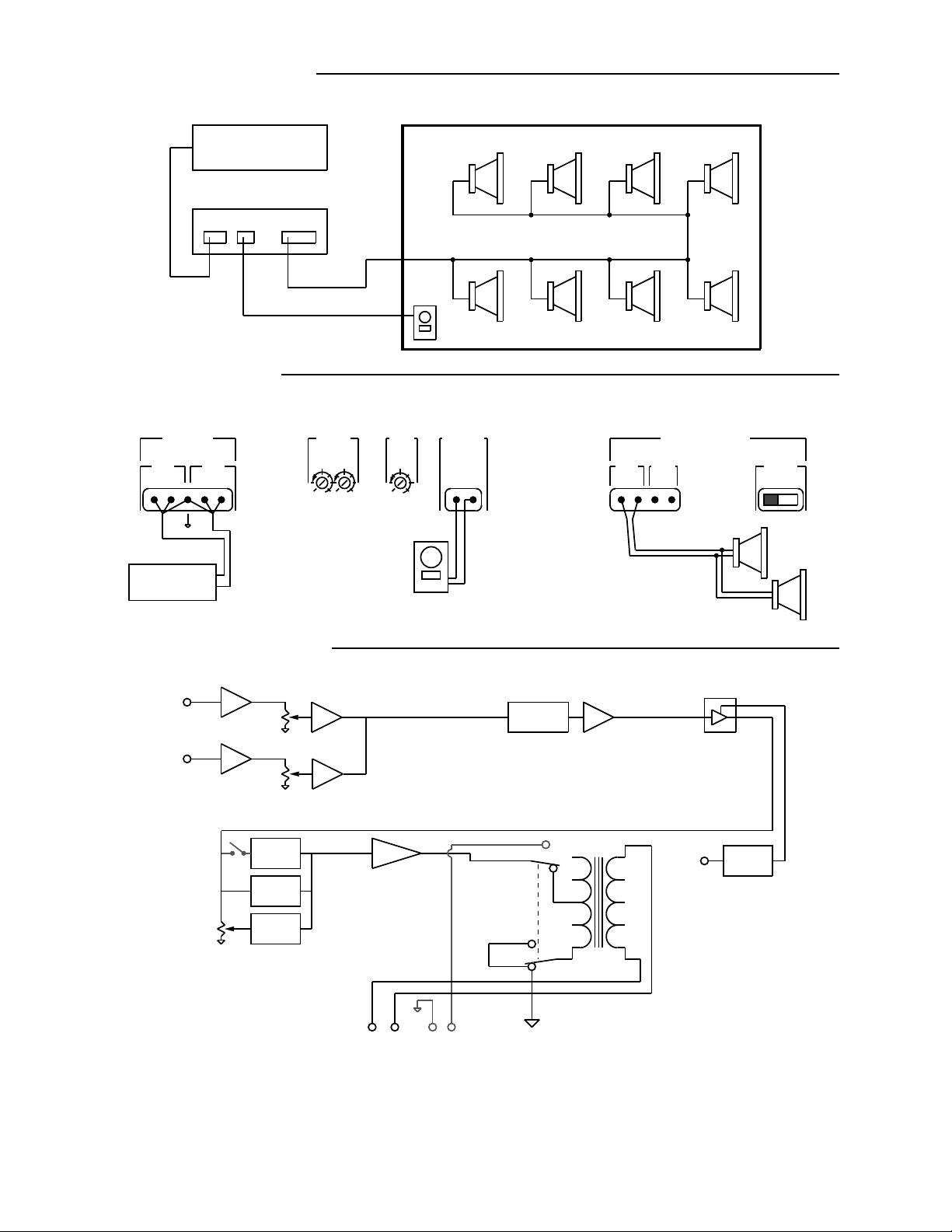
Example Listening Zone
Source
AmPlus™ 50
Rear Panel Hookup
Remote
Volume
Control
INPUTS A
Ch1
Ch2
+- +-
Source
L
R
AmPlus 50 Signal Flow
Ch. 1
Channel 1
Input
Channel 2
Input
Bass
Gain
High
Pass
Filter
Switch
Level
Ch. 2
Level
High Pass
Filter
Dynamic
EQ
Bass Boost
LEVEL
-6 -6
-10-10
0 0-40 dB -40 dB
Ch2Ch1
Internal Switch Settings:
High Pass Filter: OFF
BASS
GAIN
OFF +10
Remote
Volume
Control
Power Amp 1
REMOTE
VOLUME
70/100V
Amplifier
Mode
Switch
4-16
70/100V
EQ Card
4-16
POWER AMPLIFIER
70/100V 4-16
+-+-
Tap settings:
less than or
equal to 50W
Remote
VCA
VCA
Control
MODE
70/100V 4-16
Power
Amplifier
Outputs
+ -
70/100V
+ -
4-16
Figure 9. AmPlus 50 Simple Mono Installation
36
Page 37

PART LIST NOTES
Notes: 1. This part is not normally available from Customer Service. Approval from the Field
Service Manager is required before ordering.
2. The individual parts located on the PCB are listed in the part list.
3. This part is critical for safety purposes. Failure to use a substitute
replacement with the same safety characteristics as the recommended
replacement may create shock, fire, and/or other hazards.
4. Not used on AmPlus™ 50 amplifier.
5. Used on 120V units only.
6. Used on 240V units only.
37
Page 38

MAIN PART LIST
AmPlus™ 100 Amplifier (see Figure 10)
Item
Number
1 SCREW, 6-32 X .5, MACH, FLAT, XREC 190623-008 5
2 COVER TOP, AMP 187966 1
3 TRANSFORMER, AUDIO, 70/100V 188600-001 1
4 CLIP, HEATSINK, BRIDGE RECT. 188568 1
5 NUT, 8-32 HEX W/LKWSHR 100413-2 7
6 CLIP, HEATSINK 188599 2
7 TRANSFORMER, POWER 187985 1
8 PCB ASSY, AMPLUS 100,
120V
240V
9 SCR, MACH, 8-32X 1/4, XREC, DRILK 179096-04 6
10 CLIP, HEATSINK 188598 6
11 INSUL. THERMAL COND, TO-220 188642-001 4
12 SCREW, MACH, #10-32, PAN, XREC 177637-44 4
13 INSUL. THERMAL COND., MULTIWATT 188642-002 2
14 HEATSINK, AMPLUS 50/100 187969 2
15 CONN ASSY, IEC RECEPT, AMPLUS 190621-001 1
16 CHASSIS, BASE, AMPLUS 100
120V
240V
17 SWITCH ASSY, DPST, NEON,
120V
240V
18 HARNESS ASSY, OPTION, 8 COND 188570 2
- HARNESS ASSY, 12 CONDUCTOR,
MAIN PCB TO AMP MODULE
Description Part Number Qty. Notes
187917-001
187917-002
187963-001
187963-002
190622-001
190622-002
188571-001 2
3
1
1
1
1
1
1 3
1, 2
1, 2
3
38
Page 39

(5 PLACES)
1
2
3
(4 PLACES)
12
14
(7 PLACES)
7
11
5
10
(4 PLACES)
4
6
8
(6 PLACES)
9
(2 PLACES)
13
15
16
17
(2 PLACES)
18
Figure 10. AmPlus™ 100 Amplifier Exploded View
39
Page 40

MAIN PART LIST
AmPlus™ 50 Amplifier (see Figure 11)
Item
Number
1 SCREW, 6-32 X .5, MACH, FLAT, XREC 190623-008 5
2 COVER TOP, AMP 187966 1
3 TRANSFORMER, 70/100V, AUDIO 188600-001 1
4 CLIP, HEATSINK, BRIDGE RECT. 188568 1
5 NUT, 8-32 HEX W/LKWSHR 100413-2 7
6 CLIP, HEATSINK 188599 2
7 TRANSFORMER, POWER 187985 1
8 PCB ASSY, AMPLUS 50,
120V
240V
9 SCR, MACH, 8-32X 1/4, XREC, DRILK 179096-04 6
10 CLIP, HEATSINK 188598 3
11 INSUL. THERMAL COND, TO-220 188642-001 2
12 SCREW, MACH, #10-32, PAN, XREC 177637-44 2
13 HEATSINK, AMPLUS 50/100 187969 1
14 INSUL. THERMAL COND., MULTIWATT 188642-002 1
15 CONN ASSY, IEC RECEPT, AMPLUS 190621-001 1
16 BASE, CHASSIS, AMPLUS 50,
120V
240V
17 SWITCH ASSY, DPST, NEON,
120V
240V
- HARNESS ASSY, 12 CONDUCTOR,
MAIN PCB TO AMP MODULE
Description Part Number Qty. Notes
187923-001
187923-002
183056-001
183056-002
190622-001
190622-002
188571-001 1
3
1
1
1
1
1
1 3
1, 2
1, 2
3
40
Page 41

(5 PLACES)
1
2
3
(7 PLACES)
(2 PLACES)
5
4
6
7
8
(6 PLACES)
9
(3 PLACES)
(2 PLACES)
10
11
12
13
14
15
16
17
Figure 11. AmPlus™ 50 Amplifier Exploded View
41
Page 42

ELECTRICAL PART LIST
Resistors
Reference Designator Description Part Number Notes
R1, 2, 3, 4, 5 POT, RTY, 20K, RIGHT
ANGLE, LOG TAPER
R100, 102, 110, 116, 193, 194, 312,
342, 412, 502, 503, 506, 507, 512,
514, 517, 520, 521, 524, 537, 538,
547, 549, 561, 563, 607, 711, 713
R101, 103, 111, 117, 606 9.09KΩ, 0805, 1/10W, 1% 133625-9091
R104, 105, 112, 118, 121, 171, 180,
181, 200, 201, 213, 214, 217, 219,
220, 221, 236, 237, 304, 311, 313,
330, 335, 341, 343, 370, 372, 505,
510, 519, 526, 560, 564, 567, 569,
600, 601, 705, 706, 708, 709
R106, 115, 182, 183, 184, 185, 186,
187, 188, 189, 202, 223, 235, 245,
246, 247, 401, 408
R113, 130, 133, 181, 190, 192, 213,
214, 219, 237, 244, 328, 369, 391, 604
R120, 170, 171, 210, 211, 212, 215,
216, 218, 300, 331, 357
R126, 131, 132, 141, 142, 152, 153,
164, 302, 303, 317, 318, 333, 334,
347, 348, 500, 501, 509, 515, 516,
525, 536, 546, 608, 700, 701
R150, 154 1.54KΩ, 0805, 1/10W, 1% 133625-1541
R151, 155, 325, 352, 367, 379 14.0KΩ, 0805, 1/10W, 1% 133625-1402 4
R160, 161 3.01KΩ, 0805, 1/10W, 1% 133625-3011 4
R162, 163, 204, 205, 230, 231, 241,
242, 243, 244, 364, 365, 376, 377,
380, 387, 545, 565, 710
R171 10.0KΩ, 0805, 1/10W, 1% 133625-1002
R181, 213, 219, 237 JUMPER, CHIP, 0805 133627
R203, 222 2.00KΩ, 0805, 1/10W, 1% 133625-2001 4
R206, 207, 232, 233 499Ω, 0805, 1/10W, 1% 133625-4990
R234, 326, 327, 358, 359, 382 6.19KΩ, 0805, 1/10W, 1% 133625-6191 4
R301, 332 2.43KΩ, 0805, 1/10W, 1% 133625-2431 4
R305, 339, 410, 704 1MEGΩ, 0805, 1/10W, 5% 133626-1055 4
R306, 307, 337, 338, 504, 518, 535,
543, 702, 703, 712, 714, 715, 717
R308, 340 5.62KΩ, 0805, 1/10W, 1% 133625-5621 4
R310, 316, 336, 345, 362, 371, 373 4.99KΩ, 0805, 1/10W, 1% 133625-4991 4
R314, 344 8.25KΩ, 0805, 1/10W, 1% 133625-8251 4
R315, 346 301KΩ, 0805, 1/10W, 1% 133625-3013 4
R319, 350 25.5KΩ, 0805, 1/10W, 1% 133625-2552 4
R320, 349, 356, 363, 374, 385 26.7KΩ, 0805, 1/10W, 1% 133625-2672 4
R321, 354 4.64KΩ, 0805, 1/10W, 1% 133625-4641 4
R322, 355, 511, 523, 539, 550 6.81KΩ, 0805, 1/10W, 1% 133625-6811 4
R323, 351 4.22KΩ, 0805, 1/10W, 1% 133625-4221 4
R324, 353 6.49KΩ, 0805, 1/10W, 1% 133625-6491 4
R328, 360, 369, 391, 407, 604 JUMPER, CHIP, 0805 133627 4,
1.00KΩ, 0805, 1/10W, 1% 133625-1001 4
10.0KΩ, 0805, 1/10W, 1% 133625-1002 4
100Ω, 0805, 1/10W, 1% 133625-1000 4
JUMPER, CHIP, 0805 133627 AmPlus
47.5KΩ, 0805, 1/10W, 1% 33625-4752 4
100KΩ, 0805, 1/10W, 1% 133625-1003 4
30.1KΩ, 0805, 1/10W, 1% 133625-3012 4
20.0KΩ, 0805, 1/10W, 1% 133625-2002 4
187484-001 4
50
AmPlus
100
42
Page 43

ELECTRICAL PART LIST
Resistors (continued)
Reference Designator Description Part Number Notes
R366, 378 40.2KΩ, 0805, 1% 133625-4022 4
R381, 386 4.02KΩ, 0805, 1/10W, 1% 133625-4021 4
R400, 409 301Ω, 0805, 1/10W, 1% 133625-3010 4
R402, 403 402Ω, 0805, 1% 133625-4020 4
R411 3.32KΩ, 0805, 1/10W, 1% 133625-3321 4
R414, 415, 541, 571 10Ω, 2512, 1W, 5% 181895-10R0 4
R508, 522, 540, 548 220Ω, 2512, 1W, 5% 181895-2200 4
R527, 529, 532, 533 2.49KΩ, 0805, 1/10W, 1% 133625-2491 4
R528, 530, 531, 534 49.9KΩ, 0805, 1/10W, 1% 133625-4992 4
R568, 570 5.90KΩ, 0805, 1/10W, 1% 133625-5901 4
R602, 603 .75Ω, 1210, 1/4W, 5% 180956-R75E
3
Capacitors
Reference Designator Description Part Number Notes
C1, 2 1000pF, Y-Cap, Rifa P/N:
PME290MA4100M
C100, 103, 111, 116 680pF, 0805, COG, 50V, 5% 133622-681
C104, 105, 107, 112, 114, 117,
160, 163, 180, 255, 315, 332
C106, 108, 113, 118, 130, 131,
140, 141, 151, 153, 161, 162, 198,
199, 216, 217, 240, 241, 244, 245,
249, 251, 252, 253, 254, 301, 304,
305, 313, 314, 316, 317, 321, 322,
330, 331, 337, 341, 347, 408, 409,
521, 526, 532, 533, 534, 535, 602,
603, 604, 605, 608, 609, 614, 615,
616, 617, 618, 619, 620, 701, 702,
703, 705, 706
C120, 170, 333, 707 4.7uF, EL, 105, 35V, 20% 137126-4R7 4
C150, 152, 302, 303, 308, 319,
320, 325, 500, 501, 503, 505, 506,
510, 511, 513, 514, 516, 518, 522,
523, 527, 528, 529, 612, 613, 700
C201, 202, 230, 231, 400, 402,
403, 407
C210, 212, 214, 219, 242, 243,
246, 247, 530, 531, 704
C211, 213, 215, 218, 318, 360 1.0uF, EL, 105, 50V, 20% 137126-1R0 4
C197, 248, 250, 504, 508, 509,
512, 515, 517, 519, 525
C307, 324 1800PF, 0805, COG, 50V, 5% 133622-182 4
C309, 329 .068uF, BOX, 85, 63V, 5% 137127-683 4
C310, 312, 327, 328, 339, 342 .15uF, BOX, 85, 50V, 5% 137127-154 4
C311, 326 .1uF, BOX, 85, 50V, 5% 137127-104 4
C334, 335, 340 .22uF, BOX, 85, 50V, 5% 137127-224
47pF, 0805, COG, 50V, 5% 133622-470 4
.10uF, 0805, Y5V, 25V, 80% 133624 4
10UF, EL, 105, 35v, 20% 149948-100V 4
560pF, 0805, COG, 50V, 5% 133622-561 4
100pF, 0805, COG, 50V, 5% 133622-101 4
1000pF, 0805, COG, 50V, 5% 133622-102 4
170183
3
43
Page 44

ELECTRICAL PART LIST
Capacitors (continued)
Reference Designator Description Part Number Notes
C336, 344, 345, 346 .033uF, BOX, 85, 63V, 5% 137127-333 4
C338, 343 .12uF, BOX, 85, 50V, 5% 137127-124 4
C401, 405, 502, 507, 520, 524 .01uF, 0805, X7R, 50V, 5% 133623-1035 4
C406 .033uF, 0805, X7R, 50V, 10% 133623-333
C606, 607 4700UF, EL, BP, 105, 50V,
20%
C610, 611 4700UF, EL, 105, 50V, 20% 144000-472E
Diodes
Reference Designator Description Part Number Note
B600, B601 RECT, BRIDGE, 100V, 6A 170214 3
187394
D200, 201, 202, 203, 300, 306,
511, 515, 603, 700, 701, 702
D301, 305 SOT-23, BAV70 147249 4
D302, 304, 506, 514, 703 BAV99, SOT23 147239 4
D401, 402, 500, 504, 508, 512 ZENER, 5%, 9.1V, SOT-23 148333 4
D501, 503, 507, 510 1N4531, 5MM 136603 4
D502, 505, 509, 513, 600, 601 RECT, 1.5A, S2A 187479-001 4
Reference Designator Description Part Number Note
Q201, 221, 300, 304, 400, 402,
600, 601, 701
Q301, 302, 305, 306, 700 PNP, SOT, MMBT3906 148596 4
Q401, 403 JFET, TO-92 188634-001 4
Q500, 504, 506, 510 BPLR, N, 60V, 200MA, TO-92 117921 4
Q501, 503, 507, 509 BPLR, P, 60V, 200MA, TO-92 119168 4
Q502, 508 DARL, P, TIP146T 172285 4
Q505, 511 DARL, N, TIP141T 172284 4
SOT, MMBD914LT1 148582 4
Transistors
NPN, SOT, MMBT3904 146819 4
44
Page 45

ELECTRICAL PART LIST
Integrated Circuits
Reference Designator Description Part Number Note
U100, 106, 201, 202, 203, 306,
700
U101, 200, 300, 301 0P AMP QUAD, SOIC-14,
U102, 103, 104, 105, 304, 305 OP AMP SWTCH, SOIC-8,
U204 Q-TRANSCOND, SO-16,
U302, 303 OP AMP, SNGL, SO-8,
U500, 501 POWER AMP, AUDIO,
U502, 503, 701 COMPARATOR, SOIC-8,
U600 VOLT REG, 12V, 1A, POS,
U601 VOLT REG, 12V, 1A, NEG,
OP AMP DUAL, SOIC-8,
NJM4559
NJM2059
NJM2120
SSM2164S
CA3080
TDA7294
NJM311M
T0-220, LM 7812
T0-220, LM 7912
187473 4
187472 4
187474 4
187476
187617-001 4
170156 4
187477 4
116736
149009-12
Miscellaneous
Reference Designator Description Part Number Note
F600, 601, 602 FUSE, 4.0A, SLO BLO 177311-04000
3, 5
F600, 601, 602 FUSE, 3.15A, SLO BLO 177311-03150
3, 6
FC600A, 600B, 601A,601B, 602A,
602B
J1, 5 CONN, RT ANGLE, BEAU 177291-05 4
J12 CONN, HEADER, 5 POS 148591-05
J2, 3 CONN, HEADER, 8 POS 148591-08 4
J4 CONN, RT ANGLE, BEAU 177291-03 4
J400 CONN, HEADER, 3 POS 143965
J401 CONN, HEADER, 5.0MM,
J405, 407, 410, 501, 502, 605, 606 RES, JUMPER, 0Ω 139942 4, 5
J405, 407, 409, 410, 501, 502, 603 RES, JUMPER, 0Ω 139942 4, 6
J403, 404, 406, 410, 501, 605, 606 RES, JUMPER, 0Ω 139942 5
J403, 404, 406, 409, 501, 603 RES, JUMPER, 0Ω 139942 6
J6 CONN, SHIELDED,
J6 (mate to female connector above) CONN, SHIELDED,
J6 CONN, SHIELDED,
J6 (mate to female connector above) CONN, SHIELDED,
(used with male connector above) LEVER, OPERATING, J6
FUSECLIP, 5MM 178548
191946-004
5A
190693-008 4
FEMALE, 8 PIN
190694-008 4
MALE, 8 PIN
190693-004
FEMALE, 8 PIN
190694-004
MALE, 8 PIN
193501
CONNECTOR
45
Page 46

ELECTRICAL PART LIST
Miscellaneous (continued)
Reference Designator Description Part Number Note
J600 CONN, HEADER, 2 POS 143963
J601 HEADER, HIGH
CURRENT, 8MM PITCH
J602 CONN, HEADER, INLINE,
PCB MNT, 5P
J7, 7B, 8, 8B CONN, HEADER, 12
POS, MALE
J9, 10 CONN, HEADER,
SHIELDED, 12 POS
K600 RELAY, 12V, DPST, 8A 191928
S1 SWITCH, SP, 3 POS,
VERT, SLIDE
S4, 5, 7 SWITCH, SPDT,
VERTICAL, SLIDE
S6 SWITCH, DPDT, 5A,
RIGHT ANGLE, SLIDE
VR600 VARISTOR, METAL
OXIDE, 275V, 75 JOULE
178742-5
133220-05
137489-12 4
170250 4
187482 4
187481 4
187480
170189
3
3
3
3
3
46
Page 47

AMPLUS™ 50 AND 100 ACCESSORY NOTES
1. The AmPlus 50 and 100 Business Music Amplifiers MUST be used with the Power Amplifier
Accessory Kits referred to in Figure 12. These kits supply the necessary parts to allow the
amplifiers to be used in different countries. They include the literature kit, power cord, and
remote volume control required for that voltage and configuration. The amplifiers themselves
are also configured internally for use at 120 or 240 Volts.
2. The AmPlus 50 and 100 Amplifiers can be rack mounted using the optional rack-mount kit.
Refer to Figure 16 for more information.
3. The AmPlus 100 Amplifier can use the optional Opti-Source™ and Opti-Voice
®
Page Option
Cards to extend the abilities of the amplifier in different installations. These Option Cards will
be covered more extensively in the supplement to this service manual (part number
194101-S1).
4. The AmPlus 100 Amplifier can be used with the optional CVT-100 Transformer Accessory
Kit to allow 70/100V operation in both channels. Refer to Figure 15 for more information.
5. The AmPlus 50 and 100 Amplifiers can be used with optional Equalizer Cards to allow the
®
use of the Free Space
Model 1B Acoustimass® Module, and the Model 8, Model 25, and
Model 32 Loudspeakers.
Table 14. AmPlus 50 and 100 Amplifiers and Accessories
Item Description Product Code Part Number
Power Amplifiers
AmPlus 100
120Vac
240Vac
017803
017804
187915-001
187915-002
Amplus 50
120Vac
240Vac
017805
017806
187921-001
187921-002
Power Amplifier Accessory Kits
US/Canada
Europe
Japan
U.K.
Australia
017989
017990
017991
017992
017993
187492-001
187492-002
187492-003
187492-004
187492-005
Rack Mount kit 019596 191909-001
Opti-Voice page option card 019073 187515-001
Opti-Source option card 019074 187505-001
CVT-100 Transformer accy kit 020743 193541-001
Model 1B EQ card 019509 190670-001
Model 8 EQ card 015134 184824-001
Model 32 (and Model 25) EQ card 011687 183744-001
47
Page 48

PACKING LIST
Power Amplifier Accessory Kit (see Figure 12)
Item
Number
1 Carton, D/C, Accessory 177798 1
2 Feet, Chassis, kit, (4 feet) 187478 1
3 Sheet, Instruction, AmPlus™
4 Line Cord, Detachable
US/Canada, 120V
Europe, 220V
Japan, 100V
UK, 240V
Australia, 240V
5 System Assy, Remote, BMS, Volume,
US/Canada
Europe
Japan
UK
Australia
6 Connector Kit, AmPlus 50,
AmPlus 100 188620-001 1
Description Part Number Qty. per
187957 1
173350
173352
181690
173351
173354
187491-1
187491-2
187491-3
187491-4
187491-5
1
Assy
1
1
1
1
1
1
1
1
1
1
6
2
3
5
4
Figure 12. Accessory Kit Packing Diagram
48
Page 49

PART LIST
Remote Volume Control (see Figure 13)
Item
Number
Description Part
Number
1 PCB Assy, Rem, BMS, Volume 187983
2 Wallplate, RVC, (US, CA, AUS) 188611
2 Wallplate, No Switch, RVC, (EURO, UK) 188610
2
Cover, Remote, FreeSpace® 6 (Japan)
3 Knob, Remote, FreeSpace 6 (All Models) 178104
4 Screw, Mach, 6-32x1, .00, ovalhd (US/CA) 178115-16
4 Screw, Mach, M3, 5x25mm, Flat, XREC (EURO,
178116-25
UK, AUS, JAPAN)
5 Screw, Tapp, 6-13x.5, PAN, XREC 173555-08
6 Bag, Poly, 9.38x6x2 mil 100278
7 Carton, D/C, Interlock Kit, Cann 131843
4
3
2
178102
7
1
5
6
Figure 13. Remote Volume Control Exploded View
49
Page 50

PACKING LIST
AmPlus™ 50 and 100 Amplifier (see Figure 14)
Item
Description Part Number Quantity
Number
1 LIT KIT, AMPLUS 50/100, contains:
BROCHURE, ALL PRODUCTS
OWNER’S MANUAL
DECLARATION OF CONFORMITY
REGISTRATION CARD
191954
188898
190652
188657
180089
2 BAG, POLY, 15X28X4 MIL 187487-028 1
3 PACKING, CORNER BLOCK, EPP 187486 2
4 CARTON, AMPLUS, RSC 187489 1
2
1
1
1
1
1
3
ASSEMBLED
AMPLIFIER
4
Figure 14. AmPlus Series Amplifier Packing Diagram
50
Page 51

PART LIST
AmPlus™ 100 Amplifier Accessory Transformer (see Figure 15)
Item
Description Part Number Qty. per
Number
1 Autotransformer, Accy, 70/100V 193502 1
2 Enclosure, Top, Trans. 190662 1
3 Enclosure, Bottom, Trans 190661 1
4 Screw, Tapp, 4-24, Pan Head 190118-06 2
5 Screw, #8-32, Pan Head 190623-008 8
6 Nut, Hex, 8-32, Keps 100413-2 2
7 Carton Vendor Supplied 1
8 Manual, Owner's 193542 1
9 Poly Bag Vendor Supplied 1
10 Lever, Operating 193501 1
11 Connector, Male, sheilded 190694 1
4
2
Assy.
5
6
1
3
8
10
11
9
7
Figure 15. AmPlus 100 Accessory Transformer Exploded and Packing View
51
Page 52

PART LIST
AmPlus™ 50 and 100 Amplifier Rack Mount Accessory Kit (see Figure 16)
Item Number Description Part Number Qty.
1 Bracket, Rack Mount 187962 2
2 Tube, Packing, with end caps 184177 1
3 Poly Bag vendor supplied 2
4 Instruction Sheet 191958 1
END CAP
2
4
3
1
2
Figure 16. AmPlus 50 and 100 Amplifier Rack Mount Accessory Kit
52
Page 53

DEVICE PIN-OUT DIAGRAMS
IC, Volt Reg,
12V, Pos,
TO-220
Pin 1. Input
Pin 2. Ground
Pin 3. Output
BCE
BOTTOM VIEW
123
Bose® P/N: 116736, LM 7812
BCE
BOTTOM VIEW
BCE
FRONT VIEW
FRONT VIEW
Bose P/N: 117921, 2SC536
3
1 2
BCE
PIN FUNCTION
1. BASE
2. EMITTER
3. COLLECTOR
Bose P/N: 119168, 2SA608 Bose P/N: 146819, MMBT3904
3
1 2
PIN FUNCTION
1. ANODE
2. ANODE
3. CATHODE
3
1 2
PIN FUNCTION
1. ANODE
2. ANODE
3. CATHODE
Bose P/N: 147239, BAV99 Bose P/N: 147249, BAV70
53
Page 54

DEVICE PIN-OUT DIAGRAMS
3
PIN FUNCTION
1. ANODE
2. NO CONNECTION
1 2
3. CATHODE
Bose® P/N: 148333, ZENER, 9.1V, SOT-23
3
PIN FUNCTION
1. BASE
2. EMITTER
1 2
3. COLLECTOR
3
PIN FUNCTION
1. ANODE
2. NO CONNECTION
1 2
3. CATHODE
Bose P/N: 148582, MMBD914LT1
IC, Volt Reg,
12V, Neg,
TO-220
Pin 1. Ground
Pin 2. Input
Pin 3. Output
Bose P/N: 148596, MMBT3906
+-
Bose P/N: 170214, GBU6 Rectifier
123
Bose P/N: 149009-12, LM 7912
PIN 1. BASE
PIN 2. COLLECTOR
PIN 3. EMITTER
123
Bose P/N: 172284, TIP141T
54
Page 55
DEVICE PIN-OUT DIAGRAMS
1
PIN 1. BASE
PIN 2. COLLECTOR
PIN 3. EMITTER
2
-+
3
4
5
-+
6
7 8
123
Bose® P/N: 172285, TIP146T Bose P/N: 187472, NJM2059M
1
2
3
A
-+
B
8
7
-+
6
PIN FUNCTION
1. A OUTPUT
2. A -INPUT
3. A +INPUT
4. V-
5. B +INPUT
45
6. B -INPUT
7. B OUTPUT
8. V+
1
2
-+ +-
3
4 5
-+
-+
14
13
12
11
10
9
8
7
6
PIN FUNCTION
1. A OUTPUT
2. A -INPUT
3. A +INPUT
4. V+
5. B +INPUT
6. B -INPUT
7. B OUTPUT
8. C OUTPUT
9. C -INPUT
10. C +INPUT
11. V-
12. D +INPUT
13. D -INPUT
14. D OUTPUT
PIN
FUNCTION
1. SWITCH
CONTROL
2. A +INPUT
3. A -INPUT
4. V-
5. OUTPUT
6. B -INPUT
7. B +INPUT
8. V+
Bose P/N: 187473, JRC NJM4559M
VC
I-IN
VC
I-IN
VC
I-IN
VC
I-IN
VCA1
VCA2
VCA3
VCA4
POWER SUPPLY AND
BIASING CIRCUITRY
V+ GND
V- MODE
I-OUT
I-OUT
I-OUT
I-OUT
Bose P/N: 187476, SSM2162S
Bose P/N: 187474, NJM2120M
1
2
3
4
5
6
7
89
16
15
14
13
12
11
10
PIN CONFIGURATION
1. MODE
2. I IN1
3. VC1
4. I OUT1
5. I OUT2
6. VC2
7. I IN2
8. GND
9. V-
10. I IN3
11. VC3
12. I OUT3
13. I OUT4
14. VC4
15. I IN4
16. V+
55
Page 56

DEVICE PIN-OUT DIAGRAMS
Pin function
1
2
3
4 5
8
7
6
Bose® P/N: 187477, NJM311M Bose P/N: 187479-001 S2A SMD Diode
1. Gnd
2. + Input
3. - Input
4. V-
5. Bal
6. Bal/Strobe
7. Output
8. V+
CATHODE
ANODE
BCE
NC
INV. INPUT
NON-INV.
INPUT
V-
1
2
3
4
-
+
8
NC
7
V+
6
OUTPUT
AMPLIFIER
5
BIAS INPUT
BOTTOM VIEW
BCE
FRONT VIEW
Bose P/N: 188634-001, J107Bose P/N: 187617, CA3080
56
Page 57

DEVICE PIN-OUT DIAGRAMS
Pin Function
15
14
13
12
11
10
9
8
7
6
5
4
3
2
1
TOP-VIEW
15. -Vs (Power)
14. OUT
13. +Vs (Power)
12. N.C.
11. N.C.
10. MUTE
9. STAND-BY
8. -VS (Signal)
7. +VS (Signal)
6. Bootstrap
5. N.C.
4. SVR
3. Non-Inverting Input
2. Inverting Input
1. Stand-by Gnd.
IN-
IN+
IN+MUTE
MUTE
STANDBY
2
3
4
10
9
TDA7294
MUTE
STANDBY
STANDY
GROUND
+Vs (signal)
-
+
-Vs (signal)
7
81
THERMAL
SHUTDOWN
+Vs (power)
13
SHORT-
CIRCUIT
PROTECTION
15
-Vs (power)
14
6
OUT
BOOT-
STRAP
Bose® P/N: 170156, TDA7294
57
Page 58

TROUBLESHOOTING TIPS
F
1. General Troubleshooting Procedures
1.1 These units are very flexible in regard to setup and operation, which means that it will be
much easier for the customer to install and/or setup the unit incorrectly. Be sure to check that
the product was installed properly, and that all switches are in the correct positions for that
particular usage. Refer to the AmPlus™ 50 and 100 Installation diagrams and the Amplifier
Controls pages for more information.
1.2 The main circuit board is built with the surface-mounted IC's mounted on the underside of
the board. There are several test-points located on the top of the PCB which are easier to
access than the devices themselves, which can be used to troubleshoot down to a smaller
area before probing on the bottom of the board is necessary. Refer to the appropriate
schematic diagram, and look for the diamond shape near the signal paths. These points
are silk-screened on the top of the PCB and labelled as TS2, TS3, etc. Refer to the PCB layout
diagrams for more information.
1.3 If you need to operate the unit with the PCB in the upright position, you must connect a
ground wire from the unit chassis to one of the ground points on the PCB for proper operation.
2. Hum and noise problems
2.1 If the customer is experiencing hum and/or noise problems, check to make sure the
following installation guidelines were met.
• Connect high impedance units, such as tape players and CD players, to the amplifier
with shielded, single conductor cable. Keep cable lengths less than
10 feet (3 meters).
• Use twisted shielded pairs on microphone inputs.
• Keep input cables away from:
-Loudspeaker cables to prevent inductive feedback.
-Power lines or transformers.
• For output loudspeaker connections, Class II wiring is suggested. Use standard
#16 AWG wire. Keep loudspeaker cables away from power cables.
58
Page 59

AmPlus™ 50 and AmPlus 100
Business Music Amplifiers
®
®
©
1997 Bose Corporation
Service Manual
Part Number 194101 Rev. 00
Page 60

SPECIFICATIONS AND FEATURES SUBJECT TO CHANGE WITHOUT NOTICE
®
®
Bose Corporation
The Mountain
Framingham, Massachusetts USA 01701
P/N: 194101 Rev.00 11/97 FOR TECHNICAL ASSISTANCE OR PARTS ORDERS, CALL 1-800-367-4008
 Loading...