

Page 1
Bose® 802
®
Series III Loudspeaker
©2007 Bose Corporation
Service Manual
Part Number 260432 REV. 02
Page 2

Contents
Specifications ....................................................................................................................................2
Disassembly/Assembly Procedures ........................................................................................... 3-4
Figure 1. Schematic Diagram ..............................................................................................................4
Figure 2. Wiring Diagram ..................................................................................................................... 4
Figure 3. Driver Location Diagram....................................................................................................... 4
Test Procedures ................................................................................................................................5
Main Part List..................................................................................................................................... 6
Figure 4. Exploded View ......................................................................................................................6
Shading Network Part List ............................................................................................................... 7
Figure 5. Shading Network Layout ......................................................................................................7
Packaging Part List ...........................................................................................................................7
Figure 6. Packaging View .................................................................................................................... 7
WARRANTY: 5 year limited warranty
PROPRIETARY INFORMATION
THIS DOCUMENT CONTAINS PROPRIETARY INFORMATION
OF BOSE® CORPORATION WHICH IS BEING FURNISHED
ONLY FOR THE PURPOSE OF SERVICING THE IDENTIFIED
BOSE PRODUCT BY AN AUTHORIZED BOSE SERVICE
CENTER OR OWNER OF THE BOSE PRODUCT, AND SHALL
NOT BE REPRODUCED OR USED FOR ANY OTHER PURPOSE.
SPECIFICATIONS
External dimensions:
Single speaker: 13.5" H x 20.5" W x 13.0" D (34.3 x 52.1 x 33.0)cm
Packed system: 14.4" H x 21.8" W x 18.3" D (36.6 x 55.4 x 46.4)cm
Weight:
Single speaker: 29.3 lbs (13.29 kg)
Packed system: 32 lbs (14.5 kg)
Transducer:
Internal cabinet volume:
Port:
Type: Two round ports located central to each four speaker pattern.
Total port area: 6.0 sq. in. (38.9 sq. cm)
Port length: 7.5" (19.0 cm)
Resonance frequency: 50 Hz
Impedance:
Power handling:
Eight 4.5" environmental drivers per enclosure
3,020.7 cu. In. (49.5 liters)
8 ± 2 Ohm
240W continuous per IEC-268-5
Sensitivity:
91 dB SPL, 1W, 1m
2
Page 3
DISASSEMBLY/ASSEMBLY PROCEDURES
Note: Numbers in parenthesis correspond to
call-outs in figure 4.
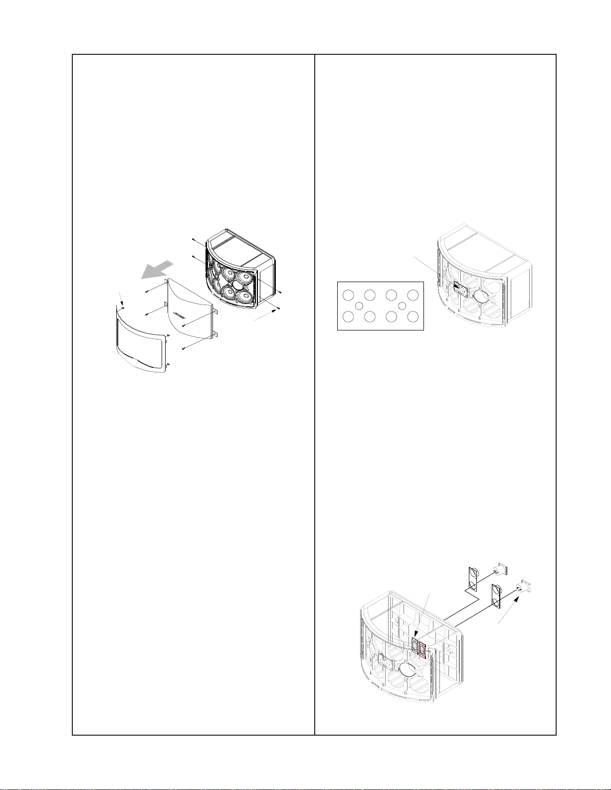
1. Grille Removal
1.1 Remove the four screws (16) securing
the trim ring (8) to the cabinet. Pull off the trim
ring leaving the four clips (17) in place on the
cabinet.
1.2 Remove the four screws (10) securing the
grille (6) to the cabinet. Pull off the grille.
Clips stay
in cabinet
Secures
trim ring
4.2 Line up the driver and gasket (2) to the
cabinet and secure it with three screws (10).
5. Shading Network PCB Removal/Access
5.1 Remove the position 2, 3, 6, and 7 drivers
(1) from the cabinet using procedure 3.1-3.2.
5.2 Using a short flat-blade screwdriver,
remove the two screws securing the shading
network PCB (3) to the inside wall of the
cabinet. Remove wires as needed.
Shading network PCB
located inside
front wall
Top of speaker
4
32
8
7
Driver location
1
6
5
2. Grille Replacement
2.1 Line up the grille (6) with the cabinet and
secure it with four screws (10).
2.2 Line up the trim ring (8) with the cabinet.
Press the trim ring into the four clips (17)
located in the corners of the cabinet.
2.3 Replace the four screws (16) securing the
trim ring to the cabinet.
3. Driver Removal
3.1 Perform procedure 1.
3.2 Remove the three screws (10) securing
the driver (1) to the cabinet. Lift out the driver.
3.3 Cut the wires as close as possible to the
driver’s wire terminal.
6. Shading Network PCB Replacement
6.1 Referring to figure 2, replace any wires
that were removed.
6.2 Replace the two screws securing the
shading network PCB (3)
7. Speakon Connector Removal
7.1 Perform procedure 3.1-3.2 to remove the
position 2, 3, 6, and 7 drivers.
7.2 Using a flat-blade screwdriver, pry out the
tinnerman clip (5) securing the Speakon
connector (4) to the cabinet.
Tinnerman clips
located inside
on back wall
Speakon
connector
4. Driver Replacement
4.1 Referring to figures 1, 2, and 3, attach the
wires to the driver’s (1) wire terminal.
7.3 Pull out the Speakon connector and
remove the wires.
3
Page 4

DISASSEMBLY/ASSEMBLY PROCEDURES
+
_
+
_
+
_
+
_
+
_
+
_
+
_
+
_
3
26
7
415 8
PTC
C1
5 uF
C2
20 uF
RD
BK
OR
PU
BN
PK
BL WH
GN
YL
PK
GY
BLK
8. Speakon Connector Replacement
8.1 Referring to the figure 2, attach the wires to the Speakon connector (4).
8.2 Align the Speakon connector in the cabinet.
8.3 Reshape the tinnerman clip (5) or use a new one. Place an appropriate size wood block
between the Speakon connector (rear of speaker) and a hard surface. Using a flat-blade screwdriver (or similar tool) and a hammer, secure the tinnerman clip into place. Make sure the
Speakon connector is securely fastened.
RD
BK
+
2-
2+
3
_
+
OR
1+
1-
2-
REAR VIEW OF
NEUTRIK CONNECTORS
CROSSOVER BOARD_802
26
_
_
+
BN
BL
BL WH
C1
5 uF
C2
20 uF
GN
7
415 8
_
+
_
+
+
YL
BK
PTC
_
_
_
WH
+
+
GN
GY
Earlier Versions Later Versions
Figure 1. Schematic Diagram
YELLOW
GREY
WHITE
WHITE
+
-
DVR 8- (BLACK)
DVR 7- (GREEN)
DVR 3+ (RED)
DVR 1- (WHITE)
DVR 2- (BLUE)
1
-
5
+
1+
RED
BLACK
1-
2+
BLACK
RED
ORANGE
BROWN
BLUE
BLUE
RED
2
+
+
BLUE
GREEN
BLACK
ORANGE
-
6
-
BROWN
GREEN
3
+
YELLOW
+
4
7
+
8
-
+
GREEN
GREY
2-
2+
1+
REAR VIEW OF
NEUTRIK CONNECTORS
CROSSOVER BOARD_802
1+
1-
2-
2+
YELLOW
1-
WHITE
PINK
GREY
WHITE
+
-
BROWN
DVR 8- (BLACK)
DVR 7- (GREEN)
DVR 3+ (RED)
DVR 1- (WHITE)
DVR 2- (BLUE)
ORANGE
PURPLE
BLUE
1
-
5
+
PURPLE
RED
2
+
+
PINK
BROWN
ORANGE
3
+
PINK
-
GREEN
+
4
YELLOW
7
-
+
8
-
+
GREY
BLACK
6
Earlier Versions
Later Versions
Figure 2. Wiring Diagram
Top of speaker
4
8
Figure 3. Driver Location Diagram
4
32
7
6
1
5
Page 5

TEST PROCEDURES
1. Phase Test
1.1 Observing polarity, apply 9 VDC to the
input connector. Refer to the figure below.
1.2 All driver cones should move outward.
Referring to figure 1, rewire any driver that
moves inward.
1+
2-
1-
2+
Positive input
Negative input
2. Crossover Test
2.1 Connect a 0.5 Ohm resistor and amplifier
to the speaker input connector as shown in
the diagram below.
Amplifier
Speaker Output
-
+
Volt meter
-
0.5 Ohm
Speaker
+
+
-
3. Rub and Tick Test
3.1 Apply a 10 Vrms, 10 Hz signal to the
speaker input connector.
3.2 No extraneous noises such as rubbing,
scraping or ticking should be heard.
Note: To distinguish between normal suspension noise and rubs or ticks, slightly displace
the cone of the driver with your fingers. If the
noise can be made to go away or get worse, it
is a rub or tick and the driver should be
replaced. If the noise stays the same, it is
normal suspension noise and the driver is
fine. Suspension noises will not be heard with
program material.
4. Air Leak Test
4.1 Apply a 15 Vrms, 65 Hz signal to the
speaker input connector.
4.2 Listen for air leaks around the drivers and
cabinet seam. Reposition or replace any
gasket found to leak. Repairs made to the
cabinet seam should not be visible from the
exterior of the speaker.
5. Sweep Test
5.1 Apply a 10 Vrms, 10 Hz signal to the
speaker input connector.
2.2 Apply a 2 Vrms signal to the speaker input
connector at the frequencies listed in the table
below.
2.3 Measure the voltage across the 0.5 Ohm
resistor comparing the results to the table
below. If the voltage is out of range, check the
crossover components and wiring.
Frequency Min Max
8 kHz 104 mVrns 141 mVrms
12 kHz 77 mVrms 120 mVrms
5.2 Sweep the signal generator from 10 Hz to
500 Hz.
5.3 Apply a 500 Hz, 5 Vrms signal to the
speaker input connector.
5.4 Sweep the signal generator from 500 Hz
to 5 kHz.
5.5 Listen for buzzes, rattles or other noises.
Redress any wire that buzzes; replace any
driver that is found to be defective.
Note: A whooshing noise from the port at its
resonance frequency of 50 Hz is acceptable.
5
Page 6

MAIN PART LIST
Item
Number
Description Part
Qty. Note
Number
1 DRIVER, 4.5" 290722-001 8 1
2 GASKET, 4.5" 259111 8
3 NETWORK, SHADING 291189-001 1
4 CONN, SPEA KON, PANEL MOUNT 254423 2
5 CLIP, TINNERMAN 187943 2
6 GRILLE, BLACK
GRILLE, ARCTIC WHITE
GRILLE, PRO GRAY
7 NAMEPLATE, LOGO, BLACK
NAMEPLATE, LOGO, ARCTIC WHITE
8 RING TRIM, BLACK
RING TRIM, WHITE
256350-001
256350-002
256350-004
254457-001
254457-002
256349-001
256349-002
1
1
1
9 SCREW, THUMB, M8 x 1. 25 x 25mm 137050 2
10 SCREW, TAPP, 8-15, HEXW, SLOT 290290-12 30
11 COVER, NEUTRIK, SEALING 252384 2
12 CONN, FUSE CLIP, 1 POS, FEMALE 291366 2
13 NUT, J-TYPE, 8-32 109481 24
14 LATCH, SPRING 293290-001 4
15 CLIP, PUSH-ON, DIA .375 252379 2
16 SCREW, TAPP, 6-13 x. 5, PAN, XR 290294-08 4
17 CLIP, PUSH-ON, U-TYPE 290295-01 4
18 SCREW, TAPP, 6-20 x. 5, PAN, XR 290296-08 2
Note: When ordering a driver, also order a driver gasket.
12
18
x2
16
4
x2
x4
x2
5
x8
2
1
x30
10
3
6
x30
10
7
x4
17
8
x2
9
x2
15
13
11
x24
x4
14
Figure 4. Exploded View
6
Page 7

SHADING NETWORK PART LIST
Item
Number
1 20uF, FILM, 75V, 10% 119026 1
2 5.0uF, MYLAR, 100V, 10% 102770 1
3 POLYSWITCH, 50V, 31mm 175233-2 1
Description Part
Number
2
3
Figure 5. Shading Network Layout
Qty. Note
1
PACKAGING PART LIST
Item
Number
1 CARTON, RSC 256592 1
2 PACKING, PAD, DIE CUT 191669 2
3 PACKING, CORNER BLOCK 191668 4
4 MANUAL, OWNERS 256598 1
5 BAG, POLY, 23 x 44 x 10.5 x 1.25 100652 1
Description Part
Number
2
x2
4
3
x4
5
1
Qty. Note
Figure 6. Packaging View
7
Page 8

Date Revision
Description of Change Change Driven
Pages
SERVICE MANUAL REVISION HISTORY
Level
02/01 00 Document release revision
00
02/06 01 Added RoHS part numbers This product is
07/07 02 Added new schematic ECN 3
1
Service manual
compliant parts.
By
release
now built with
RoHS
Affected
All
5
8
Page 9

Specifications and Features Subject to Change Without Notice
Bose Corporation
The Mountain
Framingham Massachusetts USA 01701
P/N 260432 REV. 02 07/2007 (P) For Technical Assistance or Part Orders, Call 1-800-233-4408
http://serviceops.bose.com
 Loading...