

Page 1

The Bose
®
701 Direct/Reflecting
Series II Speakers
Owner’s Guide
October 25, 2001
AM257817_00_V.pdf
®
Page 2
CAUTIONCAUTION
RISK OF ELECTRICAL SHOCK
DO NOT OPEN
CAUTION: TO REDUCE THE RISK OF ELECTRIC SHOCK,
DO NOT REMOVE COVER (OR BACK).
NO USER-SERVICABLE PARTS INSIDE.
REFER SERVICING TO QUALIFIED PERSONNEL.
Important Safety Information
WARNING: To reduce the risk of fire or electric shock, do not expose the system to rain or
moisture.
These CAUTION marks are located on the back panel of your 701
®
speakers:
The lightning flash with arrowhead symbol, within an equilateral triangle, is
intended to alert the user to the presence of uninsulated dangerous voltage within
the system enclosure that may be of sufficient magnitude to constitute a risk of
electric shock.
The exclamation point within an equilateral triangle, as marked on the speakers,
is intended to alert the user to the presence of important operating and maintenance instructions in this owner’s guide.
CAUTION: To prevent electric shock, match wide blade of plug to wide slot, insert fully.
Note: This music system is not intended for use in moving vehicles.
WARNING: No naked flame sources, such as lighted candles, should be placed on the
apparatus.
Additional safety information
See the additional instructions on the additional Important Safety Information page enclosed
with this owner’s guide.
Please read this owner’s guide
Please take the time to follow this owner’s guide carefully. It will help you set up and operate
your 701 speakers properly. Save your owner’s guide for future reference.
©2001 Bose Corporation. No part of this work may be reproduced, modified, distributed, or otherwise
used without prior written permission. All trademarks referenced herein are the property of Bose Corpo-
2
ration.
Page 3

Contents
Setting Up . . . . . . . . . . . . . . . . . . . . . . . . . . . . . . . . . . . . . . . . . . . . . . . . . . . . . . . . . . . . . . . . . . . . 4
Introduction . . . . . . . . . . . . . . . . . . . . . . . . . . . . . . . . . . . . . . . . . . . . . . . . . . . . . . . . . . . . . . . . 4
Unpacking the speakers . . . . . . . . . . . . . . . . . . . . . . . . . . . . . . . . . . . . . . . . . . . . . . . . . . . . . . . 4
Attaching the speaker grilles. . . . . . . . . . . . . . . . . . . . . . . . . . . . . . . . . . . . . . . . . . . . . . . . . . . . 4
Placing the speakers . . . . . . . . . . . . . . . . . . . . . . . . . . . . . . . . . . . . . . . . . . . . . . . . . . . . . . . . . 5
Choosing the speaker cord . . . . . . . . . . . . . . . . . . . . . . . . . . . . . . . . . . . . . . . . . . . . . . . . . . . . 6
Making the connections . . . . . . . . . . . . . . . . . . . . . . . . . . . . . . . . . . . . . . . . . . . . . . . . . . . . . . . 6
Connecting to the receiver . . . . . . . . . . . . . . . . . . . . . . . . . . . . . . . . . . . . . . . . . . . . . . . . . . 6
Connecting the right accessory speaker to the left main speaker . . . . . . . . . . . . . . . . . . . . 7
Connecting the LFE subwoofer input . . . . . . . . . . . . . . . . . . . . . . . . . . . . . . . . . . . . . . . . . 8
Checking the connections . . . . . . . . . . . . . . . . . . . . . . . . . . . . . . . . . . . . . . . . . . . . . . . . . . 8
Plugging in the left main speaker . . . . . . . . . . . . . . . . . . . . . . . . . . . . . . . . . . . . . . . . . . . . . 8
Setting your non-digital receiver . . . . . . . . . . . . . . . . . . . . . . . . . . . . . . . . . . . . . . . . . . . . . 9
Setting your digital receiver . . . . . . . . . . . . . . . . . . . . . . . . . . . . . . . . . . . . . . . . . . . . . . . . . 9
Bass and LFE controls . . . . . . . . . . . . . . . . . . . . . . . . . . . . . . . . . . . . . . . . . . . . . . . . . . . . . . . . 9
Bass control . . . . . . . . . . . . . . . . . . . . . . . . . . . . . . . . . . . . . . . . . . . . . . . . . . . . . . . . . . . . . 9
LFE level control . . . . . . . . . . . . . . . . . . . . . . . . . . . . . . . . . . . . . . . . . . . . . . . . . . . . . . . . . 9
Reference Information . . . . . . . . . . . . . . . . . . . . . . . . . . . . . . . . . . . . . . . . . . . . . . . . . . . . . . . . . . . 10
Troubleshooting . . . . . . . . . . . . . . . . . . . . . . . . . . . . . . . . . . . . . . . . . . . . . . . . . . . . . . . . . . . . . 10
Technical Information . . . . . . . . . . . . . . . . . . . . . . . . . . . . . . . . . . . . . . . . . . . . . . . . . . . . . . . . . 11
Customer service . . . . . . . . . . . . . . . . . . . . . . . . . . . . . . . . . . . . . . . . . . . . . . . . . . . . . . . . . . . . 11
Cleaning . . . . . . . . . . . . . . . . . . . . . . . . . . . . . . . . . . . . . . . . . . . . . . . . . . . . . . . . . . . . . . . . . . . 11
Warranty
®
Bose
®
701
Direct/Reflecting
®
speakers are covered by a limited 5-year transferable warranty. The built-in amplifier and
electronic components are covered by a 1-year warranty. Details of the coverage are provided on the warranty card that
came with your speakers. Please fill out the information section on your card, detach, and mail to Bose.
For your records
The serial number is located on the label on the back of each speaker.
Serial numbers: __________________________ and _________________________________
Dealer name:___________________________________________________________________
Dealer phone: ____________________ Purchase date:_____________________________
We suggest you keep your sales slip and warranty card together with this owner’s guide.
AM257817_00_V.pdf October 25, 2001 3
Page 4
Setting Up
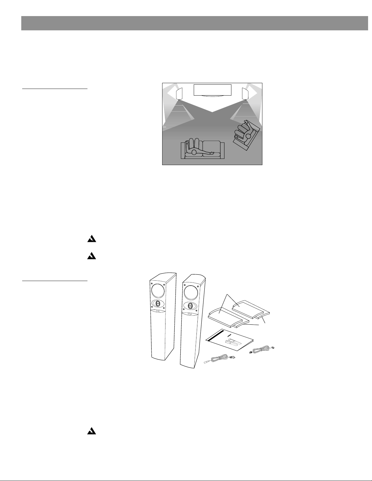
Introduction
Figure 1
A natural balance of direct
and reflected sound.
Your 701
®
Direct/Reflecting
®
speakers re-create a natural balance of reflected and direct
sound energy for a lifelike, spacious performance. As with all Bose
meant to bring you high-quality concert-like sound.
®
products, their design is
Unpacking the speakers
Carefully unpack the contents of the shipping carton.
• Individually remove each speaker.
• Retain the packaging material for possible future use.
• If either speaker appears damaged, do not use it. Repack both speakers in the original car-
ton and notify your authorized Bose dealer immediately.
WARNING: To avoid danger of suffocation, keep the plastic bags that wrap these speakers
out of the reach of children.
WARNING: The left main speaker weighs 50 lb (22.7 kg) and the right accessory speaker
weighs 45 lb (20.4 kg). Use good lifting practice to avoid injury.
Figure 2
Package contents:
• 1 left main speaker
• 1 right accessory speaker
• Owner’s guide
• Power cord
• Bose interconnect cable
• Two front speaker grilles
• Two rear speaker grilles
Left main speaker
Right accessory speaker
Front speaker grilles
Rear speaker grilles
Owner’s guide
Bose interconnect
cable
Power cord
Attaching the speaker grilles
Each speaker has both a front and a rear protective grille. The rear grille is the larger of the
two. To attach these grilles to your speakers, line up the top curve of the grille so that it
matches the curve of the speaker. Align the pins on the back of the grille to the mounting
holes on the speaker cabinet and gently push the grille straight on.
CAUTION: To prevent any damage to the speakers or electronics, be sure to keep the rear
grilles on at all times. Do not place objects into any opening on the speaker cabinets.
4 October 25, 2001 AM257817_00_V.pdf
Page 5

Placing the speakers
2 ft. minimum
.6 m
2 ft. minimum
.6 m
The product label on the back of each speaker indicates LEFT or RIGHT. For best acoustic
performance, place the left speaker on the left side as you face the front of your room and
place the right speaker on the right side of your room.
Keep the speakers 6 - 15 feet (1.8 - 6 m) apart and at least 12 inches (30 cm) from side walls
(see Figure 3).
It is important not to block the acoustic components at the rear of each speaker. To avoid
this, place each speaker 10 inches (25 cm) from the wall behind it.
Figure 3
Ideal speaker placement
Setting Up
10"
minimum (25 cm)
12" minimum
(30 cm)
6 - 15 ft
(1.8 - 6 m)
Figure 4
Place each speaker at least
2 feet (.6 m) from your TV
screen.
®
Note: Bose
®
701
speakers are not intended to hang from walls, or to stand on shelves or
tables. They are designed as floor-standing speakers only.
WARNING: To prevent personal injury , do not place your speakers in high-traffic ar eas wher e
they can be accidentally knocked over.
Note: To prevent interference with your TV picture quality, place each speaker at least 2 feet
(.6 m) from your TV screen.
AM257817_00_V.pdf October 25, 2001 5
Page 6

Setting Up
Choosing the speaker cord
It is important to use the proper gauge (thickness) of speaker cord. Standard zip cord (2-conductor, 18-gauge or .82 mm
2
wire or larger) is recommended for most applications. You can
find this wire at most electrical and hardware stores.
If the length of speaker wire extends more than 30 feet (9 m) from a r eceiver or amplifier, refer
to “Wire recommendations” on page 11 or contact your authorized Bose
®
dealer for more
information.
Note: If you require longer cable runs, or have speaker wire already installed in the wall, the
Bose AC-7 adapter kit is available to accommodate this. The kit will also allow for the use of a
larger gauge speaker wire. Refer to the enclosed list for correct phone numbers to order
PN262061.
Running the speaker cord through a wall or under a floor
Make sure you have enough cord to reach from the receiver to the left main speaker. The
Bose interconnect cable is not intended for in-wall installation. For in-wall installation, check
your local building code requirements. Before proceeding, you may want to contact an electrical installer for information about your local building or safety regulations.
Preparing the speaker cord
Speaker cord consists of two insulated wires. The insulation around one wire is marked
(striped, collared, ribbed, or may have writing on it). This marked wire is always positive (+).
The plain wire is always negative (–). These wires correspond to the red (+) and black (–) terminals on the speaker, receiver, or amplifier.
Note: It is sometimes difficult to distinguish wire markings. Inspect both wires carefully.
3
To prepare the ends of the cord, strip approximately
1
⁄
to
/
inch (12 mm) of insulation from
8
2
both wires. Then, twist the bare ends of each wire so there are no loose strands of wire.
WARNING: Never use broken or frayed wiring, as damage or electrical shock may result.
Making the connections
Your 701
LEFT and RIGHT outputs from your receiver or amplifier must connect to the left main 701
speaker. Please follow the connection instructions carefully to ensure proper performance.
Figure 5 on page 7 indicates how the speakers are connected to the receiver.
Connecting to the receiver
Connect your speaker wire to the SPEAKERS A or MAIN (front) left and right speaker outputs
on your amplifier or receiver. See your receiver owner’s guide for any additional information or
instructions.
CAUTION: Before making any connections, turn off your receiver and unplug it from the AC
power mains. Failure to do so may result in damage to your system.
®
speaker system connects differently from conventional speaker systems. Both the
6 October 25, 2001 AM257817_00_V.pdf
Page 7

Making the connections (cont.)
Output
Input
LFE/
Subwoofer
L
R
L
R
Left main speaker
Receiver
125/115C
225W
Power
Output
Input
LFE/
Subwoofer
L
R
Input
Power
Output
Inpu
Left main speaker
Right accessory speaker
Figure 5
Wiring schematic
Setting Up
L
L
R
R
Power
LFE/
Output
Input
125/115C
Subwoofer
225W
Figure 6
Connecting the right accessory speaker to the left
main speaker
Press down the terminal tab on the bottom of the left main speaker to insert the appropriate
wire (Figure 5).
1. Connect one cord to the left speaker output of your receiver or amplifier.
A. Insert the marked wire at one end to the red (+) terminal.
B. Insert the plain wire at that end to the black (–) terminal.
2. Connect the other end of the cord to the left (L) main speaker terminals (Figure 5).
A. Insert the marked wire into the red (+) terminal.
B. Insert the plain wire into the black (–) terminal.
3. Repeat steps 1 and 2 for the right (R) speaker connections.
Note: The right speaker outputs are located on the left main speaker directly below the left
speaker outputs. They are labeled with an R.
Connecting the right accessory speaker to the left main speaker
Use the supplied Bose
connector at each end is designed to be inserted in one orientation only. Match the curved
top of the connector to the curved top of the jack on the rear connector cups.
CAUTION: Never connect the right accessory speaker directly to a receiver output. Always
connect the right accessory speaker to the left main speaker, then connect the left main
speaker to the receiver.
®
interconnect cable to make this connection. It is important to note the
AM257817_00_V.pdf October 25, 2001 7
Page 8

Setting Up
Input
LFE/
Subwoofer
L
R
LFE/
Subwoofer
Output
Power
Output
Input
LFE/
Subwoofer
L
R
Figure 7
Connecting the LFE input to
your receiver
Connecting the LFE subwoofer input
If your receiver or amplifier has a Subwoofer or Low Frequency Effects (LFE) channel output,
use a single RCA male to RCA male patch cord to make the connection. Connect the “LFE/
Subwoofer” input on the left main speaker to the LFE/subwoofer output of your receiver or
amplifier (Figure 7). Refer to the LFE level control section on page 9.
L
R
Power
LFE/
Output
Input
125/115C
Subwoofer
L
R
225W
Receiver
Right accessory speaker Left main speaker
Note: Now is a good time to record the serial numbers of these speakers on page 3 of this
guide and on your warranty card.
Checking the connections
Check all the connections from the receiver to the left main speaker and from the left main
speaker to the right accessory speaker. Make sure all the wires are connected in phase (+ to
+ and – to –).
Correct any wiring problems before you plug in your receiver or speakers and turn them on.
Plugging in the left main speaker
Once you have checked all the connections, insert one end of the supplied power cord to the
“Power” jack on the left main speaker. Insert the other end of the power cord into an AC
power mains. Plug your receiver or amplifier back into the AC power mains. Then, turn on the
left main speaker power switch (Figure 8). Turning the power switch on puts the speakers in a
standby mode. Finally, turn on your receiver or amplifier power switch.
During normal use, the left main speaker power switch should be left on and the system
should be controlled through the receiver. However, if the speakers will not be used for an
extended period of time, you should turn the left main speaker power switch off.
Note: The left main speaker power switch must be turned on for the speakers to work prop-
erly. If it is not turned on, there will be no bass.
Figure 8
Turning on the left main
speaker power switch
8 October 25, 2001 AM257817_00_V.pdf
Page 9

Setting Up
Setting your non-digital receiver
After making the connections, you may try additional surround sound modes that your
receiver may have. These modes may have different names depending on the manufacturer,
e.g. ACTION, MOVIE, THEATER. Select the settings for music, movies, or both that sound
best in your listening environment. See your receiver/amplifier owner’s guide for additional
information on selecting settings.
CAUTION: 701
most kinds of damage from electrical stress or overload. This circuit activates at high volume
levels to reduce output, causing a slight decrease in volume. You may also notice light coming from inside the speaker cabinet. This is normal operation and indicates that power input
may be exceeding safe levels. Sustained listening at these levels is not recommended.
Setting your digital receiver
Your speakers are fully compatible with the output from most receivers containing digital
technology. The table below suggests the recommended settings. Because they are fullrange speakers, select LARGE on the digital screen menu. Turn the subwoofer and the LFE
(low frequency effects) on. The preferred crossover setting should be 150 Hz.
®
speakers incorporate an automatic protection circuit, which guards against
Speaker Receiver setting
Bass and LFE controls
Your left main speaker has two control knobs – one for bass control and one for LFE control.
Follow the instructions below for using these controls.
Bass control
The bass control, located on the outside of the left main speaker, can help you customize the
speakers to your listening room. Turning the control to the right will add bass to the sound in
rooms that might be characterized as too shrill. Turning the control to the left will “brighten”
the sound of the listening room. As with LFE control, you may find the factory setting to be
completely appropriate for your listening room.
LFE level control
The LFE control, located on the outside of your left main speaker, increases or decreases the
relative level of low frequency effects on movie sound tracks. Use it to regulate the presence
of these underlying deep bass sounds. You may find it unnecessary to adjust this control. The
factory, or detent, setting is appropriate for a majority of listening situations.
Left and right front LARGE
Center SMALL
Surround SMALL
Subwoofer ON
LFE ON
AM257817_00_V.pdf October 25, 2001 9
Page 10

Reference Information
Troubleshooting
If you are experiencing problems with your 701
1. Turn off the amplifier or receiver and check all the connections between the speakers,
2. Check your amplifier or receiver owner’s guide, since other components may be the
3. Use the chart below as troubleshooting guidelines. If this does not solve the problem,
Problem Possible cause How to find out Solution
amplifier, or receiver.
cause of the problem.
contact your authorized Bose
correct phone numbers.
®
speakers:
®
dealer to arrange for service. Refer to the enclosed list for
One speaker
doesn’t play or
sounds distorted
Both speakers do
not play, or sound
distorted
High sound volume
drops suddenly
Defective amplifier
or receiver channel,
or defective speaker
Defective amplifier
or receiver
The automatic protection circuit has
activated to protect
the speakers from
electrical stress or
overload
Switch the LEFT
and RIGHT input
connections on the
back of your left
main speaker.
Disconnect the
amplifier or receiver
from the speakers.
Lower the volume. If
it returns to normal,
your speakers’
automatic protection circuit caused
the sudden drop.
This volume reduction protects the
speakers from electronic stress and
overload.
If the previously
“broken” speaker
now plays properly,
and the other one
does not, one channel in the amplifier
or receiver is probably defective. If the
original speaker still
does not play properly, call Bose or
your retailer to
arrange for service.
Reconnect the
speakers to another
amplifier or receiver
that is working
properly.
Return the volume
to a reasonable level
and avoid extremely
high volume settings.
No bass Left main speaker is
not plugged in or
the power switch is
not turned on
Weak bass Subwoofer/LFE
level or bass level
set too low
Check all connections – especially
AC power.
Check knob positions on the left
main speaker.
Be sure all connections are made and
the amplifier/
receiver is on.
Adjust knob positions to desired set-
ting.
Check receiver settings.
Distorted sound or
diminished sound
quality
Out-of-phase wiring Check connections.
They should be in
phase (+ to + and
Adjust connections,
if they are out of
phase.
– to –).
10 October 25, 2001 AM257817_00_V.pdf
Page 11

Technical Information
Power rating
USA/Canada: 120V ~ 50/60 Hz, 260 W
Europe/Australia: 220-240V ~ 50/60 Hz, 260 W
Features
• Direct/Reflecting
• Stereo Everywhere
• Automatic protection circuitry
• Syncom
Speaker driver complement
• One 8" (20.3 cm) woofer per cabinet
• One 6
• One 2" (5.1 cm) ferrofluid-cooled tweeter
• One 3" (7.6 cm) tweeter per cabinet
Compatibility
Compatible with A/V receivers and amplifiers rated from 10 to 300 watts per channel, rated
from 4 to 8 ohms.
Finish
• Deep charcoal
• Natural wood grain
Dimensions/Weight
39"H x 8"W x 161⁄2"D (99 cm x 20 cm x 42 cm)
Left main speaker is 50 lb (22.7 kg); right accessory speaker is 45 lb (20.4 kg)
Wire recommendations
Based on maximum frequency response deviation of 0.5 dB
®
speaker technology
®
speaker technology
®
computer quality control
1
⁄
" (16.5 cm) mid-range driver per cabinet
2
Reference Information
Gauge Length
18 (0.82 mm
16 (1.3 mm2)
14 (2.1 mm2)
12 (3.3 mm2)
2
)
20 ft (6 m) maximum
30 ft (9 m) maximum
50 ft (15 m) maximum
80 ft (24 m) maximum
Customer service
For additional help in solving problems, contact Bose® customer service. See the enclosed
list of Bose customer service offices and phone numbers.
Cleaning
Wipe the 701® speaker cabinets using a dry cloth. Do not use solvents or chemicals. Do not
allow liquids to spill on or objects to drop into the speaker grilles. You may vacuum the grilles
carefully; the drivers are directly behind the grille cloth. No other maintenance is needed.
AM257817_00_V.pdf October 25, 2001 11
Page 12

©2001 Bose Corporation, The Mountain,
Framingham, MA 01701-9168 USA
257817 AM Rev.00 JN10651
 Loading...