

Page 1
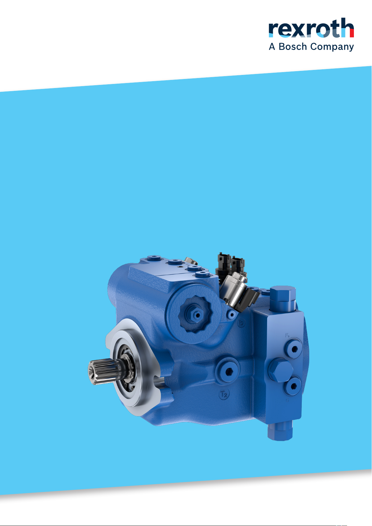
Axial piston
variable pump
A10VG series 60
Operating instructions
RE 92760-01-B/2024-07-16, EN
Page 2

The data specied within only serve to
describe the product. As our products are
constantly being further developed, no
statements concerning a certain condition
or suitability for a certain application can be
derived from our information. The information
given does not release the user from the
obligation of own judgment and verication.
It must be remembered that our products
are subject to a natural process of wear and
aging.
© BoschRexrothAG 2024. All rights reserved,
also regarding any disposal, exploitation,
reproduction, editing, distribution, as well
as in the event of applications for industrial
property rights.
The products and congurations shown in this
document are examples. The supplied product
or conguration may therefore differ from the
gure.
The original operating instructions were
prepared in German.
Page 3

Contents | A10VG series 60 3/64
Contents
1 About this documentation ........................................................................ 5
1.1 Validity of the documentation .......................................................................5
1.2 Required and supplementary documentation ...............................................5
1.3 Representation of information ......................................................................6
1.3.1 Safety instructions .......................................................................................6
1.3.2 Symbols .......................................................................................................7
1.3.3 Designations ................................................................................................7
1.3.4 Abbreviations ...............................................................................................8
2 Safety instructions ................................................................................... 9
2.1 About this chapter ........................................................................................9
2.2 Intended use ................................................................................................9
2.3 Improper use ................................................................................................9
2.4 Personnel qualications .............................................................................10
2.5 General safety instructions .........................................................................11
2.6 Product-specic safety instructions ............................................................12
2.7 Personal protective equipment ...................................................................15
3 General instructions on property damage and product damage .............. 16
4 Scope of delivery.................................................................................... 19
5 About this product ................................................................................. 20
5.1 Performance description ............................................................................20
5.2 Product description ....................................................................................20
5.2.1 Functional description ................................................................................20
5.3 Bypass function (optional) .........................................................................22
5.3.1 Activating and deactivating the bypass function .........................................22
5.4 Product identication .................................................................................24
6 Transport and storage ............................................................................25
6.1 Transporting the axial piston unit ...............................................................25
6.1.1 Transport by hand ......................................................................................25
6.1.2 Transport with lifting devices .....................................................................26
6.2 Storing the axial piston unit .......................................................................28
7 Installation............................................................................................. 30
7.1 Unpacking ..................................................................................................30
7.2 Installation conditions ................................................................................30
7.3 Installation position ...................................................................................32
7.3.1 Below-reservoir installation (standard) ......................................................33
7.3.2 Above-reservoir installation ........................................................................34
7.4 Installing the axial piston unit ....................................................................34
7.4.1 Preparation ................................................................................................34
7.4.2 Dimensions ................................................................................................35
7.4.3 General instructions ...................................................................................35
7.4.4 Installation with acoupling ........................................................................36
7.4.5 Installation on agearbox ............................................................................37
7.4.6 Installation with cardan shaft .....................................................................37
7.4.7 Completion of installation ..........................................................................37
7.4.8 Hydraulically connecting the axial piston unit ............................................39
7.4.9 Electrically connecting the axial piston unit ...............................................43
7.5 Performing ushing cycle ...........................................................................44
RE 92760-01-B/2024-07-16, BoschRexrothAG
Page 4

4/64 A10VG series 60 | Contents
8 Commissioning ....................................................................................... 45
8.1 Initial commissioning .................................................................................45
8.1.1 Filling the axial piston unit .........................................................................45
8.1.2 Testing the hydraulic uid supply ...............................................................47
8.1.3 Performing afunctional test .......................................................................47
8.2 Running-in phase ........................................................................................48
8.3 Recommissioning after standstill ................................................................48
9 Operation ............................................................................................... 49
10 Maintenance and repair .......................................................................... 50
10.1 Cleaning and care ......................................................................................50
10.2 Inspection ..................................................................................................50
10.3 Maintenance ...............................................................................................51
10.4 Repair ........................................................................................................52
10.5 Spare parts ................................................................................................52
11 Removal and replacement ...................................................................... 53
11.1 Required tools ............................................................................................53
11.2 Preparing for removal .................................................................................53
11.3 Performing the removal ..............................................................................53
11.4 Preparing the components for storage or further use .................................53
12 Disposal ................................................................................................. 54
13 Extension and conversion .......................................................................55
14 Troubleshooting ..................................................................................... 56
14.1 How to proceed for troubleshooting ...........................................................56
14.2 Malfunction table .......................................................................................57
15 Technical data ........................................................................................ 61
16 Alphabetical index ................................................................................. 62
BoschRexrothAG, RE 92760-01-B/2024-07-16
Page 5
About this documentation | A10VG series 60 5/64
1 About this documentation
1.1 Validity of the documentation
This documentation applies to the following products:
• Axial piston variable pump A10VG series 60
This documentation is intended for machine/system manufacturers, assemblers and
service engineers.
This documentation contains important information on the safe and proper
transport, installation, commissioning, operation, maintenance, removal and simple
troubleshooting of the axial piston unit.
▶ Read this documentation completely, in particular chapter2 "Safety instructions"
on page9 and chapter3 "General instructions on property damage and
product damage" on page16 before you start work with the axial piston unit.
1.2 Required and supplementary documentation
▶ Only commission the axial piston unit if the documentation marked with the
book symbol
is available to you and you have understood and observed it.
Table 1: Required and supplementary documentation
Title Document number Document type
Order conrmation
Contains the order-related technical data for your axial piston variable pump
A10VG.
Installation drawing
Contains the outer dimensions, all ports and the hydraulic circuit diagram for
your axial piston variable pump A10VG.
Axial piston variable pump A10VG series 60
Contains the permissible technical data, ports, main dimensions and circuit
diagrams of standard versions.
Hydraulic uids based on mineral oils and related hydrocarbons
Describes the requirements for mineral oil-based hydraulic uids and related
hydrocarbons for operation with Rexroth hydraulic components and provides
support for selection of suitable hydraulic uids for the hydraulic system.
Environmentally acceptable hydraulic uids
Describes the requirements for environmentally acceptable hydraulic uids on
mineral oil basis and related hydrocarbons for operation with Rexroth hydraulic
components, and provides support for selection of suitable hydraulic uids for
the hydraulic system.
Fire-resistant, water-free hydraulic uids (HFDR/HFDU)
Describes the requirements on re-resistant, water-free hydraulic uids
(HFDR/HFDU) for operation with Rexroth hydraulic components and assists
you in selecting ahydraulic uid for your hydraulic system.
– Order conrmation
Please request the
installation drawing
from your contact at
BoschRexroth.
92760 Data sheet
90220 Data sheet
90221 Data sheet
90222 Data sheet
Installation drawing
RE 92760-01-B/2024-07-16, BoschRexrothAG
Page 6
6/64 A10VG series 60 | About this documentation
Table 1: Required and supplementary documentation
Title Document number Document type
Axial piston units for operation with re-resistant hydraulic uids
(HFDR, HFDU, HFA, HFB, HFC, HFC-E)
Describes the requirements on re-resistant, water-free and water-containing
hydraulic uids (HFDR, HFDU, HFA, HFB, HFC, HFC-E) and contains the
technical data for operation with Rexroth hydraulic components.
BODAS hall effect angle and linear position sensor PAL, series 10
Contains the permissible technical data and dimensions.
BoschRexroth Fluid Rating List for Rexroth hydraulic components
(pumps and motors)
Contains the hydraulic uids positively evaluated by BoschRexroth.
Application instructions for axial piston units in the low temperature range
Contains additional information on the application of Rexroth axial piston units
at low temperatures.
Storage and preservation of axial piston units
Contains additional information on storage and preservation.
BODAS-drive eDA application software
BODAS-drive eDA is asoftware solution integrated in the Rexroth SRC-eDA1/31
control unit for controlling the hydrostatic drive train in wheeled vehicles.
90225 Data sheet
95161 Data sheet
90245 Data sheet
90300-03 Application
90312 Data sheet
95316 Data sheet
information
1.3 Representation of information
Uniform safety instructions, symbols, terms and abbreviations are used throughout
this documentation to ensure safe and proper use of the product. For clarication,
they are explained in the sections below.
1.3.1 Safety instructions
This documentation contains safety instructions in chapter2.6 "Product-specic
safety instructions" on page12 and in chapter3 "General instructions on
property damage and product damage" on page16, as well as before asequence
of actions or a handling instruction involving arisk of personal injury and property
damage. Always follow the measures for danger prevention associated with the use
of this product.
Safety instructions are set out as follows:
SIGNAL WORD
Type and source of danger!
Consequences of non-compliance
▶ Danger prevention measures
• Warning sign: draws attention to the danger
• Signal word: identies the degree of the danger
• Type and source of danger: indicates the type and source of the danger
• Consequences: describes the consequences of non-compliance
• Precautions: states how the danger can be avoided
BoschRexrothAG, RE 92760-01-B/2024-07-16
Page 7
About this documentation | A10VG series 60 7/64
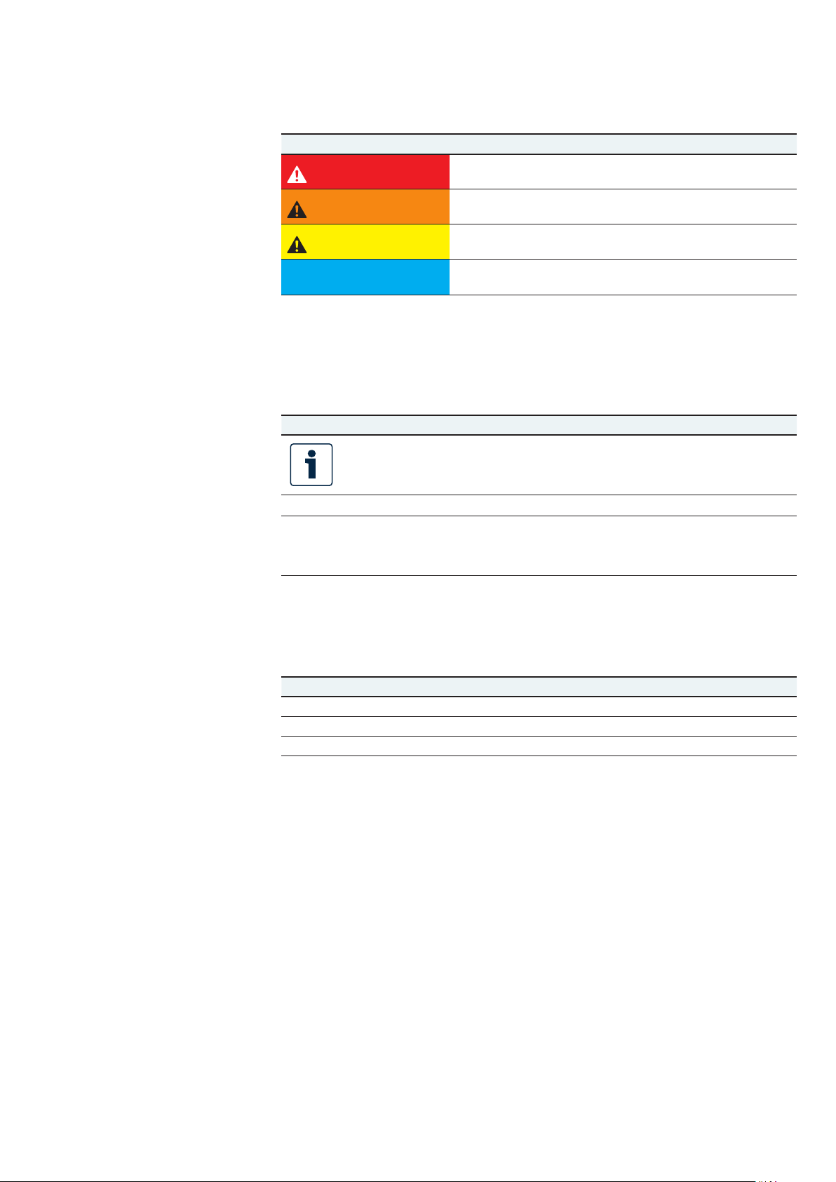
Table 2: Hazard classes as dened in ANSI Z535.6
Warning sign, signal word Meaning
Identies adangerous situation that will result in death or
DANGER
WARNING
CAUTION
NOTICE
1.3.2 Symbols
The following symbols indicate instructions that are not safety-relevant but increase
understanding of the documentation.
Table 3: Meaning of symbols
Symbol Meaning
If this information is disregarded, the product cannot be used and/or
operated to its full extent.
serious personal injury if it is not avoided.
Identies adangerous situation that may result in death or
serious personal injury if it is not avoided.
Identies adangerous situation that may result in minor to
moderate personal injury if it is not avoided.
Property damage: The product or surrounding area may be
damaged.
▶
1.
2.
3.
1.3.3 Designations
This documentation uses the following designations:
Table 4: Designations
Designation Meaning
A10VG Axial piston variable pump, closed circuit
Threaded plug Metal screw, pressure-resistant
Protective plug Made out of plastic, not pressure-resistant, only for transportation
As generic term for "axial piston variable pump A10VG", the designation
"axial piston unit" will be used in the following.
Single, independent action
Numbered handling instruction:
The numbers indicate that the action steps must be completed in order.
RE 92760-01-B/2024-07-16, BoschRexrothAG
Page 8

8/64 A10VG series 60 | About this documentation
1.3.4 Abbreviations
This documentation uses the following abbreviations:
Table 5: Abbreviations
Abbreviation Meaning
ANSI American National Standards Institute is an organization that coordinates
the development of voluntary standards in the United States
ATE X EC directive on explosion protection (Atmosphère explosible)
DIN Deutsches Institut für Normung (German Institute for Standardization)
ET Electronic, direct acting control
ISO International Organization for Standardization
JIS Japan Industrial Standard
RE Rexroth document in the English language
VDI2230 Guideline for the systematic calculation of heavy-duty
threaded connections and cylindrical screw joints from the VDI
(VereinDeutscherIngenieure - Association of German Engineers)
BoschRexrothAG, RE 92760-01-B/2024-07-16
Page 9

Safety instructions | A10VG series 60 9/64
2 Safety instructions
2.1 About this chapter
The axial piston unit has been manufactured to generally accepted engineering
standards. There is still, however, arisk of personal injury or property damage if
this chapter and the safety instructions in this documentation are not observed.
▶ Read this documentation completely and thoroughly before working with the
axial piston unit.
▶ Keep this documentation in alocation where it is accessible to all users at all
times.
▶ Always include the required documentation when you pass the axial piston unit
on to third parties.
2.2 Intended use
Axial piston units are hydraulic components, meaning that in their application area
they are classied neither as complete nor as partly completed machinery in the
sense of the EC Machinery Directive 2006/42/EC. The component is exclusively
intended to form partly completed machinery or complete machinery together with
other components. The component should only be commissioned after it has been
installed in the machine/system for which it is intended, and the safety of the
entire system has been established in accordance with the Machinery Directive.
This product is intended for the following use:
The axial piston unit is only approved as apump for hydrostatic drives in closed
circuit.
▶ Observe the technical data, the application and operating conditions and
the performance limits as specied in the data sheet92760 and in the order
conrmation. Information about approved hydraulic uids can be found in data
sheet 92760.
The axial piston unit is only intended for commercial use and not for private use.
Intended use includes having fully read and understood this documentation,
especially chapter2 "Safety instructions" on page9.
2.3 Improper use
Any use other than that described as intended use is considered improper.
BoschRexrothAG is not liable for damage resulting from improper use. The user is
solely responsible for any risks arising from improper use.
The following foreseeable forms of faulty usage are also considered improper
(this list is not exhaustive):
• Use outside the operating parameters approved in the data sheet and in the order
conrmation (unless specically approved by the customer)
• Use of non-approved uids, e.g.water or polyurethane components
• Changes to factory settings by unauthorized persons
• Use of assembled parts (e.g. control unit, valves) not in combination with the
specied Rexroth components
• Use of the axial piston unit with assembled parts under water at adepth greater
than 10 meters without the necessary additional measures, e.g.pressure
equalization. Units with electrical components (e.g.sensors) must not get
into contact with water, depending on the IP protection class. Observe the
IP protection class in the data sheet92760.
RE 92760-01-B/2024-07-16, BoschRexrothAG
Page 10

10/64 A10VG series 60 | Safety instructions
• Use of the axial piston unit under acontinuous pressure differential between
the housing and ambient pressure greater than 2bar absolute, with the case
pressure always greater than the external pressure on the shaft seal ring
(ambient pressure). Short-term (t <0.1 s) max. 1000case pressure peaks up
to 10 bar absolute are permitted. Beyond this, the maximum permissible case
pressure specied in the data sheet should not be exceeded.
• Application of the axial piston unit in explosive environments unless the
component or machine/system has been certied as compliant with the ATEX
Directive 2014/34/EU
• Use of the axial piston unit in acorrosive atmosphere
• Use of the axial piston unit in aircraft or spacecraft
2.4 Personnel qualications
The activities described in this documentation require abasic understanding
of mechanics, electricity and hydraulics, as well as familiarity with associated
technical terms. For transporting and handling the product, knowledge regarding
the use of lifting devices and lifting accessories is required. In order to ensure safe
use, these activities should only be performed by skilled personnel or an instructed
person under the direction and supervision of skilled personnel.
Skilled personnel refers to persons who possess the professional training,
knowledge and experience, as well as the understanding of the regulations relevant
to the work to be done that are necessary to recognize possible dangers and take
the appropriate safety measures. Skilled personnel must follow the rules relevant
to their eld and have the necessary hydraulic expert knowledge.
Hydraulic expert knowledge includes:
• Being able to read and fully understand hydraulic circuit diagrams
• In particular, fully understanding the relationships with regard to safety devices
• Knowledge regarding the function and interaction of hydraulic components
BoschRexroth offers you measures supporting training in specic areas.
You can nd an overview of the training contents on the Internet at:
www.boschrexroth.com/training.
BoschRexrothAG, RE 92760-01-B/2024-07-16
Page 11

Safety instructions | A10VG series 60 11/64
2.5 General safety instructions
• Observe the country-specic accident prevention and environmental protection
regulations.
• Observe the safety regulations of the country in which the product is
used/operated.
• Use Rexroth products only when they are in good working order.
• Observe all instructions on the product.
• Do not assemble, operate, remove or maintain Rexroth products if under the
inuence of alcohol, drugs or medication that may affect your reaction time.
• Only use genuine Rexroth accessories and spare parts to ensure there is no
hazard to persons from unsuitable spare parts.
• Observe the technical data and ambient conditions specied in the product
documentation.
• If unsuitable products are installed or used in safety-relevant applications,
unexpected operating conditions may occur in the application, which could result
in personal injury or property damage. For this reason, only use the product in
safety-relevant applications if this use is expressly indicated and approved in the
product documentation, e. g.in explosion protection areas or in safety-related
parts of acontrol system (functional safety).
• Only commission the product if it has been determined that the end product
(e.g.machinery/system) in which the Rexroth products are installed complies
with the country-specic provisions, safety regulations and standards for the
application.
• Use tools appropriate for the work being performed and wear appropriate
protective clothing to prevent punctures and cuts (e.g.when removing protective
covers, disassembly).
• There is arisk of entanglement when operating the axial piston unit with
abare shaft end. Check whether or not your machine requires additional safety
measures for your application. If necessary, make sure these are appropriately
implemented.
• Depending on the type of control used, electromagnetic effects can be produced
when using solenoids. Applying a direct voltage signal (DC) to solenoids does
not create electromagnetic interference (EMI) nor is the solenoid affected
by EMI. Potential electromagnetic interference (EMI) exists if the solenoid is
energized with amodulated direct current (e.g.PWM signal). Appropriate testing
and measures should be taken by the machine manufacturer to ensure other
components or operators (e.g.with pacemaker) are not affected by this potential.
• The swivel angle sensor assembly group contains a permanent magnet. As most
types of electronic storage media are sensitive to magnetic elds, they have to
be stored separately from permanent magnets. Persons with implanted cardiac
pacemakers must take special precautions. Magnets may have a nickel coating,
which can lead to allergic reactions.
RE 92760-01-B/2024-07-16, BoschRexrothAG
Page 12

12/64 A10VG series 60 | Safety instructions
2.6 Product-specic safety instructions
The following safety instructions apply to chapters 6 to 14.
Danger due to excessive pressure!
Risk of death or injury, or property damage!
Improperly changing the pressure settings congured at the factory can result in
apressure increase beyond the permissible maximum pressure.
Operating the unit above the maximum permissible pressure can cause
components to burst and hydraulic uid to escape under high pressure.
▶ Changes to the factory settings may only be made by BoschRexroth specialists.
▶ Pressure cut-off (hydraulic or electronic) is not a sufcient safeguard against
pressure overload. Therefore, a pressure relief valve must be added to the
hydraulic system (integrated into the pump or externally in the system).
Observe the technical limits of the pressure relief valves here.
Danger due to suspended loads!
Risk of death or injury, or property damage!
Improper transportation may cause the axial piston unit to fall down and lead to
injury, e.g.crushing or fracture, or damage to the product.
▶ Make sure that the load bearing capacity of the lifting device is sufcient to
safely bear the weight of the axial piston unit.
▶ Never step or grip under suspended loads.
▶ Ensure astabletransport position.
▶ Use your personal protective equipment (e.g.safety goggles, safety gloves,
suitableworking clothes, safety shoes).
▶ Use suitablelifting devices for transport.
▶ Observe the prescribed position of the lifting strap.
▶ Observe the national laws and regulations on occupational health and safety,
and transportation.
WARNING
System/machine under pressure!
Risk of death or serious injury when working on unsecured machines/systems!
Property damage!
▶ Switch off the relevant machine/system part and secure it against reactivation
according to the parameters by the machine/system manufacturer.
▶ Ensure that all relevant components of the hydraulic system are depressurized.
For this purpose, observe the parameters indicated by the machine/system
manufacturer.
▶ Please note that the hydraulic system might still be pressurized even after
separation from the actual pressure supply.
▶ Do not disconnect any line connections, ports or components as long as the
hydraulic system is under pressure.
BoschRexrothAG, RE 92760-01-B/2024-07-16
Page 13

Safety instructions | A10VG series 60 13/64
WARNING
Escaping hydraulic uid mist!
Risk of explosion and re hazard, health hazard, risk of environmental pollution!
▶ Depressurize the relevant machine/system component and repair the leak.
▶ Only perform welding work when the machine/system is depressurized.
▶ Keep open ames and ignition sources away from the axial piston unit.
▶ If axial piston units are located in the vicinity of ignition sources or powerful
thermal radiators, ashield must be erected to ensure any escaping hydraulic
uid cannot be ignited, and to protect hose lines from premature aging.
Escaping hydraulic uid due to leakage of machine/system components!
Risk of burning and risk of injury due to escaping hydraulic uid jet!
In case of leakage at the axial piston unit, high-pressure uid jets may escape.
▶ Depressurize the relevant machine/system component and repair the leak.
▶ Never attempt to block or seal the leak or hydraulic uid jet with acloth.
Hydraulic uid will explode when making contact with water!
Explosion and re hazard!
▶ Do not bring hot hydraulic uids in contact with water.
Electrical voltage!
Danger to life or risk of injury due to electric shock or property damage!
▶ Always disconnect the voltage supply to the relevant machine/system
part before installing the product and/or connecting or disconnecting the
connector. Protect the machine/system against being re-energized.
Danger from unexpected machine movement!
Danger to life or risk of injury! Unintentional or careless actuation of the manual
override of the solenoids can cause unexpected machine movements.
▶ Use the manual override only for functional testing or in the event of technical
malfunctions.
▶ Using the manual override on apermanent basis (e.g.by wedging, blocking) is
not permitted.
▶ The use of the manual override is only permitted with limited technical data
(e.g.0.25×maximum data).
▶ The manual override is pushed by hand and may only be actuated with the
rubber bellows intact. Actuation without the rubber bellows or using other
mechanical means or tools is not permissible.
▶ Check whether or not your machine requires additional safety measures for
your application to avoid unintentional actuation. If necessary, make sure
these are appropriately implemented.
▶ Wear suitable protective clothing.
RE 92760-01-B/2024-07-16, BoschRexrothAG
Page 14

14/64 A10VG series 60 | Safety instructions
Restriction of control function!
Risk of injury or property damage!
Under certain circumstances, moving parts in control equipment (e.g., valve
spools) can get stuck in an undened position due to contamination (e.g., impure
hydraulic uid, abrasion or residual dirt from components). As aresult, the
hydraulic uid ow and the build-up of torque in the axial piston unit can no
longer respond correctly to the operator’s specications. Even the use of various
lter elements (external or internal ow ltration) will not rule out afault but
merely reduce the risk.
▶ Check whether your application requires remedial measures on your machine
in order to bring the driven consumer to asafe position (e.g.safe stop).
▶ If necessary, make sure these are appropriately implemented.
Limitation of load-holding function in lifting winches!
Risk of injury or property damage!
Moving parts in high-pressure relief valves may in certain circumstances become
stuck in an undened position due to contamination (e.g.impure hydraulic uid).
This can result in restriction or loss of load-holding functions in lifting winches.
The load-holding capacity of the unit depends on its conguration.
▶ Check whether the application on your machine requires additional safety
measures in order to keep the load in asafe position.
▶ If necessary, make sure these are appropriately implemented.
WARNING
Risk of pressurized hydraulic uid leaking or ying components!
Danger to life or risk of injury! When selecting or using connecting elements
without sufcient high-pressure resistance, they may burst or lead to the leakage
of hydraulic uid and/or to ejected components. The ports and fastening threads
of the axial piston unit are designed for the specied maximum pressure.
▶ Only ever connect connecting elements and lines that match the ports of
the axial piston unit and can resist the intended application conditions
(e.g.pressure level, ow, hydraulic uid, temperature) with the necessary
safety factors.
BoschRexrothAG, RE 92760-01-B/2024-07-16
Page 15

Safety instructions | A10VG series 60 15/64
CAUTION
High noise development during operation!
Risk of hearing damage or hearing loss!
The noise emission of axial piston units depends on rotational speed, working
pressure and installation conditions, among other factors. The sound pressure
level may rise above 70 dB (A) in certain application conditions.
▶ Always wear hearing protection near arunning axial piston unit.
Hot surfaces on axial piston unit!
Risk of getting burnt!
▶ Allow the axial piston unit to cool down sufciently before touching it.
▶ Wear heat-resistant, protective clothing, e.g.gloves.
Improper cable and line routing!
Risk of stumbling and property damage! Improper routing of cables and lines
can cause arisk of stumbling as well as damage to equipment and components,
e.g.due to lines and connectors being torn off.
▶ Always lay cables and lines so no one can trip over them, they do not become
kinked or twisted, do not rub on edges and do not run through sharp-edged
ducts without adequate protection.
Contact with hydraulic uid!
Risk of adverse health effects, e.g.eye injury, skin irritation, toxication from
inhalation!
▶ Avoid any contact with hydraulic uids.
▶ When handling hydraulic uids, the safety instructions of the lubricant
manufacturer need to be observed at all times.
▶ Use your personal protective equipment (e.g.safety goggles, safety gloves,
suitableworking clothes, safety shoes).
▶ Immediately seek medical attention, however, if hydraulic uid gets into your
eyes or blood circuit or if you swallow it accidentally.
Danger from improper handling!
Slip hazard and risk of property damage! Risk of slipping when climbing on the
axial piston unit. Parts and components may be damaged.
▶ Never grab or climb onto the axial piston unit.
▶ Check how to safely get on top of the machine/system.
2.7 Personal protective equipment
Personal protective equipment is the responsibility of the user of the axial piston
unit. Observe the safety regulations in your country.
All pieces of personal protective equipment must be intact.
RE 92760-01-B/2024-07-16, BoschRexrothAG
Page 16

16/64 A10VG series 60 | General instructions on property damage and product damage
3 General instructions on property
damage and product damage
The following information applies to chapters 6 to 14.
NOTICE
Danger from improper handling!
Product can be damaged!
▶ Do not subject the product to improper mechanical loads.
▶ Never use the product as handle or step.
▶ Do not put/place any objects on the product.
▶ Do not strike the drive shaft of the axial piston unit.
▶ Do not set/place the axial piston unit on the drive shaft or assembled parts.
▶ Do not strike assembled parts (e.g. sensors, solenoids or valves).
▶ Do not hit sealing surfaces (e.g.on the work connections).
▶ Leave the protective covers on the axial piston unit until you connect the lines.
▶ Disconnect all electrical connectors before any electric welding and painting
work.
▶ Make sure the electronic components (e.g.sensors) do not build up
electrostatic charges (e.g.during painting operations).
Risk of property damage due to inadequate lubrication!
Product can be damaged or destroyed!
▶ Never operate the axial piston unit with insufcient hydraulic uid.
Specically, make sure that the rotary group has sufcient lubrication.
▶ When commissioning amachine/system, make sure that the housing area and
the working lines of the axial piston unit are lled with hydraulic uid and
remain lled during operation.
▶ For above-reservoir installation, the housing area may drain out through
the drain line after prolonged standstill periods or through the working line
(gap leakage). This means the bearings are insufciently lubricated when the
system is turned on.
▶ Make sure the suction line is always lled with hydraulic uid during
commissioning and operation.
Mixing hydraulic uids!
Product can be damaged!
▶ Any mixture of hydraulic uids of different manufacturers and/or different
types of the same manufacturer is generally not permissible.
BoschRexrothAG, RE 92760-01-B/2024-07-16
Page 17

General instructions on property damage and product damage | A10VG series 60 17/64
NOTICE
Contamination of hydraulic uid!
The cleanliness of the hydraulic uid considerably impacts the service life of the
axial piston unit. Contamination of the hydraulic uid may lead to premature
wear and malfunctions!
▶ Always ensure awork environment in the assembly location that is free
from dust and foreign particles to prevent foreign particles, e.g.welding
beads or metal cuttings, from entering the hydraulic lines and lead to wear
and malfunctions in the product. The axial piston unit must be clean when
installed.
▶ Only use clean ports, hydraulic lines and assembled parts (e.g.measuring
devices).
▶ When plugging the ports, no contamination must ingress.
▶ Before commissioning, ensure that all hydraulic connections are tight and that
all seals are correctly installed and undamaged to prevent uids and foreign
particles from entering the product.
▶ Filter the hydraulic uid when lling the system with asuitablelter system
to minimize the solid particle contamination and water in the hydraulic system
and to achieve the required cleanliness level.
Improper cleaning!
Product can be damaged!
▶ Plug all openings with appropriate protective covers in order to prevent
cleaning agents from entering the axial piston unit.
▶ Never use solvents or aggressive cleaning agents. Use only water and,
if necessary, amild cleaning agent to clean the axial piston unit.
▶ Do not point ahigh-pressure cleaner at sensitive components,
e.g.shaft seal, electrical connections and components.
▶ Use ber-free cleaning cloths for cleaning.
Environmental pollution due to improper disposal!
Careless disposal of the axial piston unit and its assembled parts, the hydraulic
uid and the packaging material can cause environmental pollution!
▶ Dispose of the axial piston unit, hydraulic uid and packaging in accordance
with the regulations in your country.
▶ Dispose of the hydraulic uid in accordance with the applicable safety data
sheet for the hydraulic uid.
Danger from chemical or corrosive environmental conditions!
Product can be damaged! If the axial piston unit is exposed to chemical or
corrosive environmental conditions, such as sea water, fertilizer or road salt,
it can result in corrosion or, in extreme cases, malfunction. Leaks may lead to
leakage of hydraulic uid.
▶ Take appropriate measures to protect the axial piston unit from chemical or
corrosive environmental conditions.
RE 92760-01-B/2024-07-16, BoschRexrothAG
Page 18

18/64 A10VG series 60 | General instructions on property damage and product damage
NOTICE
Leakage or spilling of hydraulic uid!
Risk of environmental pollution and contamination of ground water!
▶ Always place adrip tray under the axial piston unit when lling and draining
hydraulic uid.
▶ Use asuitable binding agent to collect any leaked hydraulic uid.
▶ Observe the parameters in the safety data sheet for the hydraulic uid and the
specications provided by the machine/system manufacturer.
Danger from hot components!
Nearby products can be damaged! Components which heat up (e.g.,solenoids)
can cause damage to nearby products if they are too close during installation.
▶ When installing the axial piston unit, check the safety distances to nearby
products to ensure that they are not damaged.
The warranty only applies to the machine conguration as delivered.
The warranty will be voided if the product is incorrectly installed, commissioned or
operated, or if it is used or handled improperly.
BoschRexrothAG, RE 92760-01-B/2024-07-16
Page 19
Scope of delivery | A10VG series 60 19/64
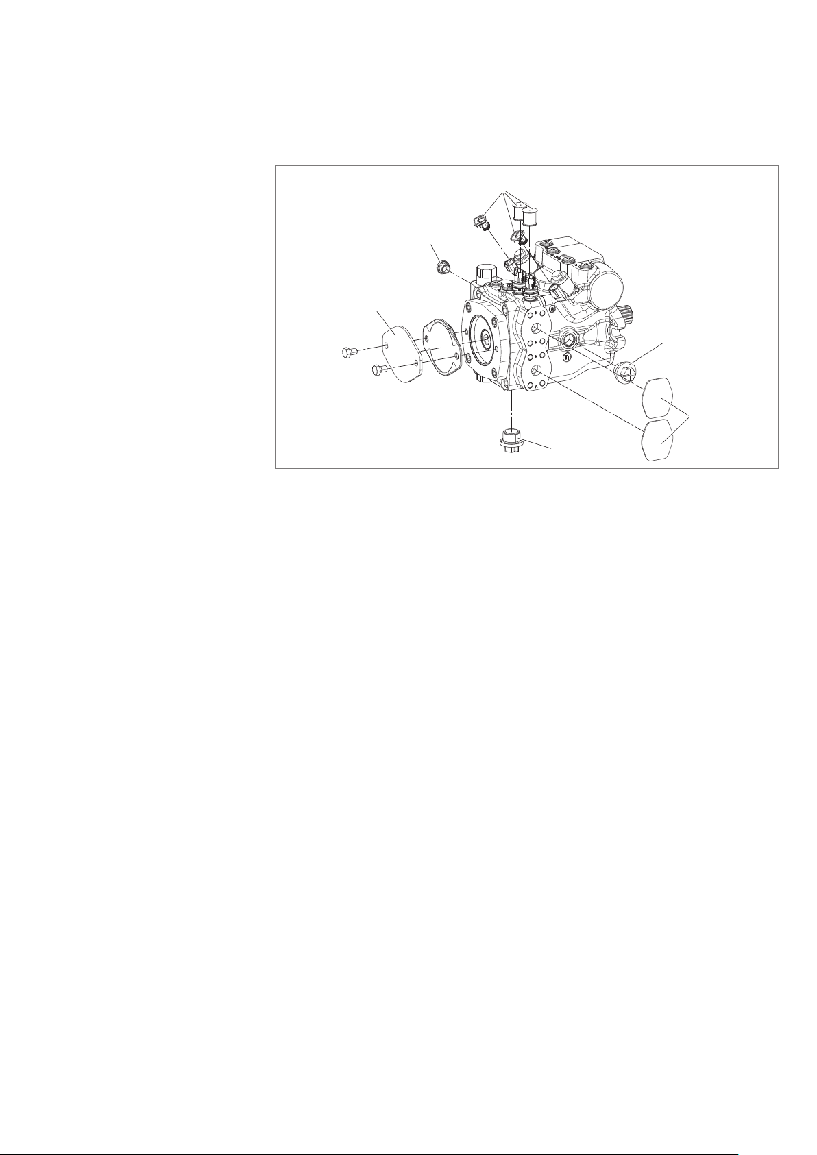
4 Scope of delivery
3
2
4
2
1
2
Fig. 1: Axial piston unit
Included in the scope of delivery:
• Axial piston unit as per order conrmation
The following parts come assembled on the unit:
• Protective covers (1)
• Protective plug/threaded plugs(2)
• Protective covers for sensors and connectors (3)
• For version with through drive, protective cover incl. xing screws (4)
RE 92760-01-B/2024-07-16, BoschRexrothAG
Page 20

20/64 A10VG series 60 | About this product
5 About this product
5.1 Performance description
The Axial piston variable pump generates, controls and regulates ahydraulic uid
ow. It is designed for mobile applications, e.g. construction machinery.
Refer to data sheet 92760 and the order conrmation for the technical data,
operating conditions and application limits of the axial piston unit.
5.2 Product description
A10VG is avariable pump with an axial piston rotary group in swashplate design
for hydrostatic drives in closed circuits. Flow is proportional to drive speed and
displacement. The ow can be smoothly changed by control (cradle). For axial
piston units with swashplate design, the pistons are arranged axially relative to the
drive shaft.
Closed circuit
Pump function
Control
In the closed circuit, the hydraulic uid ows from the hydraulic pump to the
consumer, e.g. hydraulic motor and from there directly back to the hydraulic pump.
There is ahigh-pressure side and alow-pressure side which alternate depending on
which side is under load.
5.2.1 Functional description
Torque and rotational speed are applied to the drive shaft by adrive motor. The drive
shaft is connected to the cylinder by splines, causing the cylinder to rotate. With every
revolution, the pistons perform astroke in the cylinder bores, the size of which
depends on the pitch of the cradle. The slipper pads are held on with the pistons and
guided along the glide surface of the cradle by the retaining plate.
The pitch of the swashplate during arevolution causes each piston to move over
the bottom and top dead centers and back to its initial position.
Hydraulic uid is supplied and discharged through two control slots in the control
plate according to the displacement. On the high-pressure side, the hydraulic uid
is pushed out of the cylinder chamber and into the hydraulic system by the pistons.
At the same time, hydraulic uid ows into the growing piston chamber on the lowpressure side. In aclosed circuit, this is supported by the return ow and boost
pressure.
The swivel angle of the cradleis innitely variable. Adjusting the swivel angle
changes the piston stroke and, with it, the displacement. Control across the neutral
position will change the direction of ow (making reversing operation possible).
The swivel angle is controlled hydraulically by means of the stroking piston.
The cradle is mounted in swivel bearings for smooth operation and the neutral
position is spring-centered. Increasing the swivel angle increases the displacement;
reducing the angle reduces displacement accordingly.
BoschRexrothAG, RE 92760-01-B/2024-07-16
Page 21
About this product | A10VG series 60 21/64
High-pressure
safeguarding
Version with
boost pump
Version without boost
pump (external boost
pressure supply)
Version with swivel angle
sensor (optional)
The two high-pressure relief valves protect the hydrostatic gear (pump and motor)
from overloading. They limit the maximum pressure in the respective high-pressure
line and serve simultaneously as boost valves. The high-pressure relief valves are
exclusively intended to protect the system from high-pressure peaks until the
control dynamics of the pressure cut-off ensure the intended maximum working
pressure. An electronic pressure cut-off must be provided for permanent highpressure limitation.
The boost pump supplies output ow (boost ow), from a reservoir, proportional
to the pump input speed via the check valve of the high-pressure relief valves to the
low-pressure side of the closed circuit. This replaces leakages of the pump and the
consumers in the closed circuit, and where applicable the ushing ows of ushing
valves. The boost pump is an internal gear pump which is driven directly via the
drive shaft.
In order to replace the leakages of the variable pump and consumers, portG must
be connected to an external source of boost pressure. The boost-pressure relief
valve is integrated.
The swivel angle sensor PAL is used for contactless detection of the swivel angle of
axial piston units using aHall effect-based sensor IC. The measured position is
converted into electric signals by the redundant swivel angle sensor.
For further information on the use of the swivel angle sensor PAL in the axial piston
unit, consult your local contact person. You can nd their contact information at
https://addresses.boschrexroth.com
For information on the swivel angle sensor PAL, e.g. type code, technical data,
dimensions and safety instructions, see the data sheet A10VG, series 60(92760)
and the data sheet PAL sensor(95161), see Table 1 "Required and supplementary
documentation" on page5.
Notice: It is not possible to retrot existing units with aswivel angle sensor.
Sequence valve
(optional)
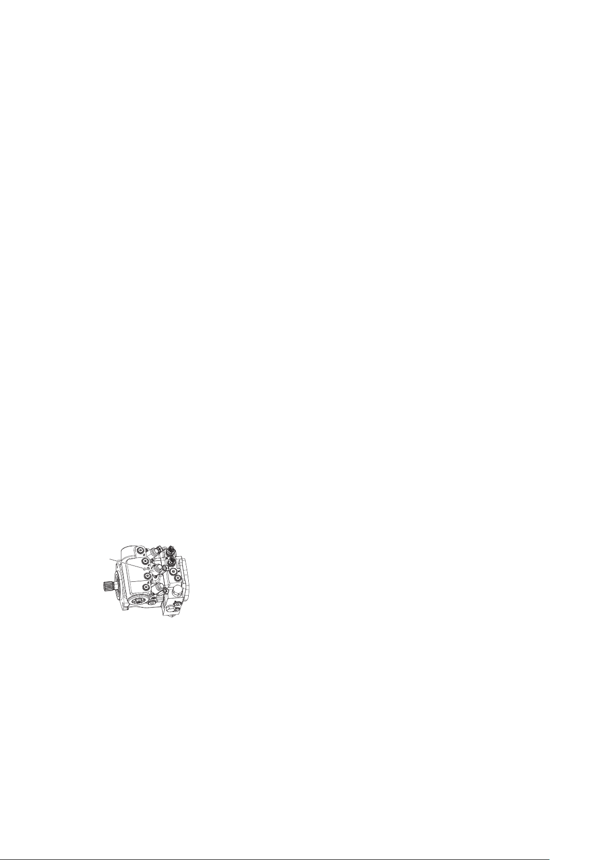
1
The optional sequence valve (1) releases the connection between the boost pump
and control when the solenoid is energized. It interrupts the connection when the
solenoid is de-energized. In addition, the sequence valve vents the stroking
chambers to the reservoir when de-energized. This causes the springs in the
stroking chambers to move the stroking piston towards the central position
(neutral position).
The reset function is inuenced by the current working pressure and rotational
speed.
Interrupting the control pressure does not ensure that the pump moves to the
central position (neutral position).
▶ Check whether remedial measures are needed on the machine for the
application concerned in order to bring the driven consumer into asafe position
(e.g.safe stop) and ensure any measures are properly implemented.
RE 92760-01-B/2024-07-16, BoschRexrothAG
Page 22
22/64 A10VG series 60 | About this product
Flushing valve
(optional)
2
The purpose of the optional ushing valve (2) is to remove heat from the hydraulic
circuit. Hydraulic uid is ushed out of the low-pressure side of the closed circuit
via the ushing spool from a pressure differential between A and B of 3 bar and
low pressure of 16 bar. It is necessary to replace both the ushing ow and the
internal leakage of the axial piston units with a boost pressure supply. The boost
pressure supply with ltered and cooled hydraulic uid lowers the circuit
temperature. The ushing ow is determined by an orice in the ushing valve.
This depends on the orice size, the pressure differential between the low pressure
and the pressure in the drain line, as well as the viscosity. A pressure retention
valve is also integrated in the ushing valve. As soon as the pressure level falls
below the set retention pressure, e.g. due to excessive ushing ow, the pressure
retention valve reduces the ushing ow and thus prevents impermissible pressure
drops, e.g. due to excessively low rotational speeds. The valve is mounted to the
port plate.
For information on the control device, see data sheet 92760.
5.3 Bypass function (optional)
For vehicles with hydrostatic travel drive, as long as there is no downstream
mechanical interruption of the drive train (switch to idle/freewheeling), the ow
can be altered using abypass circuit in order to tow the vehicle out of the
immediate danger zone. Turning the corresponding screw allows the hydraulic
uid to ow freely.
If necessary, BoschRexroth recommends always activating the bypass function
on both pressure relief valves (avoiding afunction in only one travel direction).
The bypass function must be deactivated again before restarting the machine.
5.3.1 Activating and deactivating the bypass function
1
2
1
2
2
1
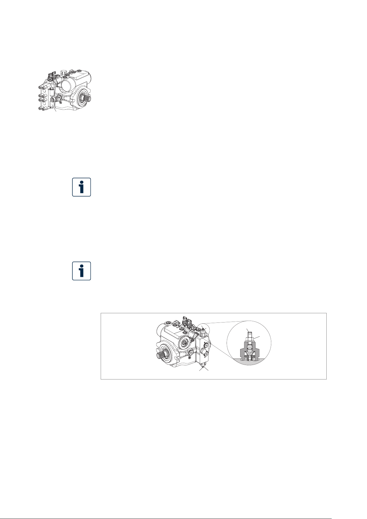
Fig. 2: Activating the bypass function
BoschRexrothAG, RE 92760-01-B/2024-07-16
Page 23

About this product | A10VG series 60 23/64
Activating the
bypass function
Towing speed
Towing distance
To activate the bypass function:
1. Switch off the combustion engine.
2. Loosen the lock nut (2) by turning it counterclockwise one half-turn with an
external hexagon wrench (WAF 13).
3. Use ahexagon socket wrench (WAF4) to turn the screw(1) clockwise until
the screw(1) is against the spring seat. This is indicated by the increased
resistance. Then turn the screw (1) to clockwise by another half turn.
4. Tighten the lock nut (2) clockwise to atorque of 22 Nm.
The maximum towing speed depends on the gear ratio in the vehicle and must be
calculated by the vehicle manufacturer. The corresponding ow of q
= 30 l/min
V
may not be exceeded.
CAUTION! Excessive heat generation and inadequate lubrication!
Risk of getting burnt or property damage. High towing speeds and long towing
distances lead to excessive heat generation and inadequate lubrication.
The axial piston unit heats up as a result, causing damage.
▶ Wear heat-resistant protective clothing, e.g. gloves.
▶ Only tow the vehicle out of the immediate danger zone.
Only tow the vehicle out of the immediate danger zone.
Deactivating the
bypass function
NOTICE! Draining of the hydraulic circuit!
Risk of damage! While towing with the bypass function activated and the drive
motor deactivated, the closed hydraulic circuit drains itself. This can lead to
damage due to excessive heat development.
▶ Start the vehicle, drive off carefully and slowly until the hydraulic circuit has
lled and bled.
To deactivate the bypass function:
1. Immediately following towing, switch off the bypass function.
2. Restore the function of the high-pressure relief valve. To do this, perform the
settings made under item "Activating the bypass function" in the reverse order:
Loosen the lock nut (2) with an external hexagon wrench (WAF 13), then turn
the screw (1) counter-clockwise with ahexagon socket wrench (WAF 4) to
the stop.
3. Re-tighten the lock nut (2), turning clockwise to atorque of 22 Nm.
RE 92760-01-B/2024-07-16, BoschRexrothAG
Page 24
24/64 A10VG series 60 | About this product
5.4 Product identication
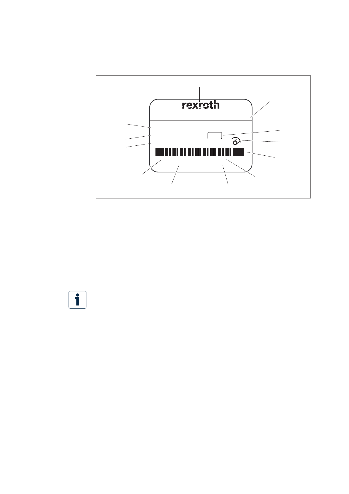
The axial piston unit can be identied by the name plate. The following example
shows an A10VG name plate:
1
2
TYP:
12
MNR:
11
SN:
SC: X
10
FD:
n = XXXX min
9
Fig. 3: Name plate A10VG
1 Trademark
2 Type code
3 Internal ID
4 Direction of rotation
(viewed on drive shaft) – here:
clockwise
5 Bar code
6 Weight (optional)
DE-89275 Elchingen
A10VG45ETA0P/60MRNB2S51U0000A1S000-0
R90XXXXXXX
12345678
24W29
-1
Made in Germany
8
7202
Rotation:
m: XXX kg
P = XXX kW
7
7 Power (optional)
8 Rotational speed (optional)
9 Manufacturing date
10 Sample category (optional)
11 Serial number
12 Material number of the axial
piston unit
3
4
5
6
The inspection stamp is located next to the name plate on the axial piston unit.
BoschRexrothAG, RE 92760-01-B/2024-07-16
Page 25

Transport and storage | A10VG series 60 25/64
6 Transport and storage
▶ Always observe the required ambient conditions for transport and storage;
see chapter6.2 "Storing the axial piston unit" on page28.
Information on unpacking can be found in chapter7.1 "Unpacking" on page30.
6.1 Transporting the axial piston unit
NOTICE
Danger from improper handling!
Product can be damaged!
▶ For the version with manual override, the actuation elements on the magnets
may be mechanically loaded at most with a maximum static force of 200N,
both during transport and by depositing the axial piston unit on the magnets
of the emergency manual actuation. No sudden force shall be applied to the
magnets (e.g. by impact).
Dimensions and weights
The following transportation options are available depending on weight and
duration of transport:
• Transport by hand
• Transporting with alifting device (eye bolt or lifting strap)
Table 6: Dimensions and weights
Size 45
Weight kg 34.3
Width mm Dimensions vary by equipment. The values applicable for your axial piston
Height mm
Depth mm
Weight may vary by equipment.
6.1.1 Transport by hand
Up to aspecic maximum weight, axial piston units can be transported by hand
for ashort distance. Observe the national regulations in your country. To prevent
health damage, we recommend renouncing any transport by hand.
CAUTION! Risk of injury due to heavy loads!
Health hazard from carrying axial piston units.
▶ Only manually transport the axial piston unit for ashort period of time.
Observe the national regulations in your country for manual transport.
▶ Always use appropriate lifting, lowering and moving techniques.
▶ Use your personal protective equipment (e.g.safety goggles, safety gloves,
suitableworking clothes, safety shoes).
unit can be found in the installation drawing (request if necessary).
RE 92760-01-B/2024-07-16, BoschRexrothAG
Page 26
26/64 A10VG series 60 | Transport and storage
▶ Do not transport the axial piston unit by sensitive assembled parts
(e.g.sensors, magnets, or valves).
▶ Carefully place the axial piston unit on the seating to prevent it from being
damaged.
6.1.2 Transport with lifting devices
For transporting, the axial piston unit can be connected to alifting device via
an eye bolt in the drive shaft or in the housing. Alternatively, it can also be
transported with alifting strap. When selecting the means of transport, consider
the permissible total weight.
Only use the lifting strap if you are unable to achieve the required installation
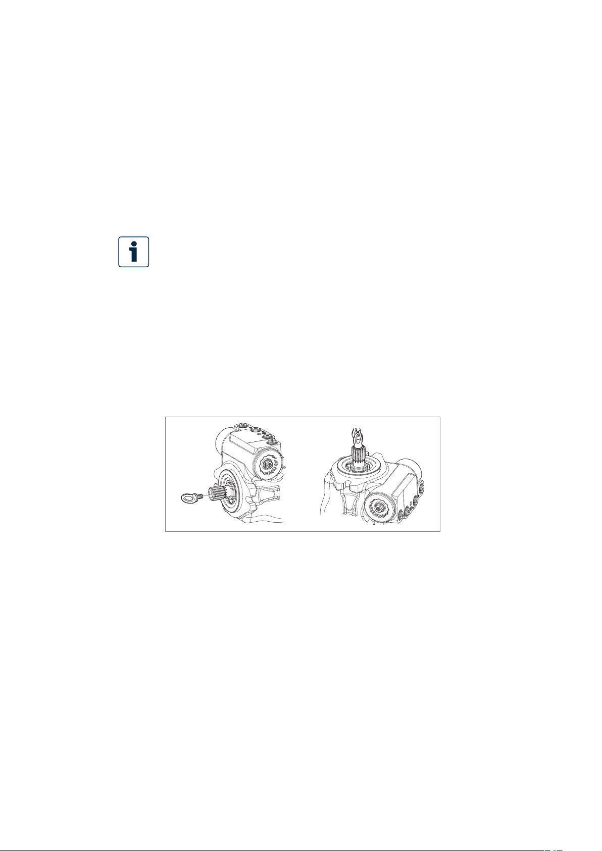
position with transport using the eye bolts.
Transporting with
eye bolt in drive shaft
Transporting with
eye bolt in housing
(possible with standard
version without swivel
angle detection)
The axial piston unit can be transported suspended from an eye bolt screwed into
the drive shaft as long as only outward (pulling) axial forces are applied.
▶ For all female threads, use astud end from the same system of units and of the
correct size.
▶ To do this, screw an eye bolt completely into the female thread on the drive
shaft. The thread size is indicated in the installation drawing.
▶ Make sure that the eye bolt can bear the total weight of the axial piston unit
plus 20%.
You can lift the axial piston unit as shown in Fig. 4 with the eye bolt screwed into
the drive shaft.
Fig. 4: Mounting the eye bolt
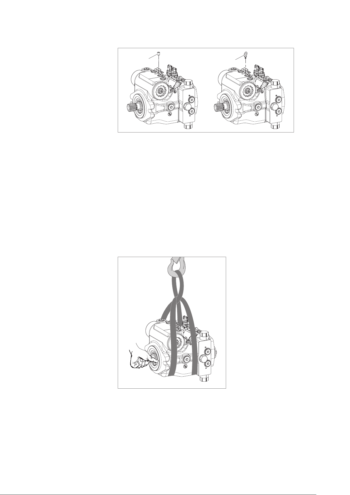
▶ For all female threads, use astud end from the same system of units and of the
correct size (M8).
▶ Screw the eye bolt fully into the female thread in the housing.
▶ Make sure that the eye bolt can bear the total weight of the axial piston unit
plus approx. 20%.
You can hoist the axial piston unit as shown in Fig. 5 with the eye bolt(2) screwed
into the housing. Remove the M10grub screw(1) before using a size5 hexagon
socket wrench.
BoschRexrothAG, RE 92760-01-B/2024-07-16
Page 27
Transport and storage | A10VG series 60 27/64
Transport with lifting strap
1
Fig. 5: Mounting eye bolts in housing
2
WARNING! Danger due to suspended loads!
During transport with lifting strap, the axial piston unit can topple out of the lifting
strap and cause injury.
▶ Use the widest possible lifting strap.
▶ Make sure that the axial piston unit is securely xed with the lifting strap.
▶ Only guide the axial piston unit by hand for ne positioning and to avoid
swinging.
▶ Never step or grip under suspended loads.
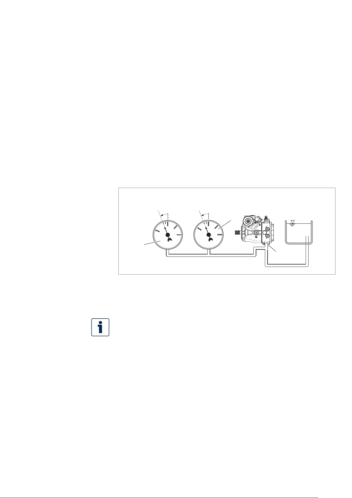
▶ Place the lifting strap around the axial piston unit in such away that it does not
pass over assembled parts (e.g.valves, magnets, or piping) and that the axial
piston unit is not suspended from assembled parts (see Fig. 6).
Fig. 6: Transport with lifting strap
RE 92760-01-B/2024-07-16, BoschRexrothAG
Page 28

28/64 A10VG series 60 | Transport and storage
6.2 Storing the axial piston unit
Requirement
• Storage areas must be free of corrosive materials and gases.
• To prevent damage to the seals, do not operate ozone-forming equipment
(e.g.mercury-vapor lamps, high-voltage equipment, electric motors, sources of
electrical sparks or electrical discharge) in storage areas.
• Storage areas must be dry.
Recommended relative humidity ≤ 60%.
• Ideal storage temperature: +5°C to +20°C.
• Minimum storage temperature: −50°C.
• Maximum storage temperature: +60°C.
• Keep out of direct sunlight.
• Do not stack axial piston units and store them in ashock-proof manner.
• Do not store the axial piston unit on the drive shaft or assembled parts,
e.g.sensors, magnets, or valves.
• For further storage conditions, see Table 7.
▶ Check the axial piston unit monthly to ensure professional storage.
After delivery
The axial piston units come in corrosion protection packaging (corrosion protection
lm) provided at the factory.
Table 7 lists the maximum permissible storage times for an unpackaged axial piston
unit as per data sheet 90312.
Table 7: Storage time with corrosion protection applied at the factory
Storage conditions Standard corrosion
protection
Closed, dry room, uniform
temperature between
+5°C and +20°C.
Undamaged and closed
corrosion protection lm.
Maximum 12 months Maximum 24 months
Long-term corrosion
protection (optional)
The warranty will be voided if the requirements and storage conditions are not
observed or after expiration of the max. storage time (see Table 7).
How to proceed once the max. storage time elapses:
1. Check the entire axial piston unit for damage and corrosion prior to
installation.
2. Perform atest run to check the axial piston unit for proper functioning and
leak-tightness.
3. If storage time exceeds 24 months, replace the shaft seal.
Once the max. storage time has elapsed, we recommend that you have the axial
piston unit checked by your BoschRexroth service partner.
For questions regarding repair and spare parts, contact your proper BoschRexroth
service partner or the service department of the manufacturer's plant of the axial
piston unit, see chapter10.5 "Spare parts" on page52.
BoschRexrothAG, RE 92760-01-B/2024-07-16
Page 29

Transport and storage | A10VG series 60 29/64
In pumps with intermediate ange and spacer versions, the design may cause
humidity to penetrate the seal area and cause corrosion. However, this has no
effect on the function and reliability of the pump.
After removal
An uninstalled axial piston unit must be preserved with corrosion protection for the
storage time.
The following instructions only refer to axial piston units operated with
mineral oil-based hydraulic uid. Other hydraulic uids require other specic
preservation measures. In such acase, consult your local contact person; you
can nd their contact information at
https://addresses.boschrexroth.com
BoschRexroth recommends the following procedure:
1. Clean the axial piston unit; see chapter10.1 "Cleaning and care" on page50.
2. Drain the axial piston unit.
3. For storage times up to 12 months: Moisten the inside of the axial piston unit
with mineral oil and ll with approx. 100 ml mineral oil.
For storage times up to 24 months: Fill the axial piston unit with VCI corrosion
protection oil (20 ml).
Fill through the drain port T
or T2; see chapter7.4 "Installing the axial piston
1
unit", Fig. 10 on page41.
4. Plug all ports so they are airtight.
5. Coat unpainted areas of the axial piston unit with mineral oil or suitable,
easily removable corrosion protection, e.g.acid-free grease.
6. Pack the axial piston unit with desiccant in an airproof manner in corrosion
protection lm.
7. Store the axial piston unit in ashock-proof manner; see "Requirement"
on page 28 in this chapter.
RE 92760-01-B/2024-07-16, BoschRexrothAG
Page 30

30/64 A10VG series 60 | Installation
7 Installation
Prior to installation, the following documents must be to hand:
• Data sheet of the axial piston unit (contains the permissible technical data, main
dimensions and circuit diagrams of standard versions)
• Installation drawing for the axial piston unit (can be obtained from your contact
person at BoschRexroth, if required)
• Hydraulic circuit diagram for the axial piston unit (in the data sheet and on the
installation drawing)
• Hydraulic circuit diagram for the machine/system (available from the machine/
system manufacturer upon request)
• Order conrmation (contains the order-related technical data for your axial
piston unit)
7.1 Unpacking
The axial piston unit comes in apolyethylene material (PE) corrosion protection lm.
CAUTION! Danger due to falling parts!
If the packaging is not opened correctly, parts may fall out and damage the parts or
even result in injury.
▶ Place the packaging on alevel underground with sufcient load-bearing capacity.
▶ Only open the packaging from the top.
▶ Remove the packaging from the axial piston unit.
▶ Check the axial piston unit for transport damage and completeness;
see chapter4 "Scope of delivery" on page19.
▶ Dispose of the packaging in accordance with the regulations in your country.
7.2 Installation conditions
The installation position and location of the axial piston unit essentially determine
how it is installed and commissioned (such as when lling and air bleeding the
axial piston unit).
▶ Fasten the axial piston unit so that the expected forces and torque can be
transferred without any danger. The machine/system manufacturer is responsible
for sizing the fastening elements.
▶ Observe the permissible radial forces on the drive shaft when driving with radial
loading (belt drives).
▶ Make sure the axial piston unit is always lled with hydraulic uid during
commissioning and operation. Also do this also after relatively long standstill
periods, since the axial piston unit may drain out through the hydraulic lines.
▶ Direct the leakage in the housing area to the reservoir through the highest drain
port. Use aline size that matches the port.
▶ Avoid using acheck valve in the drain line.
BoschRexrothAG, RE 92760-01-B/2024-07-16
Page 31
Installation | A10VG series 60 31/64
-0.2
0.8 absolute
1
2
3
0
0
1
2
-1
2
1
S
▶ To prevent the transmission of structure-borne noise, use elastic elements
to decouple all connecting lines from all vibration-capable components
(e.g. reservoir, frame parts).
▶ Make sure the suction, leakage, and return lines ow into the reservoir below
the minimum uid level under all operating conditions. This will prevent air from
being drawn in and foam from forming.
▶ When designing the reservoir, ensure that there is adequate distance between
the suction line and the drain line. We recommend using abafe (bafe plate)
between suction line and drain line. A bafe improves the air separation ability
as it gives the hydraulic uid more time for desorption. Apart from that, this
prevents the heated return ow from being drawn directly back into the suction
line. The suction port must be supplied with ltered, cooled, calmed and
degassed hydraulic uid over a sufcient period of time.
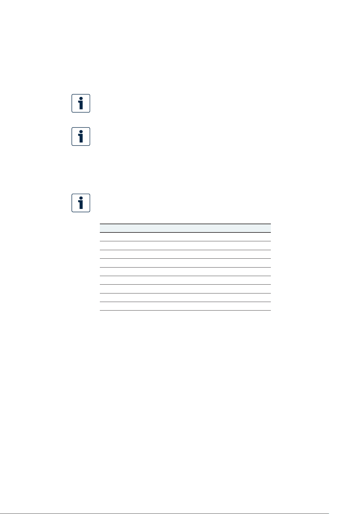
▶ Make sure that aminimum suction pressure of 0.8bar absolute is present
at portS (0.5bar absolute for cold start) during operation in all installation
positions and installation locations for the axial piston pump, see Fig. 7.
See data sheet for other pressure values.
Fig. 7: Suction pressure
1 Absolute pressure gauge
2 Standard pressure gauge (relative)
The suction conditions improve with below-reservoir installation.
▶ Make sure that the working environment at the installation site is completely
free of dust and foreign substances. The axial piston unit must be clean when
installed. Contamination of the hydraulic uid can considerably affect the
function and service life of the axial piston unit.
▶ Use ber-free cleaning cloths for cleaning.
▶ Use suitable, mild cleaning agents to remove lubricants and other heavy
contamination. Do not allow cleaning agents to enter into the hydraulic system.
RE 92760-01-B/2024-07-16, BoschRexrothAG
Page 32
32/64 A10VG series 60 | Installation
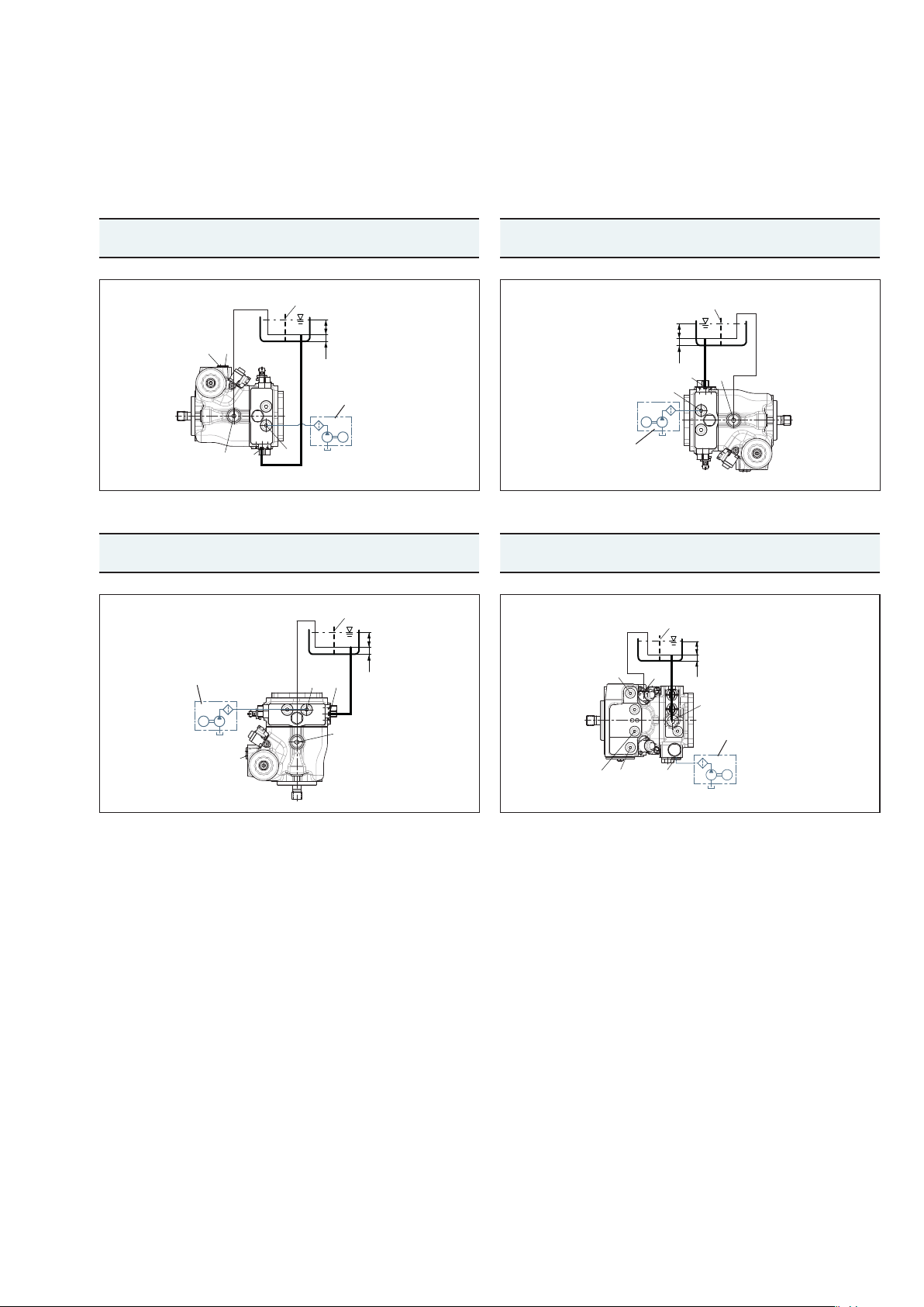
7.3 Installation position
The following installation positions are permissible. The pipeline routing shown
illustrates the basic layout.
Recommended installation position: 1 and 2.
For optimum function and dynamics of the axial piston unit, acomplete lling
of the two stroking chambers X
By swiveling the swashplate several times during commissioning, this can
usually be ensured. In case of unfavorable installation positions, air bleeding
of the stroking chambers may take some time, so we recommend lling the
stroking chambers via ports X
and X2 with hydraulic uid is required.
1
and X2 before installation.
1
In certain installation positions, an inuence on the adjustment or control
can be expected. Gravity, dead weight and case pressure can cause minor
characteristic shifts and changes in response time.
Key
R Air bleed port
S Suction port
T
1, T2
X
1, X2
G Boost pressure port inlet
SB Bafe (bafe plate)
h
t min
h
min
h
S max
Drain port
Control pressure port
Minimum required immersion depth (200 mm)
Minimum required distance to reservoir bottom (100mm)
Maximum permissible suction height (800mm)
BoschRexrothAG, RE 92760-01-B/2024-07-16
Page 33
Installation | A10VG series 60 33/64
7.3.1 Below-reservoir installation (standard)
Below-reservoir installation means that the axial piston unit is installed outside of
the reservoir below the minimum uid level.
Installation position 1 Installation position 2
Air bleeding the
housing
T
, R X1, X
1
Air bleeding the
stroking chamber
2
Filling Air bleeding the
housing
G1), S, T1, X1, X
2
T
2
Air bleeding the
Filling
stroking chamber
– G1), S, T
2
SB
h
t min
R
X2, X
1
G
S
T
1
h
min
Filling unit
M
Filling unit
Installation position 3 Installation position 4
Air bleeding the
housing
T
2
Air bleeding the
stroking chamber
X1, X
2
Filling Air bleeding the
housing
G1), S, T2, X1, X
2
T
1
SB
h
t min
h
Filling unit
M
X2, X
G
S
T
1
min
2
X
1
R
X
2
SB
h
t min
h
min
T
S
2
G
M
2)
Air bleeding the
stroking chamber
X
1
SB
h
t min
T
h
1
min
S
Filling unit
G
M
Filling
G1), S, T1, X1,
1)
Recommendation: Filling with lter/lling unit. When lling without lter/lling unit, the pump must be lled at the highest drain
port.
2)
Port X2 top only permissible upon request.
RE 92760-01-B/2024-07-16, BoschRexrothAG
Page 34
34/64 A10VG series 60 | Installation
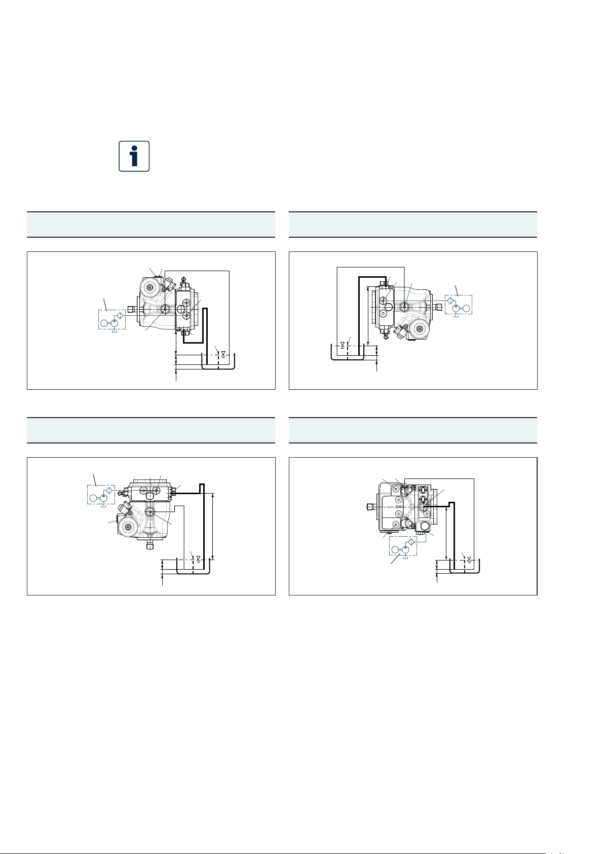
7.3.2 Above-reservoir installation
Above-reservoir installation means that the axial piston unit is installed above the
minimum uid level of the reservoir.
Observe the maximum permissible suction height h
The permissible suction height h
Installation position 5 Installation position 6
Air bleeding
the housing
R X
Filling unit
Installation position 7 Installation position 8
Air bleeding
the housing
T
2
Air bleeding the
stroking chamber
1, X2
, X
X
2
1
M
T
1
h
S max
h
h
Air bleeding the
stroking chamber
X1, X
2
R
t min
min
Filling Air bleeding
the housing
G1), S, T1, X1, X
2
T
G
S
SB
Filling Air bleeding
the housing
G1), S, T2, X1, X
2
T
is derived from the total pressure loss.
S
2
SB
1
= 800 mm.
S max
Air bleeding the
Filling
stroking chamber
– G1), S, T
S
G
T
2
Filling unit
M
h
S max
h
t min
h
min
2)
Air bleeding the
Filling
stroking chamber
X
1
G1), S, T1, X1,
2
Filling unit
M
X2,X
1
1)
Recommendation: Filling with lter/lling unit. When lling without lter/lling unit, the pump must be lled at the highest
h
h
t min
min
G
S
T
2
h
S max
SB
Filling unit
X
T
1
1
S
h
h
h
S max
t min
min
G
SB
X
2
M
drain port.
2)
Port X2 top only permissible upon request.
7.4 Installing the axial piston unit
7.4.1 Preparation
1. Check the specications on the name plate to see you have the correct axial
piston unit.
2. Compare the material number and designation (type code) with the parameters
in the order conrmation.
BoschRexrothAG, RE 92760-01-B/2024-07-16
Page 35
Installation | A10VG series 60 35/64
If the material number for the axial piston unit does not match the one in
the order conrmation, contact your local contact person for clarication.
You can nd their contact information at
https://addresses.boschrexroth.com
3. Before installing, completely drain the axial piston unit to prevent mixing with
the hydraulic uid used in the machine/system.
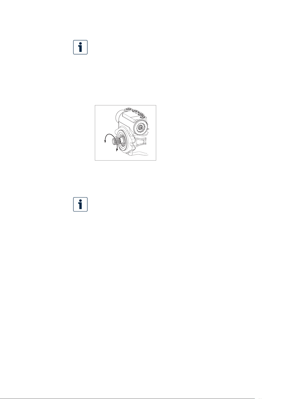
4. Check the permissible direction of rotation of the axial piston unit
(on the name plate) and make sure that this corresponds to the direction of
rotation of the drive motor.
L
R
Fig. 8: Direction of rotation
Counter-clockwise
L
Clockwise
R
The direction of rotation as indicated on the name plate determines the
direction of rotation of the axial piston unit as viewed on the drive shaft;
see chapter5.4 "Product identication" on page24. For information on
the direction of rotation of the drive motor, please refer to the drive motor
manufacturer's operating instructions.
7.4.2 Dimensions
For standard versions, the data sheet92760 contains all required installation
dimensions as well as the position and dimensions of the ports. If necessary,
an installation drawing can be requested. Also observe the manuals provided by the
manufacturers of the other hydraulic components when selecting the required tools.
7.4.3 General instructions
Follow these general instructions when installing the axial piston unit:
• Torsional vibrations and speed variations may cause increased rotary angular
acceleration of the rotary group of the axial piston unit. At risk are diesel drives
with asmall number of cylinders and low ywheel mass and toothed belt or
V-belt drives. Belts can lose much of their pre-charge pressure after just ashort
operating time.
An automatic clamping device can lessen the speed variations and vibrations,
and thus avoid subsequential damage.
– When using drives with toothed belts or V-belts, always use an automatic
clamping device.
• On the drive of an axial piston unit, acardan shaft may cause vibrations
and excessive rotary angular acceleration. Depending on the frequency and
temperature, this may cause leaks in the shaft seal and damage the rotary group.
RE 92760-01-B/2024-07-16, BoschRexrothAG
Page 36

36/64 A10VG series 60 | Installation
• If ashared drain line is used for several units, make sure that the respective case
pressure in each unit is not exceeded. The shared drain line must be dimensioned
to ensure that the maximum permissible case pressure of all connected units is
not exceeded in any operating condition, particularly at cold start. If this is not
possible, separate drain line must be laid.
The version of installation for the axial piston unit depends on the connecting
elements to the drive side. The following descriptions explain the installation of
the axial piston unit:
• With acoupling
• On agearbox
• On acardan shaft
7.4.4 Installation with acoupling
The following describes how to install the axial piston unit with acoupling:
NOTICE! Danger from improper handling!
Product can be damaged!
▶ Do not install the coupling hub on the drive shaft of the axial piston unit by
striking it.
1. Install the specied coupling half on the drive shaft of the axial piston unit
according to the specications of the coupling manufacturer.
The drive shaft of the axial piston unit is equipped with afemale thread.
Use this female thread to pull the coupling element onto the drive shaft.
The size of the female thread can be seen in the installation drawing.
2. Make sure that the installation location is clean and free from dirt and foreign
particles.
3. Clamp the coupling hub onto the drive shaft or ensure permanent lubrication
of the drive shaft. This prevents the formation of frictional corrosion and the
associated wear.
4. Transport the axial piston unit to the installation location.
5. Install the coupling on the output shaft of the drive motor in accordance with
the specications provided by the coupling manufacturer.
Do not fasten down the axial piston unit until the coupling has been correctly
assembled.
6. Fasten the axial piston unit at the installation location.
7. Align the drive shaft of the axial piston unit and the output shaft of the drive
motor so there is no angular deviation.
Make sure no excessive axial and radial forces are acting on the drive shaft.
8. Details on the required tools and tightening torques for the xing screws are
available from the machine/system manufacturer.
BoschRexrothAG, RE 92760-01-B/2024-07-16
Page 37

Installation | A10VG series 60 37/64
7.4.5 Installation on agearbox
The following describes how to install the axial piston unit on agearbox.
After installing on agearbox, the axial piston unit is covered and is difcult to
access:
▶ Before installing, make sure that the spigot diameter centers the axial piston
unit (observe tolerances) and that no excessive axial or radial forces are acting
on the drive shaft of the axial piston unit (installation length).
▶ Protect the drive shaft against frictional corrosion by ensuring permanent
lubrication.
▶ Fasten the axial piston unit at the installation location.
For attachment via
gear wheel or helical
gear shaft
No spline forces higher than the permissible axial and radial forces should act on
the shaft; if necessary, support the gear wheel at the gearbox output separately.
7.4.6 Installation with cardan shaft
Bring the axial piston unit to the installation position and fasten it. Details of the
required tools and tightening torque for the xing screws can be obtained from the
machine/system manufacturer.
NOTICE! Damage to the axial piston unit and leaks at the shaft seal due to
incorrectly installed cardan shaft!
Improperly installed cardan shafts generate unbalances. This results in vibrations
and inadmissible axial and radial forces on the drive shaft.
▶ Observe the cardan shaft manufacturer's assembly instructions.
7.4.7 Completion of installation
1. Remove any installed transport screws.
CAUTION! Operation with protective plugs!
Operating the axial piston unit with protective plugs may result in injury or damage
to the axial piston unit.
▶ Before commissioning, remove all protective plugs and replace them with
suitable, pressure-resistant, metal threaded plugs or connect the appropriate
lines.
2. Remove the transport protection.
The axial piston unit comes with protective covers (1), (3) and protective
plugs (2). (1) and (2) not pressure-resistant and have to be removed prior to
connection. Use asuitabletool for this to prevent damage to the sealing and
functional surfaces. If sealing or functional surfaces are damaged, contact your
BoschRexroth service partner or the service department of the manufacturer's
plant of the axial piston unit.
RE 92760-01-B/2024-07-16, BoschRexrothAG
Page 38
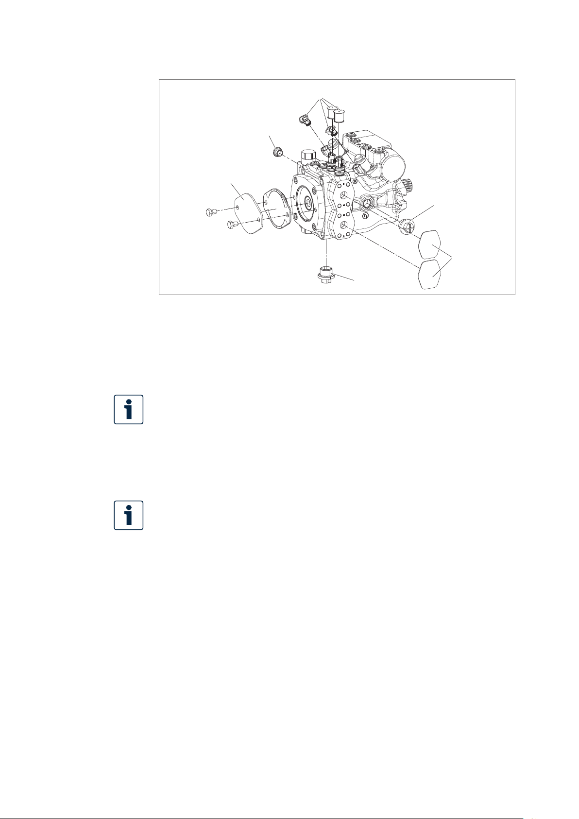
38/64 A10VG series 60 | Installation
Fig. 9: Removing transport protection
3
2
4
2
1
2
1 Protective covers
2 Protective plugs/threaded plugs
3 Protective covers for sensors and
connectors
Ports intended for connecting lines come with protective plugs and/or
threaded plugs, which serve as transport protection. Connect all ports required
for functional operation (see Table 8 "Hazard classes as dened in ANSI
Z535.6eries 60" on page41). Non-compliance could lead to malfunctions
or damage. If aport is not connected, plug it with athreaded plug since the
protective plugs are not pressure-resistant.
Setting screws are protected against unauthorized adjustment by tamper-proof
caps. Removal of the tamper-proof caps will void the warranty. If you need to
change the settings, please contact your local contact person. You can nd
their contact information under
https://addresses.boschrexroth.com
3. For versions with through drive, install the auxiliary pump according to the
pump manufacturer's manual. The protective cover (4) is not pressure-resistant
and therefore not permissible during operation.
For the design of the xing screws, observe VDI2230 with μ=0.1 and screw
quality8.8.
4 For version with through drive,
protective cover and xing screws
BoschRexrothAG, RE 92760-01-B/2024-07-16
Page 39

Installation | A10VG series 60 39/64
7.4.8 Hydraulically connecting the axial piston unit
NOTICE
Insufcient suction pressure!
Generally, aminimum permissible suction pressure at portS is specied for axial
piston pumps in all installation positions. If the pressure at portS drops below
the specied values, damage may occur which may lead to the destruction of the
axial piston pump!
▶ Make sure the required suction pressure is maintained. This is inuenced by:
– The piping (e.g.suction cross-section, pipe diameter, length of suction line)
– The position of the reservoir
– The viscosity of the hydraulic uid
– A lter element or check valve in the suction line (check the level of
contamination of the lter element regularly)
– The geodesic height of the place of use
The machine/system manufacturer is responsible for dimensioning of the lines.
Connect the axial piston unit to the rest of the hydraulic system in accordance with
the hydraulic circuit diagram of the machine/system manufacturer.
The ports and fastening threads are designed for the p
the respective ports, see Table 8 "Hazard classes as dened in ANSI Z535.6eries
60" on page41. The machine/system manufacturer is required to ensure that the
connecting elements and lines correspond to the specied application conditions
(pressure, ow, hydraulic uid, temperature) with the necessary safety factors.
permissible pressures of
max
Information on
routing of lines
Connect only hydraulic lines that are match the axial piston unit port
(pressure level, size, system of units).
Observe the following information when routing the suction, pressure and
drain lines.
• Lines and hoses must be assembled without pre-charge pressure so no further
mechanical forces are applied during operation that will reduce the service life of
the axial piston unit and, possibly, the entire machine/system.
• Use suitable seals as sealing material.
• Suction line (pipe or hose)
– The suction line should be as short and straight as possible.
– Measure the cross-section of the suction line so that the pressure at the suction
port does not drop below the minimum permissible pressure. Make sure the
maximum suction pressure is not exceeded (e.g.when prelling).
– Make sure the connections and connecting elements are airtight.
– The hose must be pressure-resistant, also to external air pressure.
• Pressure line
– For the pressure lines, use only pipes, hoses and connecting elements rated for
the working pressure range specied in data sheet 92760 (see Table 8).
RE 92760-01-B/2024-07-16, BoschRexrothAG
Page 40

40/64 A10VG series 60 | Installation
• Drain line
– Always route the drain lines so that the housing is constantly lled with
hydraulic uid and to ensure no air gets through the shaft seal, even during
extended standstill periods.
– The case pressure must never exceed the limit values specied for the axial
piston unit in the data sheet.
– The drain line inow in the reservoir must always be below the minimum uid
level (see chapter7.3 "Installation position" on page32).
• If the axial piston unit is equipped with assembled screw ttings, do not remove
them. Screw the stud end of the tting directly into the installed tting.
Risk of confusion with
threaded connections
Axial piston units are used in application areas using the metric measuring system,
in regions using the Anglo-American (imperial) measuring system and in regions
using the Japanese measuring system (JIS – Japan Industrial Standard).
Various kinds of seals are also used.
The system of units, the kind of seal and the size of female thread and stud ends
(e.g.threaded plug) must all match.
There is arisk of confusion due to the limited ways of visually telling them apart.
WARNING! Leaky and bursting stud ends!
For ttings, if astud end that does not match the system of units, kind of seal and
size of the female thread is pressurized, the stud end may loosen itself or even be
ejected from the hole in aprojectile-like manner. This can result in serious injury
and property damage. Hydraulic uid can escape from this leakage point.
▶ Use the drawings (installation drawing) to determine the required stud end for
each tting.
▶ Make sure the right ttings, mounting bolts and threaded plugs are installed.
▶ For all female threads, use astud end from the same system of units and of the
correct size.
BoschRexrothAG, RE 92760-01-B/2024-07-16
Page 41
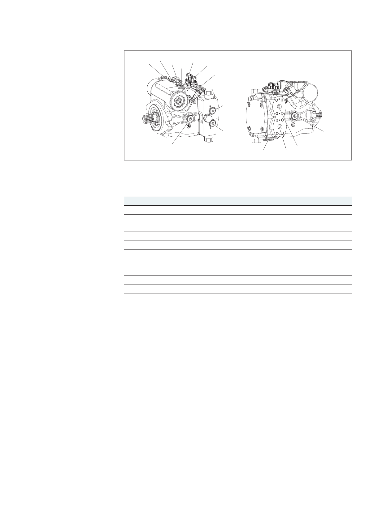
Installation | A10VG series 60 41/64
Port overview
P
S
X
1
R
T
M
B
M
X
2
2
A
F
e
F
a
G
S
B
A
T
1
Fig. 10: Port overview A10VG series 60
Table 8: Ports A10VG series 60
Ports
1)
p
max
[bar]
2)
State
3)
A, B Working port 470 O
S Suction port 5 O
T
1
T
2
Drain port 3 O
Drain port 3 X
4)
5)
5)
R Air bleed port 3 X
X
1, X2
Control pressure port 30 X
G Boost pressure port inlet 30 X
P
s
M
A, MB
F
a
F
e
The measuring system and thread size can be found in the installation drawing.
1)
2) Depending on the application, momentary pressure peaks can occur. Keep this in mind when
Pilot pressure port 30 X
Measuring port, pressure A, B 470 X
Boost pressure port inlet 30 X
Boost pressure port output 30 X
6)
7)
7)
selecting measuring devices and ttings.
3)
O=Must be connected (plugged on delivery)
X=Plugged (in normal operation)
4) Plugged for external boost pressure supply.
5) Depending on the installation position, T
or T2 must be connected (see chapter7.3
1
"Installation position" on page32).
6) Pressure sensor mounted or M
7) Must be connected for ltration in the pressure line.
, MB plugged.
A
Tightening torques
The following tightening torques apply:
• Fittings:
Observe the manufacturer's specications regarding the tightening torques of the
ttings used.
• Female threads in the axial piston unit:
The max. permissible tightening torques M
are the maximum values for the
G max
female threads and must not be exceeded. For values, see Table 9.
• Threaded plugs:
For the metallic threaded plugs supplied with the axial piston unit, the required
tightening torques of threaded plugs M
apply. For values, see Table 9.
V
RE 92760-01-B/2024-07-16, BoschRexrothAG
Page 42

42/64 A10VG series 60 | Installation
• Fixing screws:
For xing screws with metric ISOthreads according to DIN13 and/or ASMEB1.1
threads, we recommend checking the tightening torque in individual cases in
accordance with VDI2230.
In addition to the ports specied in Table 8 "Ports A10VG series 60eries 60"
on page41, axial piston units may have openings that are also closed with
athreaded plug. These plugs must not be opened on the customer side!
If you have opened the threaded plug accidentally, please contact your local
contact person to ensure safe re-closing of the plug. You can nd the address at
https://addresses.boschrexroth.com
Table 9: Tightening torques for female threads and threaded plugs
Ports
Standard Thread size
ISO 6149 M8×1 10Nm 7Nm 4 mm
M10×1 30Nm 15Nm 5 mm
M12×1.5 50Nm 25Nm 6 mm
M14×1.5 80Nm 45Nm 6 mm
M16×1.5 100Nm 55Nm 8 mm
M18×1.5 140Nm 70Nm 8 mm
M20×1.5 170Nm 80Nm 10 mm
M22×1.5 210Nm 100Nm 10 mm
M27×2 330Nm 170Nm 12 mm
M30×2 420Nm 215Nm 17 mm
M33×2 540Nm 310Nm 17 mm
M42×2 720Nm 330Nm 22 mm
M48×2 900Nm 420Nm 22 mm
ISO11926 5/16-24 UNF-2B 10Nm 7Nm 1/8 in
3/8-24 UNF-2B 20Nm 10Nm 5/32 in
7/16-20 UNF-2B 40Nm 18Nm 3/16 in
9/16-18 UNF-2B 80Nm 35Nm 1/4 in
3/4-16 UNF-2B 160Nm 70Nm 5/16 in
7/8-14 UNF-2B 240Nm 110Nm 3/8 in
1 1/16-12 UN-2B 360Nm 170Nm 9/16 in
1 5/16-12 UN-2B 540Nm 270Nm 5/8 in
1 5/8-12 UN-2B 960Nm 320Nm 3/4 in
1 7/8-12 UN-2B 1200Nm 390Nm 3/4 in
Maximum permissible
tightening torque of female
threads M
max
G
Required tightening
torque of threaded plugs M
WAF hexagon socket
of the threaded plug
V
BoschRexrothAG, RE 92760-01-B/2024-07-16
Page 43

Installation | A10VG series 60 43/64
Procedure
To connect the axial piston unit to the hydraulic system:
1. Remove the protective plugs and/or threaded plugs from the ports where the
connections must be made according to the hydraulic circuit diagram.
2. Make sure the sealing surfaces of the hydraulic ports and functional surfaces
are not damaged.
3. Use only clean hydraulic lines or ush them before installation.
(Observe chapter7.5 "Performing ushing cycle" on page44 when you
ush the hydraulic system.)
4. Connect the lines in accordance with the installation drawing and the machine
or system circuit diagram. Check that all ports are connected or plugged with
threaded plugs.
5. Properly tighten the ttings (observe tightening torques!). Mark all properly
tightened ttings, e.g.with apermanent marker.
6. Check all pipes and hose lines and every combination of connecting pieces,
couplings or connecting points with hoses or pipes to ensure they are in safe
working condition.
For relationship between direction of rotation and ow direction, see data sheet
92760.
7.4.9 Electrically connecting the axial piston unit
NOTICE
Negative effect on function due to incorrect plug-in connections!
Only the plug-in connections specied in the data sheet may be used for the
electrical connection.
▶ Observe the installation specications of the manufacturer of the plug-in
connection.
▶ Before commissioning, check whether the voltage in the power supply matches
the parameters in the data sheet 92760 and whether the total current to be
expected is less than or the same as the load capacity of the power supply.
▶ Only the dead weight (<1N) of the connection cable with a length of 150mm
is permitted to act on the plug-in connection. Other forces and vibrations are
not permissible. This can be realized e.g. by suspension of the cable on the
same vibration system.
▶ No additional sealants must be applied.
▶ The plug-in connections must only be plugged in and unplugged in the de-
energized state.
Short circuit due to penetrating hydraulic uid!
Fluid can penetrate the product and cause ashort circuit!
▶ Do not install axial piston units with electric components (e.g. electric
controls, sensors) in areservoir below the uid level (inside-reservoir
installation).
The machine/system manufacturer is responsible for electric control layout.
Electrically controlled axial piston units must be connected in accordance with the
electrical circuit diagram for the machine/system.
RE 92760-01-B/2024-07-16, BoschRexrothAG
Page 44

44/64 A10VG series 60 | Installation
Observe the parameters according to data sheet 92760, e.g.:
• Permissible voltage range
• Permissible current
• Correct pin assignment
• Recommended electrical control units
Exact details on the connector, type of protection and matching mating connector
can also be found in data sheet 92760. The mating connector is not included in the
scope of delivery.
Procedure
1. Switch off the power supply to the relevant machine/system component.
2. Electrically connect the axial piston unit (12 or 24 V). Before connecting,
check whether the connector protective covers (3) are off (see Fig. 9 "Removing
transport protection" on page38), and the connector and all seals are intact.
7.5 Performing ushing cycle
In order to remove foreign particles from the system, BoschRexroth recommends
aushing cycle for the hydraulic system before the rst commissioning. To avoid
internal contamination, do not include the axial piston unit in the ushing cycle.
Use an additional ushing unit to perform the ushing cycle. Follow the
instructions of the ushing unit's manufacturer for the exact procedure during
the ushing cycle.
BoschRexrothAG, RE 92760-01-B/2024-07-16
Page 45
Commissioning | A10VG series 60 45/64
8 Commissioning
To efciently operate the axial piston unit, it is advisable to calibrate the unit
via the electronic control in the application since each hydraulic component has
manufacturing tolerances that can also affect electronic control.
WARNING
Danger while working in the danger zone of amachine/system!
Danger to life, risk of injury or serious injury!
▶ Pay attention to and eliminate potential danger sources before commissioning
the axial piston unit.
▶ Make sure no one is in the danger zone of the machine/system.
▶ The emergency stop button for the machine/system must be within the
operator's reach.
▶ Always follow the instructions of the machine/system manufacturer during
commissioning.
CAUTION
Commissioning an incorrectly installed product!
Risk of injury and property damage!
▶ Make sure all electrical and hydraulic ports are connected or plugged.
▶ Commission only afully installed, fully functioning product with original
accessories from BoschRexroth.
8.1 Initial commissioning
During all commissioning work on the axial piston unit, observe the general
safety instructions and intended use detailed in chapter2 "Safety instructions"
on page9.
▶ Connect the pressure gauge for the boost pressure, working pressure,
case pressure and suction pressure to the specied measuring points on
the axial piston unit or in the hydraulic system to check the technical data
during initial operation.
▶ During commissioning, monitor the temperature of the hydraulic uid in the
reservoir to ensure that it lies within permissible viscosity limits.
8.1.1 Filling the axial piston unit
Professional lling and air bleeding is required to prevent damage to the axial
piston unit and to maintain proper function.
RE 92760-01-B/2024-07-16, BoschRexrothAG
Page 46

46/64 A10VG series 60 | Commissioning
Usually, the cleanliness level of commercial hydraulic uids is insufcient for
the requirements of our components. These hydraulic uids must be ltered
during lling using an appropriate lter system to minimize solid particle
contamination and water in the system.
Use only ahydraulic uid that corresponds to the following requirements:
You can nd details on the minimum requirements for hydraulic uids in Rexroth
data sheets 90220, 90221, 90222, and 90225. The titles of the data sheets can be
found in Table 1 "Required and supplementary documentation" on page5.
BoschRexroth evaluates hydraulic uids on the basis of the Fluid Rating
according to datasheet90235. For hydraulic uids which have been positively
evaluated in the Fluid Rating, please refer to data sheet 90245 "BoschRexroth
Fluid Rating List for Rexroth hydraulic components (pumps and motors)".
Selection of hydraulic uid shall make sure that the operating viscosity in the
operating temperature range is within the optimum range (ν
diagram in the data sheet 92760).
; see selection
opt
Procedure
To ensure the functional reliability of the axial piston unit, cleanliness level
20/18/15 according to at least ISO 4406 is required for the hydraulic uid.
At ahydraulic uid viscosity of less than 10 mm²/s (e.g.due to high temperatures
during short-term operation), acleanliness level of at least 19/17/14 according
to ISO 4406 is required. You can nd parameters on the permissible and optimal
viscosities and permissible temperatures in data sheet 92760.
Proceed as follows to ll the axial piston unit:
1. Place adrip tray under the axial piston unit to collect any hydraulic uid that
may leak.
NOTICE! Contaminated hydraulic uid!
The cleanliness levels of commercial hydraulic uids are usually insufcient for the
requirements of our components.
▶ Use asuitable lter system to lter hydraulic uids during lling to minimize
solid particle contamination and water in the hydraulic system.
2. Fill and air bleed the axial piston unit via the appropriate ports; see chapter7.3
"Installation position" on page32. Also ll the hydraulic lines of the system.
NOTICE! Risk of property damage due to inadequate lubrication!
Product can be damaged or destroyed!
▶ When using ashut-off valve in the suction line, make sure that the drive of the
axial piston unit can only be started when the shut-off valves are open.
▶ Dimension ashut-off valve in the suction line so that no inadmissible pressure
drop occurs in the suction area when the shut-off valve is open.
3. Make sure that the direction of rotation of the axial piston unit matches
the direction of rotation of the drive motor. The direction of rotation
of the axial piston unit is indicated on the name plate, see chapter5.4
"Product identication", Fig. 3:Name plate A10VG on page24.
BoschRexrothAG, RE 92760-01-B/2024-07-16
Page 47
Commissioning | A10VG series 60 47/64
4. Operate the axial piston pump at alow rotational speed (starter speed for
internal combustion engines and/or inching mode for electric motors) until the
hydraulic system is completely lled and air bled. To verify, drain the hydraulic
uid at the drain port until there are no bubbles in the uid.
8.1.2 Testing the hydraulic uid supply
The axial piston unit must always have asufcient supply of hydraulic uid.
For this reason, the supply of hydraulic uid must be ensured at the start of the
commissioning process.
When you test the hydraulic uid supply, constantly monitor noise development and
check the hydraulic uid level in the reservoir. If the axial piston unit becomes louder
(cavitation) or the leakage uid is discharged with bubbles, this is an indication that
the axial piston unit is not being sufciently supplied with hydraulic uid.
For information on troubleshooting, see chapter14 "Troubleshooting" on page56.
To test the hydraulic uid supply:
1. Allow the drive motor to run at the lowest rotational speed. The axial piston
unit should be operated without load. Pay attention to leaks and noises.
2. Check the axial piston unit's drain line during the test. The leakage should be
without bubbles.
3. Increase the load and check whether the working pressure rises as expected.
4. Perform aleak test to ensure the hydraulic system is sealed and can withstand
the max. pressure.
5. Check the suction pressure at portS of the axial piston pump at nominal
speed. Refer to data sheet 92760 for the permissible value.
6. Atmaximum working pressure, check the case pressure at portT
to data sheet 92760 for the permissible value.
or T2. Refer
1
8.1.3 Performing afunctional test
WARNING
Improperly connected axial piston unit!
Mixing up the ports will cause malfunctions (e.g.lift instead of lower) and could
endanger personnel and equipment!
▶ Before the functional test, check whether the piping specied in the hydraulic
circuit diagram has been installed.
Once you have tested the hydraulic uid supply, perform afunctional test of
the machine/system. The functional test must be performed according to the
instructions of the machine/system manufacturer.
The axial piston unit is tested for functional capability and performance before
delivery according to the technical data. During commissioning, make sure the axial
piston unit was installed in the machine/system as intended.
RE 92760-01-B/2024-07-16, BoschRexrothAG
Page 48

48/64 A10VG series 60 | Commissioning
▶ After starting the drive motor, check in particular the specied pressures,
e.g.working pressure and feed pressure.
▶ Check whether the case pressure is within the given specication.
▶ For optimum function and dynamics of the axial piston unit, acomplete lling
of the two stroking chambers X
By swiveling the swashplate several times during commissioning, this can
usually be ensured.
▶ Perform aleak test without and with load prior to normal operation.
▶ If necessary, remove the pressure gauge and plug the ports with the specied
threaded plugs.
8.2 Running-in phase
Property damage due to insufcient viscosity!
Elevated hydraulic uid temperature may excessively reduce viscosity and damage
the product!
▶ Monitor the operating temperature during the running-in phase,
e.g.by measuring the leakage temperature.
▶ Reduce the loading (pressure, rotational speed) of the axial piston unit if
unacceptable operating temperatures and/or viscosities occur.
▶ Excessively high operating temperatures indicate faults that have to be
analyzed and eliminated.
and X2 with hydraulic uid is required.
1
NOTICE
The bearings and sliding surfaces are subject to arunning-in phase. The increased
friction at the start of the running-in phase results in increased heat development
which decreases with increasing operating hours. The mechanical-hydraulic
efciency is also greater until the running-in phase of about 10 operating hours is
concluded.
To ensure that contamination in the hydraulic system does not damage the axial
piston unit, BoschRexroth recommends the following procedure after the runningin phase:
▶ After the running-in phase, have ahydraulic uid sample analyzed for the
required cleanliness level.
▶ Change the hydraulic uid if the required cleanliness level is not reached.
If alaboratory test is not carried out after the running-in phase, BoschRexroth
recommends changing the hydraulic uid.
8.3 Recommissioning after standstill
Depending on the installation conditions and ambient conditions, changes may
occur in the hydraulic system which make recommissioning necessary.
The following criteria may make recommissioning necessary:
• Air and/or water in the hydraulic system
• Old hydraulic uid
• Other contamination
▶ Before recommissioning, proceed as described in chapter8.1 "Initial
commissioning" on page45.
BoschRexrothAG, RE 92760-01-B/2024-07-16
Page 49

Operation | A10VG series 60 49/64
9 Operation
This product is acomponent which requires no settings or changes during
operation. For this reason, this chapterof the manual does not contain any
information on adjustment options. Use the product only within the performance
range specied in the technical data. The machine/system manufacturer is
responsible for proper project planning of the hydraulic system and its control.
RE 92760-01-B/2024-07-16, BoschRexrothAG
Page 50
50/64 A10VG series 60 | Maintenance and repair
10 Maintenance and repair
Overdue inspection and maintenance work!
Property damage!
▶ Perform the specied inspection and maintenance work at the intervals
described in this manual.
In pumps with intermediate ange and spacer versions, the design may cause
humidity to penetrate the seal area and cause corrosion. However, this has no
effect on the function and reliability of the pump.
10.1 Cleaning and care
NOTICE
NOTICE
Damage to seals and electrical system due to mechanical effects!
The jet of ahigh-pressure cleaner may damage the seals and electrical system of
the axial piston unit!
▶ Do not point ahigh-pressure cleaner at sensitive components, e.g.shaft seal,
electrical connections and components.
For cleaning and care of the axial piston unit, observe the following:
▶ Check whether all seals and plug-in connections are securely seated to ensure
no moisture can penetrate into the axial piston unit during cleaning.
▶ Use only water and, if necessary, amild cleaning agent to clean the axial piston
unit. Never use solvents or aggressive cleaning agents.
▶ Remove major external contamination and keep clean sensitive and important
components, such as solenoids, valves, indicators and sensors.
10.2 Inspection
In order for the axial piston unit to be reliable and long-lasting, BoschRexroth
recommends inspecting the hydraulic system and axial piston unit on aregular
basis, and documenting and archiving the following operating conditions:
BoschRexrothAG, RE 92760-01-B/2024-07-16
Page 51

Maintenance and repair | A10VG series 60 51/64
Table 10: Inspection schedule
Tasks to be performed Interval
Hydraulic
system
Axial piston
unit
Check hydraulic uid level in the reservoir. Daily
Perform hydraulic uid analysis: Viscosity, aging and
contamination
Check lter.
The replacement interval may vary depending on the
cleanliness of the hydraulic uid. We recommend using
acontamination indicator.
Check axial piston unit for leakage.
Early detection of hydraulic uid loss can help to nd
faults on the machine/system and rectify them. This is
why BoschRexroth recommends always keeping the
axial piston unit and system clean.
Check axial piston unit for unusual noise development. Daily
Check mounting elements for tight seating.
All fasteners have to be checked when the hydraulic
system is switched off, depressurized and cooled down.
Yearly or every
2000 operating
hours (whichever
occurs rst)
Yearly or every
1000 operating
hours (whichever
occurs rst)
Daily
Monthly
10.3 Maintenance
The axial piston unit is low-maintenance when used as intended.
The service life of the axial piston unit is heavily dependent on the quality of the
hydraulic uid. This is why we recommend changing the hydraulic uid at least
once per year or every 2000 operating hours (whichever occurs rst), or having
it analyzed by the hydraulic uid manufacturer or alaboratory to determine its
suitability for further use.
The service life of the axial piston unit is limited to the service life of the bearings
used if the permissible operating parameters are observed. You can ask your
local contact person about service life based on load cycle. You can nd their
contact information at
https://addresses.boschrexroth.com
Based on these parameters, amaintenance interval must be determined by the
system manufacturer for the replacement of the bearings and included in the
maintenance schedule of the hydraulic system.
RE 92760-01-B/2024-07-16, BoschRexrothAG
Page 52
52/64 A10VG series 60 | Maintenance and repair
10.4 Repair
BoschRexroth offers acomprehensive range of services for the repair of Rexroth
axial piston units.
Repairs on the axial piston unit and its assembled parts should only be performed
by service centers certied by BoschRexroth.
▶ Only use original spare parts from Rexroth to repair the Rexroth axial piston
units, otherwise the functional reliability of the axial piston unit cannot be
guaranteed, and the warranty will be voided.
For questions regarding repairs, contact your proper BoschRexroth service partner
or the service department of the manufacturer's plant of the axial piston unit;
see chapter10.5 "Spare parts" on page52.
10.5 Spare parts
Use of unsuitable spare parts!
Spare parts that do not meet the technical requirements specied by
BoschRexroth can cause injury and property damage!
▶ Only use original spare parts from Rexroth to repair the Rexroth axial piston
units, otherwise the functional reliability of the axial piston unit cannot be
guaranteed, and the warranty will be voided.
CAUTION
The spare parts lists for axial piston units are order-specic. When ordering spare
parts, specify the material and serial number of the axial piston unit as well as the
material numbers of the spare parts.
Address all questions regarding spare parts to your proper BoschRexroth Service
partner or the service department of the manufacturer's plant of the axial piston unit.
BoschRexrothAG
Glockeraustraße 2
89275 Elchingen, Germany
Hotline +49 9352 405060
Spare parts can be found online at www.boschrexroth.com/spc
For general inquiries, please contact your local contact person, you can nd the
address under
https://addresses.boschrexroth.com
BoschRexrothAG, RE 92760-01-B/2024-07-16
Page 53

Removal and replacement | A10VG series 60 53/64
11 Removal and replacement
11.1 Required tools
Removal can be performed using standard tools. No special tools are necessary.
11.2 Preparing for removal
1. Decommission the relevant machine/system part as described in the operating
instructions for the machine or system.
– Relieve pressure in the hydraulic system according to the specications of the
machine or system manufacturer.
– Make sure the relevant machine/system components are depressurized and
de-energized.
2. Secure the relevant machine/system part against restart.
11.3 Performing the removal
Proceed as follows to remove the axial piston unit:
1. Make sure you have the appropriate tools and wear personal protective
equipment.
2. Allow the axial piston unit to cool down until it can be removed without danger.
3. For below-reservoir installation, before removing the axial piston unit, seal the
connection to the reservoir and/or drain the reservoir.
4. Place adrip tray under the axial piston unit to collect any hydraulic uid that
may leak.
5. Disconnect the lines and collect the escaping hydraulic uid in the drip tray.
6. Remove the axial piston unit. Use asuitable lifting device.
7. Completely drain the axial piston unit.
8. Plug all openings.
11.4 Preparing the components for storage or further use
▶ Proceed as described in chapter6.2 "Storing the axial piston unit"
on page28.
RE 92760-01-B/2024-07-16, BoschRexrothAG
Page 54

54/64 A10VG series 60 | Disposal
12 Disposal
Careless disposal of the axial piston unit, the hydraulic uid and the packaging
material can result in environmental pollution.
Observe the following when disposing of the axial piston unit:
1. Completely drain the axial piston unit.
2. Dispose of the axial piston unit and packaging material in accordance with the
regulations in your country.
3. Dispose of the hydraulic uid in accordance with the regulations of your
country. Also observe the applicable safety data sheet for the hydraulic uid.
4. Disassemble the axial piston unit into its constituent parts for proper recycling.
5. For example, separate the parts into:
– Castings
– Steel
– Aluminum
– Non-ferrous metal
– Electronic waste
– Plastic
– Seals
BoschRexrothAG, RE 92760-01-B/2024-07-16
Page 55

Extension and conversion | A10VG series 60 55/64
13 Extension and conversion
Do not modify the axial piston unit and/or its assembled parts.
Changes to settings on the customer side should only be made using the
product-specic setting instructions.
The warranty from BoschRexroth only applies to the conguration as delivered.
Any modication or upgrade voids the warranty.
Setting screws are protected against unauthorized adjustment by tamper-proof
caps. Removal of the tamper-proof caps will void the warranty. If you need to
change the settings, please contact your local contact person. You can nd their
contact information under
https://addresses.boschrexroth.com
RE 92760-01-B/2024-07-16, BoschRexrothAG
Page 56

56/64 A10VG series 60 | Troubleshooting
14 Troubleshooting
The Table 11 is intended to support troubleshooting. This table is not exhaustive.
Issues may occur in practice that are not listed here.
Only authorized personnel may perform troubleshooting inside asafety area
designated by the machine manufacturer.
14.1 How to proceed for troubleshooting
▶ Perform troubleshooting if possible with reduced operating data
(e.g.slowly swinging in or out and slow pressure increase).
▶ Worksystematically and in a targeted manner, even when pressed for time.
Random, indiscriminate removal and changing of settings could make it
impossible to determine the original cause of the fault.
▶ First get ageneral idea of how your product functions in conjunction with the
entire system.
▶ Try to nd out whether or not the product was working properly in conjunction
with the entire system before the fault occurred.
▶ Try to determine any changes to the entire system in which the product is
installed:
– Have there been any changes to the application conditions or operating range
of the product?
– Has maintenance work recently been carried out? Is there an inspection or
maintenance log?
– Have any changes (e.g.upgrades) or repairs been made to the overall system
(machine/system, electrics, control) or to the product? If yes: What changes?
– Has the hydraulic uid been changed?
– Has the product or machine been used as intended?
– How does the malfunction appear?
▶ Try to get aclear idea of the cause of the fault. Directly ask the (machine) operator.
▶ Document the work carried out.
▶ If the fault cannot be corrected, please refer to one of the contact addresses at:
https://addresses.boschrexroth.com.
BoschRexrothAG, RE 92760-01-B/2024-07-16
Page 57

Troubleshooting | A10VG series 60 57/64
14.2 Malfunction table
Table 11: Axial piston unit malfunction table
Malfunction Possible cause Remedy
Unusual noises Insufcient air bleeding of the hydraulic
system
Fill the axial piston unit, suction line for the
hydraulic pump and the reservoir
Completely air bleed the axial piston unit and
hydraulic system
Check correct installation position
Insufcient suction conditions,
e.g.,insufcient dimensioning of the suction
line, viscosity of the hydraulic uid too high,
suction height too high, suction pressure
too low, foreign particles in the suction line,
suction lter too small or blocked, etc.
Drive speed too high Machine/system manufacturer:
Wrong direction of rotation Machine/system manufacturer:
Improper mounting of the axial piston unit Check the mounting of the axial piston unit
Improper mounting of assembled parts,
hydraulic lines or improper installation of the
coupling
Resonances due to adefective or unsuitable
elastic coupling
Oscillate pressure relief valves and pressure
control valves in the axial piston unit
(boost-pressure relief valve, high-pressure
relief valve, pressure reducing valve)
Mechanical damage to the axial piston unit
(e.g.bearing damage)
Machine/system manufacturer:
Check the system, e.g.optimize inlet
conditions, use suitablehydraulic uid
Fill the suction line with hydraulic uid
Remove foreign particles from the suction line
Check the lter system and change the lter as
necessary
Reduce drive speed
Check correct direction of rotation,
seechapter7.4.1 "Preparation" on page34
according to the specications of the machine/
system manufacturer – observe tightening
torques
Fasten assembled parts according to the
parameters provided by the coupling tting
manufacturer
Check the specication of the elastic coupling
and/or exchange defective or worn coupling
Air bleed the axial piston unit and hydraulic
system
Contact BoschRexroth Service:
Optimize the setting of the pressure limitation
and pressure control valve
Replace axial piston unit
Contact BoschRexroth Service
Increased, unusual vibration Bearings worn Contact BoschRexroth Service
RE 92760-01-B/2024-07-16, BoschRexrothAG
Page 58

58/64 A10VG series 60 | Troubleshooting
Table 11: Axial piston unit malfunction table
Malfunction Possible cause Remedy
No or insufcient ow Insufcient air bleeding of the
hydraulic system
Faulty mechanical drive
(e.g.defective coupling)
Drive speed too low Contact machine/system manufacturer
Fill the axial piston unit, suction line for the
hydraulic pump and the reservoir
Completely air bleed the axial piston unit and
hydraulic system
Contact machine/system manufacturer
Insufcient suction conditions,
e.g.,insufcient dimensioning of the suction
line, viscosity of the hydraulic uid too high,
suction height too high, suction pressure
too low, foreign particles in the suction line,
suction lter too small or blocked, etc.
Hydraulic uid not in optimal viscosity range Machine/system manufacturer:
Insufcient boost pressure Check boost pressure
Insufcient pilot pressure or control pressure Check pilot pressure or control pressure
Malfunction of the control device or controller
of the axial piston unit
Control of the control device defective Check control (contact machine/system
Wear or mechanical damage to the axial
piston unit
Machine/system manufacturer: Check the
system, e.g.optimize inlet conditions, use
suitablehydraulic uid
Fill the suction line with hydraulic uid
Remove foreign particles from the suction line
Check the lter system and change the lter as
necessary
Check temperature range and use suitable
hydraulic uid
Contact BoschRexroth Service
Contact BoschRexroth Service
Contact BoschRexroth Service
manufacturer or BoschRexroth Service)
Replace axial piston unit
Contact BoschRexroth Service
BoschRexrothAG, RE 92760-01-B/2024-07-16
Page 59

Troubleshooting | A10VG series 60 59/64
Table 11: Axial piston unit malfunction table
Malfunction Possible cause Remedy
No or insufcient pressure Insufcient air bleeding of the hydraulic
system
Fill the axial piston unit, suction line for the
hydraulic pump and the reservoir
Completely air bleed the axial piston unit and
hydraulic system
Check correct installation position
Faulty mechanical drive
(e.g.defective coupling)
Drive power too low Contact machine/system manufacturer
Insufcient suction conditions,
e.g.,insufcient dimensioning of the suction
line, viscosity of the hydraulic uid too high,
suction height too high, suction pressure
too low, foreign particles in the suction line,
suction lter too small or blocked, etc.
Hydraulic uid not in optimal viscosity range Machine/system manufacturer:
Insufcient boost pressure Check boost pressure
Insufcient pilot pressure or control pressure Check pilot pressure or control pressure
Malfunction of the control device or controller
of the axial piston unit
Control of the control device defective Check control (contact machine/system
Wear or mechanical damage to the axial
piston unit
Contact machine/system manufacturer
Machine/system manufacturer:
Check the system, e.g.optimize inlet
conditions, use suitablehydraulic uid
Fill the suction line with hydraulic uid
Remove foreign particles from the suction line
Check the lter system and change the lter as
necessary
Check temperature range and use suitable
hydraulic uid
Contact BoschRexroth Service
Contact BoschRexroth Service
Contact BoschRexroth Service
manufacturer or BoschRexroth Service)
Replace axial piston unit
Contact BoschRexroth Service
Output unit defective (e.g.hydraulic motor or
cylinder)
Contact machine/system manufacturer
RE 92760-01-B/2024-07-16, BoschRexrothAG
Page 60

60/64 A10VG series 60 | Troubleshooting
Table 11: Axial piston unit malfunction table
Malfunction Possible cause Remedy
Pressure/ow uctuations/
instabilities
Insufcient air bleeding of the
hydraulic system
Fill the axial piston unit, suction line for the
hydraulic pump and the reservoir
Completely air bleed the axial piston unit and
hydraulic system
Check correct installation position
Excessively high temperature of
hydraulic uid and housing
Insufcient suction conditions,
e.g.,insufcient dimensioning of the suction
line, viscosity of the hydraulic uid too high,
suction height too high, suction pressure
too low, foreign particles in the suction line,
suction lter too small or blocked, etc.
Oscillate pressure relief valves and pressure
control valves in the axial piston unit
(boost-pressure relief valve, high-pressure
relief valve, pressure reducing valve)
Unstable control signal Contact machine/system manufacturer or
Malfunction in the control devices or the
controller
Excessively high inlet temperature at the axial
piston unit
Wrong setting and/or malfunction of the
pressure limitation and pressure control
valves (e.g.high-pressure relief valve)
Machine/system manufacturer:
Check the system, e.g.optimize inlet
conditions, use suitablehydraulic uid
Fill the suction line with hydraulic uid
Remove foreign particles from the suction line
Check the lter system and change the lter as
necessary
Air bleed the axial piston unit and hydraulic
system
Contact BoschRexroth Service
BoschRexroth Service
Contact BoschRexroth Service
Machine/system manufacturer: Inspect system,
e.g. malfunction in the cooler, insufcient
hydraulic uid in the reservoir
Optimize the adjustment of the pressure
limitation and pressure control valves of the
axial piston unit and the pressure safeguarding
in the hydraulic system
Contact BoschRexroth Service
Contact machine/system manufacturer
Flushing ow of the ushing valve too low Contact BoschRexroth Service
Axial piston unit worn Replace axial piston unit;
contact BoschRexroth Service
BoschRexrothAG, RE 92760-01-B/2024-07-16
Page 61
Technical data | A10VG series 60 61/64
15 Technical data
The permissible technical data for your axial piston unit can be found in the data
sheet92760.
The data sheet can be found in the Download Center:
www.boschrexroth.com/ics/ref/media/92760
Additional information can be found in the Rexroth store:
www.boschrexroth.com/p-A10VG-60
Order-related technical data for your axial piston unit can be found in the order
conrmation.
RE 92760-01-B/2024-07-16, BoschRexrothAG
Page 62

62/64 A10VG series 60 | Alphabetical index
16 Alphabetical index
A
Abbreviations .................................. 8
Above-reservoir installation .......... 34
Assembly ...................................... 34
B
Below-reservoir installation .......... 33
Boost pump .................................. 21
C
Care ............................................. 50
Circuit
Closed ....................................... 20
Cleaning ....................................... 50
Commissioning ............................. 45
Initial ......................................... 45
Connecting
Electric ....................................... 43
Hydraulic .................................... 39
Control ......................................... 20
Conversion ................................... 55
Corrosion protection .................... 28
Corrosion protection lm .............. 28
D
Designations ................................... 7
Dimensions ..............................25
Direction of rotation ..................... 35
Disposal ....................................... 54
E
External boost pressure supply..... 21
Eye bolt ........................................ 26
F
Filling ........................................... 45
Flushing cycle ............................... 44
Functional test .............................. 47
I
Identication ................................ 24
Inspection .................................... 50
Installation ................................... 30
Completion ................................ 37
General instructions ................... 35
On agearbox .............................. 37
On gearbox ................................ 37
Preparation ................................ 34
With cardan shaft ....................... 37
With coupling ............................. 36
Installation conditions .................. 30
Installation position
Above-reservoir installation ........ 34
Below-reservoir installation ........ 33
Intended use .................................. 9
L
Lifting devices .............................. 25
Lifting strap .................................. 27
M
Maintenance ............................50, 51
Malfunction table ......................... 57
N
Name plate ................................... 24
Notes
General ...................................... 35
O
Operation ..................................... 49
35
P
Performance description ............... 20
Port overview ............................... 41
Product description ...................... 20
Property damage .......................... 16
Pump function .............................. 20
,
Q
Qualication ................................. 10
R
Recommissioning
After standstill ........................... 48
Removal ........................................ 53
Performing ................................. 53
Preparing ................................... 53
Repair ........................................... 52
Replacement ................................. 53
Required documentation ................ 5
Running-in phase .......................... 48
BoschRexrothAG, RE 92760-01-B/2024-07-16
Page 63

Alphabetical index | A10VG series 60 63/64
S
Safety instructions .......................... 9
General ...................................... 11
Product-specic ......................... 12
Signal word .................................. 6
Scope of delivery .......................... 19
Spare parts ................................... 52
,
Storage ....................................25
Storage time ................................. 28
Symbols ......................................... 7
28
T
Technical data............................... 61
Tightening torques ........................ 41
Tools............................................. 53
Transport ...................................... 25
By hand ...................................... 25
With eye bolt .............................. 26
With lifting strap ........................ 27
Transporting ................................. 25
Transport protection ..................... 38
Troubleshooting ............................ 56
U
Unpacking ..................................... 30
W
Warranty ............................ 18, 38, 55
Weight .......................................... 25
RE 92760-01-B/2024-07-16, BoschRexrothAG
Page 64

BoschRexrothAG
Glockeraustraße 2
89275 Elchingen
Germany
Phone +49 7308 82-0
[email protected]
www.boschrexroth.com
Your local contact person can be found at:
https://addresses.boschrexroth.com
Subject to change
RE 92760-01-B/2024-07-16
 Loading...