


Identifikationssystem ID 15 Identification system ID 15 Système d’identification ID 15 Sistema di identificazione ID 15 Sistema de identificación ID 15 Sistema de Identificação ID 15
3 842 536 035 (2006.11) DE+E N+FR+IT+E S+PT
The Drive & Control Company |
|
|
DE |
|
3 842 406 960 |
|
|
|
EN |
|
|
|
FR |
|
3 842 535 440, |
ID 15/MDT14 |
( 20) |
|
|
3 842 535 442, |
ID 15/MDT23 |
( 16, 17, 18, 22) |
|
|
3 842 535 443, |
ID 15/MDT22 |
( 21) |
|
IT |
3 842 535 911, |
ID 15/MDT13 |
( 16) |
|
|
3 842 535 912, |
ID 15/ MS4 |
( 19) |
|
E S |
3 842 535 913, |
ID 15/ MS3 |
( 19) |
536035-11.eps |
|
|
||||
3 842 535 916, |
ID 15/MDT11 |
( 12) |
|
PT |
3 842 535 917, |
ID 15/ MS2 |
( 21) |
|
|
3 842 535 918, |
ID 15/ MS5 |
( 18) |
|
|
3 842 535 919, |
ID 15/MDT21 |
( 12, 13) |
|
|
3 842 535 920, |
ID 15/ MS1 |
( 10, 14) |
|
|
3 842 536 612, |
ID 15/ MDT12-80 |
( 20) |
|
|
3 842 536 613, |
ID 15/ MDT12-120 |
( 20) |
|
|
3 842 536 614, |
ID 15/ MDT12-160 |
( 20) |
|
|
3 842 537 885 |
|
( 11, 15) |
|
|
|
536035-00.eps |
|
|
|
2 |
Bosch Rexroth AG |
|
ID 15 |
|
|
3 842 536 035 (2006.11) |
|
|
|||||
|
|
|
|
|
|
|
|
|
|
|
|
||
Diese Montageanleitung |
These assembly instructions |
Cette instruction de montage |
||||
– gilt für Geräte der Typen: |
– apply to device types: |
– est valable pour les appareils des |
||||
|
- Schreib-Lese-Kopf I D 15/SLK |
- Read/write head I D 15/SLK |
types : |
|
||
|
- Mobiler Datenträger I D 15/MDT |
- Mobile data t ag ID 15/MDT |
- tête d’écriture-lecture ID 15/SLK |
|||
– richtet sich an fachkundige Personen |
– are meant for qualified personnel |
- support de données mobile |
||||
|
im Sinne der E MVund der |
trained in EMC and the low volt age |
ID 15/MDT |
|
||
|
Niederspannungs-Richtlinie. |
guidelines |
– s’adresse aux personnes compétentes |
|||
– ist Bestandteil des Produktes. Sie |
– are a part of the product. They contain |
selon la directive CEM et de basse |
||||
|
enthält Angaben zum korrekten |
information on how to use this product |
tension. |
|
||
|
Umgang mit dem Produkt. Lesen Sie |
correctly. Read them before use, so |
– est un composant du produit. Elle |
|||
|
sie vor dem Einsatz, damit Sie mit |
that you are familiar with the |
contient des indications quant au |
|||
|
Einsatzbedingungen, Installation und |
conditions, installation and operation. |
maniement correct du produit. Avant |
|||
|
Betrieb vertraut werden. Befolgen Sie |
Follow the safety instructions. |
utilisation il est conseillé de la lire |
|||
|
die Sicherheitshinweise. |
|
attentivement, afin de prendre |
|||
|
|
|
connaissance des conditions |
|||
Bestimmungsgemäße Verwendung |
d’utilisation, de l’installation et du |
|||||
fonctionnement. Il est indispensable de |
||||||
Intended use |
suivre les conseils de sécurité. |
|
|
Utilisation conforme |
|
Die bestimmungsgemäße Verwendung des Sc hreib-Lese-Kopfes I D 15/SLK ist die Übertragung von Daten von und zum mobilen Datenträgern ID 15/MDT.
Der Schreib-Lese-Kopf I D 15/SLK wandelt die empfangenen Daten in digital codierte Werte und stellt die Werte der AS -i Steuerungsebene zur Verfügung
( AS-i Master, C ontroller oder Host).
Einsatzbereiche sind z.B.:
–Materialfluss-Steuerung und -Kontrolle in Fertigungslinien
–Lagermanagement durch automatische Lagergut-Erkennung
–Behältermanagement, Kommissionierung und Warenverfolgung .
The read/write head I D 15/SLK is used to transfer data to and from mobile data tags I D 15/MDT.
The read/write head I D 15/SLK converts the received data into digitally coded values and provides the values to the AS-i control level (AS-i master, controller, or host).
Areas of operation are e.g.:
–material flow control and monitoring of production lines
–warehouse management with automatic recognition of goods
–container management, commissioning and tracking goods.
L’utilis ation conforme de la tête d’écriture-lecture ID 15/SLK est la transmission de données de et vers le support de données mobile ID 15/MDT.
La tête d’écriture-lecture ID 15/SLK transforme les données reçues en valeurs numériques codées et les met à disposition du niveau de commande AS-i (maître AS-i, Controller ou Host).
Les domaines d’utilisation sont par ex. :
–commande et contrôle du flux de matériaux dans les chaînes de production
–management des entrepôts grâce à la reconnaissance automatique des biens de stockage
–management des conteneurs, préparation des commandes et suivi des produits.
Sicherheitshinweise Safety instructions Conseils de sécurité
Allgemeines
Befolgen Sie die Angaben in dieser Anleitung. Nichtbeachten der Hinweise, Verwendung außerhalb der bestimmungsgemäßen Verwendung, falsc he Installation oder Handhabung können Beeinträchtigungen der Sicherheit von Menschen und Anlagen zur Folge haben. Bei Schäden, die aus nicht bestimmungsgemäßer Verwendung und aus eigenmächtigen, in dieser Anleitung nicht vorgesehenen Eingriffen entstehen, erlischt jeglicher Gewährleistungsund Haftungsanspruch gegenüber dem Hersteller.
General
Follow the information in these instructions. Ignoring the instructions, unintended use, incorrect installation or handling could affect the safety of personnel and systems. In no event can the manufacturer accept warranty or liability claims for damages arising from improper use of the appliance or from intervention in the appliance other than that described in this instruction manual.
Généralités
Suivre les indications dans cette instruction. Le non respect des conseils, l’utilisation en dehors des domaines d’utilisation indiqués, une fausse installation ou manipulation peuvent entraîner une diminution de la sécurité des hommes et des installations. Le fabricant décline toute responsabilité et exclut toute réclamation concernant les dommages dus à une utilisation non conforme ou suite à des modifications effectuées sans autorisation et non prévues ci-contre.

3 842 536 035 (2006.11) |
|
ID 15 |
Bosch Rexroth AG |
3 |
|
||||
|
|
|
|
|
Einbau und Anschluss müssen den gültigen nationalen und internationalen Normen entsprechen. Die Verantwortung trägt derjenige, der das Gerät installiert.
Das Gerät darf nur von einer Elektrofachkraft eingebaut, angeschlossen und in Betrieb gesetzt werden, da die sichere Funktion des Gerätes und der Anlage nur bei ordnungsgemäßer Installation gewährleistet ist.
Schalten Sie das Gerät extern spannungsfrei, bevor Sie irgendwelche Arbeiten an ihm vornehmen.
Das Gerät muss zum Betrieb gemäß den Kriterien für sichere Kleinspannung (SELV) mit einer ex ternen Gleichspannung (26,5-31,6 V DC) versorgt werden.
Das Gerät ist gemäß der Spezifikationen in einem weiten Umgebungstemperaturbereich betreibbar. Aufgrund der zusätzlichen Eigenerwärmung kann es an den Gehäusewandungen beim Berühren in heißer Umgebung zu hohen wahrnehmbaren Temperaturen kommen.
Bei Fehlfunktion des Gerätes oder bei Unklarheiten setzen Sie sich bitte mit dem Hersteller in Verbindung. Eingriffe in das Gerät können schwerwiegende Beeinträchtigungen der Sicherheit von Menschen und Anlagen zur Folge haben. Eingriffe in das Gerät sind deshalb nicht zulässig und führen zu Haftungsund Gewährleistungsauschluss.
Explosive Stoffe
Der Schreib-Lese-Kopf I D 15/SLK ist ein Funkgerät. Funkgeräte dürfen generell nicht in der Nähe von Tankstellen, Kraftstoffdepots, Chemiewerken oder Sprengarbeiten benutzt werden. Transportieren und lagern Sie keine entflammbaren Gase, Flüssigkeiten oder explosive Stoffe im Bereich des Gerätes.
Elektronische Geräte
Der Betrieb kann die Funktionsfähigkeit von nicht ordnungsgemäß geschirmten elektronischen Geräten beeinträchtigen. Schalten Sie das Gerät in der Nähe medizinischer Geräte aus. Bitte informieren Sie sich bei Störungen ggf. beim Hersteller des jeweiligen Gerätes.
Installation and connection must be made in accordance with the applicable national and international standards. The person who installs the device is responsible for this.
The device may only be installed, connected and commissioned by qualified electrical personnel, since safe operation of the device and system can only be guaranteed with proper installation.
Disconnect the device from the external voltage before carrying out any work.
The device must be externally supplied with direct voltage (26.5-31.6 V DC) for operation according to the criteria for safe extra-low volt age (SELV) operation.
The device is capable of operation within a broad ambient temperature range according to the specifications. Due to the additional heat it generates, the housing can reach a noticeably high temperature in hot environments.
If the device is faulty or anything in these instructions is unclear, contact the manufacturer. Modifications to the device could seriously affect the safety of personnel and systems. Interventions in the device are therefore not allowed and will lead to exemption from liability and the warranty.
Le montage et le branchement doivent correspondre aux normes nationales et internationales valables. La personne installant l’appareil est le seul responsable.
L’appareil doit uniquement être monté, branché et mis en marche par une personne qualifiée en électronique, le fonctionnement sûr de l’appareil et de l’installation n’étant garanti uniquement lors d’une installation conforme.
Avant toute manipulation, mettre l’appareil hors tension externe.
Pour le fonctionnement, l’appareil doit être alimenté en tension continue externe (26,5-31,6 V C C) selon les critères pour une tension de protection (SELV).
Selon les spécifications, l’appareil fonctionne dans une large plage de températures ambiantes. Suite au rechauffement propre supplémentaire, des températures élevées peuvent être ressenties sur les parois du boîtier lors d’un contact dans un environnement chaud.
Lors d’un fonctionnement erroné de l’appareil ou lors d’incertitudes, contacter le fabricant. Des modifications de l’appareil peuvent entraîner une diminution importante de la sécurité des hommes et des installations et ne sont en conséquence pas autorisées. Le fabricant décline toute responsabilité et exclut toute réclamation y résultant.
DE EN FR
IT
E S PT
Explosive materials
The read/write head I D 15/SLK is a radio transmitting device. The use of radio transmitting devices is generally prohibited near gas stations, fuel depots, chemical plants or blasting sites. Do not transport or store flammable gases, liquids or explosive materials near the device.
Electronic devices
Operation can influence the proper function of electronic devices that have not been properly shielded. Turn the device off near medical devices. Contact the manufacturer of the respective device if there are any faults.
Matières explosives
La tête d’écriture-lecture ID15/SLK est un appareil radio. Les appareils radio ne doivent en général pas être utilisés à proximité de stations-service, dépots de carburant, usines de chimie ou des travaux à l’explosif. Ne pas transporter et stocker de gaz inflammables, de liquides ou de matières explosives près de l’appareil.
Appareils électroniques
Le fonctionnement peut diminuer le bon fonctionnement des appareils électroniques qui ne sont pas blindés correctement. Éteindre l’appareil quand il se trouve près d’appareils médicaux. Lors d’interférences, s’informer le cas échéant chez le fabricant de l’appareil concerné.
4 |
Bosch Rexroth AG |
ID 15 |
|
3 842 536 035 (2006.11) |
|
||||
|
|
|
|
|
Funkanlagenzulassung
Radio transmitter license
Homologation de l’installation radiotélégraphique
Kennzeichnung nach R&TTE (Radio Equipment and Telecommunications Terminal Equipment and the mutual recognition of their conformity); EC-Identifikationsnummer: 


Funk zulassung nach E N 300330.
Marking according to R&TTE (Radio Equipment and Telecommunications Terminal Equipment and the mutual recognition of their conformity);
EC I D number:
Radio transmitter license according to EN 300330.
FCC Registration
This device complies with Part 15
of the FCC Rules and with RSS -210
of Industry Canada. Operation is subject to the following two conditions.
(1)this device my not cause harmful interference, and
(2)this device must accept any interference received, including interference that may cause undesired operation.
Warning: Changes or modifications made to this equipment not expressly appoved by
Bosch Rexroth AG
may void the FCC authorization to operate this equipment.
Identification selon R&TTE (Radio Equipment and Telecommunications Terminal Equipment and the mutual recognition of their conformity) ; Numéro d’ident. EC : 


Homologation radiotélégraphique selon EN 300330.
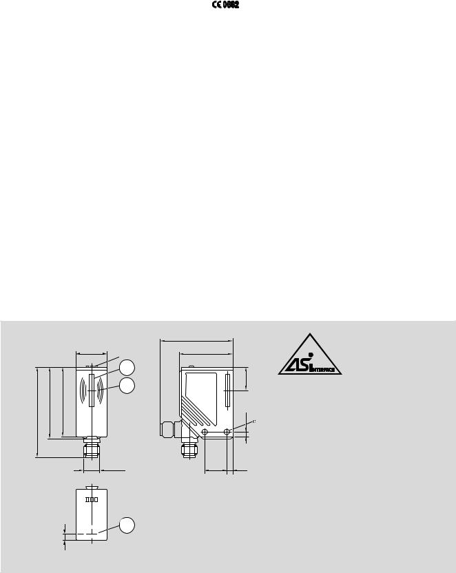
Anlieferzustand/Lieferumfang/Abmessungen Delivery condition/scope of delivery/dimensions État de livraison/fourniture/dimensions
|
|
|
56 |
|
|
24 |
41 |
|
|
|
LED |
|
|
|
1 |
|
|
|
17 |
|
|
|
2 |
70 |
55 |
53,5 |
3,7 |
M12x1 |
17 |
4,5 |
536035-11.eps
1: integrierte Antenne 1: Integrated antenna
4,2 1: Antenne intégrée
2: Positioniermarke für M DT ( Antennenmitte)
2: Positioning mark for M DT (center of antenna ) 2: Marquage de positionnement pour MDT
(centre de l’antenne)
2
5
536035-12.eps
3 842 536 035 (2006.11) |
|
ID 15 |
Bosch Rexroth AG |
5 |
|
||||
|
|
|
|
|
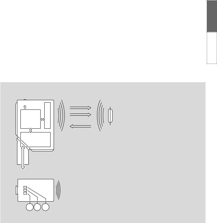
Funktionsweise und Anzeigeelemente Function and display elements Fonctionnement et éléments d’affichage
Die Datenträger ID 15/MDT werden passiv betrieben (ohne Batterie).
Die zum Betrieb notwendige Energie wird vom I D 15/SLK aufgebracht.
Das physikalische Prinzip der Energieübertragung beruht auf der induktiven Kopplung. Die integrierte Antennenspule des ID 15/SLK erzeugt ein magnetisches Feld, das teilweise die Antennenspule des I D 15/MDT durchdringt. Durch Induktion wird dort eine Spannung erzeugt, die den I D 15/MDT mit Energie versorgt.
Die Sendefrequenz beträgt 125 kHz. Im Wirkungskreis des ID 15/SLK dürfen deshalb keine anderen 125 kHz
emmitierenden Geräte betrieben werden, da dies zu Übertragungsfehlern führen kann!
Die Anzeigeelemente auf der Oberseite des ID 15/SLK zeigen die Betriebszustände an.
The dat a tag ID 15/MDT is operated passively (without a battery). The energy necessary for operation is provided by the I D 15/SLK.
The physical principle of the energy transfer is based on an inductive connection. The integrated antenna coil in the ID 15/SLK generates a magnetic field, which partially penetrates the antenna coil in the I D 15/MDT. A voltage is generated through induction, which supplies the I D 15/MDT with energy.
The transmitter frequency is 125 kHz. No other devices emitting 125 kHz may be operated within the range of influence of the I D 15/SLK, as this could lead to transmission errors!
The display elements on the top of the I D 15/SLK show the operating status.
Les supports de données ID 15/MDT fonctionnent de manière passive (sans batterie).
L’énergie nécessaire au fonctionnement est fournie par le ID 15/SLK.
Le principe physique de la transmission d’énergie est basé sur le couplage inductif. La bobine-antenne intégrée du ID 15/SLK génère un champ magnétique qui pénètre en partie la bobine-antenne du ID 15/MDT. Une tension qui alimente le ID 15/MDT en tension y est générée par induction.
La fréquence d’émission est de 125 kHz . Pour éviter des erreurs de transmission, aucun autre appareil avec une émission de 125 kHz ne doit se trouver dans la sphère d’action du ID 15/SLK !
Les éléments d’affichage situés sur le dessus du ID 15/SLK affichent les états de fonctionnement.
DE EN FR
IT
E S PT
|
|
I D 15/SLK |
ID 15/ MDT |
||
|
|
|
|
|
|
|
|
|
|
|
|
|
|
|
|
|
|
|
|
|
|
|
|
|
|
|
|
|
|
|
grün |
EI N |
Betriebsspannung OK |
1 |
Green ON |
Operating voltage OK |
|
|
Vert |
allumé |
Tension de service O K |
|
gelb |
EI N |
I D 15/MDT gelesen |
2 |
Yellow |
ON |
I D 15/MDT read |
|
Jaune |
allumé |
I D 15/MDT lu |
|
rot |
EI N |
AS-i Busfehler |
3 Red |
ON |
AS-i bus error |
|
|
Rouge |
allumé |
Erreur bus AS-i |
1 2 3
536035-13.eps
6 |
Bosch Rexroth AG |
ID 15 |
|
3 842 536 035 (2006.11) |
|
||||
|
|
|
|
|
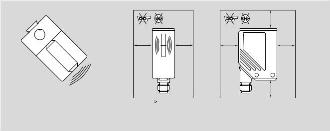
Spannungsversorgung Power supply Alimentation en tension
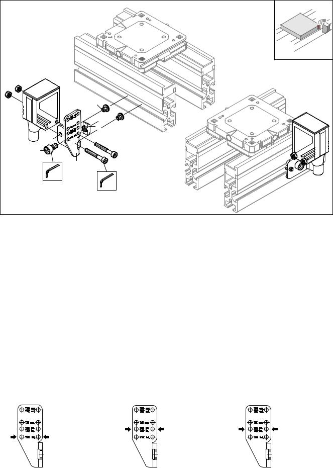
I D 15/SLK über die M12-Steckver- bindung mit dem AS-i-Netz verbinden. Die Spannungsversorgung erfolgt aus dem AS-i-Netz. Für sichere Datenübertragung beim Verlegen von Kabeln einen allseitigen Freiraum (a > 100 mm) beachten!
Connect the ID 15/SLK to the A S-i network via the M12 connector. The power supply comes from the AS-i network. For secure data transmission, keep a free area (a > 100 mm) on all sides when laying cables!
Connecter le ID 15/SLK avec le réseau AS-i via le connecteur enfichable M12. L’aliment ation en tension se fait par le réseau AS-i. Pour une transmission des données sûre lors de la pose des câbles, respecter un espace libre de tous les côtés (a > 100 mm ) !
a
2 
 1
1
3 
 4
4
a |
a |
a |
a |
536035-14.eps
a
1: AS-i + |
a 100 mm |
a > 100 mm |
3: AS-i – |
|
|
536035-15.eps |
|
Der Schreib-Lese-Kopf ID 15/SLK im AS-i Netzwerk
The read/write head ID 15/SLK in the AS-i network
La tête d’écriture-lecture ID 15/SLK dans le réseau AS-i
Grundeinstellung
Basic settings
Règlement de base
|
|
|
|
|
|
|
Parameter |
Wert |
Parameters |
Value |
Paramètres |
Valeur |
|
I /O C ode [hex] |
7 |
I/O code [ hex] |
7 |
Code E /S [ hex] |
|
7 |
I D Code [hex ] |
4 |
ID code [hex ] |
4 |
Code ID [hex ] |
|
4 |
Ex tended I D2 Code [hex ] |
C |
Extended I D2 code [hex ] |
C |
Code ID2 élargi [hex ] |
|
C |
I D1 Code für Codewert [hex ] |
F |
ID1 code for code value [hex ] |
F |
Code ID1 pour valeur de code [hex ] |
F |
|
Slave-Adresse (Werkseinstellung) |
0 |
Slave address (factory setting) |
0 |
Adresse d’esclave (réglage d’usine) |
0 |
|

3 842 536 035 (2006.11) |
|
ID 15 |
Bosch Rexroth AG |
7 |
|
||||
|
|
|
|
|
Adressierung
Addressing
Adressage
Der ID 15/SLK wird adressiert mit einem Adressiergerät, dem Master oder mit der AS-i-Software des Hosts (die Komponenten müssen AS-i Version 2.1 unterstützen).
Zulässiger Adressbereich: 1-31. Detaillierte Informationen hierzu finden Sie im Anwenderhandbuch ID 15,
3 842 536 511. www.boschrexroth.de/...
Analogwert-Repräsentation Analog value representation
Représentation de la valeur analogique
Für das A S-Interface ist der ID 15/SLK ein Analogslave mit Übertragungsprotokoll nach Profil 7.4. Arbeitet der Master mit der AS-i Version 3.0, erkennt er den ID 15/SLK automatisch und unterstützt das Profil 7.4.
Im Bereich der Analogwertübertragung sind die Profile 7.3 und 7.4 identisch.
Belegung der Datenbits
Assignment of the data bits
Affectations des bits utiles
The I D 15/SLK is addressed with an addressing device, the master, or with the host’s AS-i software (the components must support AS-i version 2.1).
Permissible address range: 1-31. Detailed information on this can be found in the ID 15 user manual, 3 842 536 511. www.boschrexroth.de/...
The I D 15/SLK is an analog slave with transmission protocol according to profile 7.4 for the AS interface. If the master works with AS-i version 3.0, it automatically recognizes the I D 15/SLK and supports profile 7.4.
Profiles 7.3 and 7.4 are identical in the analog value transmission range.
Le ID 15/SLK est adressé avec un appareil d’adressage, le maître ou avec le logiciel AS-i du Host (les composants doivent supporter la version AS-i 2.1). Zone d’adresse autorisée : 1-31.
Pour de plus amples informations, voir le manuel de l’utilisateur I D15,
3 842 536 511. www.boschrexroth.de/...
Pour l’interface AS, le ID 15/SLK est un esclave analogique avec protocole de transmission selon le profil 7.4. Si le maître travaille avec la version AS-i 3.0, il reconnaît automatiquement le ID 15/SLK et supporte le profil 7.4.
Dans le domaine da la transmission des valeurs analogiques, les profils 7.3 et 7.4 sont identiques.
DE EN FR
IT
E S PT
|
|
Pro Übertragungszyklus werden |
The following data is transferred in data |
folgende Daten in Datentripeln |
triplets per transmission cycle: |
übertragen: |
|
Les données suivantes sont transmises par trois pour chaque cycle de transmission :
E3 |
E2 |
E1 |
D16 |
D15 |
D14 |
D13 |
D12 |
D11 |
D10 |
D9 |
D8 |
D7 |
D6 |
D5 |
D4 |
D3 |
D2 |
D1 |
0 |
V |
|
|
|
|
|
|
|
|
|
|
|
|
|
|
|
|
|
|
|
|
|
536035-16.eps
Belegung:
E3-E1: Extention Bits (statisch 0)
D16D2: Datenbits
Additional Information Bits: D1: Melde-Bit (statisch 0) O: Overflow-Bit (statisch 0) V: Valid-Bit ( statisch 1)
|
|
Assignment: |
Affectation : |
E3-E1: extention bits (static 0) |
E3-E1 : extension des bits (statique 0) |
D16-D2: data bits |
D16-D2 : bits utiles |
Additional information bits: |
Bits d’information additionnels : |
D1: report bit (static 0) |
D1 : bit de notification (statique 0) |
O: overflow bit (static 0) |
O : bit de dépassement (statique 0) |
V: valid bit (st atic 1) |
V : bit de validation (statique 1) |
8 |
Bosch Rexroth AG |
|
|
ID 15 |
|
|
3 842 536 035 (2006.11) |
|
|
|
|||||
|
|
|
|
|
|
||
Codewert-Darst ellung durch Datenbits D16-D2 |
|
|
|
|
|
||
Code value representation wit h data bit s D16-D2 |
|
|
|
|
|
||
Représentat ion des valeurs de code par des bits utiles D16-D2 |
|
|
|
|
|||
|
|
|
|
|
|
||
Wertebereich: |
Value range: |
|
Plage des valeurs admissibles : |
||||
Dezimal |
0 |
Decimal |
0 |
Décimal |
0 |
||
von |
from |
de |
|||||
bis |
32767 |
t o |
32767 |
à |
|
|
32767 |
Hexadezimal |
Hexadecimal |
|
Hexadécimal |
|
|||
von |
0 |
from |
0 |
de |
0 |
||
bis |
7FFF |
t o |
7FFF |
à |
|
|
7FFF |
Hinweis: Wert “0” bedeutet: |
Note: value “0” means: |
Remarque : La valeur « 0 » signifie : |
|||||
kein I D 15/MDT im Lesebereich des |
No ID 15/MDT in the reading range of |
Aucun ID 15/MDT dans le domaine de |
|||||
I D 15/SLK oder I D 15/SLK hat |
the ID 15/SLK or I D 15/SLK did not |
lecture du ID 15/SLK ou le ID 15/SLK |
|||||
I D 15/MDT nicht erkannt. |
recognize the I D 15/MDT. |
n’a pas reconnu le ID 15/MDT. |
|||||
Zusatzfunktionen gemäß AS-i Profil 7.4
Additional functions according to AS-i profile 7.4
Fonctions supplémentaires selon profil AS-i 7.4
|
|
|
Read ID String |
Read ID string |
Read ID String |
Abfrage von AS-i Slave Informationen. |
Request information from AS-i slave. |
Lecture des informations de l’esclave |
Read Diagnose String |
Read diagnosis string |
AS-i. |
|
||
Abfrage von Statistik über Lese-/ |
Request statistics via read/write |
Read Diagnose String |
Schreibvorgänge. |
processes. |
Lecture des statistiques concernant les |
Read Parameter String |
Read parameter string |
opérations de lecture/d’écriture. |
|
||
(nicht implementiert) |
(Not implemented) |
Read Parameter String |
|
|
(pas implémenté) |
Write Parameter String |
Write parameter string |
Write Parameter String |
Schreiben von Daten auf den M DT. |
Write data on the M DT. |
|
|
|
Écriture de données sur le support |
Detaillierte Informationen hierzu finden Sie |
Detailed information on this can be found |
mobile de données. |
im Anwenderhandbuch ID 15, |
in the ID 15 user manual, |
|
3 842 536 511. |
3 842 536 511. |
Pour de plus amples informations, voir le |
www.boschrexroth.de/... |
www.boschrexroth.de/... |
manuel de l’utilisateur I D 15, |
|
|
3 842 536 511. |
|
|
www.boschrexroth .de/... |

3 842 536 035 (2006.11) |
|
ID 15 |
Bosch Rexroth AG |
9 |
|
||||
|
|
|
|
|
|
|
|
Einsatzbereich: |
Areas of application: |
Domaines d’utilisation : |
– Erkennen von mobilen Datenträgern |
– Recognition of mobile data tags |
– reconnaissance des supports mobiles |
I D 15/MDT zur Typ-Teile-Identifikation; |
I D 15/MDT for type/part identification; |
de données I D 15/MDT pour |
geeignet für Fördergeschwindigkeiten |
suitable for conveyor speeds of up to |
l’identification de la référence ; |
bis 20 m/min |
20 m/min |
convient aux vitesses de transport |
|
|
jusqu’à 20 m/min |
Elektrische Ausführung: |
Electrical version: |
|
AS-i |
AS-i |
Version électrique : |
Betriebsspannung: |
Operating voltage: |
AS-i |
|
||
26,5–31,6 V D C ( gemäß Kriterien für |
26.5–31.6 V DC ( according to criteria |
Tension de ser vice : |
sichere Kleinspannung) |
for safe extra-low voltage) |
26,5–31,6 V CC ( selon critères pour |
Stromaufnahme: |
Current consumption: |
tension basse) |
|
||
< 100 mA |
< 100 mA |
Consommation de courant : |
Kennwerte: |
Parameters: |
< 100 mA |
|
||
– Arbeitsfrequenz: 125 kHz |
– Actual frequency: 125 kHz |
Valeurs caractéristiques : |
– max. Fördergeschwindigkeit: 20 m/min |
– Max. conveyor speed: 20 m/min (= 0.4 |
– fréquence de travail : 125 kHz |
(= 0,4 m/s) |
m/s) |
– vitesse de transport max. : 20 m/min |
– max. Leseabstand: 15 mm dynamisch |
– Max. reading dist ance: 15 mm dynamic |
(= 0,4 m/s) |
(bei 20 m/min); 20 mm statisch |
(at 20 m/min); 20 mm static |
– dist ance de lecture max. : 15 mm |
– min. Abstand der M DT zueinander: |
– Min . distance of the MDT to each |
dynamique (pour 20 m/min) ; 20 mm |
80 mm |
other: 80 mm |
statique |
– min. Abstand der Leseköpfe |
– Min. distance of the read heads to |
– dist ance min. des MDT : 80 mm |
zueinander: 100 mm |
eac h other: 100 mm |
– distance min. des têtes de lecture : 100 mm |
– Wertebereich: 15 Bit |
– Value range: 15 bit |
– plage des valeurs admissibles : 15 bit |
Schnittstelle: |
Interfaces: |
Interface : |
– Bussystem: AS-i |
– Bus system: AS-i |
– système bus : AS-i |
– AS-i Profil: 7.4 |
– AS-i profile: 7.4 |
– profil AS-i : 7.4 |
Anzeigen: |
Displays: |
Affichages : |
3 LEDs |
3 LEDs |
3 DEL |
– grün: Betriebsspannung OK |
– Green: operating voltage OK |
– vert : tension de service OK |
– gelb: I D 15/MDT gelesen |
– Yellow: ID 15/MDT read |
– jaune: I D 15/MDT lu |
– rot: AS-i Busfehler |
– Red: AS-i bus error |
– rouge : erreur bus AS-i |
Umgebungsbedingungen: |
Ambient conditions: |
Conditions ambiantes : |
– Umgebungstemperatur: 0 °C - 50 °C |
– Ambient temperature: 0°C-50°C |
– température ambiante : 0 °C - 50 °C |
– Lagertemperatur: -25 °C - 80 °C |
– Storing temperature: -25°C-80°C |
– température de stockage : -25 °C - 80 °C |
– Zulässiger Luftdruck: 75-106 kPa |
– Permissible air pressure: 75-106 kPa |
– pression atmosphérique admissible : |
– Zulässige relative Luftfeuchtigkeit: |
– Permissible relative humidity: |
75-106 kPa |
75 % (bei 35 °C) |
75% (at 35°C) |
– humidité relative admissible : |
– Max. Betriebshöhe: 2000 m über N N |
– Max. operating altitude: |
75 % (pour 35 °C) |
– Vibration: 0,35 mm; 10-55 Hz |
2000 m over MSL |
– hauteur d’exploitation max. : 2000 m |
– Schock: 50 g (» 500 m/s2) während |
– Vibration: 0.35 mm; 10-55 Hz |
au-dessus du niveau de la mer |
max. 11 ms |
– Shock: 50 g (» 500 m/s2) over |
– vibration : 0,35 mm ; 10-55 Hz |
|
max. 11 ms |
– choc : 50 g (» 500 m/s2) pendant 11 |
I P Schutzart nach DIN 40050: |
|
ms max. |
I P67 |
I P degree of protection according to |
|
|
DI N 40050: |
Indice de protection IP selon |
Schutzklasse: |
I P67 |
DI N 40050 : |
III (Werk zeug vorgesehen zum |
|
I P67 |
Anschluss an Kleinspannung) |
Protection class: |
|
|
III (tool provided for connection to |
Classe de protection : |
EMV: |
extra-low voltage) |
III (outil prévu pour branchement à une |
EMV 89/336/ EWG; E N 50295 |
|
tension basse) |
(1999) |
E MC: |
|
|
EMC 89/336/E EC; E N 50295 (1999) |
CEM : |
Gehäusewerkstoff: |
|
C EM 89/336/CEE ; EN 50295 (1999) |
PA |
Housing material: |
|
|
PA |
Matériau du boîtier : |
Anschluss: |
Connection: |
PA |
M12 Steckverbindung, vierpolig |
|
|
|
M12 connector, 4-pin |
Branchement : |
|
|
connecteur enfic hable M12, à 4 pôles |
DE EN FR
IT
E S PT
10 |
Bosch Rexroth AG |
ID 15 |
3 842 536 035 (2006.11) |
I D 15/SLK ID 15/MDT, extern |
|
|
|
I D 15/SLK ID 15/MDT, externally |
|
||
I D 15/SLK ID 15/MDT, externe |
|
|
|
3 842 535 920, I D 15/MS1 |
|
|
|
|
1) |
|
|
|
|
2) |
|
|
3) |
|
|
|
4) |
|
|
|
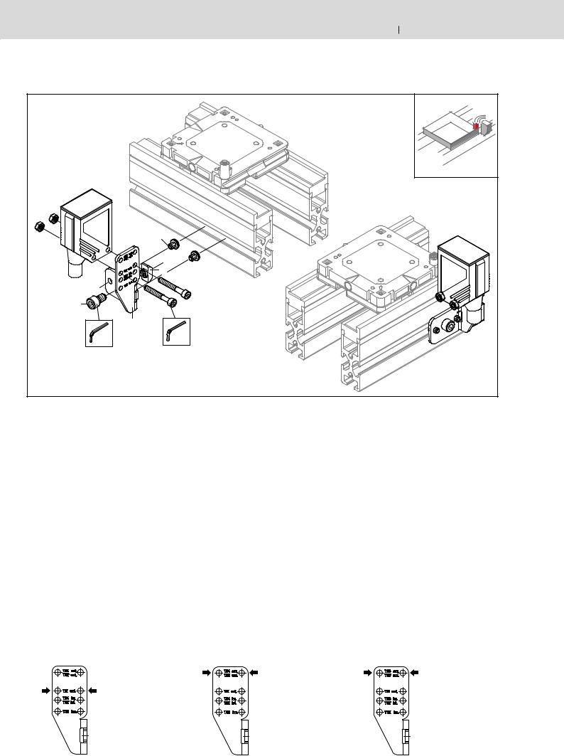
SW5 |
SW3 |
|
|
|
|
|
|
M D = 5Nm |
M D = 2,5Nm |
|
536035-01.eps |
|
|
|
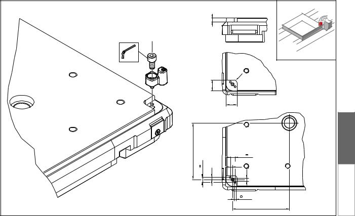
Montage ID 15/SLK, ext ern an TS 1 Assembly ID 15/SLK, ext ernally on TS 1
Montage ID 15/SLK externe sur TS 1
1) Zentrierpin für 8er Nut Centering pin for 8 mm groove
Broche de centrage rainure de 8 mm
Montage I D 15/SLK, ext ern an TS 2 Assembly ID 15/SLK, ext ernally on TS 2
Montage ID 15/SLK, externe sur TS 2
1) Zentrierpin für 10er Nut Centering pin for 10 mm groove Broche de centrage rainure de 10 mm
Montage I D 15/ SLK, ext ern an TS 4 Assembly ID 15/SLK, externally on TS 4
Montage I D 15/SLK, ext erne sur TS 4
1) Zentrierpin für 10er Nut Centering pin for 10 mm groove Broche de centrage rainure de 10 mm
2 ) Hammermutter 8er Nut, M6 |
|
|
|
|
|
|
T-nut for 8 mm groove, M6 |
2) |
Hammermutter 10er Nut, M6 |
2) |
Hammermutter 10er Nut, M6 |
|
Écrou à tête rect. rainure de 8 mm, M6 |
|
T-nut for 10 mm groove, M6 |
|
T-nut for 10 mm groove, M6 |
3 ) |
DI N 912 - M6 x 10 |
|
Écrou à tête rect. rainure de 10 mm, M6 |
|
Écrou à tête rect. rainure de 10 mm, M6 |
|
|
|
|
||
4 ) |
Anschraubposition |
3) |
DI N 912 - M6 x 16 |
3) |
DI N 912 - M6 x 16 |
|
|
|
|
||
|
Tightening position |
4) |
Anschraubposition |
4) |
Anschraubposition |
|
Position de vissage |
|
Tightening position |
|
Tightening position |
|
|
|
Position de vissage |
|
Position de vissage |
536035-01B.eps |
536035-01A.eps |
536035-01A.eps |
3 842 536 035 (2006.11) |
|
ID 15 |
Bosch Rexroth AG |
11 |
|
||||
|
|
|
|
|
Schutzabdeckung ID 15
Protective cover I D 15
Couvercle de protection I D 15
3 842 537 885 |
SW13 |
MD = 20 Nm |
536035-57.eps |
DE EN FR
IT
E S PT

12 |
Bosch Rexroth AG |
|
|
|
|
ID 15 |
3 842 536 035 (2006.11) |
Mont age ID 15/MDT, extern auf WT 1/… |
|
|
|
|
|
|
|
Asembly I D 15/MDT, ext ernally on WT 1/… |
|
|
|
|
|
|
|
Mont age ID 15/MDT, externe sur WT 1/… |
|
|
|
|
|
|
|
3 842 535 916, ID 15/MDT11 |
3 842 535 916, I D 15/MDT11 |
|
|||||
|
Pz2 |
|
|
|
|
|
|
|
M D = 2Nm |
|
|
SW4 |
|
|
|
|
|
|
M D = 3Nm |
|
|
|
|
|
|
|
|
|
|
|
|
|
|
|
|
|
|
|
2,3+0,1 |
|
2,3+0,1 |
|
|
|
|
|
|
|
+0,5 |
|
|
|
|
|
+0,5 |
|
|
|
|
|
|
3 |
|
|
3 |
|
|
|
|
|
|
6 |
3 |
6 |
3 |
|
|
|
|
|
3 |
|
|
3 |
|
|
|
|
6 |
|
|
|
6 |
|
|
536035-02.eps |
|
536035-03.eps |
|
|
|
|
|
Mont age ID 15/MDT, extern auf WT 2 |
|
|
|
|
|
|
|
Assembly I D 15/MDT, ext ernally on WT 2 |
|
|
|
|
|
|
|
Mont age ID 15/MDT, externe sur WT 2 |
|
|
|
|
|
|
|
3 842 535 919, ID 15/MDT21 |
3 842 535 919, I D 15/MDT21 |
|
|||||
|
|
|
|
|
SW4 |
|
|
|
SW4 |
|
|
M D = 5Nm |
|
|
|
|
M D = 5Nm |
|
|
|
|
|
|
d=4,8 |
|
|
d=8 |
d=12,7 |
|
|
|
|
|
|
|
|
3-0,1 (2x) |
|
|
|
|
|
|
|
3,8 |
0,2 |
|
|
|
|
6 |
M5 |
7,6 |
|
|
|
|
|
|
|
|
|
|
6 |
|
|
|
|
|
|
|
|
|
|
|
3,8 |
|
|
|
|
M5 |
|
|
7,6 |
0,2 |
|
|
|
45,5 |
|
|
|
|
45,5 |
|
536035-04.eps |
|
536035-05.eps |
|
|
|
|
|
3 842 536 035 (2006.11) |
|
ID 15 |
Bosch Rexroth AG |
13 |
|
||||
|
|
|
|
|
Mont age ID 15/MDT, extern auf WT 4
Assembly ID 15/MDT, externally on WT 4
Mont age ID 15/MDT, externeal on WT 4
|
3 842 535 919, I D 15/MDT21 |
|
|
|
|
|
1) |
|
|
|
|
6 |
|
|
|
SW4 |
|
|
|
|
M D = 5Nm |
|
|
|
|
|
1) |
5 |
|
|
|
R |
|
|
|
|
+0,5 |
|
|
|
|
|
|
|
|
|
17,5 |
|
|
|
|
|
+0,51) |
|
|
|
|
17,5 |
|
|
91 |
|
7,6 |
0,2 |
|
|
|
||
|
0,2 |
|
3,8 |
|
|
7,6 |
3,8 |
|
|
|
M5 |
|
||
|
|
|
3-0,1 |
|
|
|
|
|
91 |
|
536035-06.eps |
|
|
|
1) |
|
|
|
|
|
Ausfräsung nur notwendig bei |
|
|
|
|
Plattenstärke 19,05 mm . |
|
|
|
DE EN FR
IT
E S PT
Cut-outs only necessary for plate thickness 19.05 mm.
Fraisure seulement nécessaire pour une épaisseur de plaque de 19,05 mm.
14 |
Bosch Rexroth AG |
ID 15 |
|
3 842 536 035 (2006.11) |
|
||||
|
|
|
|
|
ID 15/SLK ID 15/MDT, int ern
ID 15/SLK ID 15/MDT, internally
ID 15/SLK ID 15/MDT, int erne
3 842 535 920, ID 15/MS1 |
|
|
1) |
|
2) |
3) |
|
4) |
|
SW5 |
|
M D = 5Nm |
SW3 |
|
M D = 2,5Nm |
536035-21.eps |
|
Mont age ID 15/SLK, intern an TS 1 |
Montage I D 15/SLK, intern an TS 2 |
Montage I D 15/ SLK, int ern an TS 4 |
|||
Assembly I D 15/SLK, internally on |
Assembly ID 15/ SLK, int ernally on |
Assembly ID 15/SLK, internally on |
|||
TS 1 |
TS 2 |
TS 4 |
|||
Mont age ID 15/SLK, interne sur TS 1 |
Montage ID 15/SLK, interne sur TS 2 |
Montage I D 15/SLK, interne sur TS 4 |
|||
1) |
Zentrierpin für 8er Nut |
1) |
Zentrierpin für 10er Nut |
1) |
Zentrierpin für 10er Nut |
|
Centering pin for 8 mm groove |
|
Centering pin for 10 mm groove |
|
Centering pin for 10 mm groove |
|
Broche de centrage rainure de 8 mm |
|
Broche de centrage rainure de |
|
Broche de centrage rainure de |
|
|
|
10 mm |
|
10 mm |
2 ) |
Hammermutter 8er Nut, M6 |
2) |
Hammermutter 10er Nut, M6 |
|
|
|
T-nut for 8 mm groove, M6 |
|
T-nut for 10 mm groove, M6 |
2) |
Hammermutter 10er Nut, M6 |
|
Écrou à tête rect. rainure de 8 mm |
|
Écrou à tête rect . rainure de 10 mm, M6 |
|
T-nut for 10 mm groove, M6 |
3 ) |
DI N 912 - M6 x 10 |
3) |
DI N 912 - M6 x 16 |
|
Écrou à tête rect. rainure de 10 mm, M6 |
|
|
||||
4 ) |
Anschraubposition |
4) |
Anschraubposition |
3) |
DI N 912 - M6 x 16 |
|
|
||||
|
Tightening position |
|
Tightening position |
4) |
Anschraubposition |
|
Position de vissage |
|
Position de vissage |
|
Tightening }position |
|
|
|
|
|
Position de vissage |
536035-01D.eps |
536035-01C.eps |
536035-01C.eps |
 Loading...